

Page 1
Instructions-Parts
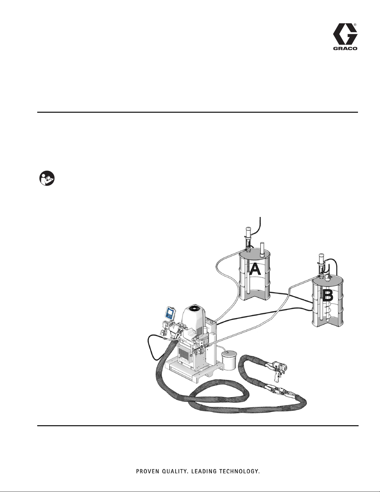
Feed Supply Kits
For supplying viscous materials to Graco® HFR™ Metering System.
For professional use only.
Important Safety Instructions
Read all warnings and instructions in this manual. Save these instructions.
See page 3 for model information, including maximum working pressure and approvals.
3A0235G
EN
246081 Package shown installed in HFR
proportioning system. Some parts shown
are not included in kit.
Page 2

Related Manuals
Contents
Related Manuals . . . . . . . . . . . . . . . . . . . . . . . . . . . 2
Complete Supply Pump Systems . . . . . . . . . . . . . 3
Warnings . . . . . . . . . . . . . . . . . . . . . . . . . . . . . . . . . 4
Isocyanate Conditions . . . . . . . . . . . . . . . . . . . . . . 6
Material Self-ignition . . . . . . . . . . . . . . . . . . . . . . . 6
Moisture Sensitivity of Isocyanates . . . . . . . . . . . . 6
Keep Components A and B Separate . . . . . . . . . . 6
Foam Resins with 245 fa Blowing Agents . . . . . . . 6
Changing Materials . . . . . . . . . . . . . . . . . . . . . . . . . 6
A and B Components . . . . . . . . . . . . . . . . . . . . . . . 7
. . . . . . . . . . . . . . . . . . . . . . . . . . . . . . . . . . . . . . 7
Grounding . . . . . . . . . . . . . . . . . . . . . . . . . . . . . . . . 8
Flush Pumps Before Using . . . . . . . . . . . . . . . . . . . 8
Position Drums . . . . . . . . . . . . . . . . . . . . . . . . . . . . 8
Installation . . . . . . . . . . . . . . . . . . . . . . . . . . . . . . . . 8
Feed Pump . . . . . . . . . . . . . . . . . . . . . . . . . . . . . 8
T2 2:1 and Monark 5:1 . . . . . . . . . . . . . . . . . . . 10
Husky 1050 Wall Mount . . . . . . . . . . . . . . . . . . 10
Husky 515 and 716 . . . . . . . . . . . . . . . . . . . . . . 11
High-Flo
Install Air Supply Kit . . . . . . . . . . . . . . . . . . . . . . . 12
T2 2:1, Husky 515, Husky 716, and Husky 1050 Kits
Air Regulator Kit 248829 . . . . . . . . . . . . . . . . . . 12
Connect Air Lines . . . . . . . . . . . . . . . . . . . . . . . . . 12
Operation . . . . . . . . . . . . . . . . . . . . . . . . . . . . . . . . 13
Startup . . . . . . . . . . . . . . . . . . . . . . . . . . . . . . . 13
Shutdown . . . . . . . . . . . . . . . . . . . . . . . . . . . . . 13
Changing Drums . . . . . . . . . . . . . . . . . . . . . . . . 13
Maintenance . . . . . . . . . . . . . . . . . . . . . . . . . . . . . . 13
Repair . . . . . . . . . . . . . . . . . . . . . . . . . . . . . . . . . . . 13
Parts . . . . . . . . . . . . . . . . . . . . . . . . . . . . . . . . . . . . 14
Complete Supply Pump Systems . . . . . . . . . . . 14
Complete Supply Pump Systems, continued . . 15
Fluid Supply Kits (1) . . . . . . . . . . . . . . . . . . . . . 16
Fluid Supply Kits (1), continued . . . . . . . . . . . . 18
Pump with Riser Tube Kits . . . . . . . . . . . . . . . . 19
Pumps with Riser Tube Kits, continued . . . . . . . 21
Accessories . . . . . . . . . . . . . . . . . . . . . . . . . . . . . . 22
Technical Data . . . . . . . . . . . . . . . . . . . . . . . . . . . . 23
Graco Standard Warranty . . . . . . . . . . . . . . . . . . . 24
Graco Information . . . . . . . . . . . . . . . . . . . . . . . . 24
®
Pumps . . . . . . . . . . . . . . . . . . . . . . . 11
12
Related Manuals
Manual Description
313997 HFR Operation
313998 HFR Repair-Parts
311882
307044
307043
308116
308981
309116
312877 Husky 1050 Pump
311211
T2 2:1 Ratio Transfer Pump
Instructions-Parts
55 Gallon 5:1 Ratio Monark
Instructions-Parts
5:1 Ratio Monark Air Motor,
Instructions-Parts
Stainless Steel Pumps,
Instructions-Parts
™
Husky
Husky 515 and Husky 716 Drum Pump
Kits and Packages, Instructions-Parts
High-Flo
515 and Husky 716 Pump
®
Pumps, Instructions-Parts
®
Pump,
2 3A0235G
Page 3
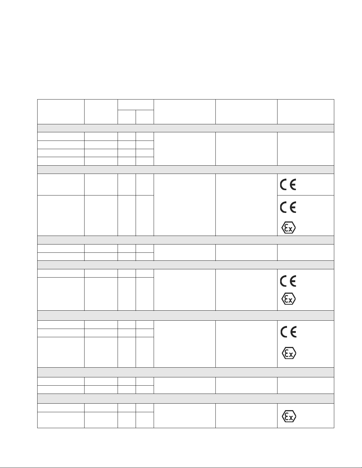
Complete Supply Pump Systems
Complete Supply Pump Systems
Most packages include all air and fluid fittings and hoses. Approvals are only for the pumps and not for the entire
package.
★ Complete Package only comes with one pump, air and fluid fittings, and hoses.
Complete
Package (fluid
and air)
Pump
Model
T2 2:1 Ratio
246081 295616
24D091 295616
24E396★ 295616
24E397★ 295616
Husky™ 515
246369 246484
24D092 241564
Husky™ 716
246375 246485
24D093 D54311
Husky™ 1050
24D328 647673
Material
✔
✔
✔
✔
✔
Maximum Air
Input Pressure
✔
180 psi
(1.2 MPa, 12.5 bar)
✔
100 psi
(0.7 MPa, 7 bar)
✔
100 psi
(0.7 MPa, 7 bar)
✔
Maximum Fluid
Working Pressure ApprovalsCS SS
405 psi
(2.8 MPa, 28 bar)
100 psi
(0.7 MPa, 7 bar)
100 psi
(0.7 MPa, 7 bar)
0359
0359
II 2 GD c IIC T4
0359
II 2 GD c IIC T4
24D094 651458
125 psi
(0.86 MPa, 8.6 bar)
✔
125 psi
(0.86 MPa, 8.6 bar)
Monark® 5:1 Ratio, 55 Gallon
24D095 218956
24E398★ 218956
24G714 224350
✔
✔
180 psi
(1.2 MPa, 12.5 bar)
✔
900 psi
0359
(6.2 MPa, 62 bar)
II 1/2 G T2
ITS03ATEX11228
Monark® 5:1 Ratio, 5 Gallon
24D096 902278
24E399★ 902278
✔
180 psi
(1.2 MPa, 12.5 bar)
✔
900 psi
(6.2 MPa, 62 bar)
High-Flo® Pumps
257769 JC20L1
257777 JS20L1
3A0235G 3
✔
100 psi
(0.7 MPa, 7 bar)
✔
200 psi
(1.4 MPa, 14 bar)
II 2 Gc T3
Page 4
Warnings
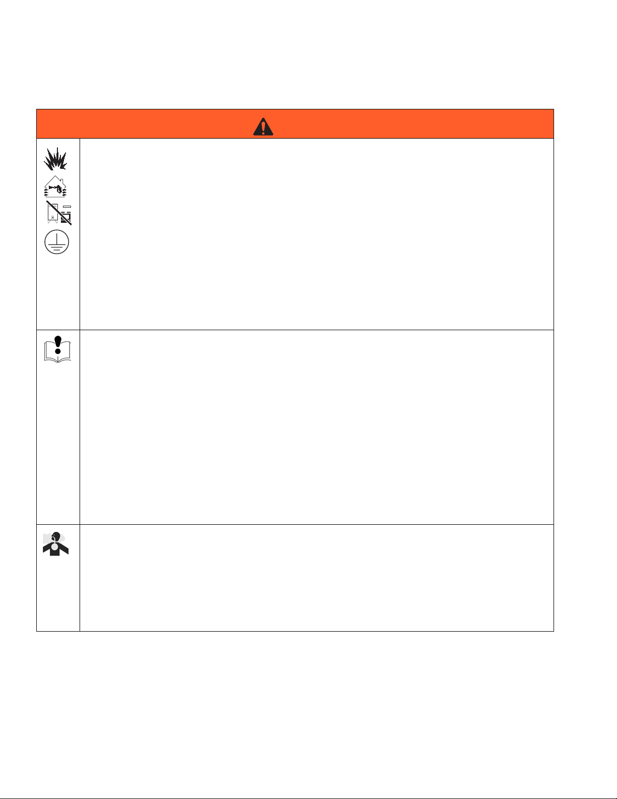
Warnings
FIRE AND EXPLOSION HAZARD
Flammable fumes, such as solvent and paint fumes, in work area can ignite or explode. To help prevent
fire and explosion:
• Use equipment only in well ventilated area.
• Eliminate all ignition sources; such as pilot lights, cigarettes, portable electric lamps, and plastic drop
cloths (potential static arc).
• Keep work area free of debris, including solvent, rags and gasoline.
• Do not plug or unplug power cords, or turn power or light switches on or off when flammable fumes
are present.
• Ground all equipment in the work area. See Grounding instructions.
• Use only grounded hoses.
• Hold gun firmly to side of grounded pail when triggering into pail.
• If there is static sparking or you feel a shock, stop operation immediately. Do not use equipment
until you identify and correct the problem.
• Keep a working fire extinguisher in the work area.
WARNING
EQUIPMENT MISUSE HAZARD
Misuse can cause death or serious injury.
• Do not operate the unit when fatigued or under the influence of drugs or alcohol.
• Do not exceed the maximum working pressure or temperature rating of the lowest rated system
component. See Technical Data in all equipment manuals.
• Do not leave the work area while equipment is energized or under pressure. Turn off all equipment
and follow the Pressure Relief Procedure when equipment is not in use.
• Check equipment daily. Repair or replace worn or damaged parts immediately with genuine manufacturer’s replacement parts only.
• Do not alter or modify equipment.
• Use equipment only for its intended purpose. Call your distributor for information.
• Route hoses and cables away from traffic areas, sharp edges, moving parts, and hot surfaces.
• Do not kink or over bend hoses or use hoses to pull equipment.
• Keep children and animals away from work area.
• Comply with all applicable safety regulations.
TOXIC FLUID OR FUMES HAZARD
Toxic fluids or fumes can cause serious injury or death if splashed in the eyes or on skin, inhaled, or
swallowed.
• Read MSDS’s to know the specific hazards of the fluids you are using.
• Store hazardous fluid in approved containers, and dispose of it according to applicable guidelines.
• Always wear impervious gloves when spraying or cleaning equipment.
• If this equipment is used with isocyanate material, see additional information on isocyanates in Isocyanate Conditions Section of this manual.
4 3A0235G
Page 5

Warnings
WARNING
MOVING PARTS HAZARD
Moving parts can pinch or amputate fingers and other body parts.
• Keep clear of moving parts.
• Do not operate equipment with protective guards or covers removed.
• Pressurized equipment can start without warning. Before checking, moving, or servicing equipment,
follow the Pressure Relief Procedure. Disconnect power or air supply.
PERSONAL PROTECTIVE EQUIPMENT
You must wear appropriate protective equipment when operating, servicing, or when in the operating
area of the equipment to help protect you from serious injury, including eye injury, hearing loss, inhalation of toxic fumes, and burns. This equipment includes but is not limited to:
• Protective eyewear, and hearing protection.
• Respirators, protective clothing, and gloves as recommended by the fluid and solvent manufacturer.
3A0235G 5
Page 6

Isocyanate Conditions
Isocyanate Conditions
Spraying materials containing isocyanates creates
potentially harmful mists, vapors, and atomized particulates.
Read material manufacturer’s warnings and material
MSDS to know specific hazards and precautions
related to isocyanates.
Prevent inhalation of isocyanate mists, vapors, and
atomized particulates by providing sufficient ventilation in the work area. If sufficient ventilation is not
available, a supplied-air respirator is required for
everyone in the work area.
To prevent contact with isocyanates, appropriate personal protective equipment, including chemically
impermeable gloves, boots, aprons, and goggles, is
also required for everyone in the work area.
Material Self-ignition
To prevent exposing ISO to moisture:
• Always use a sealed container with a desiccant
dryer in the vent, or a nitrogen atmosphere. Never
store ISO in an open container.
• Keep the ISO lube pump reservoir (if installed) filled
with Graco IsoGuard Select
The lubricant creates a barrier between the ISO and
the atmosphere.
• Use moisture-proof hoses specifically designed for
ISO, such as those supplied with your system.
• Never use reclaimed solvents, which may contain
moisture. Always keep solvent containers closed
when not in use.
• Never use solvent on one side if it has been contaminated from the other side.
• Always lubricate threaded parts with ISO pump oil
or grease when reassembling.
®
(ISG), Part 24D086.
Keep Components A and B Separate
Some materials may become self-igniting if applied
too thickly. Read material manufacturer’s warnings
and material MSDS.
Moisture Sensitivity of Isocyanates
Isocyanates (ISO) are catalysts used in two component
foam and polyurea coatings. ISO will react with moisture
(such as humidity) to form small, hard, abrasive crystals,
which become suspended in the fluid. Eventually a film
will form on the surface and the ISO will begin to gel,
increasing in viscosity. If used, this partially cured ISO
will reduce performance and the life of all wetted parts.
NOTE: The amount of film formation and rate of
crystallization varies depending on the blend of ISO,
the humidity, and the temperature.
NOTICE
To prevent cross-contamination of the equipment’s
wetted parts, never interchange component A (red)
and component B (blue) parts.
Foam Resins with 245 fa Blowing Agents
Some foam blowing agents will froth at temperatures
above 90°F (33°C) when not under pressure, especially
if agitated. To reduce frothing, minimize preheating in a
circulation system.
Changing Materials
• When changing materials, flush the equipment multiple times to ensure it is thoroughly clean.
• Always clean the fluid inlet strainers after flushing.
• Check with your material manufacturer for chemical
compatibility.
6 3A0235G
Page 7

A and B Components
A and B Components
IMPORTANT!
Material suppliers can vary in how they refer to plural
component materials.
Be aware that when standing in front of the manifold on
proportioner:
• Component A (Red) is on the left side.
• Component B (Blue) is on the right side.
For all machines:
• The A (Red) side is intended for ISO, hardeners,
and catalysts.
• If one of the materials being used is moisture-sensitive, that material should always be in the A (Red)
side.
• The B (blue) side is intended for polyols, resins, and
bases.
• For ratios higher than 1:1, the higher volume is
typically the B (Blue) side.
3A0235G 7
Page 8

Grounding
Grounding
The equipment must be grounded. Grounding reduces
the risk of static and electric shock by providing an
escape wire for the electrical current due to static build
up or in the event of a short circuit.
Pump: follow instructions in separate feed pump manual, supplied.
HFR: see operation manual.
Spray gun: see gun manual.
Fluid supply container: follow local code.
Object being sprayed: follow local code.
Solvent pails used when flushing: follow local code.
Use only conductive metal pails, placed on a grounded
surface. Do not place the pail on a nonconductive surface, such as paper or cardboard, which interrupts
grounding continuity.
To maintain grounding continuity when flushing or
relieving pressure: hold metal part of the spray gun or
dispense valve firmly to the side of a grounded metal
pail, then trigger the gun or valve.
Flush Pumps Before Using
Position Drums
Place component A (red) and component B (blue)
drums as desired. Air hose (C) connecting feed pumps
is 15 ft (4.57 m) long. See F
Fluid hose (103) connecting feed pumps to systems are
10 ft (3.05 m) long.
IG. 1.
Installation
Feed Pump
1. Complete Setup instructions in pump manual
before installing in drum or pail.
a. For Riser Tube Kit 246419: Inspect bung o-ring
(309) and gasket (303) in place. If either is worn
or damaged, or if material shows signs of crystallization, replace. See page 22.
b. If required, install desiccant dryer (Graco part
no. 247616 not included). Remove elbow and 2
in. bushing supplied with desiccant dryer (6).
Screw dryer 3/4 npt fitting into vent of moisture
sensitive drum.
NOTICE
Lubricate bung o-ring with 217374 ISO Pump Oil
each time you change drums. This keeps air and
moisture from reacting with material and allows bung
adapter to rotate freely.
NOTICE
Tighten pump clamps and external fasteners before
first use. See pump manual.
Flush equipment only in a well-ventilated area. Do not
spray flammable fluids. Do not turn on heaters while
flushing with flammable solvents.
8 3A0235G
Page 9
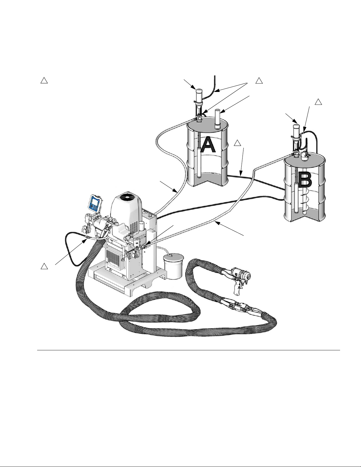
Complete Package 246081 shown installed in HFR proportioning system. Includes *parts only.
101* (red)
2
Air Supply Kit. See 309827.
2
2
6*
101* (blue)
2
C*
*103 (Ref)
Installation
2*
2
2
2*
IG. 1: Installation
F
D
103* (Ref)
3A0235G 9
Page 10

Installation
T2 2:1 and Monark 5:1
1. Flush pumps, page 8.
2. Position drums, page 8.
3. Open drum bung hole. Screw bung adapter with
gasket into bung hole. See pump manual.
4. Install swivel fitting (102) in pump fluid outlet. See
F
IG. 2.
5. Connect hose (103) between swivel fitting (102) and
the system swivel inlet (D, see F
6. Install air supply kit and connect air lines, page 12,
to finish installation.
IG. 1).
201
Husky 1050 Wall Mount
1. Be sure wall can support weight of pump, hoses,
and accessories, and can withstand stress during
operation.
2. Position wall bracket (204) no more than 5 ft (1.52
m) above floor. Check that bracket is level. Attach to
wall, using screws long enough to keep bracket from
vibrating. See F
3. Connect swivel union (209) to pump inlet.
4. Install bushing (105) in pump air inlet.
5. Install pump (201) on bracket (204) securely, using
screws (211), washers (210), and nuts (212).
6. Connect elbow (210) to top of riser tube kit (202).
7. Connect suction hose (203) to elbow (210) and inlet
swivel (209).
8. Install swivel fitting (102) in pump fluid outlet. See
F
IG. 4.
IG. 3.
bung adapter
F
IG. 2. Standard 2:1 Kit
102
TI10281a
103
9. Connect hose (103) between swivel fitting (102) and
™
GMS
swivel inlet fitting. See FIG. 4.
10. Install air supply kit and connect air lines, page 12,
to finish installation.
201
105
209
203
210
212
211
213
204
202
r_24D329_3a0235_1a
F
IG. 3. Husky 1050 Wall Mount
10 3A0235G
Page 11

Installation
Husky 515 and 716
1. Place riser tube (202) into drum. Tighten bung
adapter securely.
2. For carbon steel supply pump systems, Install
swivel fitting (102) in pump (201) fluid outlet.
3. Connect hose (103) between swivel fitting (102) and
GMS swivel fluid inlet fitting.
4. Install air supply kit and connect air lines, page 12,
to finish installation.
201
102
103
High-Flo® Pumps
1. Install elbow fitting (106) in pump (101) fluid outlet.
2. Connect hose (103) between elbow fitting (106) and
fitting (102). Install nipple (109) and swivel fitting
(110).
3. Connect swivel fitting (110) and GMS swivel fluid
inlet fitting.
For A-Side only: remove 1/2 npt swivel fitting from GMS
swivel fluid inlet prior to connecting swivel fitting (10).
4. Connect air lines (not supplied), page 12, to finish
installation.
101
202
F
IG. 4. Husky 716
r_246481_3a0235a_1a
102
110
109
F
IG. 5: High-Flo
106
103
111
r_257769_3a0235a_1a
3A0235G 11
Page 12

Install Air Supply Kit
Install Air Supply Kit
Trapped air can cause the pump to cycle unexpectedly, which could result in serious injury from splashing or moving parts.
T2 2:1, Husky 515, Husky 716, and Husky 1050 Kits
1. Supply clean, dry filtered air to feed pumps.
2. See manual 309827 to install air supply kit.
Air Regulator Kit 248829
The air regulator kit (7) is only used with the Monark kits.
1. Install air regulator kit (7).
2. Interconnect tee fitting (1f) and quick disconnect fitting (1b) on pump with air hose (1a).
Connect Air Lines
T2 2:1, Husky 515, Husky 716, and Husky 1050.
See manual 309827 to install air supply kit.
5:1 Monark Kits
1. Shut off air valves (V) at feed pumps (201).
201
V
7
1b
1a
2. Install air line (1a) with quick disconnect coupler
(1b) provided.
3. Connect air line and quick disconnect coupler to air
regulator (7).
r_256276_312769_2A
12 3A0235G
Page 13

Operation
Startup
1. See Load fluid with feed pumps in system operation manual.
2. Open feed pump air regulator.
3. Open feed pump bleed-type master air valve.
4. Adjust air to feed pump with needle valve.
NOTE:
• Cold, viscous material may be difficult to prime.
Use needle valve to reduce air flow to motor.
• Do not plug or shut off pump fluid outlet when
priming. Fluid must be free to flow through
pump to prime.
• To increase pump flow rate and reduce icing,
remove pump muffler. This will increase exhaust
noise.
Operation
Maintenance
NOTE:
See supplied pump manual for maintenance, repair, and
parts information.
Lubricate bung o-ring (309) with 217374 ISO Pump Oil
each time you change drums. This keeps air and moisture from reacting with ISO.
Whenever pump is removed from drum, inspect bung
o-ring (309) and gasket (303) in place. If either is worn
or damaged, or if ISO shows signs of crystallization,
replace. See page 22.
Tighten pump clamps and external fasteners periodically. See pump manual.
Repair
5. Never let pump run when drum is empty. A dry
pump can accelerate and damage itself. If pump is
running too fast, stop it immediately. Check and refill
fluid supply, or flush with compatible solvent. Always
prime entire system to remove any air. Do not let
material harden in pump.
Shutdown
See Shutdown and Pressure Relief Procedure in system
operation manual. Close feed pump bleed-type master
air valve.
Changing Drums
NOTICE
To prevent cross-contamination of fluid when changing drums, complete changing one component
before changing second component.
1. See Shutdown above.
2. Remove riser tube from drum. Install in new drum,
page 8.
See supplied pump manual for maintenance, troubleshooting, and repair procedures.
3. Lubricate bung o-ring, page 8.
4. See Load fluid with feed pumps in GMS operation
manual.
3A0235G 13
Page 14

Parts
Parts
Complete Supply Pump Systems
Each complete supply pump system includes a fluid supply kit, air supply kit, and desiccant dryer. See parts lists on
pages 15.
Two Pump Systems One Pump Systems
Pump Material
Complete
Pump System
Fluid Supply Kit (1)
(See Page 16)
Complete Pump
System
Husky 515 CS 246369 246481
SS 24D092 24D100
Husky 716 CS 246375 246482
SS 24D093 24D101
Husky 1050 CS 24D328 24D332
SS 24D094 24D102
T2 2:1 CS 246081 246898 24E396
SS 24D091 24D103 24E397
Monark 5:1, 5 Gallon SS 24D096 24D104 24E399
Monark 5:1, 55 Gallon CS 24D095 24D105 24E398
Monark 5:1, 55 Gallon SS
24D105 24G714
High-Flo CS 257769 257769 (page 18)
High-Flo SS 257777 257777 (page 18)
246081 Package shown installed in HFR
proportioning system. Includes * parts only.
2*
6*
2
1* (blue)
1* (red)
2*
2
1*(Ref)
1
1* (Ref)
2*
2
14 3A0235G
1
1
Fluid Supply Kit. See page 16.
2
Air Supply Kit. See 309827.
Page 15

Complete Supply Pump Systems, continued
Parts
Ref. Part Description Qty.
1★ 246481 KIT, fluid supply, Husky 515;
246369
24D100 KIT, fluid supply, Husky 515;
24D092
246482 KIT, fluid supply, Husky 716;
246375
24D101 KIT, fluid supply, Husky 716;
24D093
24D332 KIT, fluid supply, Husky 1050;
24D328
24D102 KIT, fluid supply, Husky 1050;
24D094
246898 KIT, fluid supply, T2 2:1; 246081 1
24D103 KIT, fluid supply, T2 2:1; 24D091 1
24D104 PUMP, Monark 5:1, 5 gallon;
24D095
24D105 PUMP, Monark 5:1, 55 gallon;
24D096; see manual 307044
257769 KIT, complete, High-Flo; cs 1
257777 KIT, complete, High-Flo; ss 1
2 246483 AIR SUPPLY KIT; see 309827 1
6 247616 KIT, desiccant dryer; for A (red)
side; see page 14
7❖ 248829 REGULATOR KIT, air, feed pump 1
★ See Fluid Supply Kits on page 16.
❖ Only for Monark 5:1 kits.
Husky and T2 2:1 Kits
1
See illustration on page 14.
1
24D096 and 24E399 Monark 5:1
1
5 Gallon Feed Pump Kit
1
1
1
1
1
1
1
7
r_24D095_3a0235_1a
24D095 and 24E398 Monark 5:1 Kit
55 Gallon Feed Pump Kit
1
7
r_24D096_3a0235a_1a
3A0235G 15
Page 16

Parts
Fluid Supply Kits (1)
Carbon Steel Husky Kits
101
102
Stainless Steel Husky Kits
101
24D105 55 Gallon Monark 5:1 Kit
101
103
103
r_246481_3a0235a_1a
103
246898 and 24D103 T2 2:1 Kits
r_24d101_3a0235a_1a
24D104 Monark 5:1 5 Gallon Kit
103
101
102
103
101
TI10282a
r_24D104_3a0235a_1a
16 3A0235G
Page 17

Parts
Fluid Supply Kits (1), continued
Each fluid supply kit contains two pumps with riser tubes, fittings, and hoses needed to supply fluid from the pumps
to the proportioner. Use the tables below to identify what parts are used for the carbon steel and stainless steel fluid
supply kits. See page 16 for fluid supply kit illustrations.
High-Flo pumps are on page 18.
Carbon Steel Fluid Supply Kits
Husky
Ref.
No. Description
101 KIT, pump with riser tube 246484 246485 647673 295616 2
102 UNION, swivel; UNION, swivel; 3/4 npt(m) x 3/4
npsm(f)
103 HOSE, fluid; 3/4 npt (mbe); 3/4 in. (19 mm) ID; 10 ft
(3.05 m); nylon
104 FITTING, swivel; 1/2 npt(m) x 3/4 nps(f); (not shown)
(use as necessary to adapt 1/2 npt A side “red” inlet)
105 BUSHING, reducer, 1/2 npt(m) x 3/4 npt(f); use on 1/2
npt A side (red) inlet hose (not shown)
515
(246481)
157785 157785 157785 157785 2
217382 217382 217382 217382 2
104969 104969 104969
Husky
716
(246482)
Husky
1050
(24D332)
T2 2:1
(246898) Qty.
113344 1
Stainless Steel Fluid Supply Kits
Husky
Ref.
No. Description
101 KIT, pump with riser tube 233052 233057 651458 295616 902278 224350 2
102 UNION, swivel; UNION,
swivel; 3/4 npt(m) x 3/4
npsm(f)
103 HOSE, fluid; 3/4 npt
(mbe); 3/4 in. (19 mm) ID;
10 ft (3.05 m); ss
105 BUSHING, reducer (not
shown)
106 NIPPLE, reducing; 1 in.
npt x 3/4 npt, ss; see page
19.
515
(24D100)
24C656 24C656 24C656 24C656 24C656 24C656 2
Husky
716
(24D101)
16C628 1
Husky
1050
(24D102)
16C632 1
T2 2:1
(24D103)
122268 1
Monark
5:1
(24D104)
Monark
5:1
(24D105) Qty.
1
3A0235G 17
Page 18

Parts
Fluid Supply Kits (1), continued
257769, Carbon Steel High-Flo Fluid Supply Kit
257777, Stainless Steel High-Flo Fluid Supply Kit
110
101
102
109
111
106
103
112
r_257769_3a0235a_1a
Ref.
No. Description 257769 257777 Qty.
101 PUMP, High-Flo JC20L1 JS20L1 2
102 UNION, swivel 202966 122639 2
103 HOSE, coupled;
1/2 npt; 6 ft (10.9
m); nylon
HOSE, coupled;
1/2 npt; 6 ft (10.9
m); ss
106 FITTING, union,
adapter, 90°; 1/2
npt(f) x 1/2 nps(m)
FITTING, union,
adapter, 90°
109 NIPPLE; 3/4-14
npt
NIPPLE; 3/4 in.
npt
110 FITTING, union,
swivel; 3/4 npt
FITTING, union,
swivel; 3/4 npt
111 FRAME 253692 253692 2
112 KIT, floor/stand
bracket
113 CONTROL, air,
integrated, locking
114 SCREW, cap, sch 112566 112566 4
220372 2
214959 2
102806 2
510786 2
100627 2
123111 2
118459 2
112268 2
247312 247312 2
NXT011 NXT011 2
18 3A0235G
Page 19

Pump with Riser Tube Kits
Parts
Pump Kit No. Material
Husky 515 246366 CS
233052
(see manual 309116)
Husky 716 246367 CS
233057
(see manual 309116)
Husky 1050 24D329 CS
24D097 SS
T2 2:1 295616
(see manual 311882)
Monark 5:1,
5 Gallon
Monark 5:1,
55 Gallon
24D098 SS
24D099 CS
246366 Husky 515 Pump
201
202
Plastic
SS
SS
246367 Husky 716 Pump
201
203
202
TI3450a
Ref. Part Description Qty.
201 246485 PUMP, Husky 716; see 308981 and
read NOTICE below
202 246419 RISER TUBE KIT; see page 22 1
203 158555 NIPPLE, reducing; 1 in. npt x 3/4
npt
16C628 NIPPLE, reducing; 1 in. npt x 3/4
npt, ss; only used with fluid supply
kit 24D101
1
1
1
NOTICE
246485 Husky 716 Pump is built specifically for use
with isocyanates and is tested with oil. To order
replacement parts and repair kits, refer to the Husky
716 parts list in manual 308981.
Ref. Part Description Qty.
201 246484 PUMP, Husky 515; see 308981 and
read NOTICE below
202 246419 RISER TUBE KIT; see page 22 1
NOTICE
246484 Husky 515 Pump is built specifically for use
with isocyanates and is tested with oil. To order
replacement parts and repair kits, refer to the Husky
515 parts list in manual 308981.
3A0235G 19
1
Page 20

Parts
Pumps with Riser Tube Kits, continued
24D329 CS Husky 1050 Pump 24D097 SS Husky 1050 Pump
201
105
209
203
210
212
211
213
204
202
r_24D329_3a0235_1a
Ref. Part Description Qty.
201 647673 PUMP, Husky 1050; 24D332, see
313435
202 246419 RISER TUBE KIT; 24D332, see page 221
203 214961 HOSE, suction; 3/4 npt (mbe);
3/4 in. (19 mm) ID; 6 ft (1.8 m);
neoprene
204 189233 BRACKET, wall 1
209 202965 UNION, swivel, pump inlet;
1 in. npt(m) x 3/4 npsm(f)
210 107409 ELBOW, swivel, riser tube; 90°;
1 in. npt(m) x 3/4 npsm(f); 24D332
211 100214 WASHER, lock; 5/16 4
212 100450 SCREW, cap, hex-hd; 5/16-18;
1 in. (25 mm)
213 111303 NUT, hex; 5/16-18 4
201
105
209
203
212
211
202
213
204
r_24D097_3a0235_1a
Ref. Part Description Qty.
201 651458 PUMP, Husky 1050; 24D102, see
1
manual 313435
202 183549 TUBE, section; 24D100 1
203 221171 HOSE, suction; 3/4 npt (mbe);
1
3/4 in. (19 mm) ID; 6 ft (1.8 m);
neoprene
204 189233 BRACKET, wall 1
209 16C629 FITTING, adapter, swivel; 1 npt(m) x
1
3/4 npt(f), ss
210 16C631 ELBOW, swivel 90°, 1/2 npt(m) x 1/2
1
nps(f), ss; 24D102
211 100214 WASHER, lock; 5/16 4
212 100450 SCREW, cap, hex-hd; 5/16-18;
4
1 in. (25 mm)
213 111303 NUT, hex; 5/16-18 4
214 183553 PLUG, bung; 24D102 2
210
1
1
1
1
4
20 3A0235G
Page 21

Pumps with Riser Tube Kits, continued
24D098, 5 Gallon 5:1 Monark 24D099, 55 Gallon 5:1 Monark
Parts
Ref.
No. Part No. Description Qty.
2 246483 AIR SUPPLY KIT; see 309827 1
6 247616 KIT, desiccant dryer; for A (red)
side; see page 14
7 248829 REGULATOR KIT, air, feed pump 1
201 902278 PUMP, Monark 5:1; includes
902147, see manual 308116
7
201
Ref.
No. Part No. Description Qty.
2 246483 AIR SUPPLY KIT; see 309827 1
1
6 247616 KIT, desiccant dryer; for A (red)
side; see page 14
7 248829 REGULATOR KIT, air, feed pump 1
1
201 218956 PUMP, Monark 5:1; see 307044 1
201
7
air inlet fitting
1/4 npt
1
r_24D098_3A0235A_1a
3A0235G 21
Page 22

Accessories
Accessories
Riser Tube Kit, 246419 Return Tube Accessories
Ref. Part Description Qty.
301 159101 HOUSING, valve, intake 1
302 156592 TUBE, riser 1
303 106537 GASKET, bung 1
304 15B728 ADAPTER, bung 1
305 15B727 FITTING; 1 in. npt 1
306 15B921 SPACER 1
307 100279 BALL 1
308 159100 RETAINER, ball 1
309 110831 O-RING 1
1
Lubricate with 217374 ISO Pump Oil
each time you change drums.
305
309
304
302
1
303
See manual 309852 for installation and parts.
Material Part
Carbon Steel 246477
Stainless Steel 24D106
Circulation Kits
See manual 309852 for installation and parts.
Material Part
Carbon Steel 24E379
Stainless Steel 24D107
246483 Air Supply Kit
See manual 309827 for installation and parts.
15C381 Desiccant Dryer Cartridge
233048 Husky 716 Accessory Kit
307
301
TI3445a
308
306
Includes stainless steel bung base and stainless steel
suction tube. See manual 309116.
Material Filters
Material Part
Carbon Steel 213058 (60 mesh)
Stainless Steel 244053 (60 mesh)
NOTE: See manual 307282 for installation and parts.
22 3A0235G
Page 23

Technical Data
Maximum air input pressure
T2 Feed Pump Kit. . . . . . . . . . . . . . . . . . . . . . . . . . . . . . . 180 psi (1.2 MPa, 12 bar)
Monark 5:1 Feed Pump Kit. . . . . . . . . . . . . . . . . . . . . . . . 180 psi (1.2 MPa, 12 bar)
Husky 716 . . . . . . . . . . . . . . . . . . . . . . . . . . . . . . . . . . . . 100 psi (0.7 MPa, 7 bar)
Husky 1050 . . . . . . . . . . . . . . . . . . . . . . . . . . . . . . . . . . . 125 psi (0.86 MPa, 8.6 bar)
High-Flo . . . . . . . . . . . . . . . . . . . . . . . . . . . . . . . . . . . . . . 100 psi (0.7 MPa, 7 bar)
Maximum fluid working pressure
T2 Feed Pump Kit. . . . . . . . . . . . . . . . . . . . . . . . . . . . . . . 405 psi (2.8 MPa, 28 bar)
Monark 5:1 Feed Pump Kit. . . . . . . . . . . . . . . . . . . . . . . . 900 psi (6.2 MPa, 62 bar)
Husky 716 . . . . . . . . . . . . . . . . . . . . . . . . . . . . . . . . . . . . 100 psi (0.7 MPa, 7 bar)
Husky 1050 . . . . . . . . . . . . . . . . . . . . . . . . . . . . . . . . . . . 125 psi (0.86 MPa, 8.6 bar)
High-Flo . . . . . . . . . . . . . . . . . . . . . . . . . . . . . . . . . . . . . . 200 psi (1.4 MPa, 14 bar)
Wetted parts
Pump . . . . . . . . . . . . . . . . . . . . . . . . . . . . . . . . . . . . . . . . See supplied pump manual
Riser tube . . . . . . . . . . . . . . . . . . . . . . . . . . . . . . . . . . . . . Carbon steel
Fluid hoses . . . . . . . . . . . . . . . . . . . . . . . . . . . . . . . . . . . . Nylon
Suction hose (Husky 1050 only). . . . . . . . . . . . . . . . . . . . Neoprene
Fittings . . . . . . . . . . . . . . . . . . . . . . . . . . . . . . . . . . . . . . . Carbon steel
Technical Data
3A0235G 23
Page 24

Graco Standard Warranty
Graco warrants all equipment referenced in this document which is manufactured by Graco and bearing its name to be free from defects in
material and workmanship on the date of sale to the original purchaser for use. With the exception of any special, extended, or limited warranty
published by Graco, Graco will, for a period of twelve months from the date of sale, repair or replace any part of the equipment determined by
Graco to be defective. This warranty applies only when the equipment is installed, operated and maintained in accordance with Graco’s written
recommendations.
This warranty does not cover, and Graco shall not be liable for general wear and tear, or any malfunction, damage or wear caused by faulty
installation, misapplication, abrasion, corrosion, inadequate or improper maintenance, negligence, accident, tampering, or substitution of
non-Graco component parts. Nor shall Graco be liable for malfunction, damage or wear caused by the incompatibility of Graco equipment with
structures, accessories, equipment or materials not supplied by Graco, or the improper design, manufacture, installation, operation or
maintenance of structures, accessories, equipment or materials not supplied by Graco.
This warranty is conditioned upon the prepaid return of the equipment claimed to be defective to an authorized Graco distributor for verification of
the claimed defect. If the claimed defect is verified, Graco will repair or replace free of charge any defective parts. The equipment will be returned
to the original purchaser transportation prepaid. If inspection of the equipment does not disclose any defect in material or workmanship, repairs will
be made at a reasonable charge, which charges may include the costs of parts, labor, and transportation.
THIS WARRANTY IS EXCLUSIVE, AND IS IN LIEU OF ANY OTHER WARRANTIES, EXPRESS OR IMPLIED, INCLUDING BUT NOT LIMITED
TO WARRANTY OF MERCHANTABILITY OR WARRANTY OF FITNESS FOR A PARTICULAR PURPOSE.
Graco’s sole obligation and buyer’s sole remedy for any breach of warranty shall be as set forth above. The buyer agrees that no other remedy
(including, but not limited to, incidental or consequential damages for lost profits, lost sales, injury to person or property, or any other incidental or
consequential loss) shall be available. Any action for breach of warranty must be brought within two (2) years of the date of sale.
GRACO MAKES NO WARRANTY, AND DISCLAIMS ALL IMPLIED WARRANTIES OF MERCHANTABILITY AND FITNESS FOR A
PARTICULAR PURPOSE, IN CONNECTION WITH ACCESSORIES, EQUIPMENT, MATERIALS OR COMPONENTS SOLD BUT NOT
MANUFACTURED BY GRACO. These items sold, but not manufactured by Graco (such as electric motors, switches, hose, etc.), are subject to
the warranty, if any, of their manufacturer. Graco will provide purchaser with reasonable assistance in making any claim for breach of these
warranties.
In no event will Graco be liable for indirect, incidental, special or consequential damages resulting from Graco supplying equipment hereunder, or
the furnishing, performance, or use of any products or other goods sold hereto, whether due to a breach of contract, breach of warranty, the
negligence of Graco, or otherwise.
FOR GRACO CANADA CUSTOMERS
The Parties acknowledge that they have required that the present document, as well as all documents, notices and legal proceedings entered into,
given or instituted pursuant hereto or relating directly or indirectly hereto, be drawn up in English. Les parties reconnaissent avoir convenu que la
rédaction du présente document sera en Anglais, ainsi que tous documents, avis et procédures judiciaires exécutés, donnés ou intentés, à la suite
de ou en rapport, directement ou indirectement, avec les procédures concernées.
Graco Information
For the latest information about Graco products, visit www.graco.com.
TO PLACE AN ORDER, contact your Graco distributor or call to identify the nearest distributor.
Toll Free: 1-800-746-1334 or Fax: 330-966-3006
All written and visual data contained in this document reflects the latest product information available at the time of publication.
GRACO INC. AND SUBSIDIARIES • P.O. BOX 1441 • MINNEAPOLIS MN 55440-1441 • USA
Copyright 2010, Graco Inc. All Graco manufacturing locations are registered to ISO 9001.
Graco reserves the right to make changes at any time without notice.
For patent information, see www.graco.com/patents.
Original instructions. This manual contains English. MM 3A0235
Graco Headquarters: Minneapolis
International Offices: Belgium, China, Japan, Korea
www.graco.com
Revised February 2012
 Loading...