

Page 1
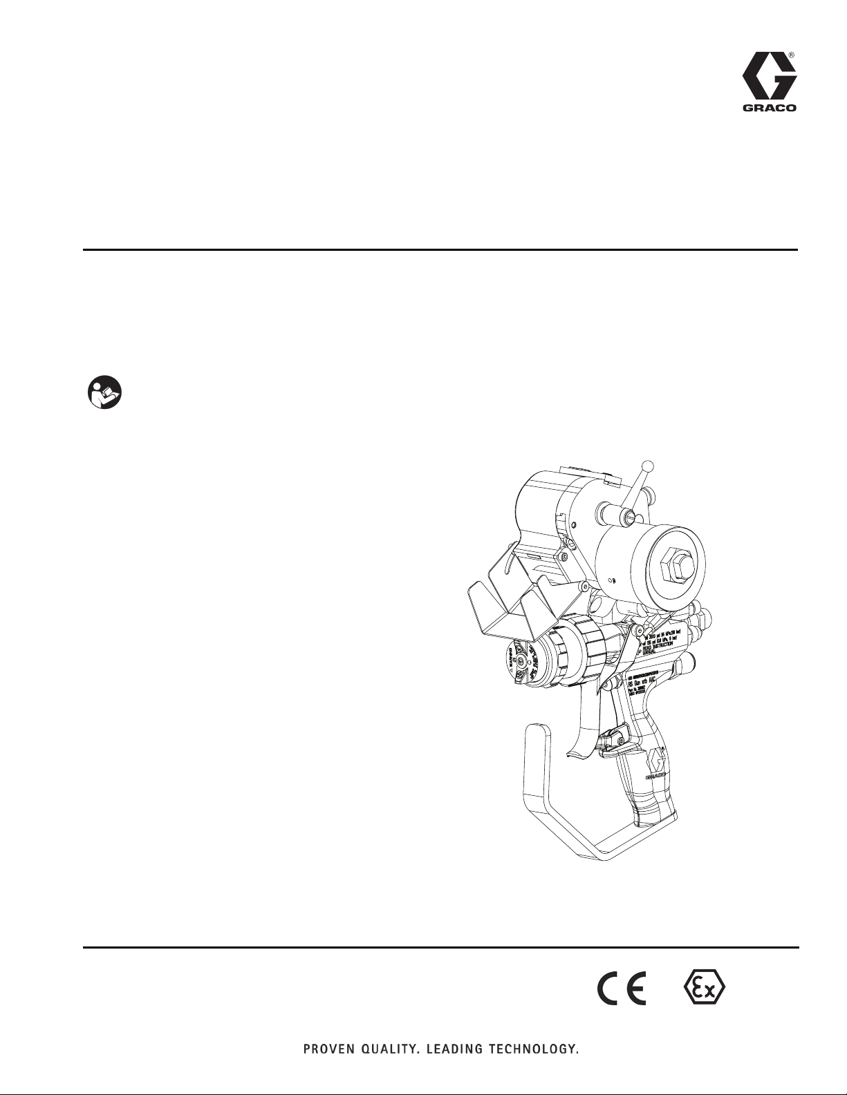
Operation - Repair
™
RS
Gun and
Cutter
For use with polyester resin and gel-coat.
For professional use only.
Important Safety Instructions
Read all warnings and instructions in this
manual. Save these instructions.
See page 3 for model information, including maximum working pressure.
3A0232R
EN
External Mix Chop Gun with Cutter shown
II 2 G c T6
Page 2

Contents
Models . . . . . . . . . . . . . . . . . . . . . . . . . . . . . . . . . . . 3
Related Manuals . . . . . . . . . . . . . . . . . . . . . . . . . . . 3
Warnings . . . . . . . . . . . . . . . . . . . . . . . . . . . . . . . . . 4
Important Two-Component Information . . . . . . . . 6
Material Self-ignition . . . . . . . . . . . . . . . . . . . . . 6
Keep Components A and B Separate . . . . . . . . . 6
Changing Materials . . . . . . . . . . . . . . . . . . . . . . . 6
Important Methyl Ethyl Ketone Peroxide (MEKP)
Safety Information . . . . . . . . . . . . . . . . . . . . . . . 7
Component Identification . . . . . . . . . . . . . . . . . . . 10
External Mix Gel Gun, 258840 . . . . . . . . . . . . . 10
Internal Mix Gel Gun, 258853 . . . . . . . . . . . . . . 11
Internal Mix Chop Gun, 258854 . . . . . . . . . . . . 12
Internal Mix Chop Gun, 24P436, High Flow, Carbide
Seat . . . . . . . . . . . . . . . . . . . . . . . . . . . . . . 13
External Mix Chop Gun, 258852 . . . . . . . . . . . 14
Theory of Operation . . . . . . . . . . . . . . . . . . . . . . . 15
External Mix . . . . . . . . . . . . . . . . . . . . . . . . . . . 15
Internal Mix . . . . . . . . . . . . . . . . . . . . . . . . . . . . 15
Chop Guns . . . . . . . . . . . . . . . . . . . . . . . . . . . . 15
Impingement versus Airless Spray Tips . . . . . . 15
Air Assist Containment
Grounding . . . . . . . . . . . . . . . . . . . . . . . . . . . . . . . 15
Introduction . . . . . . . . . . . . . . . . . . . . . . . . . . . . . . 15
Setup . . . . . . . . . . . . . . . . . . . . . . . . . . . . . . . . . . . . 16
Startup . . . . . . . . . . . . . . . . . . . . . . . . . . . . . . . . . . 18
Operation . . . . . . . . . . . . . . . . . . . . . . . . . . . . . . . . 19
Trigger Lock . . . . . . . . . . . . . . . . . . . . . . . . . . . . 19
Adjust AAC . . . . . . . . . . . . . . . . . . . . . . . . . . . . 19
Internal Mix Flush . . . . . . . . . . . . . . . . . . . . . . . 19
Pressure Relief Procedure . . . . . . . . . . . . . . . . . . 20
Shutdown . . . . . . . . . . . . . . . . . . . . . . . . . . . . . . . . 21
Daily Shutdown . . . . . . . . . . . . . . . . . . . . . . . . 21
Long-Term Shutdown . . . . . . . . . . . . . . . . . . . . 23
Maintenance . . . . . . . . . . . . . . . . . . . . . . . . . . . . . . 24
Flush System . . . . . . . . . . . . . . . . . . . . . . . . . . 24
Troubleshooting . . . . . . . . . . . . . . . . . . . . . . . . . . . 25
Fluid Leaking from Front of Gun . . . . . . . . . . . . 29
Adjust Trigger Clamp . . . . . . . . . . . . . . . . . . . . 29
Fluid Leaking from Under Trigger Clamp Assembly
30
Adjust Needle Packing Tension . . . . . . . . . . . . 30
Adjust Actuator Pin Adjustment Screws . . . . . . 31
™
(AAC™) . . . . . . . . . . . 15
Repair . . . . . . . . . . . . . . . . . . . . . . . . . . . . . . . . . . . 32
Remove Hardened Material from Internal Mix Front
Head . . . . . . . . . . . . . . . . . . . . . . . . . . . . . . 32
Replace Internal Mix Element . . . . . . . . . . . . . 34
Replace External Mix Check Valve and O-Rings 35
Replace Material Needle Assembly . . . . . . . . . . 36
Replace Center Needle Assembly . . . . . . . . . . 36
Replace Needle Packing . . . . . . . . . . . . . . . . . . 37
Parts . . . . . . . . . . . . . . . . . . . . . . . . . . . . . . . . . . . . 38
External Mix Gel Gun, 258840 . . . . . . . . . . . . . 38
Internal Mix Gel Gun, 258853 . . . . . . . . . . . . . . 40
External Mix Chop Gun with Cutter, 258970 . . . 42
Internal Mix Chop Gun with Cutter, 258971 . . . 42
Internal Mix, High Flow, Chop Gun with Cutter,
24P435 . . . . . . . . . . . . . . . . . . . . . . . . . . . . 42
Chop Guns . . . . . . . . . . . . . . . . . . . . . . . . . . . . 43
Front Head Assemblies . . . . . . . . . . . . . . . . . . . 49
Needle Assembly, 24E417 . . . . . . . . . . . . . . . . 52
O-ring Identification . . . . . . . . . . . . . . . . . . . . . . 53
Accessories . . . . . . . . . . . . . . . . . . . . . . . . . . . . . . 54
®
Fusion
INDy or Formula Adapter Kit, 125797 . . . . . . . . 54
LPA2 Adapter Kit, 125843 . . . . . . . . . . . . . . . . . 54
Universal Adapter Kit, 257754 . . . . . . . . . . . . . . 54
Resin Transfer Molding (RTM) Nozzle Adapter Kit,
Casting Nozzle Adapter Kit, 16T707 . . . . . . . . . 54
External Mix High-Flow Kit, 24H336 . . . . . . . . . 54
Internal Mix High-Flow Kit, 24H337 . . . . . . . . . . 54
AAC Regulators . . . . . . . . . . . . . . . . . . . . . . . . . 55
External Mix Gel Gun to Chop Gun Conversion 55
Internal Mix Gel Gun to Chop Gun Conversion . 55
Pressure Fed Roller Adapter Kit, 16T708 . . . . . 56
Extension Gelcoat Spraying Kit, 16T709 . . . . . . 56
Tools . . . . . . . . . . . . . . . . . . . . . . . . . . . . . . . . . 56
Carbide Resin Seat, 24M833 . . . . . . . . . . . . . . 56
External Mix Chopper Extension Kit, 24V096 . . 56
Impingement (Chop) Spray Tips . . . . . . . . . . . . 58
Airless (Gel) Spray Tips . . . . . . . . . . . . . . . . . . . 60
Technical Data . . . . . . . . . . . . . . . . . . . . . . . . . . . . 62
Dimensions . . . . . . . . . . . . . . . . . . . . . . . . . . . . 64
Graco Standard Warranty . . . . . . . . . . . . . . . . . . . 66
Graco Information . . . . . . . . . . . . . . . . . . . . . . . . . 66
Grease . . . . . . . . . . . . . . . . . . . . . . . . . 54
16T680 . . . . . . . . . . . . . . . . . . . . . . . . . . . . 54
2 3A0232R
Page 3

Models
See Technical Data on page 62 for more specifications.
Models
Model Description
258853
258854
258971
24P435
258840
258852
258970
Internal Mix
Gel Gun
Internal Mix
Chop Gun,
No Cutter
Internal Mix
Chop Gun,
Cutter
Internal Mix
Chop Gun,
High Flow,
Cutter
External Mix
Gel Gun
External Mix
Chop Gun,
No Cutter
External Mix
Chop Gun,
Cutter
Maximum Fluid
Working Pressure
psi (MPa, bar)
2000 (14, 138) 2000 (14, 138)
2000 (14, 138) 2000 (14, 138)
2000 (14, 138) 2000 (14, 138)
2000 (14, 138) 2000 (14, 138)
2000 (14, 138) 200 (1.4, 14)
2000 (14, 138) 200 (1.4, 14)
2000 (14, 138) 200 (1.4, 14)
Maximum Catalyst
Working Pressure
psi (MPa, bar)
Air Inlet Working
Pressure Range
psi (MPa, bar)
0-125
(0-0.86, 0-8.6)
0-125
(0-0.86, 0-8.6)
80-125
(0.55-0.86, 5.5-8.6)
80-125
(0.55-0.86, 5.5-8.6)
0-125
(0-0.86, 0-8.6)
0-125
(0-0.86, 0-8.6)
80-125
(0.55-0.86, 5.5-8.6)
Maximum Fluid
Tem peratu re
°F (°C)
100 (38)
100 (38)
100 (38)
100 (38)
100 (38)
100 (38)
100 (38)
Related Manuals
The following is a list of component manuals written in
English. These manuals and any translated versions
available can be found at www.graco.com.
Part Description
3A1226 Universal Adapter Kit 257754 Instructions
3A2054 Indy or Formula Adapter Kit 125797 Instructions
3A2079 LPA2 Adapter Kit 125843 Instructions
332574 RS Gun Cutter Assemblies Operation-Repair
334010 RS Gun External Mix Chopper Extension Kit 24V096 Instructions
3A0232R 3
Page 4
Warnings
Warnings
The following warnings are for the setup, use, grounding, maintenance, and repair of this equipment. The exclamation point symbol alerts you to a general warning and the hazard symbols refer to procedure-specific risks. When
these symbols appear in the body of this manual, refer back to these Warnings. Product-specific hazard symbols and
warnings not covered in this section may appear throughout the body of this manual where applicable.
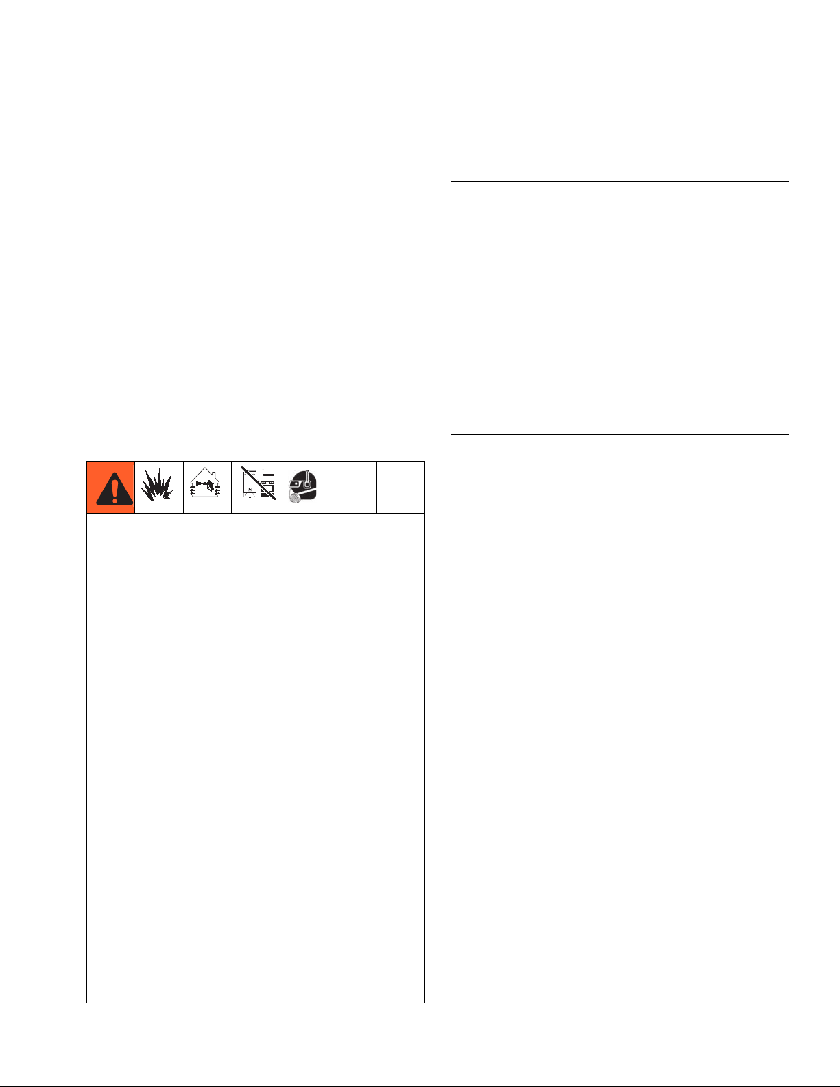
WARNING
FIRE AND EXPLOSION HAZARD
Flammable fumes, such as solvent and paint fumes, in work area can ignite or explode. To help
prevent fire and explosion:
• Use equipment only in well ventilated area.
• Eliminate all ignition sources; such as pilot lights, cigarettes, portable electric lamps, and plastic
drop cloths (potential static arc).
• Keep work area free of debris, including solvent, rags and gasoline.
• Do not plug or unplug power cords, or turn power or light switches on or off when flammable fumes
are present.
• Ground all equipment in the work area. See Grounding instructions.
• Use only grounded hoses.
• Hold gun firmly to side of grounded pail when triggering into pail.
• If there is static sparking or you feel a shock, stop operation immediately. Do not use equipment
until you identify and correct the problem.
• Keep a working fire extinguisher in the work area.
SKIN INJECTION HAZARD
High-pressure fluid from dispensing device, hose leaks, or ruptured components will pierce skin. This
may look like just a cut, but it is a serious injury that can result in amputation. Get immediate surgical
treatment.
• Engage trigger lock when not dispensing.
• Do not point dispensing device at anyone or at any part of the body.
• Do not put your hand over the fluid outlet.
• Do not stop or deflect leaks with your hand, body, glove, or rag.
• Follow the Pressure Relief Procedure when you stop dispensing and before cleaning, checking, or
servicing equipment.
• Tighten all fluid connections before operating the equipment.
• Check hoses and couplings daily. Replace worn or damaged parts immediately.
MOVING PARTS HAZARD
Moving parts can pinch, cut or amputate fingers and other body parts.
• Keep clear of moving parts.
• Do not operate equipment with protective guards or covers removed.
• Pressurized equipment can start without warning. Before checking, moving, or servicing equipment,
follow the Pressure Relief Procedure and disconnect all power sources.
4 3A0232R
Page 5
Warnings
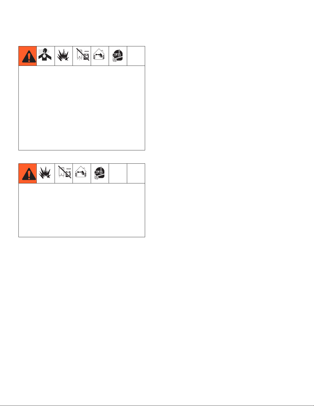
WARNING
TOXIC FLUID OR FUMES HAZARD
Toxic fluids or fumes can cause serious injury or death if splashed in the eyes or on skin, inhaled, or
swallowed.
• Read MSDSs to know the specific hazards of the fluids you are using.
• Store hazardous fluid in approved containers, and dispose of it according to applicable guidelines.
• Always wear chemically impermeable gloves when spraying, dispensing, or cleaning equipment.
PERSONAL PROTECTIVE EQUIPMENT
You must wear appropriate protective equipment when operating, servicing, or when in the operating
area of the equipment to help protect you from serious injury, including eye injury, hearing loss,
inhalation of toxic fumes, and burns. This equipment includes but is not limited to:
• Protective eyewear, and hearing protection.
• Respirators, protective clothing, and gloves as recommended by the fluid and solvent manufacturer.
EQUIPMENT MISUSE HAZARD
Misuse can cause death or serious injury.
• Do not operate the unit when fatigued or under the influence of drugs or alcohol.
• Do not exceed the maximum working pressure or temperature rating of the lowest rated system
component. See Technical Data in all equipment manuals.
• Use fluids and solvents that are compatible with equipment wetted parts. See Technical Data in all
equipment manuals. Read fluid and solvent manufacturer’s warnings. For complete information
about your material, request MSDS from distributor or retailer.
• Do not leave the work area while equipment is energized or under pressure. Turn off all equipment
and follow the Pressure Relief Procedure when equipment is not in use.
• Check equipment daily. Repair or replace worn or damaged parts immediately with genuine
manufacturer’s replacement parts only.
• Do not alter or modify equipment.
• Use equipment only for its intended purpose. Call your distributor for information.
• Route hoses and cables away from traffic areas, sharp edges, moving parts, and hot surfaces.
• Do not kink or over bend hoses or use hoses to pull equipment.
• Keep children and animals away from work area.
• Comply with all applicable safety regulations.
PRESSURIZED ALUMINUM PARTS HAZARD
Use of fluids that are incompatible with aluminum in pressurized equipment can cause serious
chemical reaction and equipment rupture. Failure to follow this warning can result in death, serious
injury, or property damage.
• Do not use 1,1,1-trichloroethane, methylene chloride, other halogenated hydrocarbon solvents or
fluids containing such solvents.
• Many other fluids may contain chemicals that can react with aluminum. Contact your material
supplier for compatibility.
3A0232R 5
Page 6
Important Two-Component Information
Important Two-Component Information
Material Self-ignition
Some materials may become self-igniting if applied
too thickly. Read material manufacturer’s warnings
and material MSDS.
Keep Components A and B Separate
Cross-contamination can result in cured material in
fluid lines which could cause serious injury or
damage equipment. To prevent cross-contamination
of the equipment’s wetted parts, never interchange
component A (catalyst) and component B (resin)
parts.
Changing Materials
• When changing materials, flush the equipment multiple times to ensure it is thoroughly clean.
• Always clean the fluid inlet strainers after flushing.
• Check with your material manufacturer for chemical
compatibility.
6 3A0232R
Page 7
Important Methyl Ethyl Ketone Peroxide (MEKP) Safety Information
Important Methyl Ethyl Ketone Peroxide (MEKP)
Safety Information
MEKP is among the more hazardous materials found in
commercial channels. Proper handling of the “unstable
(reactive)” chemicals presents a definite challenge to
the plastics industry. The highly reactive property which
makes MEKP valuable to the plastics industry in producing the curing reaction of polyester resins and gel-coats
also produces the hazards which require great care and
caution in its storage, transportation, handling, processing and disposal.
Workers must be thoroughly informed of the hazards
that may result from improper handling of MEKP, especially in regards to contamination and heat. They must
be thoroughly instructed regarding the proper action to
be taken in the storage, use and disposal of MEKP and
other hazardous materials used in the laminating operation.
MEKP is flammable and potentially explosive, as
well as potentially damaging to the eyes and skin.
Read material manufacturer’s warnings and
material MSDS to know specific hazards and precautions related to MEKP.
Contaminated MEKP can become explosive. Prevent contamination of MEKP with other materials,
which includes, but is not limited to polyester overspray, polymerization accelerators and promoters,
and non-stainless metals. Even small amounts of
contaminates can make MEKP explosive. This reaction may start slowly, and gradually build-up heat,
which can accelerate until fire or an explosion result.
This process can take from seconds to days.
Heat applied to MEKP, or heat build-up from contamination reactions can cause it to reach what is
called its Self-Accelerating Decomposition Temperature (SADT), which can cause fire or explosion. Spills
should be promptly removed, so no residues remain.
Spillage can heat up to the point of self-ignition. Dispose in accordance with manufacture’s recommendation.
Store MEKP in a cool, dry and well-ventilated area
in the original containers away from direct sunlight
and away from other chemicals. It is strongly recommended that the storage temperature remain below
86° F (30° C). Heat will increase the potential for
explosive decomposition. Refer to NFPA 432. Keep
MEKP away from heat, sparks and open flames.
Current catalysts are premixed and do not require
any diluents. Graco strongly recommends that diluents not be used. Diluents add to the possibility of
contaminates entering the catalyst system. Never
dilute MEKP with acetone or any solvent since this
can produce an extremely shock-sensitive compound
which can explode.
Use only original equipment or equivalent parts
from Graco in the catalyst system (i.e.: hoses, fittings,
etc.) because a hazardous chemical reaction may
result between substituted parts and MEKP.
To prevent contact with MEKP, appropriate personal protective equipment, including chemically
impermeable gloves, boots, aprons and goggles are
required for everyone in the work area.
3A0232R 7
Page 8
Important Methyl Ethyl Ketone Peroxide (MEKP) Safety Information
Polyester Resins and Gel-Coats
Spraying materials containing polyester resin and
gel-coats creates potentially harmful mist, vapors and
atomized particulates. Prevent inhalation by providing
sufficient ventilation and the use of respirators in the
work area.
Read the material manufacturer’s warnings and
material MSDS to know specific hazards and precautions related to polyester resins and gel-coats.
To prevent contact with polyester resins and
gel-coats, appropriate personal protective equipment,
including chemically impermeable gloves, boots,
aprons and goggles are required for everyone in the
work area.
Spraying and Lamination Operations
Remove all accumulations of overspray, FRP
sandings, etc. from the building as they occur. If this
waste is allowed to build up, spillage of catalyst is
more likely to start a fire.
If cleaning solvents are required, read material
manufacture’s warnings and material MSDS to know
specific hazards and precautions. (Graco recommends that clean-up solvents be nonflammable.)
NOTE: Graco recommends that you consult OSHA Sections 1910.94, 1910.106, 1910.107 and NFPA No. 33,
Chapter 16,17, and NFPA No. 91 for further guidance.
8 3A0232R
Page 9

Important Methyl Ethyl Ketone Peroxide (MEKP) Safety Information
3A0232R 9
Page 10
Component Identification
Component Identification
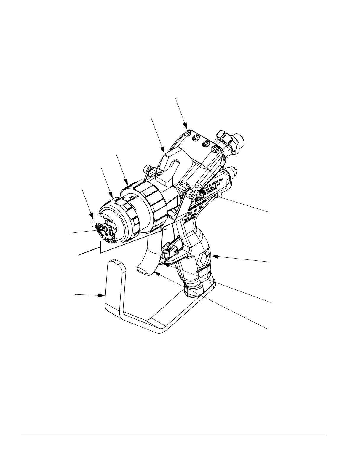
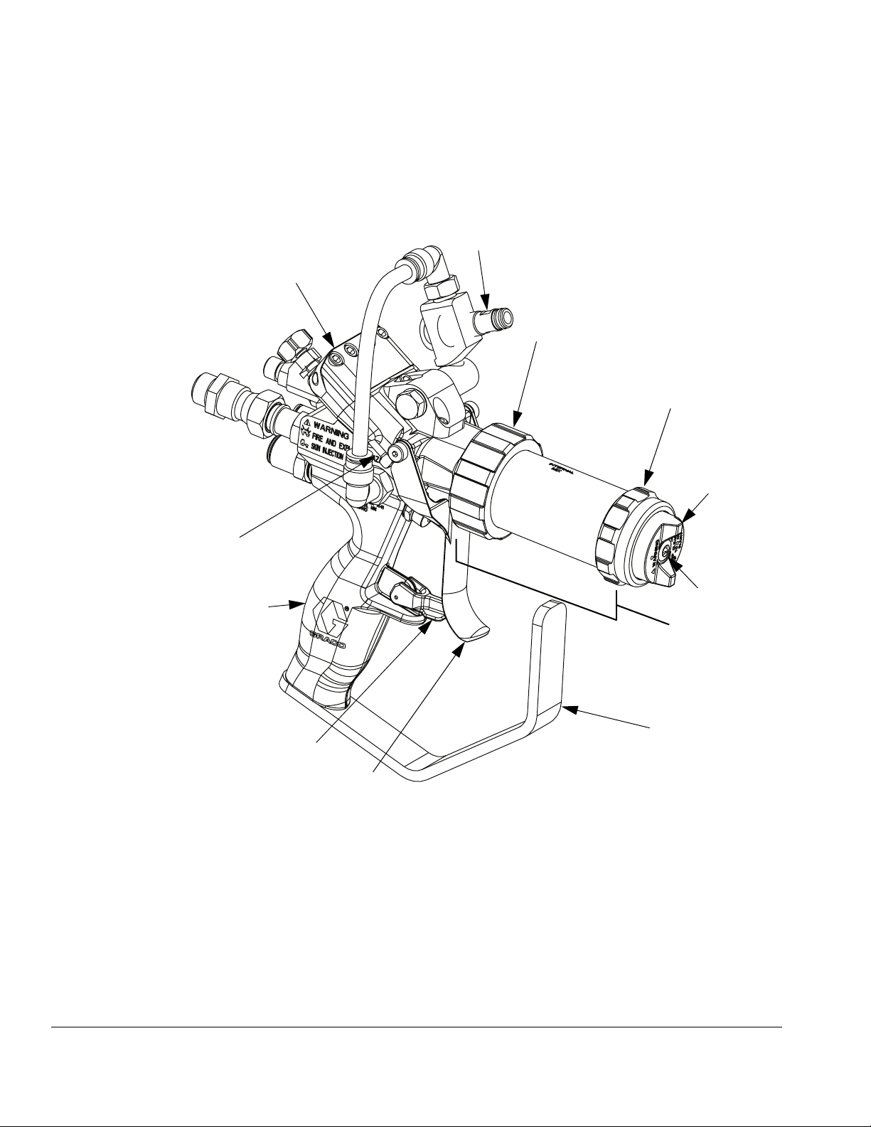
External Mix Gel Gun, 258840
B
C
D
E
A
G
F
H
Key:
A Trigger Clamp Assembly
B Gun Mount
C Front Head Locking Ring
D Air Cap Retaining Ring
E External Mix Aircap
F External Mix Front Head
258840_3A0232_1g
GSpray Tip
H Trigger guard
J Trigger
K Trigger lock
L Handle
M Actuator Pin
M
L
K
J
FIG. 1
10 3A0232R
Page 11
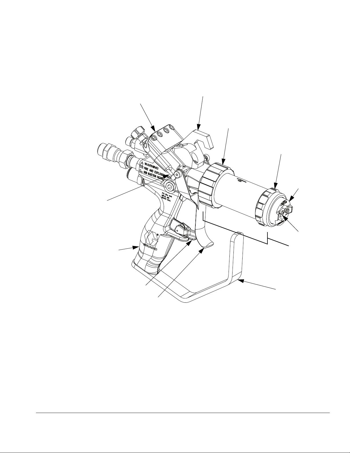
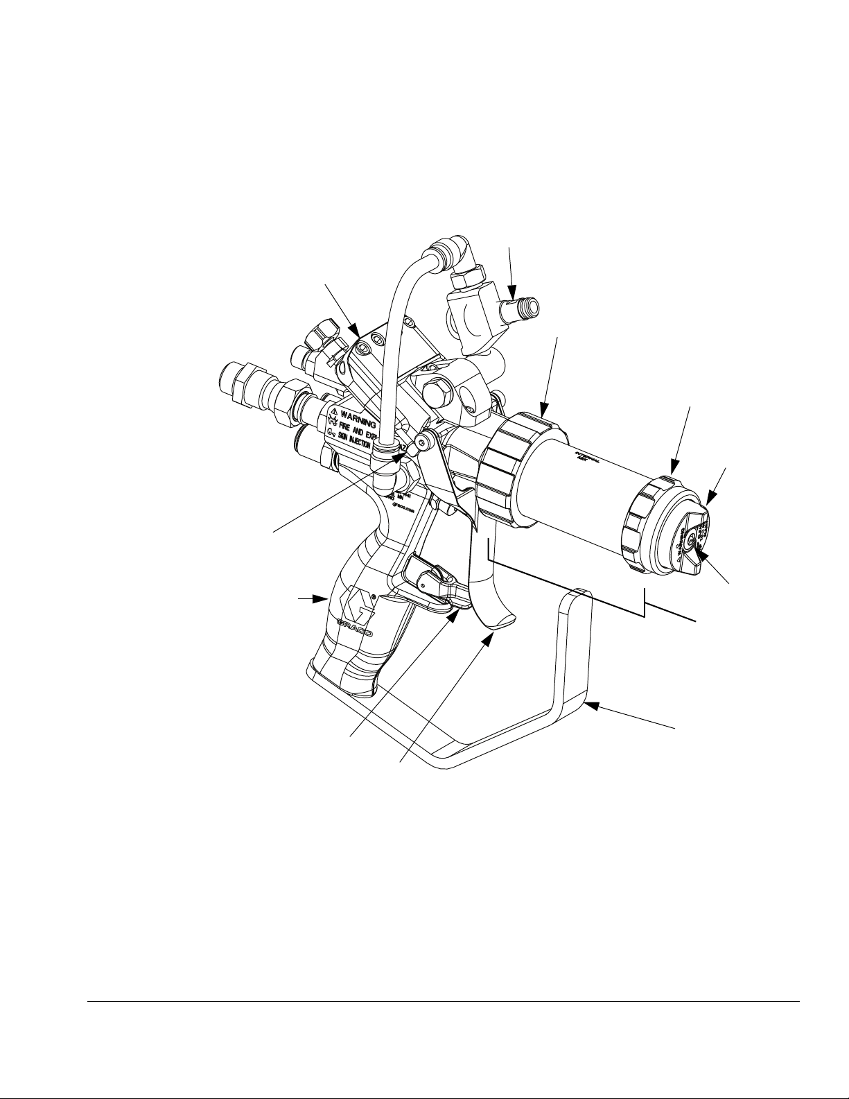
Internal Mix Gel Gun, 258853
NOTE: On internal mix guns, the tip rotates to allow a
vertical or horizontal spray pattern.
A
Component Identification
B
C
D
E
M
L
K
J
Key:
A Trigger Clamp Assembly
BGun Mount
C Front Head Locking Ring
D Air Cap Retaining Ring
E Internal Mix Aircap
F Internal Mix Front Head
G
F
H
ti21003a
GSpray Tip
H Trigger guard
J Trigger
K Trigger lock
L Handle
M Actuator Pin
IG. 2
F
3A0232R 11
Page 12
Component Identification
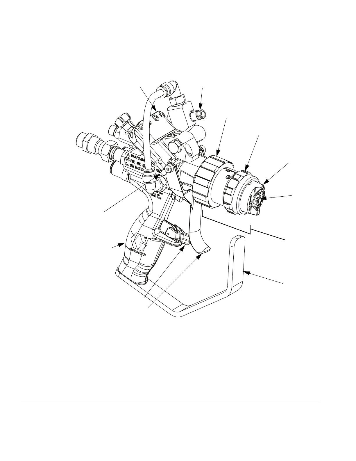
Internal Mix Chop Gun, 258854
NOTE: On internal mix guns, the tip rotates to allow ver-
tical or horizontal spray pattern.
A
B
C
D
M
L
K
Key:
A Trigger Clamp Assembly
B Cutter Mount
C Front Head Locking Ring
D Air Cap Retaining Ring
E Internal Mix Aircap
F Internal Mix Front Head
E
G
F
H
J
ti21004b
GSpray Tip
H Trigger guard
J Trigger
K Trigger lock
L Handle
MActuator Pin
IG. 3
F
12 3A0232R
Page 13
Component Identification
Internal Mix Chop Gun, 24P436, High Flow, Carbide Seat
NOTE: On internal mix guns, the tip rotates to allow ver-
tical or horizontal spray pattern.
B
A
C
D
M
L
K
Key:
A Trigger Clamp Assembly
B Cutter Mount
C Front Head Locking Ring
D Air Cap Retaining Ring
E Internal Mix Aircap
F Internal Mix Front Head,
High Flow
E
G
F
H
J
ti21005b
GSpray Tip
H Trigger guard
J Trigger
K Trigger lock
L Handle
MActuator Pin
IG. 4
F
3A0232R 13
Page 14
Component Identification
External Mix Chop Gun, 258852
M
A
B
C
D
E
G
F
L
H
K
J
ti21006b
Key:
A Trigger Clamp Assembly
B Cutter Mount
C Front Head Locking Ring
D Air Cap Retaining Ring
E External Mix Aircap
F External Mix Front Head
GSpray Tip
H Trigger guard
J Trigger
K Trigger lock
L Handle
M Actuator Pin
FIG. 5
14 3A0232R
Page 15

Theory of Operation
Theory of Operation
External Mix
The resin or gelcoat stream and the catalyst stream
impinge when they exit the spray tip. The catalyst is
atomized with air pressure by the AAC air to achieve
high mix quality. External mixing reduces internal clogs
from cured material.
Internal Mix
The material and catalyst pass through an internal static
mixer where they mix. The mixed solution is dispensed.
Chop Guns
Fiberglass is pulled through cutter and cut into small
strands. The cut strands are then dispensed into the
mixed material stream.
Grounding
This equipment must be grounded.
Grounding reduces the risk of static shock by providing
an escape wire for electrical current due to static build
up or in the event of short circuit.
NOTE: Grounding wire and clamp assembly 17440-00
is included with Graco FRP proportioner. If using a different proportioner that does not come with a grounding wire and clamp assembly, order 17440-00 or
provide your own.
Ground the dispense gun through connection to a
Graco approved grounded fluid supply hose.
Check your local electrical code and related manuals
for detailed grounding instructions of all equipment in
the work area.
Impingement versus Airless Spray Tips
Impingement spray tips are typically for chop guns. This
utilizes multiple impinging streams to create the fan pattern.
Airless spray tips are typically for gel guns. This utilizes
a single cat-eye shaped orifice to create the fan pattern.
Air Assist Containment™
™
(AAC
When material exits the spray tip, air is sprayed against
the material stream to shape it into a more consistent
pattern.
)
Introduction
To have the optimal RS gun experience, the most important procedures to understand and perform as specified
are:
• Startup on page 18
• Adjust Trigger Clamp on page 29
• Adjust Anvil to Blade Cartridge Tension. Refer to
RS Gun Cutter Assemblies Operation-Repair manual for details.
• Daily Shutdown on page 21
NOTICE
Failure to perform these procedures correctly and
according to the prescribed schedule can result in
poor mixing, fluid leaking, cured material in the gun,
and premature component wear.
3A0232R 15
Page 16
Setup
Setup
NOTICE
The equipment was tested with lightweight oil,
which is left in the fluid passages to protect parts.
To avoid contaminating your fluid with oil, flush the
equipment with a compatible solvent before using
the equipment. See Flush System, page 24.
1. Before first use, flush the gun. See Flush System,
page 24.
NOTE: The recommended solvent pressure during
flushing is 80-100 psi (550-700 kPa, 5.5-7.0 bar).
2. Engage trigger lock.
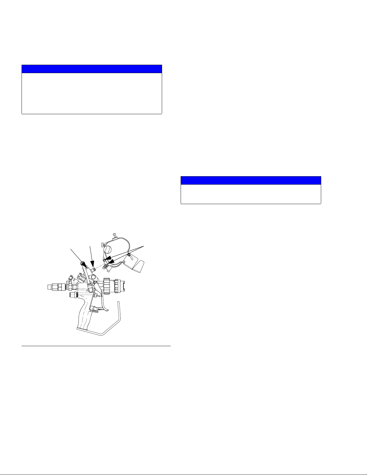
3. For guns with cutters, install cutter:
a. If necessary, use a crescent wrench to adjust
pivot (541) so that it is parallel to gun front end
and the open end points to the front of the gun.
See F
IG. 6.
e. Adjust cutter dispensing angle and chute angle
as desired.
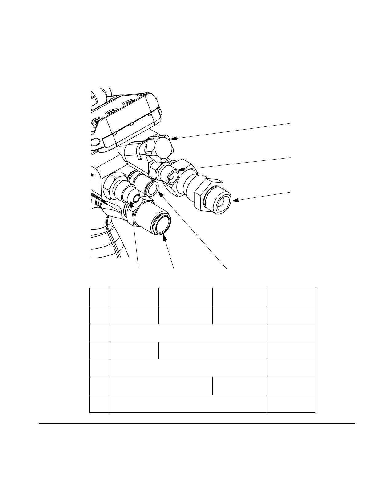
4. For internal mix guns, verify solvent knob (BD) is
adjusted to the fully closed position. See F
IG. 7 on
page 17.
5. Attach gun connections as described in F
IG. 7 on
page 17. See Techn ical Data on page 62 for fitting
sizes.
6. For internal mix guns, prime the solvent line. Turn
solvent adjustment knob (BD) until solvent discharges from the front of the gun. See F
IG. 7 on
page 17.
NOTICE
Internal mix guns: To prevent material curing inside
the gun, do not trigger gun if solvent is not primed.
NOTE: The recommended solvent line pressure is
80-100 psi (550-700 kPa, 5.5-7.0 bar).
541
F
IG. 6
b. Back out screws (630). See F
542
630
ti21008a
IG. 6.
c. Install cutter onto pivot so glass feed holes are
on top.
NOTE: Ensure proper engagement of o-ring (542) into
the cutter assembly. Verify there is no excess air leakage because it will greatly reduce the performance of
the air motor. See F
IG. 6.
d. Tighten screws (630) to lock cutter in place.
7. For guns with cutters, insert glass strands into
feed.
8. For guns with cutters, adjust anvil to blade tension. Refer to RS Gun Cutter Assemblies Operation-Repair for part identification:
a. Release lockdown.
b. Adjust tension knob as desired.
c. Tighten lockdown.
d. Release idler lock down.
e. Adjust idler lock down until it touches anvil.
f. Tighten idler lock down.
g. Perform test spray to verify proper cutting of
glass strands.
h. Adjust tension as necessary.
9. For external mix guns, adjust AAC knob (BD) to
middle of possible range of movement. See F
IG. 7
on page 17.
16 3A0232R
Page 17
10. Adjust AAC pressure on proportioner.
11. Perform test spray. Adjust system and gun settings
as necessary to get desired results.
Setup
BD
BC
BB
F
IG. 7: Fitting Details
258840_3A0232_2g
BF
BABE
Ref External Mix Internal Mix Chop Internal Mix Gel Fitting Size
BA
Atomized Air
(Catalyst)
Air Assist Contain-
ment (AAC)
Plugged 1/4 tube
BB Resin Inlet 1/4 NPSM
BC
Air Assist Con-
tainment (AAC)
Solvent 1/8 NPSM
BD Adjustment Knob --
BE Chop Air Inlet
Air Assist Contain-
ment (AAC)
3/8 tube
BF Catalyst Inlet #4 JIC
3A0232R 17
Page 18
Startup
Startup
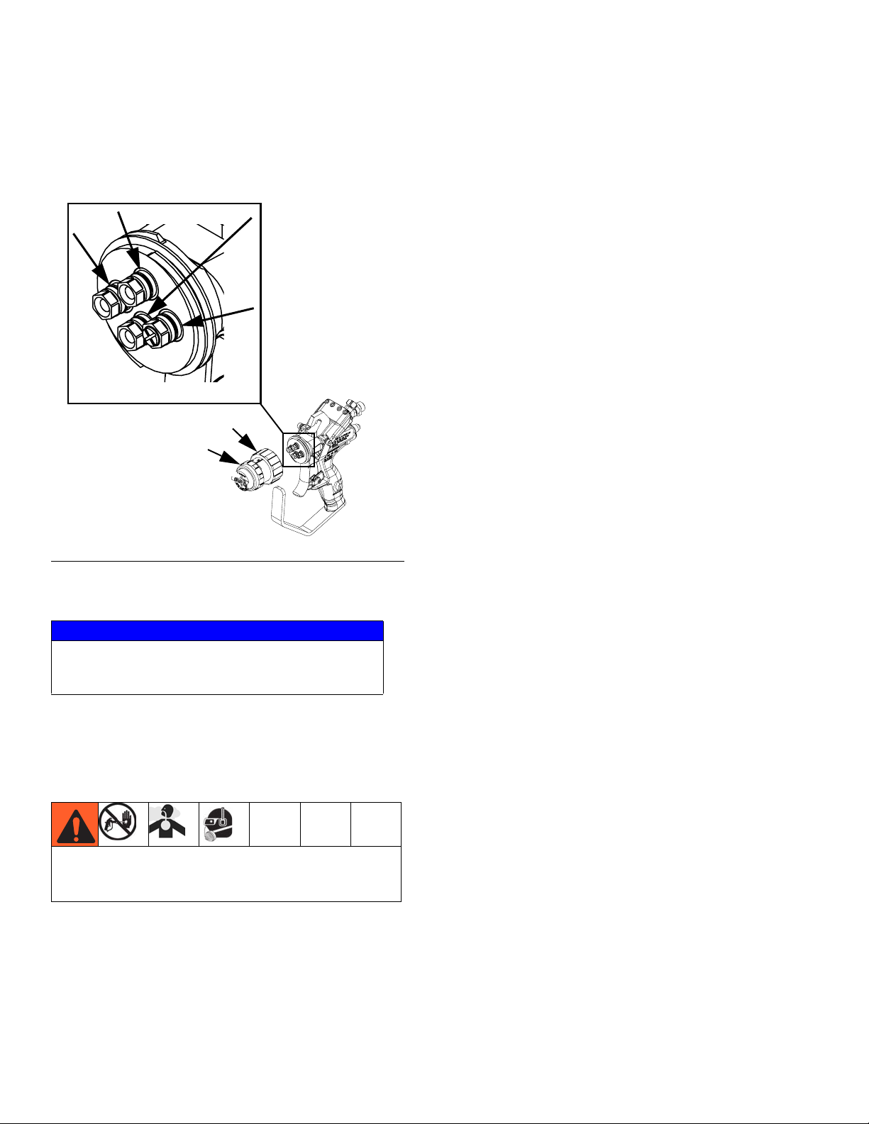
1. Inspect o-rings on housings. Replace as needed.
See F
IG. 8.
Housing O-rings
C
D
258840_3A0232_3g
F
IG. 8
2. Prime the system as required.
NOTICE
Gun damage can occur when the system is primed
with the front head installed. To avoid damage, only
prime the system with the front head removed.
3. Align front head with housings and install front head.
Tighten front head locking ring (C).
4. Verify air cap retaining ring (D) is tight.
Ensure locking ring (C) and retaining ring (D) are tight
before spraying. Spraying while either item is loose
may result in skin injection.
5. Verify fluid and air lines are at the desired pressures
then begin using the gun.
18 3A0232R
Page 19
Operation
High-pressure fluid from gun, hose leaks, or ruptured
components will pierce skin. This may look like just a
cut, but it is a serious injury that can result in amputation. Get immediate surgical treatment.
• Do not point gun at anyone or at any part of the
body.
• Do not put your hand over the dispense outlet.
• Do not stop or deflect leaks with your hand, body,
glove, or rag.
• Follow Pressure Relief Procedure when you
stop dispensing and before cleaning, checking, or
servicing equipment.
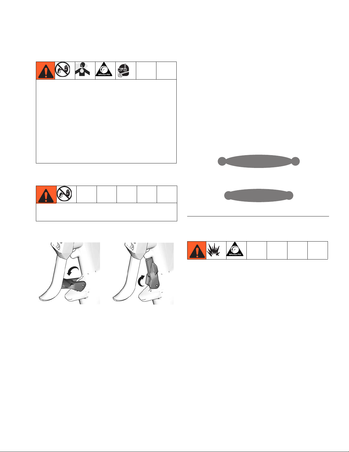
Tri gg er Lock
Operation
Adjust AAC
If the spray pattern is not even, the AAC air pressure
may need to be adjusted. For all guns, the AAC air pressure is set at the system. The external mix gun includes
an AAC air pressure adjustment on the gun also, see
AAC reference in F
pressure on the external mix gun, turn knob counter-clockwise. To decrease air pressure, turn knob clockwise. For large changes in AAC air pressure, adjust the
pressure at the system.
IG. 7 on page 17. To increase AAC air
Bad
Good
Engage trigger lock whenever you stop spraying to
avoid accidental triggering.
Engage
TI10442a
Disengage
TI10441a
FIG. 9
Internal Mix Flush
NOTE: The recommended solvent line pressure is
80-100 psi (550-700 kPa, 5.5-7.0 bar).
After spraying, open the solvent knob (BC) to allow solvent to flow through the gun. See F
While flushing, hold a metal part of the gun firmly to a
grounded metal pail.
IG. 7 on page 17.
3A0232R 19
Page 20
Pressure Relief Procedure
Pressure Relief
Procedure
1. Shutdown proportioner.
2. Relieve proportioner pressure. See proportioner
manual.
3. Engage gun trigger lock.
4. Close the bleed-type master air valve.
5. Disengage the trigger lock.
6. Hold a metal part of the gun firmly to a grounded
metal pail. Trigger the gun to relieve pressure.
7. Engage the trigger lock.
8. With a waste container in place, open all fluid drain
valves in the system. Leave drain valve(s) open until
you are ready to spray again.
9. If you suspect the spray tip or hose is clogged or
that pressure has not been fully relieved after following the steps above, VERY SLOWLY loosen retaining ring (D) or loosen hose end coupling to relieve
pressure gradually, then loosen completely. Clear
hose or tip obstruction. See F
part references.
IG. 1 on page 10 for
20 3A0232R
Page 21

Shutdown
Shutdown
Daily Shutdown
NOTICE
Failure to perform this procedure correctly and according to the prescribed schedule can result in poor mixing, fluid leaking, and cured material in or on the gun.
1. Perform Pressure Relief Procedure.
2. Solvent flush at 80-100 psi (550-700 kPa,
5.5-7.0 bar) for five seconds.
4. For internal mix guns, remove mixing element.
ti17896b
5. Remove front head.
ti17897b
3. Loosen then remove air cap retaining ring.
3A0232R 21
Page 22

Shutdown
6. Immerse front head, front cap, and the mixing element (internal mix guns only) in solvent. Use a
sealed container to prevent solvent evaporation.
NOTICE
Immersing the cutter assembly in solvent will damage
it and void the warranty.
ti17898a
NOTICE
In the following step, do not rinse catalyzed solvent
over the resin port. This may result in cured material.
8. Rinse excess resin from the resin port.
ti17900b
9. Lubricate the gun front face and check valve ports
with grease (Part No. 118665) as shown in the following illustration.
NOTICE
To prevent catalyst fumes from mixing with resin resulting in cured material, make sure to put grease in the
resin port.
7. Rinse front face of gun with clean solvent. Use a
squirt bottle or paint brush dipped in clean solvent.
ti17899b
ti17901b
22 3A0232R
Page 23

Shutdown
NOTICE
Failure to clean the surface between the trigger clamp
and the gun body can lead to material buildup preventing the clamp from seating properly resulting in material leakage from the front of the gun.
10. Wipe the trigger clamp assembly, actuator pins, and
surface between the trigger clamp and the gun body
with a rag to remove material. Use a compatible solvent.
Long-Term Shutdown
If gun will be unused for at least one week, perform this
long-term shutdown procedure.
1. Perform Daily Shutdown procedure, beginning on
page 21.
2. Flush System, see page 24.
ti17902a
3A0232R 23
Page 24

Maintenance
Maintenance
Flush System
NOTE:
• Flush before changing colors, before fluid can dry in
the equipment, before storing, and before repairing
equipment.
• Flush at the lowest pressure possible. Check connectors for leaks and tighten as necessary.
• Flush with a fluid that is compatible with the fluid
being dispensed and the equipment wetted parts.
NOTICE
Immersing the cutter assembly in solvent will damage
it and void the warranty.
1. Follow Pressure Relief Procedure, page 20.
2. Remove front head from gun and soak in solvent.
3. Place siphon tube in grounded metal pail containing
solvent.
4. Set pump to lowest possible fluid pressure then start
pump.
NOTE: The recommended solvent pressure during
flushing is 80-100 psi (550-700 kPa, 5.5-7.0 bar).
5. Hold a metal part of the gun firmly to a grounded
metal pail. Trigger the gun until clean solvent dispenses.
6. Perform Pressure Relief Procedure, page 20.
7. Remove gun from hose.
ti21012a
24 3A0232R
Page 25

Troubleshooting
Troubleshooting
See the troubleshooting procedures beginning on page
29 for additional troubleshooting help.
Problem Cause Solution
Catalyst leaking Trigger clamp assembly slipped See Fluid Leaking from Front of Gun on
page 29.
Catalyst hose loose Inspect and tighten
Catalyst fitting loose Inspect and tighten
Locking ring loose Clean and tighten
Air cap catalyst post o-ring damaged or
missing
Catalyst check valve housing o-rings missing or damaged
Needle assembly o-ring damaged or missing
Needle packing loose See Fluid Leaking from Under Trigger
Valve seat worn or damaged Inspect and replace if necessary
Valve seat seal damaged Inspect and replace if necessary
Resin leaking Trigger clamp assembly slipped or mis-
aligned
Resin hose loose Inspect and tighten
Resin fitting loose Inspect and tighten
Locking ring loose Clean and tighten
Air cap catalyst post o-ring damaged or
missing
Resin check valve housing o-rings missing
or damaged
Needle assembly o-ring damaged or missing
Needle packing loose See Fluid Leaking from Under Trigger
Valve seat worn or damaged Inspect and replace if necessary
Valve seat seal damaged Inspect and replace if necessary
Inspect and replace if necessary
Inspect and replace if necessary
Inspect and replace if necessary
Clamp Assembly on page 30
See Fluid Leaking from Front of Gun on
page 29.
Inspect and replace if necessary
Inspect and replace if necessary
Inspect and replace if necessary
Clamp Assembly on page 30
3A0232R 25
Page 26

Troubleshooting
Problem Cause Solution
Gun does not fully
actuate when triggered
Trigger clamp not opening properly Perform Adjust Trigger Clamp procedure on
page 29
Safety lock engaged Disengage safety lock
Trigger clamp pins bent Inspect and replace if necessary
Cutter air valve stuck Inspect and replace if necessary
Overspray on trigger clamp pins Clean and lubricate
Needle assembly stuck Check and adjust needle packing tension,
see Adjust Needle Packing Tension on
page 30
Hardened material in the needle/seat area Remove needle assembly, clean and replace if
necessary
Fluid does not spray
when trigger is fully
actuated
Proportioner off or in bypass mode Turn on proportioner and make ready to spray
Worn trigger clamp pins Inspect and replace if necessary
Worn trigger Inspect and replace if necessary
Loose trigger clamp assembly Inspect and torque as specified, see Adjust
Trigger Cl a m p on page 29
Misadjusted or missing actuator pin adjustment screws
If missing, replace screws.
If misadjusted, see Adjust Actuator Pin
Adjustment Screws, page 31.
Hardened material in front head (passageway and spray tip)
Check for blockage, perform Remove Hard-
ened Material from Internal Mix Front Head
on page 32 as necessary.
Hardened material in the needle/seat area Remove needle assembly, clean and replace if
necessary
Resin is present but
NO catalyst
No catalyst Check catalyst fluid level
Catalyst pump in bypass Turn on and make ready to spray
Trigger clamp out of phase 1) Adjust Trigger Clamp, page 29
2) Adjust Actuator Pin Adjustment Screws,
page 31
Actuator pin adjustment screw missing Replace then perform Adjust Actuator Pin
Adjustment Screws, page 31
Trigger worn Inspect and replace if necessary
Actuator pin worn Inspect and replace if necessary
Trigger clamp assembly loose Inspect and torque as specified, see Adjust
Trigger Cl a m p on page 29
Catalyst check valve stuck closed Inspect and replace if necessary
Hardened material in the needle/seat area Remove needle assembly, clean and replace if
necessary
26 3A0232R
Page 27

Problem Cause Solution
Catalyst is present
but no resin
No resin Check material fluid level
Trigger clamp out of phase 1) Adjust Trigger Clamp, page 29
2) Adjust Actuator Pin Adjustment Screws,
page 31
Catalyst pump in bypass Turn on and make ready to spray
Actuator adjustment screw missing Replace then perform Adjust Actuator Pin
Adjustment Screws, page 31
Trigger worn Inspect and replace if necessary
Actuator pin worn Inspect and replace if necessary
Trigger clamp assembly loose Inspect and torque as specified, see Adjust
Trigger Cl a m p on page 29
Hardened material in the needle/seat area Remove needle assembly, clean and replace if
necessary
Catalyst pressure
drops on initial trigger
Material continues to
spray after trigger is
released
Trigger clamp not opening evenly 1) Adjust Trigger Clamp, page 29
2) Adjust Actuator Pin Adjustment Screws,
page 31
Foreign object under trigger clamp Clean and replace if necessary
Overspray on trigger clamp pins Clean and lubricate
Actuator pins sticking Clean and replace if necessary
Needle packing too tight Check and adjust needle packing tension,
see Adjust Needle Packing Tension on
page 30
Material spraying out
AAC ports
Retaining ring not tight Tighten retaining ring
Cut or missing internal mix diffuser o-ring Inspect and replace if necessary
Cut or missing external mix check valve
Inspect and replace if necessary
o-ring
Internal mix check valve seat missing or
Inspect and replace if necessary
damaged or not tight
External mix check valve seat missing or
Inspect and replace if necessary
damaged or not tight
Material not mixed External mix catalyst tips plugged Clean and replace
Atomizing air pressure too low Adjust
Static mixer missing Replace, see Replace Internal Mix Element
on page 34.
Static mixer worn Inspect and replace if necessary, see Replace
Internal Mix Element on page 34.
Incorrect static mixer Replace if necessary, see Replace Internal
Mix Element on page 34.
AAC does not function
Air supply to gun is shut off Open air supply
Air regulator set incorrectly Adjust
Ports plugged Clean air capped or replace
AAC needle valve closed (external mix) Open AAC needle valve
Trigger clamp assembly loose Adjust Trigger Clamp, page 29
Troubleshooting
3A0232R 27
Page 28

Troubleshooting
Problem Cause Solution
No solvent Not enough solvent pressure Increase solvent pressure to the recommended
range of 80-100 psi (550-700 kPa, 5.5-7.0 bar).
No fluid in pressure pot Refill pressure pot
Output valve closed Open output valve
Check valve stuck closed Increase pressure in pressure pot
Material check valve plugged Clean and replace as needed
Solvent needle valve closed Open solvent needle valve
Solvent check valve stuck closed Ensure the solvent check valve opens freely
Solvent in catalyst/resin mix
Solvent needle valve open Close solvent needle valve
Solvent check valve o-ring damaged or
Inspect and replace if necessary
missing
Solvent valve damaged Inspect and replace if necessary
Resin in solvent line Solvent needle valve open Close solvent needle valve
Solvent check valve o-ring damaged or
Inspect and replace if necessary
missing
Solvent valve damaged Inspect and replace if necessary
AAC does not shut
AAC needle o-ring damaged (internal mix) Inspect and replace if necessary
off
Atomized catalyst air
does not shut off
Air leakage Air lines not fully seated in push lock tube
Atomized catalyst air needle o-ring damaged (external mix)
Inspect and replace if necessary
Ensure air lines are fully seated in fitting
fittings
Cutter assembly pivot tube o-ring damaged
Inspect and replace if necessary
or missing
AAC/Atomized catalyst external needle
Inspect and replace if necessary
o-ring damaged
Cutter air valve seat damaged Inspect and replace if necessary
G hook o-ring missing Inspect and replace if necessary
Cutter mount o-ring missing Inspect and replace if necessary
28 3A0232R
Page 29

Troubleshooting
Fluid Leaking from Front of Gun
To prevent skin injection, never use a gun that has a
resin and/or catalyst leakage.
Perform this procedure to find the source of the leakage
and to stop the leak.
1. Perform Adjust Trigger Clamp to attempt to fix the
leak.
2. If the leakage still exists:
a. Follow Pressure Relief Procedure, page 20.
b. Remove the leaking needle valve.
Adjust Trigger Clamp
To prevent skin injection, never use a gun that has a
resin and/or catalyst leakage.
NOTICE
Failure to perform this procedure correctly and when
required can result in poor mixing and fluid leaking.
Perform this procedure if there is fluid leakage from the
front of the gun or if the gun is out of phase. This procedure. See F
IG. 10.
113
111
216
D
F
115,
215
ti17903a
c. Verify no obstruction between the ball and seat.
Clean as necessary.
d. If the resin side is leaking, use a 9/64 in.
allen-wrench to remove the seat.
e. If the catalyst side is leaking, use a 0.093 in.
allen wrench to remove the seat.
f. Verify the seat surface is free of wear and
scratches.
g. If wear or scratches are found on the seat, dis-
card defective seat and replace with new seat.
h. Install seat.
i. Install valve.
j. See Adjust Trigger Clamp on page 29 to install
and adjust the trigger clamp.
F
IG. 10: External Mix shown
1. Perform Pressure Relief Procedure, page 20.
2. Engage trigger lock.
3. Loosen four screws (113).
4. While pressing the trigger clamp assembly (111)
firmly against the gun body, tighten the four
screws (113) in the following sequence:
a. Tighten the two inside screws to 25 in-lb
(2.8 N•m).
NOTE: Do not overtighten the two outside screws as
this may cause leakage.
b. Tighten the two outside screws to 10 in-lb
(1.1 N•m).
5. Loosen front head locking ring (C) then remove front
head assembly (F).
6. Pressurize the resin and catalyst fluid lines to operating pressures and verify there is no leakage.
k. Install front head assembly (F).
3A0232R 29
Page 30

Troubleshooting
Fluid Leaking from Under Trigger Clamp Assembly
1. Follow Pressure Relief Procedure, page 20.
2. Remove trigger clamp assembly (A).
A
3. Tighten packing nut (906).
c. Discard the o-ring (909) if wear or damage is
found.
d. Reassemble the needle assembly.
e. Install the needle assembly into the gun.
f. See Adjust Trigger Clamp on page 29 to install
and adjust the trigger clamp.
Adjust Needle Packing Tension
If there is a fluid leak at the rear of the needle assembly,
the packings can be tightened to stop the leak.
1. Follow Pressure Relief Procedure, page 20.
2. Loosen four screws (113) then remove trigger clamp
assembly (111). See page 38.
ti17903a
4. If the leakage stopped, see Adjust Trigger Clamp
on page 29 to install and adjust the trigger clamp.
5. If the leakage still exists:
a. Disassemble the needle assembly.
b. Discard the packing disk (904).
906
901
907
905
904
903
902
909
908
ti16592a
3. Use 7/16 in. wrench to tighten packing nut (906)
1/8th of a turn.
4. Re-pressurize and re-check for leaks in rear of needle. If leak remains, packings may need to be
replaced. If necessary, see Replace Needle Pack-
ing on page 37.
5. Ensure needle flats are aligned with one another.
6. Install trigger clamp assembly on gun then perform
Adjust Trigger Clamp procedure on page 29.
7. Trigger gun to check for smooth operation of material needles. If material needles do not operate
smoothly, packings may need to be replaced.
NOTICE
Be careful not to overtighten trigger clamp assembly
as this will cause the material needles to bind and
cause material needles to operate incorrectly.
Beveled edge must face
rear of needle
30 3A0232R
Page 31

Troubleshooting
Adjust Actuator Pin Adjustment Screws
Perform this procedure if the trigger clamp pulls away
from the gun body unevenly when the trigger is pulled,
see F
IG. 12. This procedure adjusts the actuator
pins (111) in the trigger clamp, see F
When the trigger is pulled, it moves the trigger clamp
assembly resulting in fluid flow from each component.
NOTE: The actuator pins are factory set. If the trigger,
trigger clamp assembly, or pins are removed the trigger
may need to be adjusted.
NOTE: When installing the four finger trigger (16F627),
ensure trigger lock functions and clamp assembly opens
correctly, see F
perform this Adjust Actuator Pin Adjustment Screws
procedure.
1. Perform Pressure Relief Procedure, page 20.
IG. 11.
IG. 12. If any adjustments are needed
7. Adjust each screw until the actuator pin just begins
to touch the trigger. This can be verified by the trigger just beginning to lift off of the trigger lock.
8. Back each screw out 1/2 turn.
9. Disengage trigger lock.
10. While watching the trigger clamp assembly, trigger
the gun to verify both sides of the trigger clamp
assembly pull away from the gun body at the same
time.
Bad
Uneven
F
IG. 12
Good
Even
2. Engage trigger lock.
3. Use 5/64 in. allen key to remove adjustment
screws (114).
114
111
FIG. 11
4. Apply medium strength thread sealant to threads of
screws.
5. Install adjustment screws (114) into trigger clamp
assembly (111).
6. Squeeze trigger so that it touches the trigger lock. If
trigger cannot touch trigger lock, back out adjustment screws until trigger touches the trigger lock.
11. Hold the trigger fully engaged and measure the
space between the trigger clamp and the gun body
on both sides. The gaps should be at least 0.065 in.
(1.65 mm) in the open position. Adjust screws as
necessary. See F
IG. 12.
3A0232R 31
Page 32

Repair
Repair
Remove Hardened Material from Internal Mix Front Head
802
801
804
803
805
816*
806*
810
808
* Parts shown are not
available on internal mix,
high flow front heads
F
IG. 13
Perform this procedure when the internal mix diffuser
assembly is filled with cured material. When this happens, the diffuser assembly must be drilled out.
1. Perform Pressure Relief Procedure, page 20.
2. Loosen then remove retaining ring (810) and air cap
assembly (808) from head (801).
3. Remove diffuser assembly (803).
4. Use two wrenches on flats of diffuser and cap (806)
to remove cap.
5. Use punch to break the check valve (812) and valve
seat (816) loose from the hardened material. Discard the valve seat and spring (813).
812*
813*
6. Use punch to break hardened material loose from
the diffuser cap (806).
32 3A0232R
Page 33

Repair
7. For standard 1/4 in. mixers, use a 0.152 in. drill in
the diffuser assembly outlet to remove hardened
material.
For high flow 3/8 in. mixers, use a 0.161 in. drill.
Outlet
ti17687a
F
IG. 14
8. For 1/4 in. mixers, use a 0.246 in. drill in the diffuser
assembly inlet to remove hardened material.
For 3/8 in. mixers, use a 0.359 in. drill.
Inlet
12. Install check valve (812) and new spring (813) into
the seat then install cap (806). See F
IG. 18 for orien-
tation of parts.
NOTE: Parts shown are
not available on internal
mix, high flow front
heads
FIG. 16
13. Remove and inspect o-ring (804). Replace if worn
or damaged.
14. Lubricate o-ring and install onto diffuser. Install diffuser into head.
15. Torque cap to 23-27 in-lb (2.6-3.1 N•m).
16. Install diffuser into head (801).
ti17688a
F
IG. 15
9. Use a pick to remove any cured material from the
front air cap (808).
10. Install new mix element into diffuser (803).
11. Install new check valve seat (816) into diffuser. See
F
IG. 16 for seat orientation.
17. Install air cap assembly and tighten retaining ring.
3A0232R 33
Page 34

Repair
Replace Internal Mix Element
802
801
804
* Parts shown are not
available on internal mix,
high flow front heads
803
805
816*
806*
810
808
812*
813*
FIG. 17
See internal mix front head parts list on page 50 for
available kits.
NOTICE
There is a half-moon pin pressed into the front
head (801) behind the diffuser assembly (803). Do not
attempt to remove this pin. Removal will result in poor
mixing.
1. Perform Pressure Relief Procedure, page 20.
2. Remove retaining ring (810) and air cap
assembly (808) from head (801).
3. Remove diffuser assembly (803).
4. Use two wrenches on flats of diffuser and cap (806)
to remove cap. Spring (813) and check valve (812)
will fall out when cap is removed.
5. Use a small hex key in the small hole in the back of
the diffuser to push the mix element (805) and
check valve seat (816) out.
6. Install new mix element into diffuser (803).
7. Install check valve seat (816) into diffuser. See F
17 for seat orientation.
IG.
8. Install check valve (812) and spring (813) into the
seat then install cap (806). See F
tion of parts.
NOTE: Parts shown are
not available on internal
mix, high flow front
heads
FIG. 18
9. Remove and inspect o-ring (804). Replace if worn
or damaged.
10. Lubricate o-ring and install onto diffuser. Install diffuser into head.
11. Torque cap to 23-27 in-lb (2.6-3.1 N•m).
12. Install diffuser into head (801).
13. Install air cap assembly and tighten retaining ring.
IG. 18 for orienta-
34 3A0232R
Page 35

Replace External Mix Check Valve and O-Rings
702
701
717
703
704
718
705
706
710
Repair
709
FIG. 19
See Front Head Assemblies beginning on page 49 for
available kits.
1. Perform Pressure Relief Procedure, page 20.
2. Remove retaining ring (710) and air cap
assembly (709) from head (701).
3. Remove check valve assembly (703).
4. Use two wrenches on flats of seal (703) and check
valve cap (706) to remove cap. Spring (705) and
ball (704) will fall out when cap is removed.
5. Remove and inspect o-ring (717) and washer (718).
Replace if worn or damaged.
6. Lubricate o-ring and install onto check valve
assembly (703).
7. Install washer (718), ball (704), and spring (705)
into check valve seal (703) then install check valve
cap (706) onto check valve seal finger-tight.
10. Install air cap onto head and tighten retaining
ring (710).
NOTICE
To prevent distorting the end of the cap (706), do
not over-tighten the check valve assembly.
8. Use two wrenches on flats of seal (703) and check
valve cap (706) to torque check valve cap onto
check valve seal to 23-27 in-lb (2.6-3.1 N•m).
9. Install check valve assembly into head. See F
for assembly orientation.
3A0232R 35
IG. 19
Page 36

Repair
Replace Material Needle Assembly
NOTE: The material needle assemblies are the two side
needles (105) in the rear of the gun. See page 38.
1. Follow Pressure Relief Procedure, page 20.
2. Loosen four screws (113) then remove trigger clamp
assembly (111). See page 38.
3. Use 1/2 in. deep well socket to break loose and
remove material needle assemblies.
4. Install new material needle assemblies.
5. Ensure needle flats are aligned with one another.
6. Install trigger clamp assembly on gun then perform
Adjust Trigger Clamp procedure on page 29.
Replace Center Needle Assembly
1. Follow Pressure Relief Procedure, page 20.
2. Loosen four screws (113) then remove trigger clamp
assembly (111). See page 38.
3. Use 7/32 in. deep well socket to remove
retainer (108) then remove the needle (106),
spring (107), and o-ring (110).
4. Install new o-ring. Verify needle is clean before reinstalling. Use a liberal amount of lubrication.
5. Install rear packing retainer with a liberal amount of
lubrication.
NOTICE
Be careful not to overtighten trigger clamp assembly as this will cause the material needles to bind
and cause material needles to operate incorrectly.
36 3A0232R
Page 37

Replace Needle Packing
NOTE: The needle packing is the seal (904) inside the
needle assembly (105). See pages 38 and 52.
NOTICE
Needles bend easily. To prevent bending and damaging the needles, be careful when using wrenches to
remove the needle packings.
1. Follow Pressure Relief Procedure, page 20.
2. Use 9/64 in. hex key to loosen the four screws (114)
on trigger clamp (111). Remove clamp. See
page 38.
Repair
3. Use 7/16 in. wrench to break loose then remove the
packing nuts (906). See page 52.
4. Remove needle (908).
5. Remove old packing from needle.
6. Liberally lubricate the new packing with grease
(Part No. 118665).
7. Install new packing onto needle. Install packing with
beveled edge facing rear of needle.
8. Install needle.
9. Install packing nuts and torque to 30 in-lb (3.4 N•m).
10. Ensure needle flats are aligned with one another.
11. Slide trigger clamp onto gun then, with the trigger
clamp loose, perform Adjust Trigger Clamp proce-
dure on page 29.
NOTICE
Be careful not to overtighten trigger clamp assembly
as this will cause the material needles to bind and
cause material needles to operate incorrectly.
3A0232R 37
Page 38

Parts
Parts
External Mix Gel Gun, 258840
129
130
133
160
131
134
114
106
138
153
127
132
128
113
111
112
109
108
107
105
110
139
141
104
134
143
116
116a
115b
115
115a
136
135
103
102
159
126
122
123
124
119
101
118
125
152
120
117
155
ti21015a
121
38 3A0232R
Page 39

Ref Part Description Qty
100 199360 DOCUMENT, declaration 1
101 24N711 HANDLE, gun 1
102†‡ 24E428 SEAL, needle, seat (pack of 6) 2
103‡ 16C104 RETAINER, seat, needle valve,
resin
24M833 OPTIONAL - RETAINER, seat,
needle valve, resin, carbide
104† 24D201 RETAINER, seat, catalyst 1
105** 24E417 NEEDLE, assembly 2
106❄ 16C101 NEEDLE, aac 1
107❄ 123633 SPRING, needle assembly 1
108❄ 16C100 RETAINER, aac 1
109❄ 24E429 O-RING (pack of 6) 1
110❄ 24E430 O-RING (pack of 6) 1
111◆ 16C098 CLAMP, trigger, top 1
112◆ 16C099 CLAMP, trigger, bottom 1
113◆ 124057 SCREW, cap, sh 4
114◆ GC2082 SCREW, set, flpt 2
115❖ 24E423 HOUSING, check valve asm,
catalyst
115a 123934 O-RING, FKM (smaller o-ring in
housing)
115b 112319 O-RING (larger o-rings on
outside of housing)
116❖ 24E424 HOUSING 3
116a 112319 O-RING 6
117 24E427 HEAD, asm, ext mix, vert 1
118 16C705 PLUG, trigger 1
119 111316 PACKING, o-ring 1
120✿ 179737 PIN, actuator 2
121✿ 16C085 TRIGGER, gun, 2-finger 1
121a 16F627 TRIGGER, 4-finger (not shown) 1
122✿ 123733 BOLT, shoulder, self locking 2
123 276745 STOP, trigger 1
124 112033 PIN, dowel 1
125 16C130 GUARD, trigger 1
126 111945 SCREW, cap, fl hd 2
127 16C107 FITTING, resin hose 1
128* 16C118 FITTING, solvent 1
129* 16C117 VALVE, solvent 1
130* 24E437 PACKING, o-ring (pack of 6) 1
131* 24E431 O-RING (pack of 6) 1
132* 24E432 RING, retaining, e-ring
(pack of 6)
133* 16C119 FITTING, insert, solvent 1
134* 111450 PACKING, o-ring 2
135 123737 FITTING, tube, push connector 1
136 123736 FITTING, tube, push connector 1
138★ 16C108 FITTING, catalyst hose 1
Ref Part Description Qty
139 16C279 BODY, gel gun mount 1
141 123909 SCREW, cap, sh 2
143 124282 SCREW, set 1
148 24F007 KIT, tool, hex keys, gun 1
152 126395 SCREW, set, flat point 1
1
153★ 16D039 RESTRICTOR, catalyst 1
154▲ 222385 TAG, skin injection warning and
note to physician
155 CST521 TIP, spray, 521 1
158▲ 16P319 LABEL, quick start, RS gun 1
159 295662 PLUG, pipe 1
160 189018 SWIVEL 1
* Parts included in Solvent/AAC assembly kit 24E415.
† Parts included in catalyst seat kit 24E420.
‡ Parts included in resin seat kit 24E421.
◆ Parts included in needle clamp kit 24E416.
❄ Parts included in AAC needle kit 24E419.
1
★ Parts included in catalyst fitting kit 24H269.
✿ Parts included in gun trigger kit 24H268.
1
** Kit 24E436 includes 6 needle assemblies.
2
❖ O-rings on housings are available in kit 257425.
▲ Replacement Danger and Warning labels, tags, and
cards are available at no cost.
1
Parts
1
3A0232R 39
Page 40

Parts
Internal Mix Gel Gun, 258853
233
234
260
237
229
214
227
235
238
230
231
203
228
202
232
236
213
211
212
206
205
204
When converting an Internal Gel gun
to an Internal Chop gun, replace top
housing with 24M045.
215b
217
217a
239
240
222
201
216
216a
234
244
215
215a
217b
259
222
226
241
224
223
225
219
220
218
254
ti21016a
221
40 3A0232R
Page 41

Ref Part Description Qty
200 199360 DOCUMENT, declaration 1
201 24N711 HANDLE, gun 1
202†‡ 24E428 SEAL, needle, seat (pack of 6) 2
203‡ 16C104 RETAINER, seat, needle valve,
resin
24M833 OPTIONAL - RETAINER, seat,
needle valve, resin, carbide
204† 24D201 RETAINER, seat, catalyst 1
205** 24E417 NEEDLE, assembly 2
206 GC2241 SCREW, set 1
211◆ 16C098 CLAMP, trigger, top 1
212◆ 16C099 CLAMP, trigger, bottom 1
213◆ 124057 SCREW, cap, sh 4
214◆ GC2082 SCREW, set, flpt 2
215❖ 24G764 HOUSING, check valve asm,
catalyst
215a 123934 O-RING, FKM (smaller o-ring in
housing)
215b 112319 O-RING (larger o-rings on outside
of housing)
216❖ 24E424 HOUSING 2
216a 112319 O-RING 6
217❖ 24H270 HOUSING, check valve asm,
solvent
217a 123934 O-RING, FKM (smaller o-ring in
housing)
217b 112319 O-RING (larger o-rings on outside
of housing)
218 24G615 HEAD, asm, internal mix, gel 1
219 16C705 PLUG, trigger 1
220✿ 179737 PIN, actuator 2
221✿ 16C085 TRIGGER, gun, 2-finger 1
221a 16F627 TRIGGER, 4-finger (not shown) 1
222✿ 123733 BOLT, shoulder, self locking 2
223 276745 STOP, trigger 1
224 112033 PIN, dowel 1
225 16C130 GUARD, trigger 1
226 111945 SCREW, cap, fl hd 2
227 16C107 FITTING, resin hose 1
228* 16C118 FITTING, solvent 1
229* 16C117 VALVE, solvent 1
230* 24E437 PACKING, o-ring (pack of 6) 1
231* 24E431 O-RING (pack of 6) 1
232* 24E432 RING, retaining, e-ring (pack of 6) 1
233* 16C119 FITTING, insert, solvent 1
234* 111450 PACKING, o-ring 2
235 123737 FITTING, tube, push connector 1
236 116134 PLUG, pipe, headless 1
Ref Part Description Qty
237★ 16D039 RESTRICTOR, catalyst 1
238★ 16C108 FITTING, catalyst hose 1
239 16C279 BODY, gel gun mount 1
240 123909 SCREW, cap, sh 2
241 111316 PACKING, o-ring 1
1
244 124282 SCREW, set 1
249 24F007 KIT, tool, hex keys, gun 1
254 CST521 TIP, spray, 521 1
257▲ 222385 TAG, skin injection warning and
note to physician
258▲ 16P319 LABEL, quick start, RS Gun 1
259 295662 PLUG, pipe 1
260 189018 SWIVEL 1
* Parts included in Solvent/AAC assembly kit 24E415.
† Parts included in catalyst seat kit 24E420.
1
‡ Parts included in resin seat kit 24E421.
◆ Parts included in needle clamp kit 24E416.
1
★ Parts included in catalyst fitting kit 24H269.
2
✿ Parts included in gun trigger kit 24H268.
❖ O-rings on housings are available in kit 257425.
** Kit 24E436 includes 6 needle assemblies.
1
▲ Replacement Danger and Warning labels, tags, and
1
cards are available at no cost.
2
Parts
1
3A0232R 41
Page 42

Parts
External Mix Chop Gun with Cutter, 258970
Ref Part Description Qty
301 258852 GUN, external mix, chop 1
302 24E512 CUTTER ASSEMBLY, external mix 1
303 16P320 LABEL, quick start, RS gun 1
Internal Mix Chop Gun with Cutter, 258971
Ref Part Description Qty
401 258854 GUN, internal mix, chop 1
402 24P681 CUTTER ASSEMBLY, internal mix 1
303 16P320 LABEL, quick start, RS gun 1
Internal Mix, High Flow, Chop Gun with Cutter, 24P435
Ref Part Description Qty
501 24P436 GUN, internal mix, chop, high flow 1
402 24P681 CUTTER ASSEMBLY, internal mix 1
303 16P320 LABEL, quick start, RS gun 1
301, 401, 501
302, 402
ti21017b
External Mix Chop Gun shown
42 3A0232R
Page 43

Chop Guns
External Mix Chop Gun, 258852
Parts
567
529
533
534
538
514
527
530
506
563
531
505
536
532
535
528
503
502
513
511
508
512
509
559
546
507
558
534
504
502
543
539
545
549
516a1
501
541
520
560
542
540
516a
515b
515
515a
564
563
526
510
522
524
548
523
517
561
518
521
525
ti17943b
3A0232R 43
Page 44

Parts
Internal Mix Chop Gun, 258854
563
533
529
534
567
514
537
530
538
531
505
527
532
536
528
506
535
513
503
510
511
502
512
509
508
543
546
507
559
504
540
545
502
549
558
539
534
501
560
541
542
516a
516a1
516b2
515b
515
516b1
515a
516b
564
563
522
526
524
523
548
525
518
520
517
561
521
ti21018a
44 3A0232R
Page 45

High Flow Internal Mix Chop Gun, 24P436
563
Parts
533
529
534
567
537
514
530
538
505
527
531
532
528
536
535
506
503
513
510
511
502
512
509
508
543
546
507
559
504
540
545
502
549
558
539
534
501
560
541
516a
542
516b
516a1
516b2
515b
515
515a
516b1
564
522
517
524
548
561
563
523
518
526
525
3A0232R 45
520
521
ti21019a
Page 46

Parts
External Mix, Internal Mix, and Internal Mix High Flow Chop Gun Parts
Quantity
Ref Part Description
500 199360 DOCUMENT, declaration 1 1 1
501 24N711 HANDLE, gun 1 1 1
502†‡ 24E428 SEAL, needle, seat (pack of 6) 2 2 2
503 16C104‡ RETAINER, seat, needle valve, resin 1 1
24M833 RETAINER, seat, needle valve, resin, carbide
505** 24E417 NEEDLE, assembly 2 2 2
506 ❄ 16C101 NEEDLE, aac 1 1 1
507❄ 123633 SPRING, needle assembly 1 1 1
508❄ 16C100 RETAINER, aac 1 1 1
509❄ 24E429 O-RING (pack of 6) 1 1 1
510❄ 24E430 O-RING (pack of 6) 1 1 1
511✿ 16C098 CLAMP, trigger, top 1 1 1
512✿ 16C099 CLAMP, trigger, bottom 1 1 1
513✿ 124057 SCREW, cap, sh 4 4 4
514✿ GC2082 SCREW, set, flpt 2 2 2
515✠ 24G764 HOUSING, check valve, catalyst 1 1
24E423 HOUSING, check valve, catalyst 1
515a 123934 O-RING, FKM (smaller o-ring in housing) 1 1 1
515b 112319 O-RING (larger o-rings on outside of housing) 2 2 2
516a✠ 24E424 HOUSING 3 2 2
516a1 112319 O-RING 1 1 1
516b✠ 24H270 HOUSING, check valve asm, solvent 1 1
516b1 123934 O-RING, FKM (smaller o-ring in housing) 1 1 1
516b2 112319 O-RING (larger o-rings on outside of housing) 2 2 2
517 24E426 HEAD, external mix, horizontal 1
24E442 HEAD, internal mix, chop 1
24P562 HEAD, internal mix, chop, high flow 1
517a 123934 O-RING, FKM (smaller o-ring in housing) 1 1 1
517b 112319 O-RING (larger o-rings on outside of housing) 2 2 2
518 24E425 VALVE, air, assy, trigger 1 1 1
520❖ 179737 PIN, actuator 2 2 2
521❖ 16C085 TRIGGER, gun, 2-finger 1 1 1
521a 16F627 TRIGGER, 4-finger (not shown) 1 1 1
522❖ 123733 BOLT, shoulder, self locking 2 2 2
523 276745 STOP, trigger 1 1 1
524 112033 PIN, dowel 1 1 1
525 16C130 GUARD, trigger 1 1 1
526 111945 SCREW, cap, fl hd 2 2 2
527 16C107 FITTING, resin hose 1 1 1
528* 16C118 FITTING, solvent 1 1 1
529* 16C117 VALVE 1 1 1
530* 24E437 PACKING, o-ring (pack of 6) 1 1 1
531* 24E431 O-RING (pack of 6) 1 1 1
532* 24E432 RING, retaining, e-ring (pack of 6) 1 1 1
533* 16C119 FITTING, insert, solvent 1 1 1
534*◆ 111450 PACKING, o-ring 2 2 2
535 123737 FITTING, tube, push connector 1 1 1
536 123736 FITTING, tube, push connector 1 1 1
537★ 16D039 RESTRICTOR, catalyst 1 1
538★ 16C108 FITTING, catalyst hose 1 1 1
258852 258854 24P436
1
46 3A0232R
Page 47

Quantity
Ref Part Description
539◆ 16C103 BODY, chopper mount 1 1 1
540◆ 16C120 ADAPTER, chopper rotation 1 1 1
541◆ 16F501 TUBE, air pivot 1
24F997 TUBE, air pivot 1 1
542◆ 24E433 PACKING, o-ring (pack of 6) 1 1 1
543◆ 123909 SCREW, cap, socket head 2 2 2
544 239663 SWIVEL, straight 1 1 1
545◆ 124397 SPRING, belleville 1 1 1
546◆ C19080 SCREW, cap, hex head 1 1 1
548 124058 SPRING, compression 1 1 1
549 124282 SCREW, set, cppt 1 1 1
554 24F008 KIT, tool, hex keys, chop 1 1 1
558◆ 16F500 EXTENSION, cutter 1 1 1
559◆ 295662 PLUG, pipe 1 1 1
560 126395 SCREW, set, flat point 1 1 1
561 CST443 TIP, spray, 443 1 1 1
562▲ 222385 TAG, skin injection warning and note to
physician
563 125412 FITTING, elbow, male, swivel 2 2 2
564 125473 TUBE, pneumatic, polyurethane 1 1 1
567 189018 SWIVEL 1 1 1
258852 258854 24P436
1 1 1
* Parts included in solvent/AAC assembly kit 24E415.
Parts
† Parts included in catalyst seat kit 24E420.
‡ Parts included in resin seat kit 24E421.
✿ Parts included in needle clamp kit 24E416.
❄ Parts included in AAC needle kit 24E419.
** Kit 24E436 includes 6 needle assemblies.
★ Parts included in catalyst fitting kit 24H269.
❖ Parts included in gun trigger kit 24H268.
✠ O-rings on housings are available in kit 257425.
▲ Replacement Danger and Warning labels, tags, and
cards are available at no cost.
◆ Parts included in Cutter Adapter Kits, page 48.
3A0232R 47
Page 48

Parts
Cutter Adapter Kits
External Mix Cutter Adapter Kit, 24E422 ★
Internal Mix Cutter Adapter Kit, 24G832
Internal Mix Adapter External Mix Adapter
ti21020a
These kits provide replacement parts for the cutter
adapter.
To convert an external mix gel gun to an external mix
chop gun, see External Mix Gel Gun to Chop Gun
Conversion on page 55. The internal mix gel gun cannot be converted to a chop gun.
★ For single strand, external mix chop, low pressure
applications, an external mix cutter extension adapter kit
may be purchased in addition to the external mix cutter
adapter kit. See External Mix Chopper Extension Kit,
24V096, page 56.
48 3A0232R
Page 49

Front Head Assemblies
External Mix Horizontal Spray Pattern Front Head, 24E426
External Mix Vertical Spray Pattern Front Head, 24E427
702
701
708
708a
705
706
713
Parts
708a
709
712
711
717
703
704
718
Ref Part Description Qty
701
702 16C220 RING, locking 1
703*
704*†
705*†
706*
708
708a 111504 O-RING 3
709★ 262699 AIR CAP, vertical
710✿❄★
711 GC2081 SCREW, set, flat point 1
712✿❄★
713✿❄★ 107313 PACKING, o-ring 1
717*† 113137 PACKING, o-ring 1
718*†
* Parts available in external mix front head check valve
262696
16C489
M72843
123743
16C490
262697
❄ 262700 AIR CAP, horizontal
16E378
15G998
168588
kit 24E446.
HEAD, spray, external mix 1
SEAL, tip, external mix 1
BALL, sst 1
SPRING, compression 1
CAP, check valve, external mix 1
INSERT, valve assist, asm, ext
mix
(Model 24E427 only)
(Model 24E426 only)
RING, retaining 1
WASHER 1
WASHER, non-metallic 1
1
1
1
710
† Parts available in external mix front head check valve
repair kit 24E447.
✿ Parts included in retaining ring kit 24H274.
❄ Parts included in horizontal air cap kit 24H275.
★ Parts included in vertical air cap kit 24H283.
3A0232R 49
Page 50

Parts
Internal Mix Gel Front Head, 24G615
Internal Mix Chop Front Head, 24E442
NOTICE
There is a half-moon pin pressed into the front
head (801) behind the diffuser assembly (803). Do not
attempt to remove this pin. Removal will result in poor
mixing.
802
801
804
805
803
816
813
811
808
809
810
812
Part orientation detail
Ref Part Description Qty
801 262703 HEAD, spray, internal 1
802 16C220 RING, locking 1
803 16C327 DIFFUSER, internal mix 1
804 113746 PACKING, o-ring 1
805* 16C300 ELEMENT, mixing, internal mix 1
806* 16C397 CAP, check valve, internal mix 1
808❄ 262701 AIR CAP, asm, internal mix,
chop (Model 24E442 only)
★ 262702 AIR CAP, asm, internal mix, gel
coat (Model 24G615 only)
809✿❄★ 15G998 WASHER 1
810✿❄★ 16E376 RING, retaining 1
811✿❄★ 107313 PACKING, o-ring 1
812*† 16C408 VALVE, check, internal mix 1
813*† 123734 SPRING, compression 1
816*† 16F323 SEAT, check valve, int mix 1
806
* Parts available in internal mix front head check valve
kit 24E443.
† Parts available in internal mix check valve spring kit
24E444.
✿ Parts included in retaining ring kit 24H274.
❄ Parts included in internal mix chop air cap kit
1
1
24H277.
★ Parts included in internal mix gel air cap kit 24H278.
50 3A0232R
Page 51

Internal Mix, High Flow Chop Front Head, 24P562
NOTICE
There is a half-moon pin pressed into the front
head (801) behind the diffuser assembly (803). Do not
attempt to remove this pin. Removal will result in poor
mixing.
802
801
803
804
805
Parts
811
808
809
810
✿ Parts included in retaining ring kit 24H274.
Ref Part Description Qty
801 262703 HEAD, spray, internal 1
802 16C220 RING, locking 1
803 16G806 DIFFUSER, internal mix, 3/8 1
804 113746 PACKING, o-ring 1
805 20310-90 ELEMENT, mixing, spiral 1
808❄ 262701 AIR CAP, asm, internal mix,
chop (Model 24E442 only)
★ 262702 AIR CAP, asm, internal mix, gel
coat (Model 24G615 only)
809✿❄★ 15G998 WASHER 1
810✿❄★ 16E376 RING, retaining 1
811✿❄★ 107313 PACKING, o-ring 1
3A0232R 51
❄ Parts included in internal mix chop air cap kit
24H277.
★ Parts included in internal mix gel air cap kit 24H278.
1
1
Page 52

Parts
Needle Assembly, 24E417
902
909
908
906
901
907
905
904
903
ti16592a
Beveled edge must face rear of needle
Ref Part Description Qty
901 123634 SPRING, needle assembly 1
902 16C080 HOUSING, needle packing 1
903* 16C081 RETAINER, packing 1
904* 24H279 PACKING, disk (pack of 6) 1
905* 16C083 RETAINER, packing 1
906 16C086 NUT, packing material 1
907* 16C087 CLIP, retainer 1
908 24C780 NEEDLE, assembly 1
909* 24H281 O-RING (pack of 6) 1
* Parts included in needle repair kit 24E418.
52 3A0232R
Page 53

O-ring Identification
The following illustration shows all available o-rings at
actual size. See the respective illustration in the Parts
section beginning on page 38 for part references and
locations.
White (PTFE) O-rings
Parts
131, 231, 531
110, 510
109, 509
130, 230, 530
708a
Part of:
215, 216, 217,
115, 116
713, 811
637
Black (FKM) O-rings
717
119, 241
804
909
638
542
603
134, 234, 534
3A0232R 53
Page 54

Accessories
Accessories
Fusion® Grease
118665, 4 oz. (113 gram)
High adhesion, water resistant, lithium-based lubricant.
Use this to lubricate the gun. MSDS sheets available at
www.graco.com.
INDy or Formula Adapter Kit, 125797
Ideal for mounting an RS gun in place of an INDy or Formula gun. Kit includes the necessary items to connect
the RS gun to the connections used by INDy and Formula guns.
LPA2 Adapter Kit, 125843
Ideal for mounting an RS gun in place of an LPA2 gun.
Kit includes the necessary items to connect the RS gun
to the connections used by the LPA2 gun.
NOTE: An air assist tube and a catalyst hose are
required to mount the RS gun in place of the LPA2 gun
but they are not included in this kit. The existing air
assist tube or catalyst hose may be able to be re-used.
See the following table if additional parts are needed.
Part Description
9704-83 Air Assist Tube (order by the foot)
24C540 25 ft Catalyst Hose
24G429 35 ft Catalyst Hose
24C541 50 ft Catalyst Hose
Universal Adapter Kit, 257754
Allows the flexibility to mount an RS gun in place of a
variety of guns, including competitor guns.
Resin Transfer Molding (RTM) Nozzle Adapter Kit, 16T680
Ideal for resin transfer molding applications.
Casting Nozzle Adapter Kit, 16T707
Ideal for casting nozzle applications.
External Mix High-Flow Kit, 24H336
Use this kit to replace the external mix front head check
valve assembly with a non-check valve spacer in order
to increase the output. See check valve assembly kit
24E446 parts shown in the Front Head Assemblies
section on page 49.
NOTE: This kit replaces the check valve.
Part Description Qty
113137 O-RING 1
16G800 SPACER, tip, external mix 1
Internal Mix High-Flow Kit, 24H337
Use this kit to replace the standard 1/4 in. mixer in the
internal mix front head assembly with a 3/8 in. mixer in
order to increase the output. The kit includes a new diffuser assembly which does not use or require a check
valve.
NOTE: This kit replaces the entire diffuser assembly,
including a check valve, and the new diffuser does not
use or require a check valve.
Part Description Qty
16G806 DIFFUSER, internal mix, 3/8 in. 1
113746 O-RING 1
20310-90 ELEMENT, mixing, 3/8 in. 1
54 3A0232R
Page 55

Accessories
AAC Regulators
24G571 - for use with internal mix gel guns
22632-00 - for use with internal mix chop guns
1001
1005
1003
1002
1004
24G571_3A0232_1a
Ref Part Description Qty
1001 115841 FITTING, elbow
(Assembly 24G571 only)
20735-02 FITTING, elbow
(Assembly 22632-00 only)
1002 7597-04 FITTING, swivel, 3/8 nptm x
3/8 npsm
1003 8115-06 FITTING, pipe, nipple, hex, 3/8 x
1/4
1004 ISD-141-3 REGULATOR, mini 1
1005 ISD-142 GAUGE, pot, solvent 1
External Mix Gel Gun to Chop Gun Conversion
To convert your external mix gel gun to a chop gun, purchase and install the following kits:
• External Mix Cutter Adapter Kit, 24E422
• Trigger Air Valve Kit, 24E425
• Cutter Assembly, 24E512
To complete the conversion from an external mix gel gun
to a chop gun, remove catalyst restrictor (153) from gun.
See External Mix Gel Gun, 258840 on page 38.
Internal Mix Gel Gun to Chop Gun Conversion
To convert your internal mix gel gun to a chop gun, purchase and install the following kits:
1
• Internal Mix Cutter Adapter Kit, 24G832
1
• Trigger Air Valve Kit, 24E425
• Cutter Assembly, 24E512
• Blank Housing Assembly, 24M045
1
To complete the conversion from an internal mix gel gun
1
to a chop gun, replace housing (216) from gun. See
Internal Mix Gel Gun, 258853 on page 40.
3A0232R 55
Page 56

Accessories
Pressure Fed Roller Adapter Kit, 16T708
Ideal for pressure feed rolling with the RS gun.
Application Specific:
Part Description Qty
232122 EXTENSION, roller, fixed (0.5 meter)
244163 EXTENSION, pole gun, 3 feet
244164 EXTENSION, pole gun, 6 feet
Extension Gelcoat Spraying Kit, 16T709
For spraying into deep channels.
Application Specific:
Part Description Qty
XHD117 TIP, spray, cylinder (117) 1
XHD119 TIP, spray, cylinder (119) 1
XHD121 TIP, spray, cylinder (121) 1
XHD217 TIP, spray, cylinder (217) 1
XHD219 TIP, spray, cylinder (219) 1
XHD221 TIP, spray, cylinder (221) 1
XHD225 TIP, spray, cylinder (225) 1
XHD227 TIP, spray, cylinder (227) 1
XHD229 TIP, spray, cylinder (229) 1
XHD231 TIP, spray, cylinder (231) 1
XHD235 TIP, spray, cylinder (235) 1
XHD239 TIP, spray, cylinder (239) 1
Tools
Hex Keys for Guns, 24F007
Includes:
• One 3/32 in. hex key
• One 9/64 in. hex key
• ne 3/16 in. hex key
1
1
Carbide Resin Seat, 24M833
1
Ideal for use with heavily filled materials. It is to replace
standard resin seat 16C104.
External Mix Chopper Extension Kit, 24V096
For extending the chopper assembly on external mix
chopper guns.
1107
1104
1102
1103
1101
1105
Ref Part Description Qty
1101
1102
1103
1104
1105
1107
56 3A0232R
16X784 FITTING, extension 1
16F501 TUBE, air pivot 1
111516 PACKING, o-ring 1
295662 PLUG, pipe 1
127367 FITTING, nipple, 1/8 NPT 1
125412 FITTING, elbow 1
Page 57

Accessories
3A0232R 57
Page 58

Accessories
Impingement (Chop) Spray Tips
Pattern Width◆ Increases
6 in.
(15 cm)
CSTS31 CSTS41 CSTS51 CSTS61 CSTS71 CSTS81 CSTS91
Flow Increases
CSTS32 CSTS42 CSTS52 CSTS62 CSTS72 CSTS82 CSTS92
CSTS33 CSTS43 CSTS53 CSTS63 CSTS73 CSTS83
CSTS34 CSTS44 CSTS54 CSTS64 CSTS74 CSTS84
CSTS35 CSTS45 CSTS55 CSTS65 CSTS75 CSTS85
CSTS36 CSTS46 CSTS56 CSTS66 CSTS76 CSTS86
CSTS37 CSTS47 CSTS57 CSTS67
RS Gun
Impingement Spray
Tip Part No. †
CSTS31 0.018 in. (0.46 mm) 0.012 in. (0.30 mm) 6 in. (150 mm) 23005-C1
CSTS32 0.021 (0.53) 0.014 (0.36) 6 (150) 23005-C2
CSTS33 0.036 (0.91) 0.025 (0.64) 6 (150) 23005-C3
CSTS34 0.042 (1.07) 0.029 (0.74) 6 (150) 23005-C4
CSTS35 0.052 (1.32) 0.036 (0.91) 6 (150) 23005-C5
CSTS36 0.062 (1.57) 0.043 (1.09) 6 (150) 23005-C6
CSTS37 0.070 (1.78) 0.052 (1.32) 6 (150) 23005-C7
CSTS41 0.018 (0.46) 0.012 (0.30) 8 (200) 23005-E1
CSTS42 0.021 (0.53) 0.014 (0.36) 8 (200) 23005-E2
CSTS43 0.036 (0.91) 0.025 (0.64) 8 (200) 23005-E3
CSTS44 0.042 (1.07) 0.029 (0.74) 8 (200) 23005-E4
CSTS45 0.052 (1.32) 0.036 (0.91) 8 (200) 23005-E5
CSTS46 0.062 (1.57) 0.043 (1.09) 8 (200) 23005-E6
CSTS47 0.070 (1.78) 0.052 (1.32) 8 (200) 23005-E7
CSTS51 0.018 (0.46) 0.012 (0.30) 10 (250) 23005-G1
CSTS52 0.021 (0.53) 0.014 (0.36) 10 (250) 23005-G2
CSTS53 0.036 (0.91) 0.025 (0.64) 10 (250) 23005-G3
CSTS54 0.042 (1.07) 0.029 (0.74) 10 (250) 23005-G4
CSTS55 0.052 (1.32) 0.036 (0.91) 10 (250) 23005-G5
CSTS56 0.062 (1.57) 0.043 (1.09) 10 (250) 23005-G6
CSTS57 0.070 (1.78) 0.052 (1.32) 10 (250) 23005-G7
CSTS61 0.018 (0.46) 0.012 (0.30) 12 (300) 23005-J1
CSTS62 0.021 (0.53) 0.014 (0.36) 12 (300) 23005-J2
8 in.
(20 cm)
Angled Hole
10 in.
(25 cm)
Diameter
12 in.
(30 cm)
Straight Hole
14 in.
(36 cm)
Diameter Pattern Width ◆
16 in.
(41 cm)
18 in.
(46 cm)
GlasCraft
Part No. Ref
®
Tip
58 3A0232R
Page 59

Accessories
RS Gun
Impingement Spray
Tip Part No. †
Angled Hole
Diameter
Straight Hole
Diameter Pattern Width ◆
CSTS63 0.036 (0.91) 0.025 (0.64) 12 (300) 23005-J3
CSTS64 0.042 (1.07) 0.029 (0.74) 12 (300) 23005-J4
CSTS65 0.052 (1.32) 0.036 (0.91) 12 (300) 23005-J5
CSTS66 0.062 (1.57) 0.043 (1.09) 12 (300) 23005-J6
CSTS67 0.070 (1.78) 0.052 (1.32) 12 (300) 23005-J7
CSTS71 0.018 (0.46) 0.012 (0.30) 14 (350) 23005-K1
CSTS72 0.021 (0.53) 0.014 (0.36) 14 (350) 23005-K2
CSTS73 0.036 (0.91) 0.025 (0.64) 14 (350) 23005-K3
CSTS74 0.042 (1.07) 0.029 (0.74) 14 (350) 23005-K4
CSTS75 0.052 (1.32) 0.036 (0.91) 14 (350) 23005-K5
CSTS76 0.062 (1.57) 0.043 (1.09) 14 (350) 23005-K6
CSTS81 0.018 (0.46) 0.012 (0.30) 16 (400) 23005-M1
CSTS82 0.021 (0.53) 0.014 (0.36) 16 (400) 23005-M2
CSTS83 0.036 (0.91) 0.025 (0.64) 16 (400) 23005-M3
CSTS84 0.042 (1.07) 0.029 (0.74) 16 (400) 23005-M4
CSTS85 0.052 (1.32) 0.036 (0.91) 16 (400) 23005-M5
CSTS86 0.062 (1.57) 0.043 (1.09) 16 (400) 23005-M6
CSTS91 0.018 (0.46) 0.012 (0.30) 18 (450) 23005-P1
CSTS92 0.021 (0.53) 0.014 (0.36) 18 (450) 23005-P2
CSTT36 0.062 (1.57) 0.043 (1.09) 6 (150) 23005-TC6
CSTT37 0.070 (1.78) 0.052 (1.32) 6 (150) 23005-TC7
CSTT46 0.062 (1.57) 0.043 (1.09) 8 (200) 23005-TE6
CSTT47 0.070 (1.78) 0.052 (1.32) 8 (200) 23005-TE7
CSTT56 0.062 (1.57) 0.043 (1.09) 10 (250) 23005-TG6
CSTT57 0.070 (1.78) 0.052 (1.32) 10 (250) 23005-TG7
CSTT66 0.062 (1.57) 0.043 (1.09) 12 (300) 23005-TJ6
CSTT67 0.070 (1.78) 0.052 (1.32) 12 (300) 23005-TJ7
CSTT76 0.062 (1.57) 0.043 (1.09) 14 (350) 23005-TK6
CSTT86 0.062 (1.57) 0.043 (1.09) 16 (400) 23005-TM6
GlasCraft
Part No. Ref
®
Tip
† Tip Code Reference:
CST = Composite Spray Tip
4th digit = S for stainless steel, T for tool steel
5th digit = pattern width code. Double number to get pattern size at 18 in. (450 mm). Example: 5 = 10 in.
(250 mm) pattern at 18 in. (450 mm) distance to target.
6th digit = orifice size code. Number roughly matches a 0.010 in. (0.254 mm) increment of the angled hole dia.
Exp: 5 = 0.052 in. (1.32 mm) dia. angled holes.
◆ Approximate pattern width at 18 in. (45 cm) to target. Actual pattern width varies depending on various conditions.
3A0232R 59
Page 60

Accessories
Airless (Gel) Spray Tips
Pattern Width◆ Increases
4 in.
(10 cm)
Flow Increases
CST215 CST315 CST415 CST515 CST615
CST217 CST317 CST417 CST517 CST617
CST219 CST319 CST419 CST519 CST619
CST221 CST321 CST421 CST521 CST621
CST223 CST323 CST423 CST523 CST623
CST227 CST327 CST427 CST527 CST627
CST231 CST331 CST431 CST531 CST631
CST235 CST335 CST435 CST535 CST635
RS Gun
Airless Spray Tip
Part No. † Orifice Diameter Pattern Width ◆
CST215 0.015 in. (0.38 mm) 4-6 in. (100-150 mm) LPA2-147-1525
CST217 0.017 (0.43) 4-6 (100-150) LPA2-147-1825
CST219 0.019 (0.48) 4-6 (100-150) --CST221 0.021 (0.53) 4-6 (100-150) LPA2-147-2125
CST223 0.023 (0.58) 4-6 (100-150) LPA2-147-2325
CST227 0.027 (0.69) 4-6 (100-150) --CST231 0.031 (0.79) 4-6 (100-150) LPA2-147-3125
CST235 0.035 (0.89) 4-6 (100-150) LPA2-147-3625
CST315 0.015 (0.38) 6-8 (150-200) --CST317 0.017 (0.43) 6-8 (150-200) --CST319 0.019 (0.48) 6-8 (150-200) --CST321 0.021 (0.53) 6-8 (150-200) --CST323 0.023 (0.58) 6-8 (150-200) --CST327 0.027 (0.69) 6-8 (150-200) --CST331 0.031 (0.79) 6-8 (150-200) --CST335 0.035 (0.89) 6-8 (150-200) --CST343 0.043 (1.09) 6-8 (150-200) LPA2-147-4325
CST351 0.051 (1.30) 6-8 (150-200) LPA2-147-5225
CST415 0.015 (0.38) 8-10 (200-250) LPA2-147-1540
CST417 0.017 (0.43) 8-10 (200-250) LPA2-147-1840
CST419 0.019 (0.48) 8-10 (200-250) ---
6 in.
(15 cm)
CST343 CST443 CST543 CST643
CST351 CST451 CST551 CST651
8 in.
(20 cm)
CST461 CST561 CST661
CST471 CST571 CST671
10 in.
(25 cm)
12 in.
(30 cm)
GlasCraft Tip
Part No. Ref
60 3A0232R
Page 61

RS Gun
Airless Spray Tip
Part No. † Orifice Diameter Pattern Width ◆
GlasCraft Tip
Part No. Ref
CST421 0.021 (0.53) 8-10 (200-250) LPA2-147-2140
CST423 0.023 (0.58) 8-10 (200-250) LPA2-147-2340
CST427 0.027 (0.69) 8-10 (200-250) LPA2-147-2640
CST431 0.031 (0.79) 8-10 (200-250) LPA2-147-3140
CST435 0.035 (0.89) 8-10 (200-250) LPA2-147-3640
CST443 0.043 (1.09) 8-10 (200-250) LPA2-147-4340
CST451 0.051 (1.30) 8-10 (200-250) LPA2-147-5240
CST461 0.061 (1.55) 8-10 (200-250) LPA2-147-6240
CST471 0.071 (1.80) 8-10 (200-250) LPA2-147-7240
CST515 0.015 (0.38) 10-12 (250-300) --CST517 0.017 (0.43) 10-12 (250-300) LPA2-147-1850
CST519 0.019 (0.48) 10-12 (250-300) --CST521 0.021 (0.53) 10-12 (250-300) LPA2-147-2150
CST523 0.023 (0.58) 10-12 (250-300) LPA2-147-2350
CST527 0.027 (0.69) 10-12 (250-300) LPA2-147-2650
CST531 0.031 (0.79) 10-12 (250-300) LPA2-147-3150
CST535 0.035 (0.89) 10-12 (250-300) LPA2-147-3650
CST543 0.043 (1.09) 10-12 (250-300) LPA2-147-4350
CST551 0.051 (1.30) 10-12 (250-300) LPA2-147-5250
CST561 0.061 (1.55) 10-12 (250-300) LPA2-147-6250
CST571 0.071 (1.80) 10-12 (250-300) --CST615 0.015 (0.38) 12-14 (300-350) --CST617 0.017 (0.43) 12-14 (300-350) --CST619 0.019 (0.48) 12-14 (300-350) --CST621 0.021 (0.53) 12-14 (300-350) --CST623 0.023 (0.58) 12-14 (300-350) --CST627 0.027 (0.69) 12-14 (300-350) --CST631 0.031 (0.79) 12-14 (300-350) --CST635 0.035 (0.89) 12-14 (300-350) --CST643 0.043 (1.09) 12-14 (300-350) --CST651 0.051 (1.30) 12-14 (300-350) LPA2-147-5265
CST661 0.061 (1.55) 12-14 (300-350) LPA2-147-6265
CST671 0.071 (1.80) 12-14 (300-350) ---
Accessories
† Tip Code Reference:
CST = Composite Spray Tip
4th digit = pattern width code. Double number to get pattern size at 12 in. (305 mm). Example: 5 = 10 in.
(250 mm) pattern at 12 in. (305 mm) distance to target.
5th & 6th digit = equivalent orifice size as a round diameter orifice.
◆ Approximate pattern width at 12 in. (30 cm) to target. Actual pattern width varies depending on various conditions.
3A0232R 61
Page 62

Technical Data
Technical Data
See Models on page 3 for more information.
RS Gun and Cutter
US Metric
Maximum Fluid Working Pressure
Internal Mix
258853 2000 psi 138 bar, 14 MPa
258854 2000 psi 138 bar, 14 MPa
258971 2000 psi 138 bar, 14 MPa
24P435 2000 psi 138 bar, 14 MPa
External Mix
258840 2000 psi 138 bar, 14 MPa
258852 2000 psi 138 bar, 14 MPa
258970 2000 psi 138 bar, 14 MPa
Maximum Catalyst Working Pressure
258853 2000 psi 138 bar, 14 MPa
258854 2000 psi 138 bar, 14 MPa
258971 2000 psi 138 bar, 14 MPa
24P435 2000 psi 138 bar, 14 MPa
258840 200 psi 14 bar, 1.4 MPa
258852 200 psi 14 bar, 1.4 MPa
258970 200 psi 14 bar, 1.4 MPa
Air Inlet Working Pressure
258853 0-125 psi 0-8.6 bar, 0-0.86 MPa
258854 0-125 psi 0-8.6 bar, 0-0.86 MPa
258971 80-125 psi 5.5-8.6 bar, 0.55-0.86 MPa
24P435 80-125 psi 5.5-8.6 bar, 0.55-0.86 MPa
258840 0-125 psi 0-8.6 bar, 0-0.86 MPa
258852 0-125 psi 0-8.6 bar, 0-0.86 MPa
258970 80-125 psi 5.5-8.6 bar, 0.55-0.86 MPa
Maximum Fluid Temperature
258853 100°F 38°C
258854 100°F 38°C
258971 100°F 38°C
24P435 100°F 38°C
258840 100°F 38°C
258852 100°F 38°C
258970 100°F 38°C
Minimum Air Flow (at 100 psi, 7 bar, 0.7 Mpa)
258853 12.5 scfm
258854 2.25 scfm
258840 2.0 scfm
24E512 16.5 scfm
0.375 m3 per min.
0.064 m3 per min.
0.06 m3 per min.
0.47 m3 per min.
62 3A0232R
Page 63

Technical Data
RS Gun and Cutter
US Metric
Weight
258853 2.32 lb 1.05 kg
258854 2.46 lb 1.12 kg
258840 2.08 lb 0.94 kg
258852 2.33 lb 1.04 kg
Sound Power
Measured per ISO-3746
258853 98.1 dB (A) at 60 psig
258854 90.6 dB(A) at 50 psig
258840 90.8 dB(A) at 50 psig
Sound Pressure
Measured at 3 ft (1 m) from equipment.
258853 80.3 dB (A) at 60 psig
258854 72.8 dB(A) at 50 psig
258840 73.0 dB(A) at 50 psig
Wetted Parts Aluminum, stainless steel, carbon steel, carbide, chemically
resistant o-rings
Materials of Construction Aluminum, stainless steel, carbon steel, carbide, chemically
resistant o-rings
Maximum Air Pressure 125 psi 9 bar, 0.9 MPa
Maximum Fluid Temperature 100°F 38°C
3A0232R 63
Page 64

Technical Data
Dimensions
C
A
B
258840_3A0232_1g
Dimensions; in. (mm)
External, Gel Internal, Gel Internal, Chop External, Chop
A, Height 7.37 (187) 7.37 (187) 10.29 (261.4) 10.29 (261.4)
B, Length 7.60 (193) 9.2 (234) 9.2 (234) 7.60 (193)
C, Width 2.36 (59.9) 2.36 (59.9) 5.07 (129) 5.07 (129)
64 3A0232R
Page 65

Technical Data
3A0232R 65
Page 66

Graco Standard Warranty
Graco warrants all equipment referenced in this document which is manufactured by Graco and bearing its name to be free from defects in
material and workmanship on the date of sale to the original purchaser for use. With the exception of any special, extended, or limited warranty
published by Graco, Graco will, for a period of twelve months from the date of sale, repair or replace any part of the equipment determined by
Graco to be defective. This warranty applies only when the equipment is installed, operated and maintained in accordance with Graco’s written
recommendations.
This warranty does not cover, and Graco shall not be liable for general wear and tear, or any malfunction, damage or wear caused by faulty
installation, misapplication, abrasion, corrosion, inadequate or improper maintenance, negligence, accident, tampering, or substitution of
non-Graco component parts. Nor shall Graco be liable for malfunction, damage or wear caused by the incompatibility of Graco equipment with
structures, accessories, equipment or materials not supplied by Graco, or the improper design, manufacture, installation, operation or
maintenance of structures, accessories, equipment or materials not supplied by Graco.
This warranty is conditioned upon the prepaid return of the equipment claimed to be defective to an authorized Graco distributor for verification of
the claimed defect. If the claimed defect is verified, Graco will repair or replace free of charge any defective par ts. The equipment will be returned
to the original purchaser transportation prepaid. If inspection of the equipment does not disclose any defect in material or workmanship, repairs will
be made at a reasonable charge, which charges may include the costs of parts, labor, and transportation.
THIS WARRANTY IS EXCLUSIVE, AND IS IN LIEU OF ANY OTHER WARRANTIES, EXPRESS OR IMPLIED, INCLUDING BUT NOT LIMITED
TO WARRANTY OF MERCHANTABILITY OR WARRANTY OF FITNESS FOR A PARTICULAR PURPOSE.
Graco’s sole obligation and buyer’s sole remedy for any breach of warranty shall be as set forth above. The buyer agrees that no other remedy
(including, but not limited to, incidental or consequential damages for lost profits, lost sales, injury to person or property, or any other incidental or
consequential loss) shall be available. Any action for breach of warranty must be brought within two (2) years of the date of sale.
GRACO MAKES NO WARRANTY, AND DISCLAIMS ALL IMPLIED WARRANTIES OF MERCHANTABILITY AND FITNESS FOR A
PARTICULAR PURPOSE, IN CONNECTION WITH ACCESSORIES, EQUIPMENT, MATERIALS OR COMPONENTS SOLD BUT NOT
MANUFACTURED BY GRACO. These items sold, but not manufactured by Graco (such as electric motors, switches, hose, etc.), are subject to
the warranty, if any, of their manufacturer. Graco will provide purchaser with reasonable assistance in making any claim for breach of these
warranties.
In no event will Graco be liable for indirect, incidental, special or consequential damages resulting from Graco supplying equipment hereunder, or
the furnishing, performance, or use of any products or other goods sold hereto, whether due to a breach of contract, breach of warranty, the
negligence of Graco, or otherwise.
FOR GRACO CANADA CUSTOMERS
The Parties acknowledge that they have required that the present document, as well as all documents, notices and legal proceedings entered into,
given or instituted pursuant hereto or relating directly or indirectly hereto, be drawn up in English. Les parties reconnaissent avoir convenu que la
rédaction du présente document sera en Anglais, ainsi que tous documents, avis et procédures judiciaires exécutés, donnés ou intentés, à la suite
de ou en rapport, directement ou indirectement, avec les procédures concernées.
Graco Information
For the latest information about Graco products, visit www.graco.com.
TO PLACE AN ORDER, contact your Graco distributor or call to identify the nearest distributor.
Phone: 612-623-6921 or Toll Free: 1-800-328-0211 Fax: 612-378-3505
All written and visual data contained in this document reflects the latest product information available at the time of publication.
GRACO INC. AND SUBSIDIARIES • P.O. BOX 1441 • MINNEAPOLIS MN 55440-1441 • USA
Copyright 2010, Graco Inc. All Graco manufacturing locations are registered to ISO 9001.
Graco reserves the right to make changes at any time without notice.
For patent information, see www.graco.com/patents.
Original instructions. This manual contains English. MM 3A0232
Graco Headquarters: Minneapolis
International Offices: Belgium, China, Japan, Korea
www.graco.com
Revised August 2014
 Loading...