

Page 1
Repair - Parts
312068M
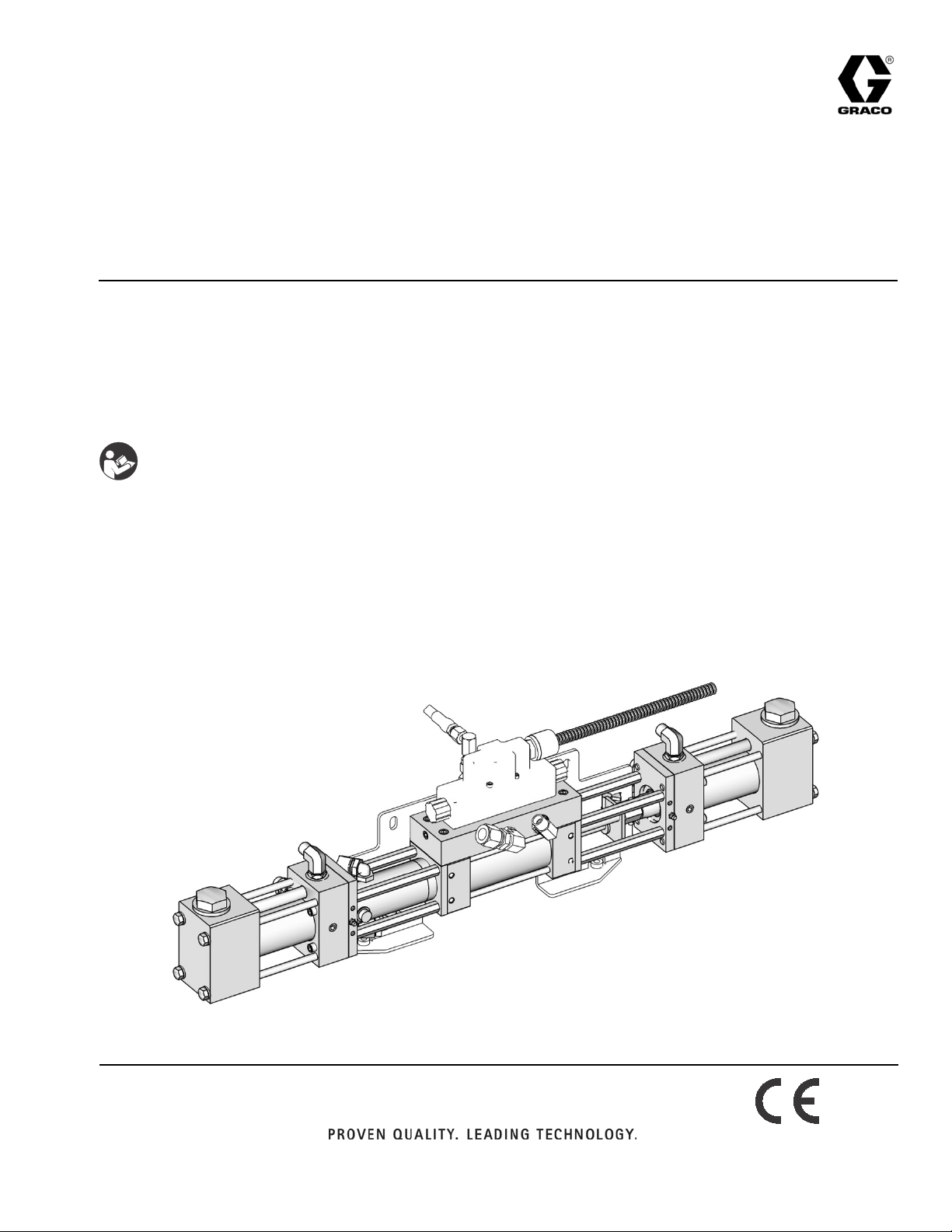
Proportioning Pumps
Proportioning pumps and hydraulic cylinders used on Hydraulic Proportioners. For
professional use only. For professional use only.
Not for use in explosive atmospheres.
Important Safety Instructions
Read all warnings and instructions in this manual
and all supplied manuals. Save all instructions.
Model 247576: 2000 psi (13.8 MPa, 138 bar) Maximum Working Pressure
EN
All other models: 3500 psi (24.0 MPa, 240 bar) Maximum Working Pressure
See page 2 for model information.
TI9778c
Page 2
Models
Contents
Models . . . . . . . . . . . . . . . . . . . . . . . . . . . . . . . . . . . 2
Proportioning Pumps . . . . . . . . . . . . . . . . . . . . . 2
Hydraulic Cylinders . . . . . . . . . . . . . . . . . . . . . . . 2
Pumplines . . . . . . . . . . . . . . . . . . . . . . . . . . . . . 2
In-Plant Pumpline . . . . . . . . . . . . . . . . . . . . . . . . 2
Repair . . . . . . . . . . . . . . . . . . . . . . . . . . . . . . . . . . . . 3
Flushing . . . . . . . . . . . . . . . . . . . . . . . . . . . . . . . 3
Pressure Relief Procedure . . . . . . . . . . . . . . . . . 3
Preventive Maintenance . . . . . . . . . . . . . . . . . . . 3
Pumpline Disassembly . . . . . . . . . . . . . . . . . . . . 4
Pumpline Reassembly . . . . . . . . . . . . . . . . . . . . 4
Pump Base Disassembly . . . . . . . . . . . . . . . . . . 6
Pump Base Reassembly . . . . . . . . . . . . . . . . . . . 6
Piston and Cylinder Seals . . . . . . . . . . . . . . . . . . 7
Hydraulic Cylinder . . . . . . . . . . . . . . . . . . . . . . . 9
Parts . . . . . . . . . . . . . . . . . . . . . . . . . . . . . . . . . . . . 15
Pumpline . . . . . . . . . . . . . . . . . . . . . . . . . . . . . . 15
Piston and Cylinder Seals . . . . . . . . . . . . . . . . . 16
Hydraulic Cylinder . . . . . . . . . . . . . . . . . . . . . . . 18
Technical Data . . . . . . . . . . . . . . . . . . . . . . . . . . . . 21
Graco Standard Warranty . . . . . . . . . . . . . . . . . . . 22
Graco Information . . . . . . . . . . . . . . . . . . . . . . . . 22
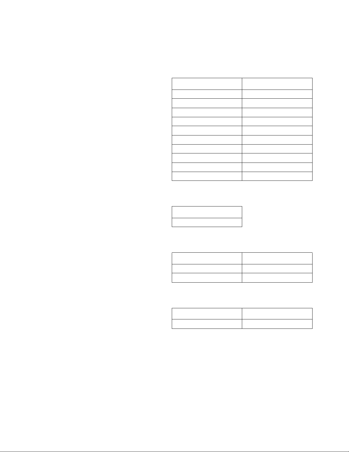
Models
Proportioning Pumps
Part, Series Cylinder Size
24F291, A #28
247371, A #30
247372, A #40
247373, A #48
247374, A #60
247375, A #80
247577, A #88
247376, A #96
247377, A #120
247576, A #140
Hydraulic Cylinders
Part, Series
295027
Pumplines
Part, Series Cylinder Size
288638 #80
288639 #120
In-Plant Pumpline
Part, Series Cylinder Size
P7758-255773 #80
2 312068M
Page 3
Repair
Repair
Flushing
Flush equipment only in a well-ventilated area. Do not
spray flammable fluids. Do not turn on heaters while
flushing with flammable solvents.
• Flush out old fluid with new fluid, or flush out old
fluid with a compatible solvent before introducing
new fluid.
• Use lowest possible pressure when flushing.
• To flush entire system, circulate through gun fluid
manifold (with manifold removed from gun).
• Always leave some type of fluid in system. Do not
use water.
Pressure Relief Procedure
Trapped air can cause the pump to cycle unexpectedly,
which could result in serious injury from splashing or
moving parts.
1. Select Park on Pump Control Switch if available, or
turn off.
2. Turn off feed pumps.
3. Trigger gun to relieve pressure.
4. Close gun inlet valves.
5. Close fluid supply inlet valves.
6. Service spray gun. See corresponding spray gun
manual.
Preventive Maintenance
When pumps are functioning properly, it is not unusual
for a trace amount of resin to seep past the pump packing onto the resin pump shaft. Routinely inspect shaft
and wipe away any residue when the proportioner is
turned off. Disassemble and clean the proportioning
pumps annually. For pumpline P7758-255773, disassemble and clean the proportioning pumps every six
months. Inspect the pistons and cylinder for marks or
scratches, which may cause leakage and damage to
packings. Replace all packings, o-rings, and bushings
annually. For pumpline P7758-255773, replace these
items every six months.
312068M 3
Page 4
Repair
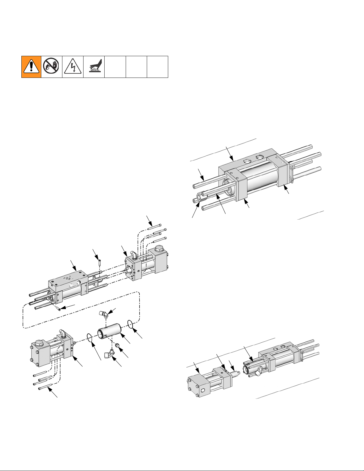
Pumpline Disassembly
1. Remove plug fitting (206) from lube cylinder (205).
2. Insert clevis pin removal tool 296607 through opening in lube cylinder (205) and screw tool into left
clevis pin (219). Pull clevis pin out of clevis (117).
3. Use hex key to remove four socket head cap
screws (203) from left proportioning pump (202).
Remove left proportioning pump.
4. Remove lube cylinder (205).
5. Screw pin removal tool 296607 into right clevis
pin (219). Pull clevis pin out of clevis (117).
6. Use hex key to remove four socket head cap
screws (203) on right proportioning pump (202).
Remove right proportioning pump.
203
Pumpline Reassembly
1. Slide the hydraulic piston (104) in the hydraulic
cylinder (201) out to its left-most position. The left
end of the left clevis (117) should be nearly in line
with the left end of the spacers (113). See the following image.
2. Place hydraulic cylinder (201) on flat surface with
both the manifold (125) and the port blocks (116)
contacting the surface. The two main ports in the
manifold should be facing up. See the following
image.
125
113
116
116
117
104
ti13871a
203
201
219
202
219
204
202
207
208
205
206
204
ti13870a
3. Install elbow fittings (207, 208) into lube
cylinder (206) and install lube cylinder over left
clevis (117). Ensure clevis pin hole in lube cylinder
is vertical, in line with the hole in the left clevis.
4. Place left proportioning pump (202) on flat surface
with the wide end of the outlet flange (26) facing
down.
5. Use clevis pin removal tool 296607 to slide the proportioning pump piston rod (28) out to its limit.
Ensure the hole in the proportioning pump shaft is
vertical, in line with the hole in the left clevis and
lube cylinder.
206
35
26
28
ti13875a
4 312068M
Page 5

Repair
6. Attach the clevis pin (219) to the clevis pin tool.
Insert clevis pin through hole in lube cylinder and
into the left clevis.
7. Gently tap end of clevis pin tool with hammer to
slide clevis pin (219) into place. Remove clevis pin
tool from clevis pin.
8. Insert four hex head cap screws (203) through holes
in proportioning pump (202) and partially screw into
spacers (113) in hydraulic cylinder (201).
9. With the four hex head cap screws in place but not
tightened, slide the proportioning pump against the
hydraulic cylinder.
10. Clamp the hydraulic cylinder and proportioning
pump assembly to the flat surface so the proportioning pump and hydraulic cylinder will not twist when
tightened against each other.
11. Tighten the hex head cap screws in a criss-cross
pattern.
12. Repeat steps 4-11 with the right proportioning
pump.
13. Install plug fitting (206) into lube cylinder (205).
14. Use grease pump to apply grease to grease
fittings (35) in proportioning pumps.
312068M 5
Page 6
Repair
Pump Base Disassembly
Disassemble and clean pump base annually. For
pumpline P7758-255773, disassemble and clean the
pump base on every six months.
1. Relieve pressure, page 3.
2. Turn OFF the main disconnect and lock out power at
the source.
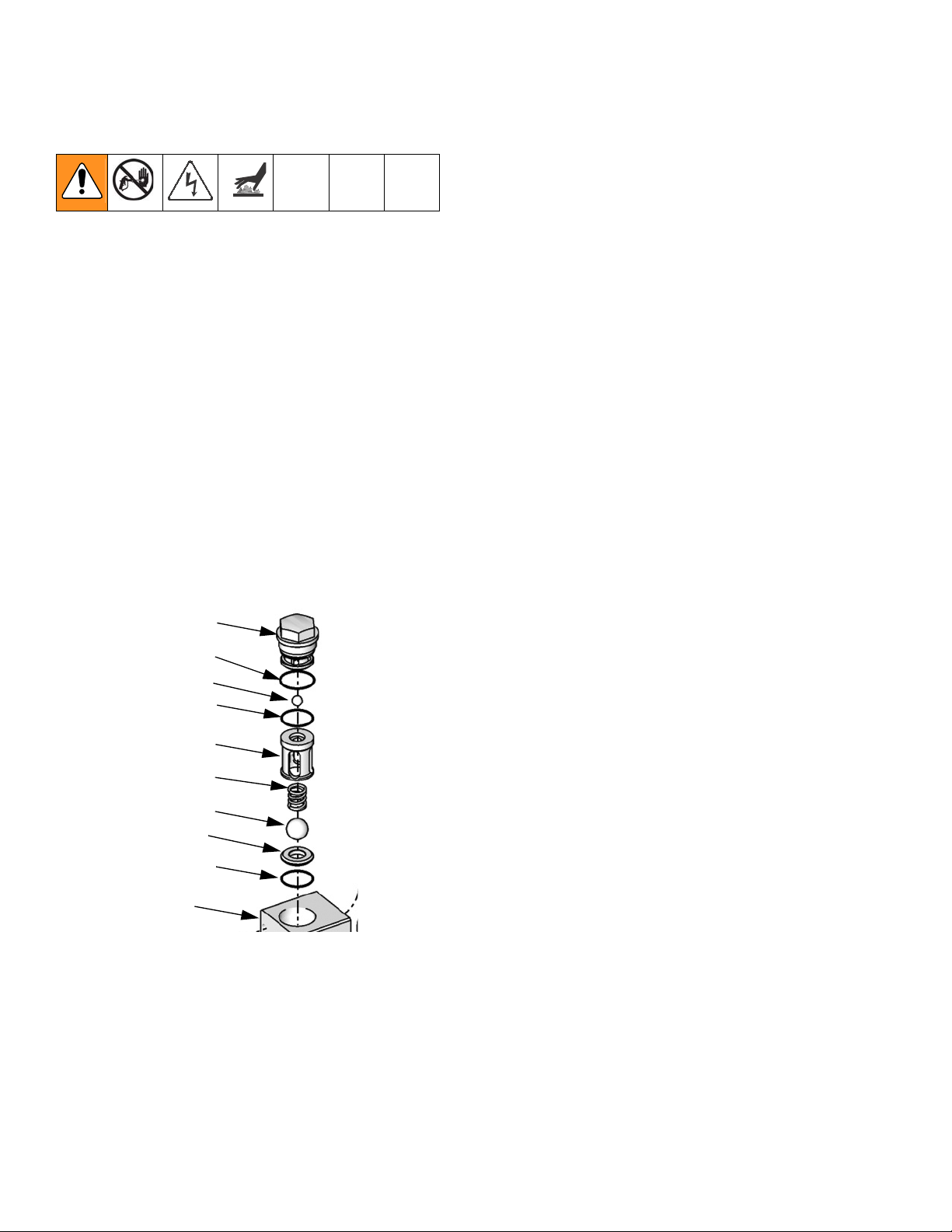
3. Remove pump cap (19) from pump base (23), and
remove o-ring (6):
a. Remove outlet ball (4) and o-ring (9).
b. Remove inlet ball cage (14), spring (22) and
inlet ball (10).
c. Remove inlet ball seat (11) and o-ring (9) from
bottom of cavity.
d. Thoroughly clean all metal parts in a compatible
solvent and inspect for wear or damage. Inspect
each ball and seat for nicks or scratches;
replace as required.
e. Replace all o-rings. Kit 261859 contains all
o-rings for pump base rebuild.
Pump Base Reassembly
1. Install inlet valve in pump base by inserting o-ring
(9), inlet ball seat (11), ball (10), spring (22), and
inlet ball cage (14) into pump base cavity. See Parts
on page 15.
2. Install outlet valve in pump base:
a. Install o-ring (9) and valve ball (4) into the cavity.
b. Install the o-ring (6) on pump cap (19). Install
and tighten cap to pump base. Torque to 75 ft-lb
(101.3 N•m).
TI9780b
19
6
4
9
14
22
10
11
9
23
6 312068M
Page 7
Repair
Piston and Cylinder Seals
Piston Seal and Cylinder Seal Repair Kits are available. See Table 1 on page 17 to order the correct
kits for your pump. Also see kit manual 312071.
Disassembly
1. Relieve pressure, page 3.
2. Turn OFF the main disconnect and lock out power at
the source.
3. Disconnect the pump inlet and outlet lines; see your
proportioner repair manual. Remove the four screws
(30) holding the pump outlet flange (26) to the
hydraulic cylinder. Disconnect pump from drive and
take pump assembly to a workbench.
4. Remove the four bolts (8) and washers (5). See
Parts on page 15.
5. Remove the flange retainer (27), gasket (17), bushing (13), and throat seal (29).
6. Use a soft-faced mallet to help separate pump base
(23) and outlet flange (26) from cylinder (12).
Remove crossover tube (24)
7. Remove piston from cylinder bore. Remove piston
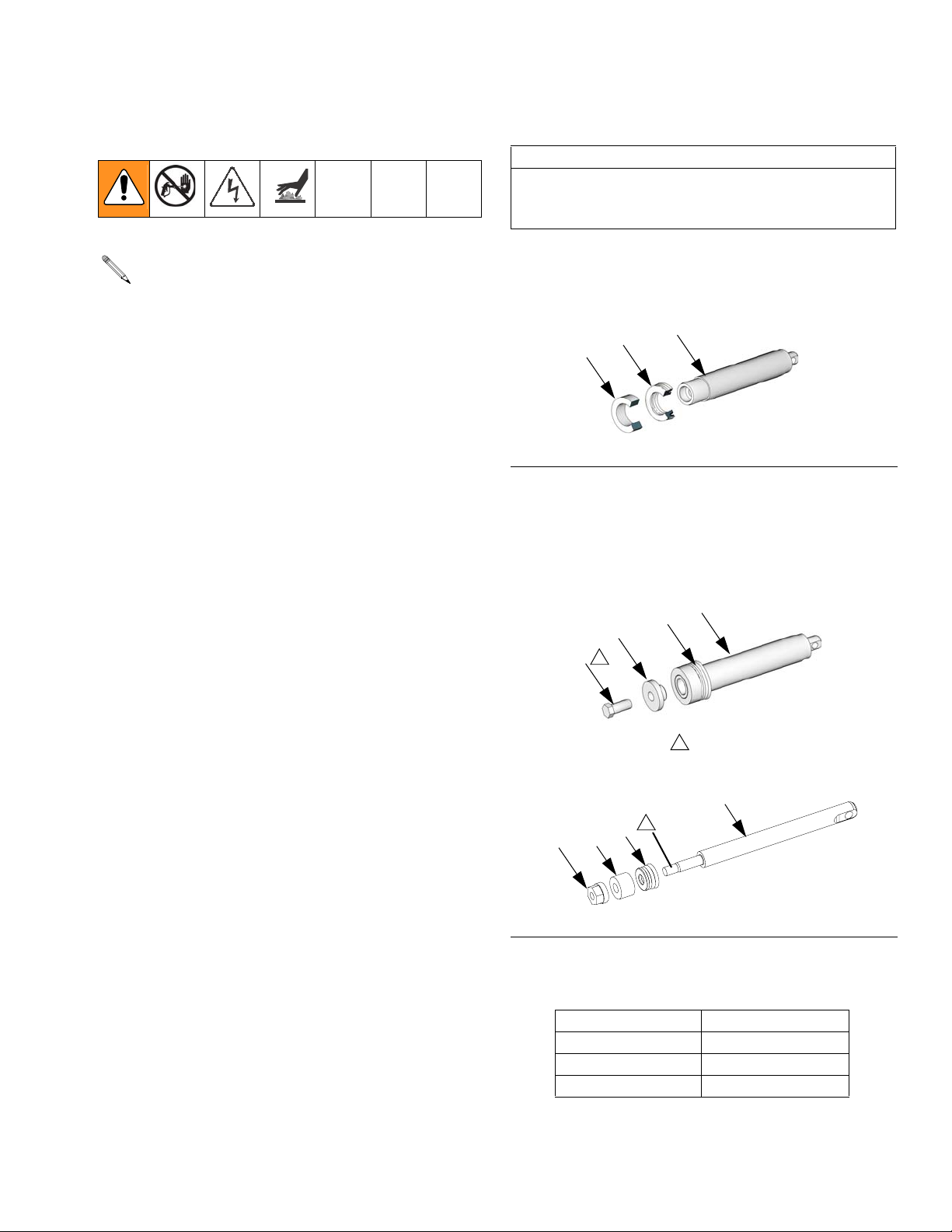
cap bolt (25), then slide bushing (18) and u-cup seal
(15) from rod.
Reassembly
CAUTION
To prevent cross-contamination of the equipment’s
wetted parts, never interchange component A (isocyanate) and component B (resin) parts.
1. Install piston rod seal (15); ensure u-cup faces piston rod (28) as shown in F
15
18
F
IG. 1: U-Cup Orientation
28
2. Assemble piston bolt (25) to piston rod (28). Apply
supplied thread sealant to piston bolt and tighten.
See Torque Specification table for torque according
to pump size.
15
3
25
1
#28 Pump Size
IG. 1.
TI9823a
28
1
Apply supplied sealant to threads.
28
TI9822a
8. Thoroughly clean all parts in a compatible solvent
and inspect for wear or damage. Replace as
25
18
15
1
required.
r_24f290_312068
IG. 2: Piston Head and Rod
F
Torque Specification
Pump Size Torque
30 130 in-lb (14.7 N•m)
28, 40, 48, 60 22 ft-lb (29.7 N•m)
80, 88, 96, 120, 140 45 ft-lb (60.8 N•m)
312068M 7
Page 8
Repair
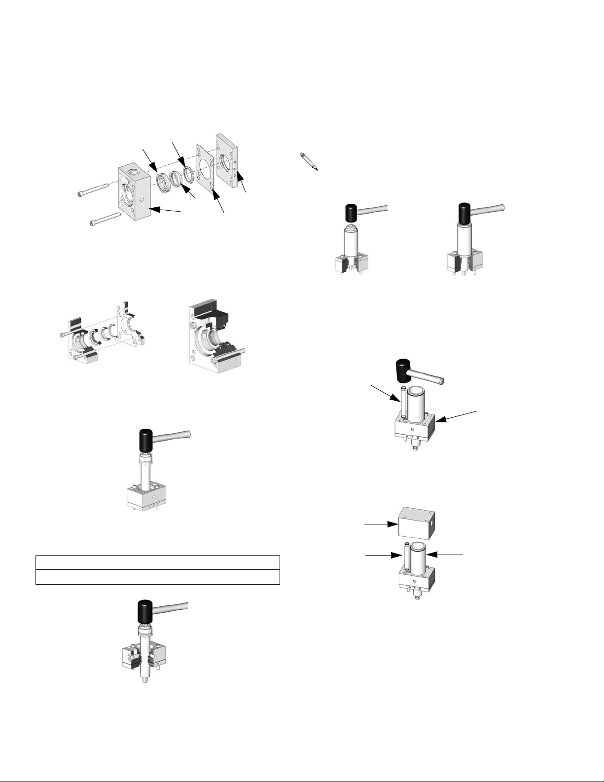
3. Using supplied bolts in the cylinder seal kits, press
seal (16) into outlet flange (26). Ensure seal faces
cylinder. Assemble bushing (13) throat seal (29) and
gasket (17) into flange retainer (27) and fasten to
outlet flange.
16
29
26
13
17
27
TI9782a
4. Ensure plate is parallel with block. Carefully tighten
screws until plate is flush with block. Be sure to
press seal straight into bore.
Seal Alignment
Pressed Seal
7. Lubricate and assemble o-rings (1) to cylinder (12).
8. Tap cylinder (12) onto piston rod (28) as shown in
the following figure. Be careful to not score piston
seal. Continue tapping cylinder until it seats in bore
of outlet flange (26).
Use grease to aid in insertion of cylinder onto piston rod.
TI9819a
TI9820a
Cylinder Assembly Seat Cylinder in Bore
9. Lubricate and assemble o-rings (2) to crossover
tube (24). Insert crossover tube into outlet flange
(26). Softly tap crossover tube into bore until it
seats.
TI9783b
TI9784b
5. Insert piston rod (28) through throat seal (29) on
front of block. Use grease to aid with insertion if
needed.
TI9787a
6. Place assembly in a vise, and tap piston rod (28)
through throat seal (29) and bearing.
CAUTION
Keep rod straight to prevent damage to throat seal.
24
26
TI9789a
10. Carefully align cylinder (12) and crossover tube (24)
to bores in pump base (23). Tap pump base until the
cylinder is fully seated in bore.
23
24
12
TI9790a
11. Install four bolts (8) and washers (5). Torque to 45
ft-lb (60.8 N•m).
TI9788a
8 312068M
Page 9
Repair
Hydraulic Cylinder
For repairs, order Hydraulic Cylinder Repair
Kit 296785.
Disassembly
Tools Required
• Two - 1 in. open-end wrench
• Two - 1/2 in. open-end wrench
• O-ring pick
1. Relieve pressure, page 3.
2. Turn OFF the main disconnect and lock out power at
the source.
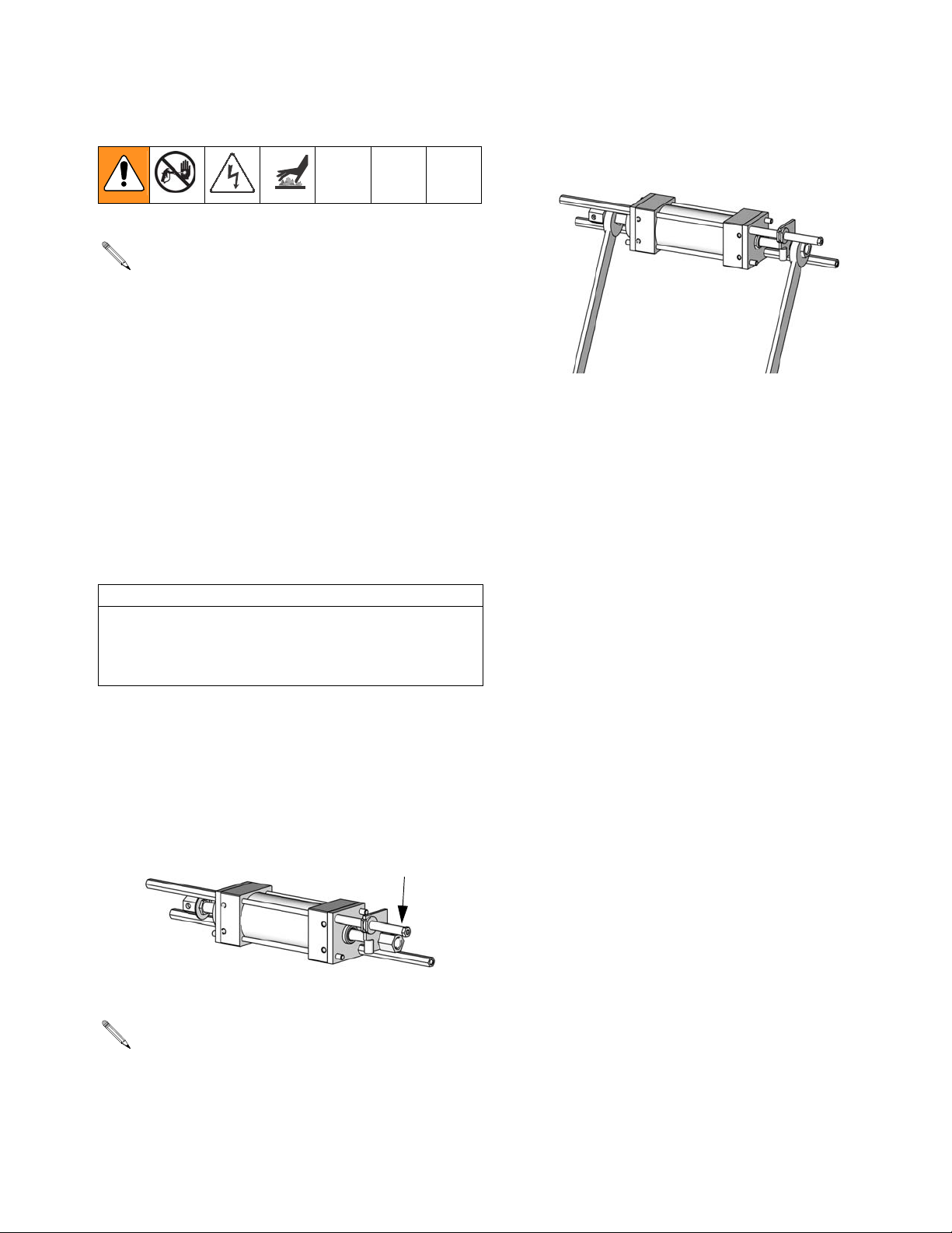
5. Using the 1 in. open-end wrench and the 1 in.
impact wrench, rotate the baffle jam nut away from
the right clevis until one of them breaks loose.
TI11285a1
If the left clevis and baffle jam nut break loose from
the hydraulic piston shaft:
6. Remove the clevis and baffle jam nut.
7. Remove the lubricator adapter (120).
8. Loosen and remove the remaining hex
spacers (113) and smooth spacer (114), keeping
the tie rods in place.
CAUTION
In the following step, attach the clamps to the port
blocks of the assembly. Attaching clamps to any other
part of the assembly may result in significant damage
when breaking loose the baffle jam nut and clevis.
3. Clamp the hydraulic cylinder to a flat surface using
c-clamps or another strong clamping device, ensuring that the cylindrical spacer (114) is to the right.
4. Using the 1/2 in. open-end wrenches, loosen and
remove four hexagonal spacers (113) to create
room to rotate the clevises.
114
TI11289a1
The clevises and the baffle jam nut were installed
with high strength thread sealant. The following
steps will require significant force to break loose the
baffle jam nut and clevises.
9. Remove the left retainer plate (101).
10. Remove the tie rods (115).
11. Remove the left port block and rod bushing assembly.
12. Slide the piston and everything attached to it out the
right side of the cylinder by holding the assembly by
the cylinder and pushing the left end of the piston
shaft against a flat surface.
13. Using a c-clamp, secure the port block (116) of the
remaining assembly.
14. Keeping the piston shaft from rotating using a 1/2 in.
wrench on the piston shaft flats and using a 1 in.
impact wrench on the right clevis, break loose and
remove the right clevis.
15. Remove the activator plate (119) and modified
bushing (118).
16. Remove the retainer plate (101).
312068M 9
Page 10
Repair
17. Remove the right port block and rod bushing
assembly.
18. Remove the rod bushings (103) from the port
blocks (116).
19. Using the o-ring pick, remove all rings and seals.
If the right clevis breaks loose from the hydraulic
piston shaft:
6. Remove the right clevis.
7. Remove the activator plate (119) and modified
bushing (118).
8. Remove the right retainer plate (101).
9. Remove the tie rods (115).
10. Remove the right rod bushing and port block
assembly.
11. Slide the piston and everything attached to it out the
left side of the cylinder by holding the assembly by
the cylinder and pushing the right end of the piston
shaft against a flat surface.
Reassembly
Tools Required
• Torque wrench set to 15 ft-lb (20 N•m) with
1 in. open-end attachment and
1/2 in. socket attachment
• 1 in. open-end wrench
• 1/2 in. open-end wrench
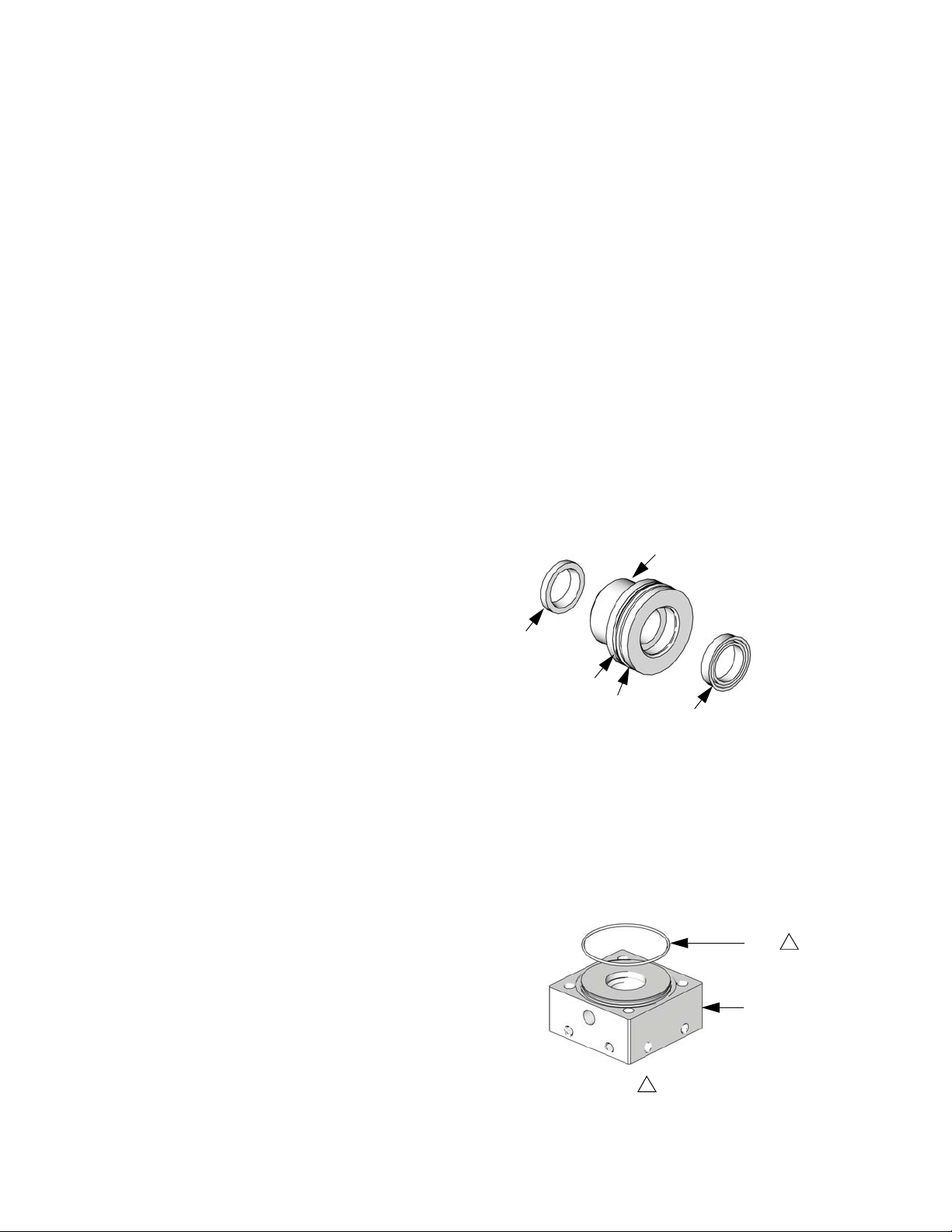
Assemble Rod Bushing to Port Block
1. Insert black o-ring (109) into the outside groove of
rod bushing (103).
2. With the wide end of the rod bushing facing down,
insert white back-up ring (110) above o-ring (109) in
the same groove.
3. With the lip facing out, push one rod wiper (111) into
the small end and one shaft seal (112) into the big
end of the rod bushing.
103
12. Using a c-clamp, secure the port block (116) of the
remaining assembly.
13. Break the baffle jam nut (122) loose from the
hydraulic piston shaft.
14. Keeping the piston shaft from rotating using a 1/2 in.
wrench on the piston shaft flats and using a 1 in.
impact wrench on the left clevis, break loose and
remove the left clevis.
15. Remove the left retainer plate (101).
16. Remove the left port block and rod bushing assembly.
17. Remove the rod bushings (103) from the port
block (116).
18. Using the o-ring pick, remove all rings and seals.
111
110
TI11275a
109
112
4. Place port block (116) on a flat surface with the
large opening facing up.
5. Using your hands, push the wide end of the rod
bushing into port block (116).
6. On the side opposite the rod bushing, place
o-ring (105) around the extruding circle.
105
1
116
TI11276a
1
Apply lithium
10 312068M
Page 11
Repair
7. Repeat the steps above to assemble the second rod
bushing/port block assembly.
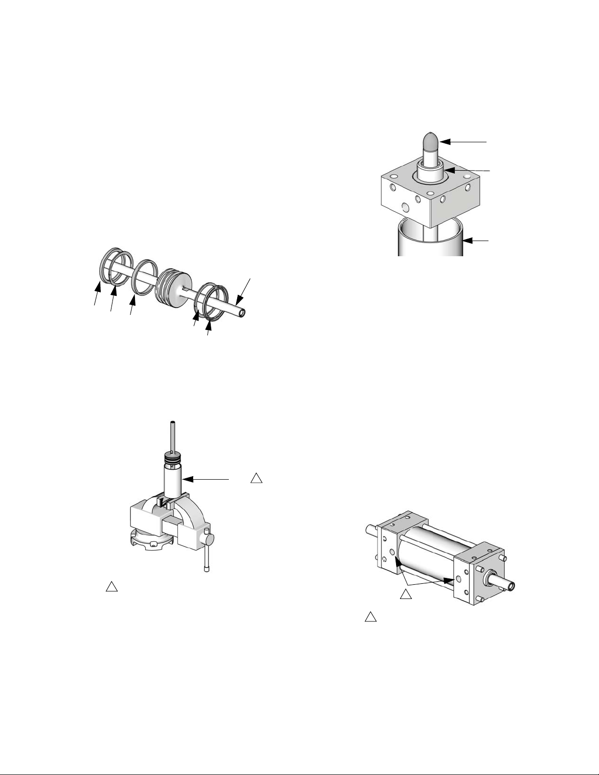
Assemble Hydraulic Piston and Insert in Cylinder
8. Place wear ring (108) in the center channel of
hydraulic piston (104).
9. With the lip facing away from the center channel,
place one u-cup seal (106) in each of the remaining
two channels of the hydraulic piston.
10. Place one back-up ring (107) in the same channel
as each of the u-cup seals on the side facing the
center channel.
104
106
107
108
TI11277a
107
106
Insert Piston into Cylinder
11. Slide the hydraulic piston into the cylinder (102). If
necessary, rest the cylinder on a vise or similar surface while pushing the piston into it.
Assembling Items onto Piston Shaft
12. With the rod bushing (103) facing away from the cylinder (102), slide the port block and rod bushing
assembly over the rod tool and onto the shaft.
A
103
102
TI11280a
13. Repeat with the other port block on the opposite end
of the hydraulic piston shaft.
Attaching Retainer Plates and First Four Spacers
14. Place the assembly on a flat surface with the port
hole on the two port blocks facing the same direction.
15. Slide one retainer plate over the end of each port
block.
16. Insert one tie rod into each of the four holes in the
port blocks and retainer plates. Keep an equal
amount of threads showing through the retainer
plate on each side.
1
102
facing in towards your body and place the assembly
on a flat surface.
TI11279a
1
17. Rotate the assembly so that the port holes are now
Apply lithium grease to the inside of
each end of the cylinder.
1
312068M 11
1
Make sure the port
holes are facing in towards your
TI11281a
Page 12
Repair
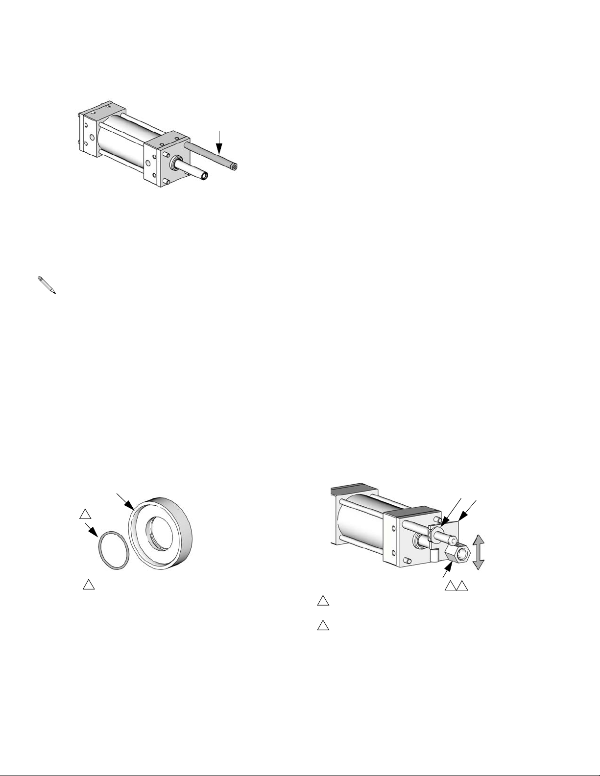
18. Using the far, top tie-rod, attach cylindrical
spacer (114) to the right side of the assembly.
114
TI11282a
19. Attach one hexagonal spacer (113) to the other end
of the tie rod. Do not tighten.
20. Attach one hexagonal spacer to each end of the bottom, near tie-rod. Do not tighten.
In the following step, the port holes need to be facing down, with the cylindrical spacer (114) facing
right.
21. Secure the assembly to a flat surface using two
c-clamps, or other strong clamping devices, to prevent the assembly from twisting. The assembly will
remain secured to the flat surface for the remainder
of the assembly procedure.
22. With the assembly secured, torque the spacers
against each other to 15 ft-lb (20 N•m).
Installing Lube Adapter
23. Push o-ring (121) into the inside groove of the cylinder lube adapter (120).
24. With the lip of the adapter facing left, slide the
adapter onto the left end of the hydraulic piston
shaft.
Installing Hex Clevises and Baffle Jam Nut
25. With the hex-side of the baffle jam nut facing away
from the hex-head of the clevis, spin the baffle jam
nut (122) onto the hex clevis (117). Leave one to
two threads between the head of the clevis and the
nut.
26. Apply high strength thread sealant (124) to the
threads of both hex clevises (117).
27. Apply primer (123) to the threads with the thread
sealant.
28. Attach modified bushing (118) to the activator
plate (119).
29. Insert the clevis (117) without the baffle jam
nut (122) into the corner hole of the activator
plate (119).
30. Slide the modified bushing over the cylindrical
spacer (114) and screw the clevis (117) into the
right end of the hydraulic piston shaft (104).
31. Spin the clevis (117) and baffle jam nut (122) onto
the left end of the hydraulic piston shaft finger-tight,
ensuring a gap of one to two threads between the
baffle jam nut and the head of the left clevis.
32. Rotate the right clevis until the cross-holes form a
vertical line.
120
121
1
TI11283a
1
Apply lithium grease to the o-ring.
1
Apply high strength thread sealant to threads of both
hex clevises.
2
Apply primer to the threads with the thread sealant to
speed curing.
12 312068M
117
118
1
119
TI11284a
2
Page 13
Repair
CAUTION
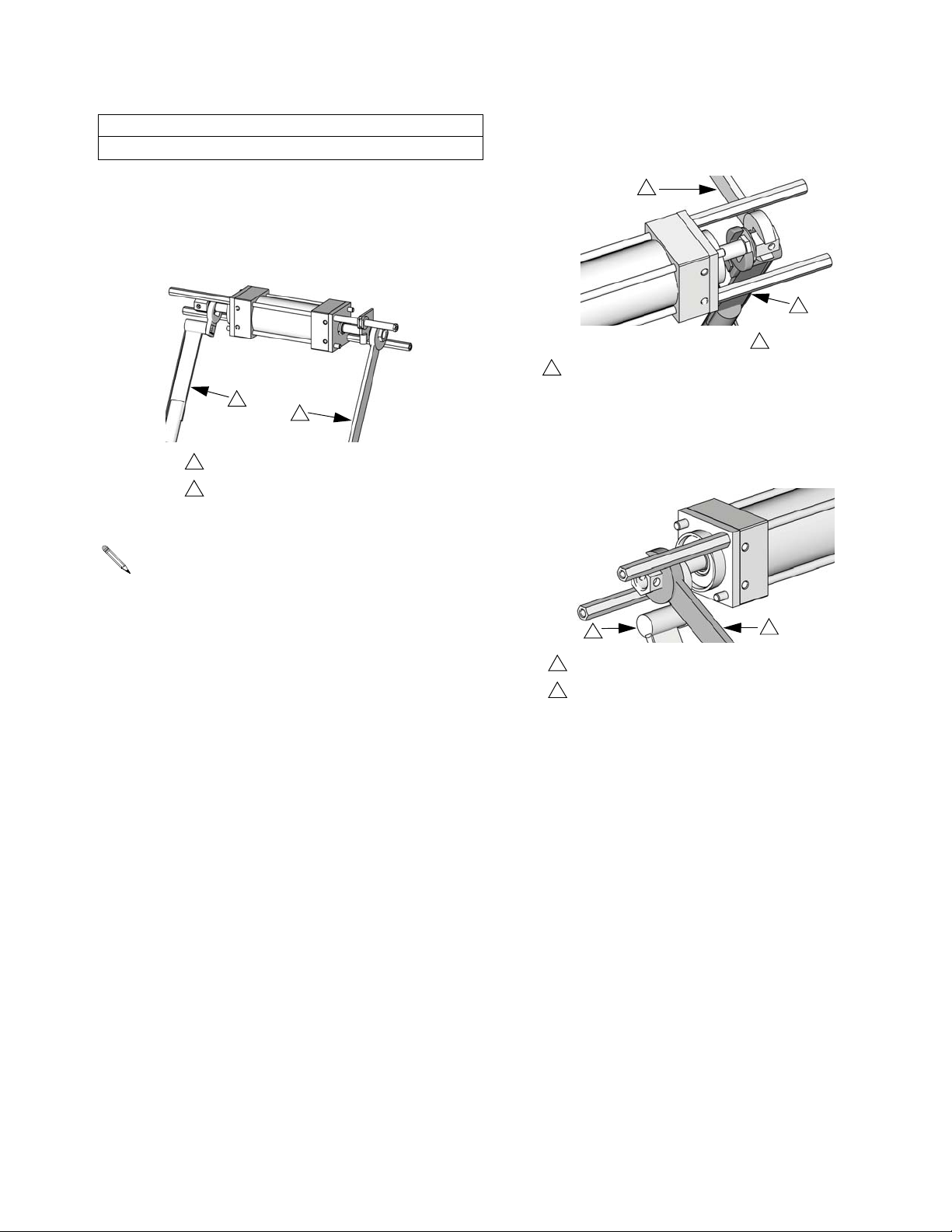
In the following step, do not over torque.
33. Hold the right clevis stationary with a 1 in. open-end
wrench and, by turning the baffle jam nut with a 1 in.
torque-wrench, torque the right clevis to 15 ft-lb
(20 N•m) against the activator plate.
2
1
Hold stationary.
2
Rotate to torque the right clevis.
1
TI11285a
In the following step, do not unscrew the left clevis
more than necessary.
34. Hold the left clevis stationary with a 1 in. wrench and
break the baffle jam nut loose from the hydraulic piston shaft.
1
2
TI11286a
1
Hold stationary.
2
Rotate to break baffle jam nut loose from piston shaft.
35. Hold the baffle jam nut stationary and rotate the left
clevis so the cross-holes form a horizontal line,
keeping one to two threads between the clevis head
and the nut.
1
1
Hold baffle jam nut stationary.
2
Rotate to position cross-holes in a horizontal line.
2
TI11287a
312068M 13
Page 14
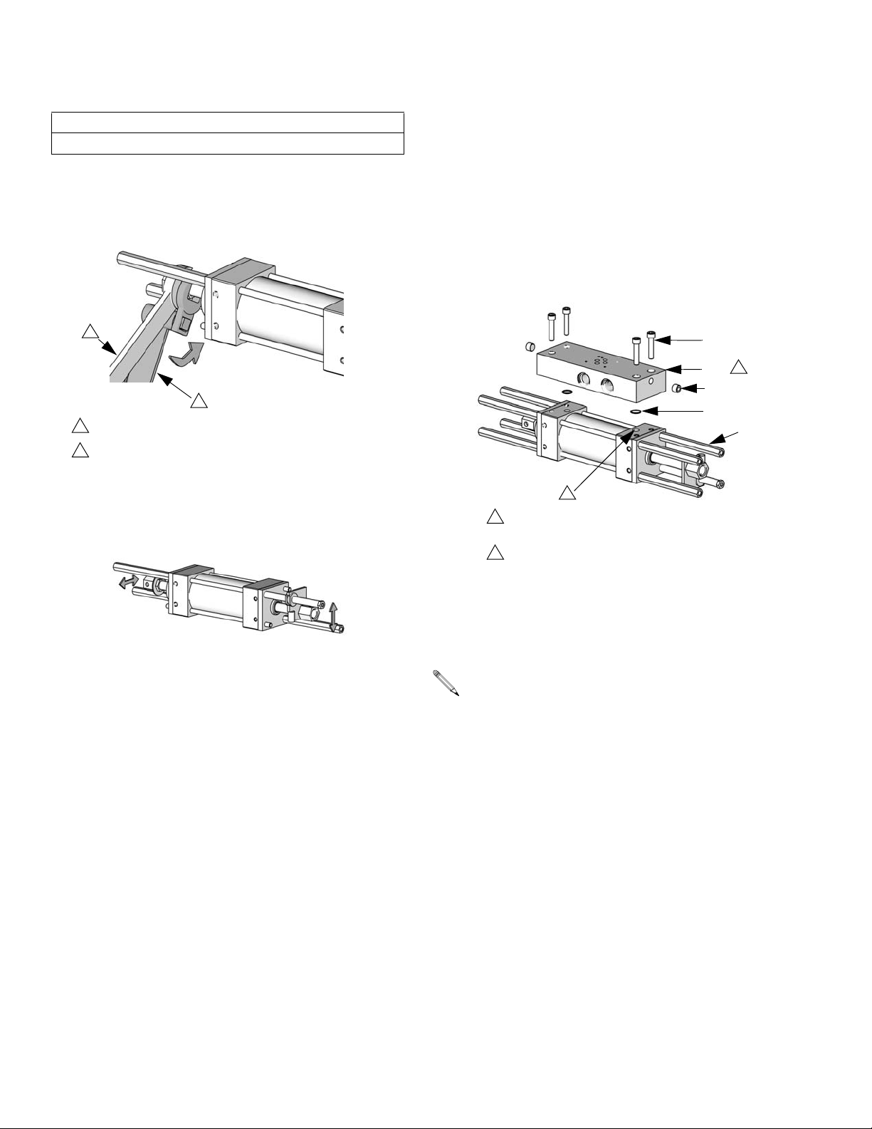
Repair
CAUTION
In the following step, do not over torque.
36. Hold the left clevis stationary with a 1 in. open-end
wrench to keep the cross-holes horizontal and
torque the baffle jam nut against the hydraulic piston
shaft to 15 ft-lb (20 N•m) using a torque wrench.
butts against the retainer plate (101). Repeat for
opposite end of tie rod.
Assembling Manifold
39. Insert pipe plugs (127) into manifold (125).
40. Insert o-rings (128) into bottom holes of manifold.
41. With the port holes facing the manifold, attach the
manifold to the port blocks using the four
screws (126).
1
TI11288a
2
1
Hold stationary.
2
Rotate to torque the baffle jam nut to 15 ft-lb (20 N•m)
against the hydraulic piston shaft, which torques the left
clevis.
37. Double check that the left clevis cross-holes are horizontal and the right clevis cross-holes are vertical.
TI11289a
Installing Final Four Spacers
38. Preventing the tie rod (115) from spinning with one
hand, spin one spacer (113) onto one end until it
126
2
125
127
128
113
1
1
Have the port holes facing the
manifold.
2
On Model 247624, rotate manifold 180
degrees about the vertical axis.
TI11291a
42. Hold one spacer with the 1/2 in. open-end wrench
and the other with the 1/2 in. torque wrench and
torque to 15 ft-lb (20 N•m).
This ensures that the manifold is aligned with the
pump assembly.
43. Repeat with the final two spacers.
14 312068M
Page 15
Parts
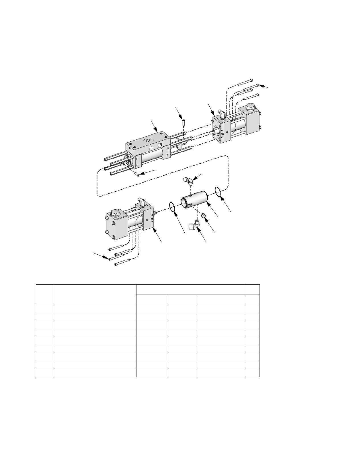
Pumpline
Parts
203
203
201
219
202
219
204
202
207
208
205
206
204
ti13870a
Pumpline Assembly
Ref Description
201 CYLINDER, hydraulic 295027 295027 247624 1
202 PUMP, proportioner 247375 247377 247375 2
203 SCREW, cap, socket head 295824 295824 0204-5 8
204 PACKING, o-ring 106258 106258 106258 2
205 CYLINDER, lube 261863 261863 261863 1
206 FITTING, plug 295829 295829 295829 1
207 FITTING, elbow, 90 degree 295826 295826 295826 1
208 FITTING, elbow, 90 degree 295397 295397 295397 1
219 PIN, clevis 296653 296653 296653 2
312068M 15
288638 288639 P7758-255773 Qty
Page 16
Parts
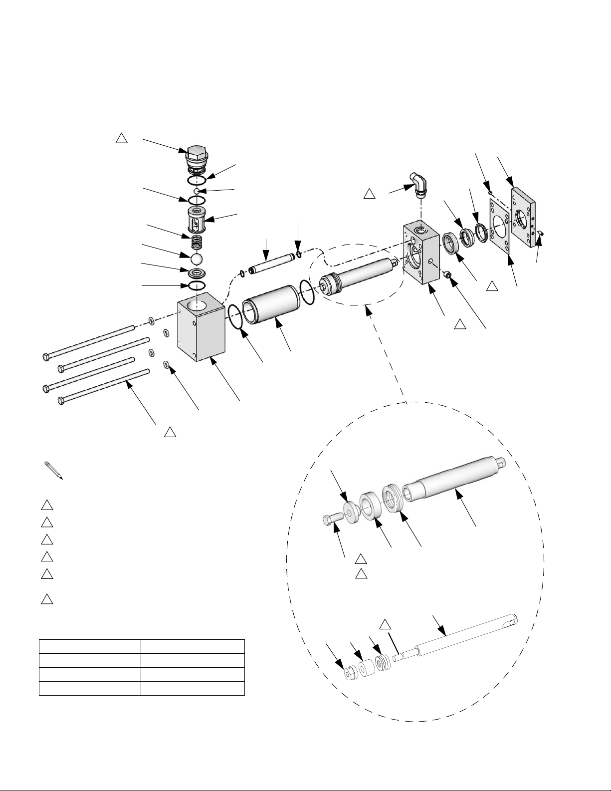
Piston and Cylinder Seals
A Side Shown
19
2
36
27
6
49
14
22
24
10
11
9
1
23
5
8
3
B side of pump is same as A side except items 31,
34, 35, and 36 are reversed.
12
29
34
6
13
2
35
16
4
17
26
4
31
TI9780b
Piston Assembly
3
1
Apply supplied sealant to threads
2
Torque to 75 ft-lb (101.3 N•m)
3
Torque to 45 ft-lb (60.8 N•m)
4
Seal must be pressed straight into housing
5
See Torque Specification table for torque
according to pump size
6
Part not used on Model P7758-255773
18
25
1
5
#28 Piston Assembly
28
15
TI9778a
28
Item 25 Torque Specification
25
18
15
1
Pump Size Torque
30 130 in-lb (14.7 N•m)
28, 40, 48, 60 22 ft-lb (29.7 N•m)
r_24f290_312068
80, 88, 96, 120, 140 45 ft-lb (60.8 N•m)
16 312068M
Page 17
Parts
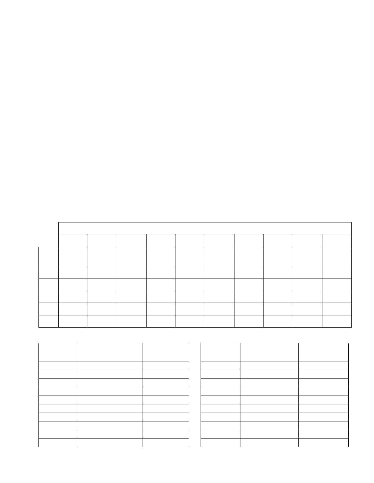
Ref. Part Description Qty
1 O-RING, PTFE 2
2 O-RING, TPE 2
3 CAP, piston 1
4 105445 BALL, valve, outlet, SST; 1/2 in. (13
mm) diameter
5 261866 WASHER, flat, packing support
(4 pack)
6 O-RING, PTFE 1
8 261865 SCREW, hex hd cap; 3/8-24 x 9.0
in. (228 mm) (4 pack)
9 O-RING, PTFE 2
10 107167 BALL, valve, inlet, SST; 1 in. (25
mm) diameter
11 193395 SEAT, ball, inlet, carbide 1
12 CYLINDER 1
13 BUSHING, throat, acetal 1
14 261899 GUIDE, inlet ball, with outlet ball
seat
15 SEAL, piston, u-cup 1
Refer to Table 1 for part number.
Refer to Table 2 for part number.
Table 1. Proportioning Pump Parts
16 SEAL, throat, u-cup 1
17 GASKET 1
18 BUSHING, piston, acetal 1
19 261867 CAP, ball guide 1
22 261897 SPRING, valve 1
1
23 261903 PUMP, base 1
24 261898 TUBE, crossover 1
1
25 SCREW, hex hd cap 1
26 FLANGE, outlet 1
27 261875 RETAINER, flange 1
1
28 ROD, piston; includes cap (ref. 3) 1
29 ADAPTER, throat 1
31 295225 PLUG, pipe, flush 1
1
34 121312 ELBOW, 3/4-16 unf x 1/2 in. (13
mm) O.D. tube (not used on Model
P7758-255773)
35 295229 FITTING, grease; 1/4-28 1
36 M70430 SCREW, set; 1/4-28 x 3/16 in. 1
1
Refer to Table 3 for part number.
Parts included in Kit 261859 (purchase separately).
1
Pump Sizes and Part Numbers
#28 #30 #40 #48 #60 #80 #88 #96 #120 #140
Part
Ref. 24F291 247371 247372 247373 247374 247375 247577 247376 247377 247576
16F204 261889 261886 261886 261886 261883 261883 261883 261883 261883
3
24F294 261896 261895 261894 261893 261892 247582 261891 261890 247583
12
261902 261902 261902 261902 261902 261901 261901 261901 261901 261901
26
16F202 261882 261881 261880 261879 261878 247584 261877 261876 247585
28
261874 261874 261873 261872 261871 261870 247586 261869 261868 247587
29
Table 2. Cylinder Seal Kits; Includes Parts 13, 16, 17
Proportioning Pump
Pump
24F291 28 261858
247371 30 261858
247372 40 261857
247373 48 261856
247374 60 261855
247375 80 261854
247577 88 247580
247376 96 261853
247377 120 261852
247576 140 247581
Size Kit
Table 3. Piston Seal Kits; Includes Parts 15, 18, 25
Proportioning
Pump
24F291 28 24F292
247371 30 261851
247372 40 261850
247373 48 261849
247374 60 261848
247375 80 261847
247577 88 247578
247376 96 261846
247377 120 261845
247576 140 247579
Pump Size Kit
312068M 17
Page 18
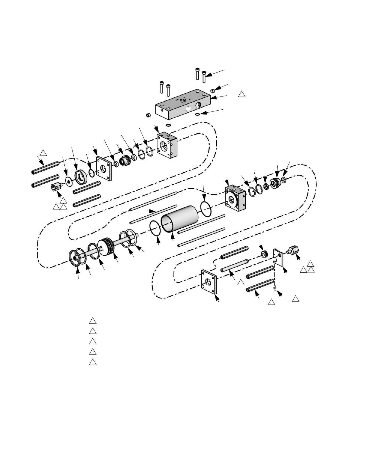
Parts
Hydraulic Cylinder
111
101
121
113
120
122
3
112
103
110
109
116
105
116
126
127
125
128
109
4
111
103
112
110
117
2
1
3
115
105
102
118
106
106
107
104
108
107
101
1
Apply high strength thread sealant to threads.
2
Apply primer to threads to speed curing.
3
Torque to 15 ft-lb (20 N•m). See assembly section for correct procedure.
4
On Model 247624, rotate manifold 180 degrees about the vertical axis.
5
Part used only on Model P7758-255773.
114
3
3
113
119
129
117
5
1
3
2
TI11292a
18 312068M
Page 19

Parts
Ref. Part Description Qty.
101 295029 PLATE, retainer 2
102 295030 CYLINDER 1
103 295031 BUSHING, rod 2
104 296642 PISTON, hydraulic 1
105 295640 O-RING 2
106 295641 SEAL, u-cup 2
107 295642 RING, back-up 2
108 296643 RING, wear 1
109 158776 PACKING, o-ring 2
110 295644 RING, back-up 2
111 295645 WIPER, rod 2
112 296644 SEAL, shaft 2
113 295032 SPACER, proportioner pump 7
114 261502 SPACER, reverse switch pump 1
115 295034 ROD, tie 4
116 295035 BLOCK, port 2
117 261864 CLEVIS, hex, proportioner 2
118 261862
BUSHING, modified
(used on Models 247624,
255723., 295027)
1501-7-2
BUSHING
(used on Model P7758-255773)
119 261507
PLATE, activator
(used on Model 295027)
42430-4
PLATE, activator
(used on Model P7758-255773)
247607
PLATE, activator
(used on Model 255723)
120 261863 ADAPTER, lube, cylinder 1
Ref. Part Description Qty.
121 177156 O-RING 1
122 295852 NUT, jam, baffle 1
123 SOLVENT, catalyst, liquid 1
124 SEALANT, anaerobic 1
125 298040 MANIFOLD, hydraulic
1
(used only on Model 247624)
126 113467 SCREW, cap, socket head
4
(used only on Model 247624)
127 295225 PLUG, pipe, flush
2
(used only on Model 247624)
128 112793 O-RING
2
(used only on Model 247624)
129 OP307-2
-1000
PIN, link
(used only on Model
1
P7758-255773)
130 296653 PIN, clevis; not shown
2
(used only on Model 255723)
1
1
Parts are also included in Hydraulic Cylinder Repair
Kit 296785 which can be purchased separately.
1
1
1
312068M 19
Page 20

Parts
20 312068M
Page 21
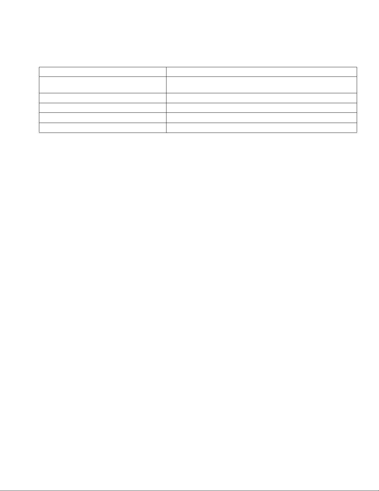
Technical Data
Category Data
Maximum working pressure
Maximum fluid temperature
Viscosity range
Maximum material inlet pressure
Wetted parts
Model 247576: 2000 psi (13.8 MPa, 138 bar)
All other models: 3500 psi (24.0 MPa, 240 bar)
120°F (49°C)
250-1500 centipoise
400 psi (2.7 MPa, 27 bar)
Carbon Steel, Stainless Steel, Chrome, PTFE, Acetal, UHMWPE
Technical Data
312068M 21
Page 22

Graco Standard Warranty
Graco warrants all equipment referenced in this document which is manufactured by Graco and bearing its name to be free from defects in
material and workmanship on the date of sale to the original purchaser for use. With the exception of any special, extended, or limited warranty
published by Graco, Graco will, for a period of twelve months from the date of sale, repair or replace any part of the equipment determined by
Graco to be defective. This warranty applies only when the equipment is installed, operated and maintained in accordance with Graco’s written
recommendations.
This warranty does not cover, and Graco shall not be liable for general wear and tear, or any malfunction, damage or wear caused by faulty
installation, misapplication, abrasion, corrosion, inadequate or improper maintenance, negligence, accident, tampering, or substitution of
non-Graco component parts. Nor shall Graco be liable for malfunction, damage or wear caused by the incompatibility of Graco equipment with
structures, accessories, equipment or materials not supplied by Graco, or the improper design, manufacture, installation, operation or
maintenance of structures, accessories, equipment or materials not supplied by Graco.
This warranty is conditioned upon the prepaid return of the equipment claimed to be defective to an authorized Graco distributor for verification of
the claimed defect. If the claimed defect is verified, Graco will repair or replace free of charge any defective parts. The equipment will be returned
to the original purchaser transportation prepaid. If inspection of the equipment does not disclose any defect in material or workmanship, repairs will
be made at a reasonable charge, which charges may include the costs of parts, labor, and transportation.
THIS WARRANTY IS EXCLUSIVE, AND IS IN LIEU OF ANY OTHER WARRANTIES, EXPRESS OR IMPLIED, INCLUDING BUT NOT LIMITED
TO WARRANTY OF MERCHANTABILITY OR WARRANTY OF FITNESS FOR A PARTICULAR PURPOSE.
Graco’s sole obligation and buyer’s sole remedy for any breach of warranty shall be as set forth above. The buyer agrees that no other remedy
(including, but not limited to, incidental or consequential damages for lost profits, lost sales, injury to person or property, or any other incidental or
consequential loss) shall be available. Any action for breach of warranty must be brought within two (2) years of the date of sale.
GRACO MAKES NO WARRANTY, AND DISCLAIMS ALL IMPLIED WARRANTIES OF MERCHANTABILITY AND FITNESS FOR A
PARTICULAR PURPOSE, IN CONNECTION WITH ACCESSORIES, EQUIPMENT, MATERIALS OR COMPONENTS SOLD BUT NOT
MANUFACTURED BY GRACO. These items sold, but not manufactured by Graco (such as electric motors, switches, hose, etc.), are subject to
the warranty, if any, of their manufacturer. Graco will provide purchaser with reasonable assistance in making any claim for breach of these
warranties.
In no event will Graco be liable for indirect, incidental, special or consequential damages resulting from Graco supplying equipment hereunder, or
the furnishing, performance, or use of any products or other goods sold hereto, whether due to a breach of contract, breach of warranty, the
negligence of Graco, or otherwise.
FOR GRACO CANADA CUSTOMERS
The Parties acknowledge that they have required that the present document, as well as all documents, notices and legal proceedings entered into,
given or instituted pursuant hereto or relating directly or indirectly hereto, be drawn up in English. Les parties reconnaissent avoir convenu que la
rédaction du présente document sera en Anglais, ainsi que tous documents, avis et procédures judiciaires exécutés, donnés ou intentés, à la suite
de ou en rapport, directement ou indirectement, avec les procédures concernées.
Graco Information
For the latest information about Graco products, visit www.graco.com.
TO PLACE AN ORDER, contact your Graco distributor or call to identify the nearest distributor.
Phone: 612-623-6921 or Toll Free: 1-800-328-0211 Fax: 612-378-3505
All written and visual data contained in this document reflects the latest product information available at the time of publication.
GRACO INC. AND SUBSIDIARIES • P.O. BOX 1441 • MINNEAPOLIS MN 55440-1441 • USA
Copyright 2007, Graco Inc. All Graco manufacturing locations are registered to ISO 9001.
Graco reserves the right to make changes at any time without notice.
For patent information, see www.graco.com/patents.
Orignal instructions. This manual contains English. MM 312068
Graco Headquarters: Minneapolis
International Offices: Belgium, China, Japan, Korea
www.graco.com
Revised April 2012
 Loading...