

Page 1
Instructions-Parts
Alternator
313293C
Conversion Kit
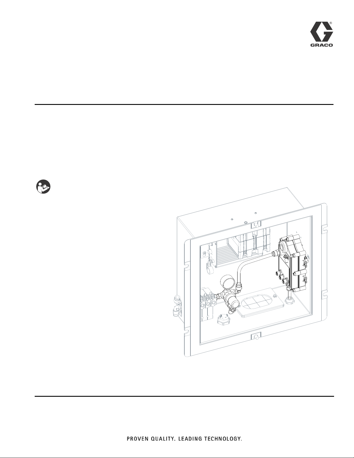
For converting an XM plural-component sprayer wall power supply to a turbine power
supply. For professional use only.
Not for use in explosive atmospheres.
Part No. 256991
Important Safety Instructions
Read all warnings and instructions in the XM
Plural-Component Sprayer Operation manual.
Save these instructions.
EN
For patent information, see www.graco.com/patents
r_256991_313293_13a
Page 2

Related Manuals
Contents
Related Manuals . . . . . . . . . . . . . . . . . . . . . . . . . . . 2
Component Identification . . . . . . . . . . . . . . . . . . . . 3
Installation . . . . . . . . . . . . . . . . . . . . . . . . . . . . . . . . 4
Remove Power Supply . . . . . . . . . . . . . . . . . . . . 4
Install Alternator . . . . . . . . . . . . . . . . . . . . . . . . . 5
Install Regulator Assembly . . . . . . . . . . . . . . . . . 5
Setup . . . . . . . . . . . . . . . . . . . . . . . . . . . . . . . . . . . . . 6
Connect Hose . . . . . . . . . . . . . . . . . . . . . . . . . . . 6
Connect Cables . . . . . . . . . . . . . . . . . . . . . . . . . . 6
Set Air Regulator . . . . . . . . . . . . . . . . . . . . . . . . . 6
Parts . . . . . . . . . . . . . . . . . . . . . . . . . . . . . . . . . . . . . 7
Technical Data . . . . . . . . . . . . . . . . . . . . . . . . . . . . . 8
Graco Standard Warranty . . . . . . . . . . . . . . . . . . . 10
Graco Information . . . . . . . . . . . . . . . . . . . . . . . . 10
Related Manuals
Component Manuals in U.S. English:
Manual Description
312359
313289
313292
XM Plural-Component Sprayer
Operation
XM Plural-Component Sprayer
Repair
XM Plural-Component Sprayer,
Instructions-Parts
2 313293C
Page 3
Component Identification
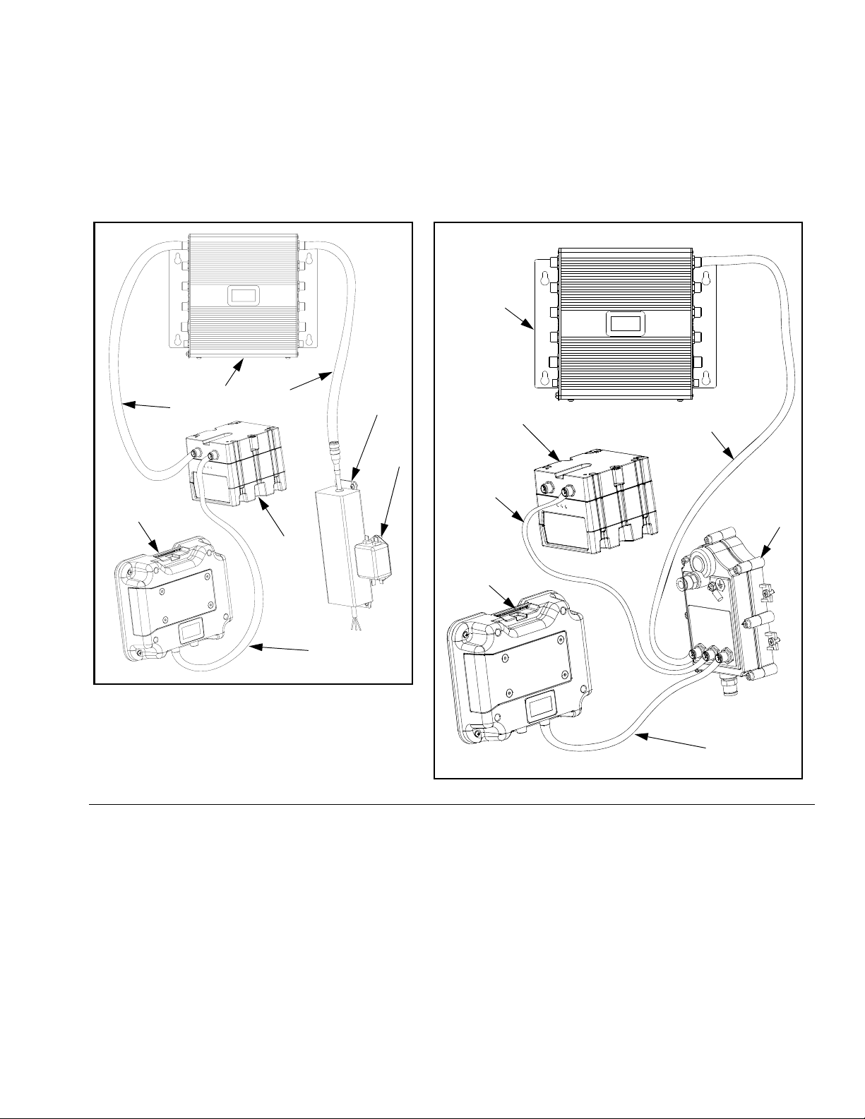
Component Identification
Power Supply Cable Connections
D
G
J
C
B
Alternator Conversion Kit Cable Connections
D
E
B
J
F
3
A
C
H
r_256991_313293_10
FIG. 1: Typical Installation
Key:
A Alternator
B USB Module
C Display Module
D Fluid Control Module
E Power Supply
F Filter Assembly
G Power Supply Cable
H CAN cable 15V779 (communication/power)
J CAN cable 15V778 (communication/power)
3 CAN cable 15V782 (USB power cable)
4 CAN cable 15V783 (Display power cable)
4
r_256991_313293_9
313293C 3
Page 4

Installation
Installation
6. Disconnect CAN cable (H) from USB front CAN connector and display module (C). See F
3.
IG. 1 on page
It is required to remove the power supply before installing the alternator conversion kit. Always have a qualified
electrician perform wiring connections.
Remove Power Supply
1. Shutdown XM plural-component sprayer. See operation manual 312359 for shutdown procedure.
2. Disconnect incoming power cable connections to
power supply (E) and ground lead (X) from junction
box (JB).
D
JB
G
NOTE:
Cable (H) will not be used for alternator conversion kit.
7. Disconnect CAN cable (J) from USB module and
fluid control module. Do not discard cable (J). CAN
cable (J) will be used by alternator conversion kit.
NOTE:
Keep power supply (E) and filter (F) connected so that
you can easily reinstall your power supply.
E
r_256991_313293_3
FIG. 2: Remove Power Supply
3. Disconnect power supply cable (G) from fluid control
module (D).
4. Disconnect power cable from power filter (F) and
from terminal blocks in junction box (not shown).
5. Loosen mounting screws and remove power supply
(E) and filter (F) from control box (CB).
4 313293C
X
F
Page 5

Installation
Install Alternator
1. Use screws (14) to install alternator (1) inside junction box (JB).
JB
1
14
F
IG. 3: Install Alternator
2. Install screw (14) through other end of grounding
wire (17), washer (19), and mounting hole beneath
the grounding label inside junction box (JB).
r_256991_313293_12a
Install Regulator Assembly
1. Position regulator (6) for proper air flow direction.
L
13
5
12
6
a
i
r
9
7
FIG. 5: Install Regulator Assembly
2. Connect pressure gauge (12), elbow (7), safety
valve (9), elbow fitting (10) and nipple fitting (5) to air
regulator (6). Use pipe sealant on all non-swiveling
and threads without gaskets.
3. Remove plug (K) from solenoid bank (L) and install
swivel (13).
4. Connect regulator assembly to swivel (13) and
tighten.
10
f
l
o
w
K
r_256991_313293_1
GS
JB
18
19
17
14
r_256991_313293_6a
IG. 4: Connect Grounding Wire
F
3. Connect terminal ring on GND wire (17) to GND
screw (GS) on alternator (1). Tighten with nut (18).
313293C 5
Page 6

Setup
Setup
Connect Hose
1. Connect tubing (15) between the air regulator outlet
fitting (10) and the alternator air inlet (M).
M
15
N
10
P
Connect Cables
Use reference labels located near CAN connectors to
properly connect components that are connected with
the alternator. Each CAN cable is marked with the part
number. The ends with the blue-colored sockets attach
to the alternator. See F
Conversion Kit Cable Connections.
1. Connect 15V782 CAN cable (3) to CAN connectors on USB module (B) and alternator (A).
2. Connect 15V778 CAN cable (J) to CAN
connectors on alternator (A) and fluid control module (D).
3. Connect 15V783 CAN cable (4) to CAN connectors on alternator (A) and display module (C).
IG. 1 on page 3 for Alternator
Set Air Regulator
Use the air regulator (6) to set the air pressure to 18 +/1 psi (124 kPa, 1.24 bar).
r_256991_313293_8
IG. 6: Hose Connections
F
2. Feed tubing (21) up through cord grip (P) and connect to alternator exhaust fitting (N).
3. Tie down exhaust tubing (15) to XM sprayer frame
with tie straps (22) where it exhausts downward with
no restrictions.
NOTICE
Ensure that the tubing (15) is clear of any moving
parts.
6 313293C
Page 7

Parts
256991, Alternator Conversion Kit
Parts
13
1
14
18
12
6
5
10
7
14
19
17
14
r_256991_313293_11
9
Ref. Part Description Qty.
1 255728 MODULE, alternator 1
3† 15V782 CABLE, I.S. CAN, male/ female, 20
in.
4† 15V783 CABLE, male A to female B code,
39 in.
5 156971 NIPPLE, short 1
6 115243 REGULATOR, air, 1/4 npt 1
7 112307 ELBOW, street 1
9 15W017 VALVE, safety, regulator 1
10 115841 ELBOW 1
12 104655 GAUGE 1
13 156823 UNION, swivel 1
14 110637 SCREW, panhead 5
15† C12508 TUBING, nylon, round; 9 in. 1
16† 121794 TAPE, PTFE; 260 in. roll 1
313293C 7
Ref. Part Description Qty.
17 194337 WIRE, ground 1
18 100284 NUT, hex 1
1
19 111307 WASHER, lock, external 1
21† 15Y861 TUBE, spark arrest, alternator 1
1
22† 114958 STRAP, tie 4
†Not shown.
Page 8

Technical Data
Technical Data
Alternator Module
Maximum Air Working Pressure 19 psi (1.13 MPa, 1.31 bar)
Minimum Air Working Pressure 17 psi (0.13 MPa, 0.12 bar
8 313293C
Page 9

Technical Data
313293C 9
Page 10

Graco Standard Warranty
Graco warrants all equipment referenced in this document which is manufactured by Graco and bearing its name to be free from defects in
material and workmanship on the date of sale to the original purchaser for use. With the exception of any special, extended, or limited warranty
published by Graco, Graco will, for a period of twelve months from the date of sale, repair or replace any part of the equipment determined by
Graco to be defective. This warranty applies only when the equipment is installed, operated and maintained in accordance with Graco’s written
recommendations.
This warranty does not cover, and Graco shall not be liable for general wear and tear, or any malfunction, damage or wear caused by faulty
installation, misapplication, abrasion, corrosion, inadequate or improper maintenance, negligence, accident, tampering, or substitution of
non-Graco component parts. Nor shall Graco be liable for malfunction, damage or wear caused by the incompatibility of Graco equipment with
structures, accessories, equipment or materials not supplied by Graco, or the improper design, manufacture, installation, operation or
maintenance of structures, accessories, equipment or materials not supplied by Graco.
This warranty is conditioned upon the prepaid return of the equipment claimed to be defective to an authorized Graco distributor for verification of
the claimed defect. If the claimed defect is verified, Graco will repair or replace free of charge any defective parts. The equipment will be returned
to the original purchaser transportation prepaid. If inspection of the equipment does not disclose any defect in material or workmanship, repairs will
be made at a reasonable charge, which charges may include the costs of parts, labor, and transportation.
THIS WARRANTY IS EXCLUSIVE, AND IS IN LIEU OF ANY OTHER WARRANTIES, EXPRESS OR IMPLIED, INCLUDING BUT NOT LIMITED
TO WARRANTY OF MERCHANTABILITY OR WARRANTY OF FITNESS FOR A PARTICULAR PURPOSE.
Graco’s sole obligation and buyer’s sole remedy for any breach of warranty shall be as set forth above. The buyer agrees that no other remedy
(including, but not limited to, incidental or consequential damages for lost profits, lost sales, injury to person or property, or any other incidental or
consequential loss) shall be available. Any action for breach of warranty must be brought within two (2) years of the date of sale.
GRACO MAKES NO WARRANTY, AND DISCLAIMS ALL IMPLIED WARRANTIES OF MERCHANTABILITY AND FITNESS FOR A
PARTICULAR PURPOSE, IN CONNECTION WITH ACCESSORIES, EQUIPMENT, MATERIALS OR COMPONENTS SOLD BUT NOT
MANUFACTURED BY GRACO. These items sold, but not manufactured by Graco (such as electric motors, switches, hose, etc.), are subject to
the warranty, if any, of their manufacturer. Graco will provide purchaser with reasonable assistance in making any claim for breach of these
warranties.
In no event will Graco be liable for indirect, incidental, special or consequential damages resulting from Graco supplying equipment hereunder, or
the furnishing, performance, or use of any products or other goods sold hereto, whether due to a breach of contract, breach of warranty, the
negligence of Graco, or otherwise.
FOR GRACO CANADA CUSTOMERS
The Parties acknowledge that they have required that the present document, as well as all documents, notices and legal proceedings entered into,
given or instituted pursuant hereto or relating directly or indirectly hereto, be drawn up in English. Les parties reconnaissent avoir convenu que la
rédaction du présente document sera en Anglais, ainsi que tous documents, avis et procédures judiciaires exécutés, donnés ou intentés, à la suite
de ou en rapport, directement ou indirectement, avec les procédures concernées.
Graco Information
For the latest information about Graco products, visit www.graco.com.
TO PLACE AN ORDER, contact your Graco distributor or call to identify the nearest distributor.
Phone: 612-623-6921 or Toll Free: 1-800-328-0211 Fax: 612-378-3505
All written and visual data contained in this document reflects the latest product information available at the time of publication.
Graco reserves the right to make changes at any time without notice.
Original instructions. This manual contains English. MM 313293
Graco Headquarters: Minneapolis
International Offices: Belgium, China, Japan, Korea
GRACO INC. P.O. BOX 1441 MINNEAPOLIS, MN 55440-1441
Copyright 2009, Graco Inc. is registered to ISO 9001
www.graco.com
Revised April 2012
 Loading...