

Page 1
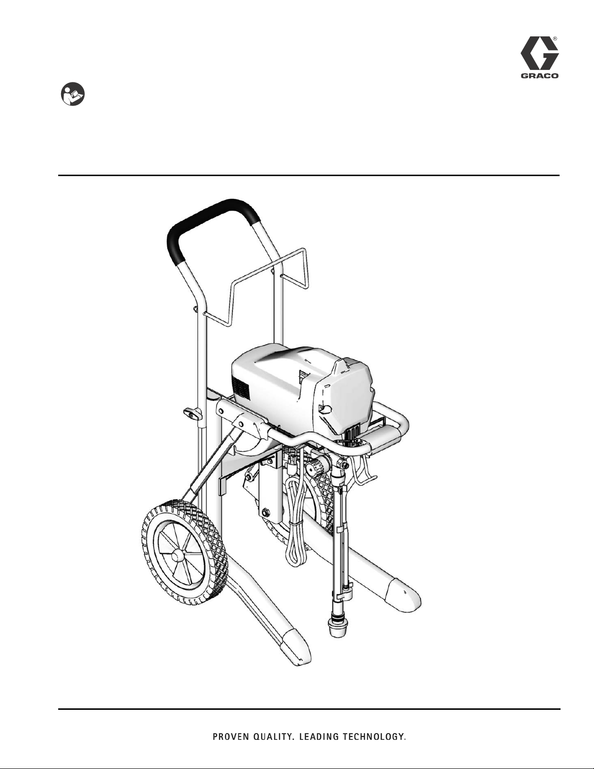
Instructions
Important Safety Instructions
Read all warnings and instructions in this manual and in the
sprayer operation manual. Save these instructions.
Lacquer Conversion Kit 256212
312933D
EN
ti11870a
Page 2
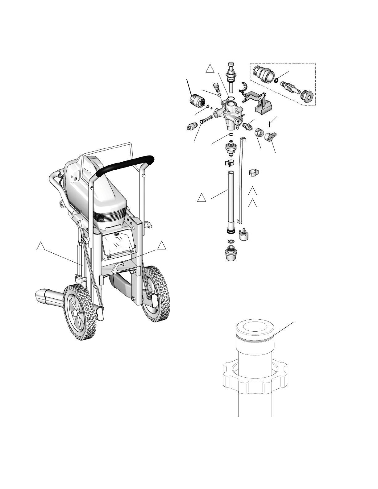
Lacquer Conversion Kit 256212
Qty
Ref. Part No. Description
1 117559 O-RING, CV-75, size 020 2
2 111507 O-RING, CV-75, size 013 1
3 111316 O-RING, CV-75, size 012 1
4 15D370 O-RING, CV-75, size 022 1
5 15D371 O-RING, CV-75, size 015 2
6 15D252 O-RING, CV-90, size 008 1
7 119400 SEALANT, pipe, sst 1
8 15D883 TUBE, suction 1
See Pressure
.
Control
Replacement
1
4
2
3
5
1
2
8
D
C
1
Apply light coat of lithium-based grease
2
Do not use hook storage with new suction
tube as it is not flexible enough to allow
for bending. Damage will occur.
6
B
A
2
2
ti11871a
240V Sprayers Only
ti11872a
1
2 312933D
Page 3

Pressure Relief Procedure
To help prevent injection injuries, follow this procedure
when you stop spraying and before you service or
clean the sprayer, remove parts, or repair leaks.
1. Turn power switch to OFF.
2. Unplug sprayer.
3. Turn knob (A) down to PRIME/DRAIN.
4. Hold metal part of gun firmly to a grounded metal
pail. Pull gun trigger to relieve pressure.
Instructions
1. Turn knob (A) up to SPRAY position.
2. Remove pin (B) with pin punch and hammer.
B
5. Replace brown o-ring (6) on end of valve stem.
Apply sealant (7) to valve threads. Install valve stem
in pump manifold. Torque to 185 in-lb (21 N•m).
6. Install base (C) on valve, aligning pin (E) on base
(C) with hole (F) on manifold.
F
E
7. Rotate valve stem with a pin punch until hole is perpendicular.
C
A
3. Remove knob (A) and base (C).
C
4. Remove valve stem (D) from manifold. Be sure gasket (X) and seat (Z) do not stay in manifold.
B
A
Z
X
D
8. Install knob (A) over base (C).
9. Place knob in SPRAY position.
10. Insert end of pin punch through hole in knob (A), to
make sure knob and valve stem are aligned.
A
11. Install pin (B) through hole in knob (A). Tap pin
through knob with hammer. End of pin will be flush
with top of hole in knob when correctly installed.
312933D 3
Page 4

X5, X7, LTS 15, and LTS 17 Pressure Control Replacement
Disassembly
1. Unplug electrical cord and Relieve Pressure. See
Pressure Relief Procedure on page 3.
2. X7 and LTS 17 Only: Remove underside shroud
mounting screw (D).
3. Remove side shroud screws (E) (T-20 Torx).
4. Remove 4 front cover screws (F) (T-30 Torx).
5. Remove shroud (G).
6. Disconnect power cord connectors (H) from
ON/OFF switch (L).
7. Remove shroud (K).
8. Series A: Remove 2 pump housing mounting
screws (ps). Be sure to support pump housing (ph).
9. Series A: Remove pump housing (ph). X7 and LTS
17 Only: Pull power cord (N) through opening in
pump housing mounting bracket (pb).
10. Disconnect pressure control harness from control
board connector (cb). Take note of wire routing; new
wires will be rerouted the same way.
11. Series A: Remove AutoPrime cover (A) by releas-
ing tab underneath pressure control knob.
Series B: Release tab underneath function indicator
(fi) and remove indicator and front cover.
12. Turn pressure control knob fully counterclockwise to
expose wrench flats. Remove pressure control (P).
Verify the o-ring seal (or) has been removed from
the pump (J).
nect to control board connectors (cb) (connect with
tab in front). Install AutoPrime cover (A) and latch
tab.
4. Install pump housing (ph) with 2 pump housing
mounting screws (ps) onto pump housing mounting
bracket (pb). Torque to 110 to 120 in-lb (12.4 to 13.6
N•m).
5. Series B: Route pressure control harness through
function indicator (fi) and front cover. Install indicator
on pump and snap together. Align indicator and
front cover as they are positioned loosely on pump.
Connect harness to control board terminals (cb).
6. Reattach power cord connectors (H) to ON/OFF
switch (L).
7. Install shroud (K).
8. X7 and LTS 17 Only: Route power cord (N) through
opening in pump housing mounting bracket (pb).
9. Install power cord (N) into recess on left shroud (K).
10. Install shroud (G) to shroud (K) and front cover.
11. Install side shroud screws (E) (T-20 Torx). Torque to
20 to 25 in-lb (2.3 to 2.8 N•m).
12. Install 4 front cover screws (F) (T-30 Torx). Torque
to 26 to 32 in-lb (2.9 to 3.6 N•m).
13. X7 and LTS 17 Only: Install underside shroud
mounting screw (D). Torque to 25 to 35 in-lb (2.8 to
3.9 N•m).
14. Turn pressure control switch knob (P) clockwise as
far as it will go. Apply pressure control label (cl) to
knob. To position label correctly, see note below:
Assembly
NOTICE
Do not pinch wires between pressure control (P) and
pump housing (ph) pump mounting bracket (pb) and
shrouds (G and K) while assembling.
1. Examine new pressure control (P) to verify o-ring
seal (or) is in place. If o-ring seal is not installed on
pressure control, install seal.
2. Apply one or two drops of thread locking adhesive
(included in kit) to threads of pressure control switch
(P). Assemble pressure control switch (P) into pump
(J). Torque to 140-160 in.-lbs (16-18 N•m).
3. Series A: Route pressure control (P) harness as
shown in harness routing detail on page 12. Con-
4 312933D
NOTE: When properly positioned, the function indicator
(fi) and hi-spray position symbol on pressure control
label (cl) are aligned.
fi
hi-spray symbol
cl
P
ti10041a
Page 5

X5 and LTS 15 Model Sprayers (Series A unit shown)
F
G
E
ps
N
ph
J
Tab
A
L
H
K
or
P
ti11886a
X7 and LTS 17 Model Sprayers (Series A unit shown)
E
G
ps
N
pb
H
D
ph
Ta b
A
L
K
F
J
or
P
ti11887a
312933D 5
Page 6

X5, X7, LTS15, and LTS17 (Series A) Wire Routing
cb
A
ti11888a
Ta b
Graco Information
For the latest information about Graco products, visit www.graco.com
TO PLACE AN ORDER, contact your Graco distributor or call 1-800-690-2894 to identify the nearest distributor.
All written and visual data contained in this document reflects the latest product information available at the time of publication.
GRACO INC. AND SUBSIDIARIES • P.O. BOX 1441 • MINNEAPOLIS MN 55440-1441 • USA
Copyright 2008, Graco Inc. All Graco manufacturing locations are registered to ISO 9001.
Graco reserves the right to make changes at any time without notice.
For patent information, see www.graco.com/patents.
Original instructions. This manual contains English. MM 312933
Graco Headquarters: Minneapolis
International Offices: Belgium, China, Japan, Korea
www.graco.com
Revised September 2013
 Loading...