

Page 1
Instructions - Parts
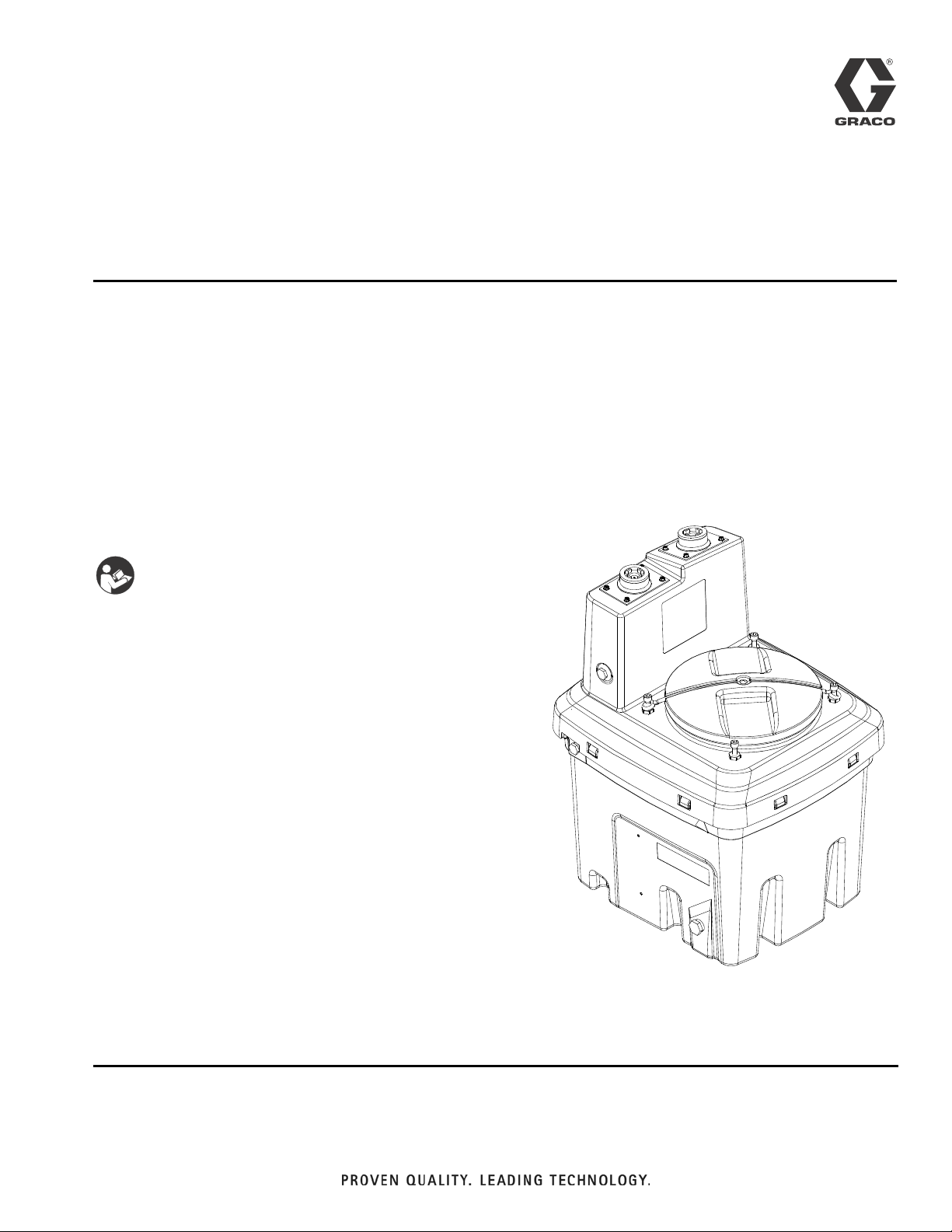
Double Wall Hopper
For use with XM™ plural-component sprayers and immersion heaters.
For professional use only.
255963, Double Wall Hopper
20 Gallon (75 liter) Spray Material Fluid Capacity
12 Gallon (45 liter) Heated Material Fluid Capacity
See page 12 for optional accessories and approvals.
Important Safety Instructions
Read all warnings and instructions in this manual.
Save these instructions.
312747L
EN
Page 2

Related Manuals
Contents
Related Manuals . . . . . . . . . . . . . . . . . . . . . . . . . . . 2
Optional Accessories . . . . . . . . . . . . . . . . . . . . . . . 3
Warnings . . . . . . . . . . . . . . . . . . . . . . . . . . . . . . . . . 4
Keep Components A and B Separate . . . . . . . . . 6
Changing Materials . . . . . . . . . . . . . . . . . . . . . . . 6
Component Identification . . . . . . . . . . . . . . . . . . . . 7
Double Wall Hoppers Mounted on Side of Frame 7
Overview . . . . . . . . . . . . . . . . . . . . . . . . . . . . . . . . . . 8
Installation . . . . . . . . . . . . . . . . . . . . . . . . . . . . . . . . 9
Optional Accessories . . . . . . . . . . . . . . . . . . . . 12
Setup . . . . . . . . . . . . . . . . . . . . . . . . . . . . . . . . . . . . 14
Connect Return Tube and Recirculation Hose . 14
Fill Heating Fluid . . . . . . . . . . . . . . . . . . . . . . . . 15
Fill Spray Material . . . . . . . . . . . . . . . . . . . . . . . 16
Operation . . . . . . . . . . . . . . . . . . . . . . . . . . . . . . . . 17
Startup . . . . . . . . . . . . . . . . . . . . . . . . . . . . . . . 17
Flush Hopper . . . . . . . . . . . . . . . . . . . . . . . . . . 17
Shutdown . . . . . . . . . . . . . . . . . . . . . . . . . . . . . 17
Maintenance . . . . . . . . . . . . . . . . . . . . . . . . . . . . . . 18
Check Heating Fluid Level . . . . . . . . . . . . . . . . 18
Check for Heating Fluid Leakage . . . . . . . . . . . 18
Drain Heating Fluid . . . . . . . . . . . . . . . . . . . . . . 18
Drain Spray Material . . . . . . . . . . . . . . . . . . . . . 19
Repair . . . . . . . . . . . . . . . . . . . . . . . . . . . . . . . . . . . 20
Remove Immersion Heater . . . . . . . . . . . . . . . . 20
Remove Fluid Outlet Assembly Kit . . . . . . . . . . 20
Remove Hopper . . . . . . . . . . . . . . . . . . . . . . . . 21
Replace Gaskets . . . . . . . . . . . . . . . . . . . . . . . . 21
Troubleshooting . . . . . . . . . . . . . . . . . . . . . . . . . . . 22
Parts . . . . . . . . . . . . . . . . . . . . . . . . . . . . . . . . . . . . 24
Accessories . . . . . . . . . . . . . . . . . . . . . . . . . . . . . . 28
Technical Data . . . . . . . . . . . . . . . . . . . . . . . . . . . . 29
Dimensions . . . . . . . . . . . . . . . . . . . . . . . . . . . . 29
Graco Standard Warranty . . . . . . . . . . . . . . . . . . . 32
Graco Information . . . . . . . . . . . . . . . . . . . . . . . . 32
Related Manuals
Manuals are available at www.graco.com.
Component Manuals in English:
Manual Description
312359 XM Operation
313289 XM Repair
313292 XM OEM, Instructions-Parts
309524 Viscon HP Heater, Instructions-Parts
312769
406739 Desiccant Dryer Kit, Instructions-Parts
313259
Feed Pump and Agitator Kits, Instructions-Parts
Hopper or Hose Heat Circulation Kit,
Instructions-Parts
2 312747L
Page 3
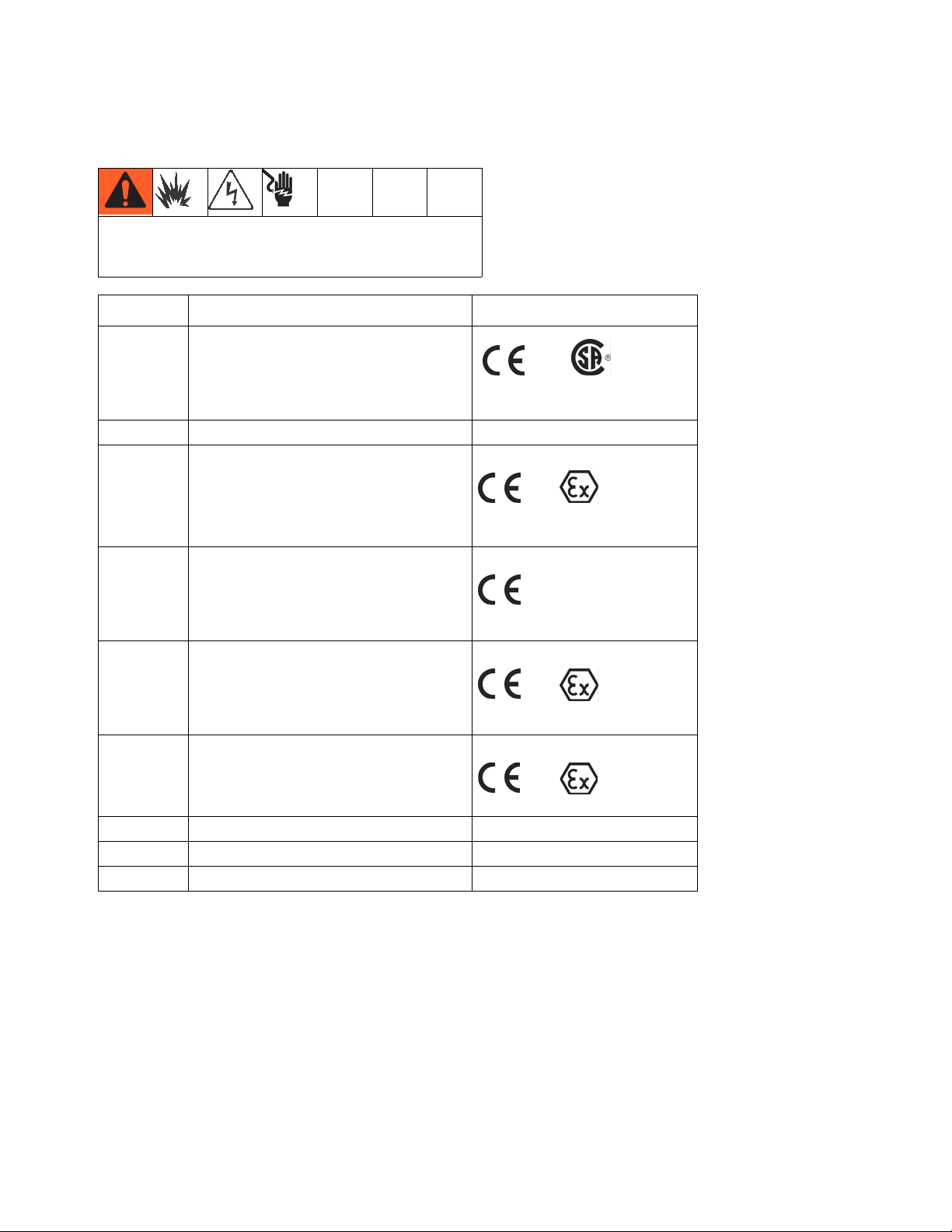
Optional Accessories
Not all accessories and kits are approved for use in
hazardous locations. Refer to the specific accessory
and kit manuals for approval details.
Part Description Approvals
256257 240V 1 PH Immersion Heater
(For heater 121376.)
256512 Desiccant Kit N/A
256274 Agitator Kit
CUS
207901
Optional Accessories
0359
(For agitator 224854.)
256275 T2 2:1 Ratio Transfer Pump Kit
(For pump 295616.)
256276
Monark
®
5:1 Ratio Transfer Pump Kit
0359
(For pump 218956.)
239326
10:1 Ratio President
®
Pump
0359 II 1/2 G T2
15V074 Hopper Outlet Plug Not applicable
262824 Hopper Stand Not applicable
262820 Flexible Fluid Connection Kit Not applicable
See Accessories on page 28 for parts lists.
II 1/2 G T3
ITS03ATEX11226
II 1/2 G T2
ITS03ATEX11228
ITS03ATEX11228
Not approved for use in explosive atmosphers or hazardous locations
312747L 3
Page 4
Warnings
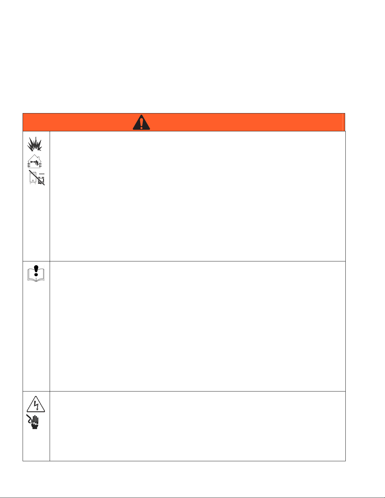
Warnings
The following warnings are for the setup, use, grounding, maintenance, and repair of this equipment. The exclamation point symbol alerts you to a general warning and the hazard symbol refers to procedure-specific risk. Refer back
to these warnings. Additional, product-specific warnings may be found throughout the body of this manual where
applicable.
WARNING
WARNINGWARNINGWARNING
FIRE AND EXPLOSION HAZARD
Flammable fumes, such as solvent and paint fumes, in work area can ignite or explode. To help prevent
fire and explosion:
• Use equipment only in well ventilated area.
• Eliminate all ignition sources; such as pilot lights, cigarettes, portable electric lamps, and plastic drop
cloths (potential static arc).
• Keep work area free of debris, including solvent, rags and gasoline.
• Do not plug or unplug power cords, or turn power or light switches on or off when flammable fumes
are present.
• Ground all equipment in the work area. See Grounding instructions.
• Use only grounded hoses.
• Hold gun firmly to side of grounded pail when triggering into pail.
• If there is static sparking or you feel a shock, stop operation immediately. Do not use equipment
until you identify and correct the problem.
• Keep a working fire extinguisher in the work area.
• Not for use in explosive atmospheres unless all components and wiring are appropriately approved.
EQUIPMENT MISUSE HAZARD
Misuse can cause death or serious injury.
• Do not operate the unit when fatigued or under the influence of drugs or alcohol.
• Do not exceed the maximum working pressure or temperature rating of the lowest rated system
component. See Technical Data in all equipment manuals.
• Use fluids and solvents that are compatible with equipment wetted parts. See Technical Data in all
equipment manuals. Read fluid and solvent manufacturer’s warnings. For complete information
about your material, request MSDS forms from distributor or retailer.
• Check equipment daily. Repair or replace worn or damaged parts immediately with genuine manufacturer’s replacement parts only.
• Do not alter or modify equipment.
• Use equipment only for its intended purpose. Call your distributor for information.
• Route hoses and cables away from traffic areas, sharp edges, moving parts, and hot surfaces.
• Do not kink or over bend hoses or use hoses to pull equipment.
• Keep children and animals away from work area.
• Comply with all applicable safety regulations.
ELECTRIC SHOCK HAZARD
This equipment must be grounded. Improper grounding, setup, or usage of the system can cause
electric shock.
• Turn off and disconnect power at main switch before disconnecting any cables and before servicing
equipment.
• Connect only to grounded power source.
• All electrical wiring must be done by a qualified electrician and comply with all local codes and regulations.
4 312747L
Page 5
Warnings
WARNING
WARNINGWARNINGWARNING
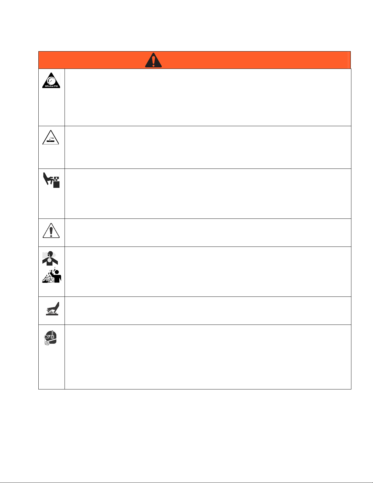
PRESSURIZED EQUIPMENT HAZARD
Fluid from the gun/dispense valve, leaks, or ruptured components can splash in the eyes or on skin and
cause serious injury.
• Follow Pressure Relief Procedure in this manual, when you stop spraying and before cleaning,
checking, or servicing equipment.
• Tighten all fluid connections before operating the equipment.
• Check hoses, tubes, and couplings daily. Replace worn or damaged parts immediately.
PLASTIC PARTS CLEANING SOLVENT HAZARD
Use only compatible water-based solvents to clean plastic structural or pressure-containing parts. Many
solvents can degrade plastic parts and cause them to fail, which could cause serious injury or property
damage. See Technical Data in this and all other equipment instruction manuals. Read fluid and solvent
manufacturer’s warnings.
MOVING PARTS HAZARD
Moving parts can pinch or amputate fingers and other body parts.
• Keep clear of moving parts.
• Do not operate equipment with protective guards or covers removed.
• Pressurized equipment can start without warning. Before checking, moving, or servicing equipment,
follow the Pressure Relief Procedure in this manual. Disconnect power or air supply.
SUCTION HAZARD
Never place hands near the pump fluid inlet when pump is operating or pressurized. Powerful suction
could cause serious injury.
TOXIC FLUID OR FUMES HAZARD
Toxic fluids or fumes can cause serious injury or death if splashed in the eyes or on skin, inhaled, or
swallowed.
• Read MSDS’s to know the specific hazards of the fluids you are using.
• Store hazardous fluid in approved containers, and dispose of it according to applicable guidelines.
• Always wear impervious gloves when spraying or cleaning equipment.
BURN HAZARD
Equipment surfaces and fluid that’s heated can become very hot during operation. To avoid severe
burns, do not touch hot fluid or equipment. Wait until equipment/fluid has cooled completely.
PERSONAL PROTECTIVE EQUIPMENT
You must wear appropriate protective equipment when operating, servicing, or when in the operating
area of the equipment to help protect you from serious injury, including eye injury, inhalation of toxic
fumes, burns, and hearing loss. This equipment includes but is not limited to:
• Protective eyewear
• Clothing and respirator as recommended by the fluid and solvent manufacturer
•Gloves
• Hearing protection
312747L 5
Page 6

Warnings
Keep Components A and B Separate
NOTICE
To prevent cross-contamination of the equipment’s
wetted parts, never interchange component A and
component B.
Changing Materials
• When changing materials, flush the equipment multiple times to ensure it is thoroughly clean.
• Check with your material manufacturer for chemical
compatibility.
• Some materials use catalyst on the A side, but
some applications may use catalyst on the B side.
6 312747L
Page 7
Component Identification
Double Wall Hoppers Mounted on Side of Frame
Component Identification
R
H
A
C
H
J
D
G
J
K
D
N
P
L
E
M
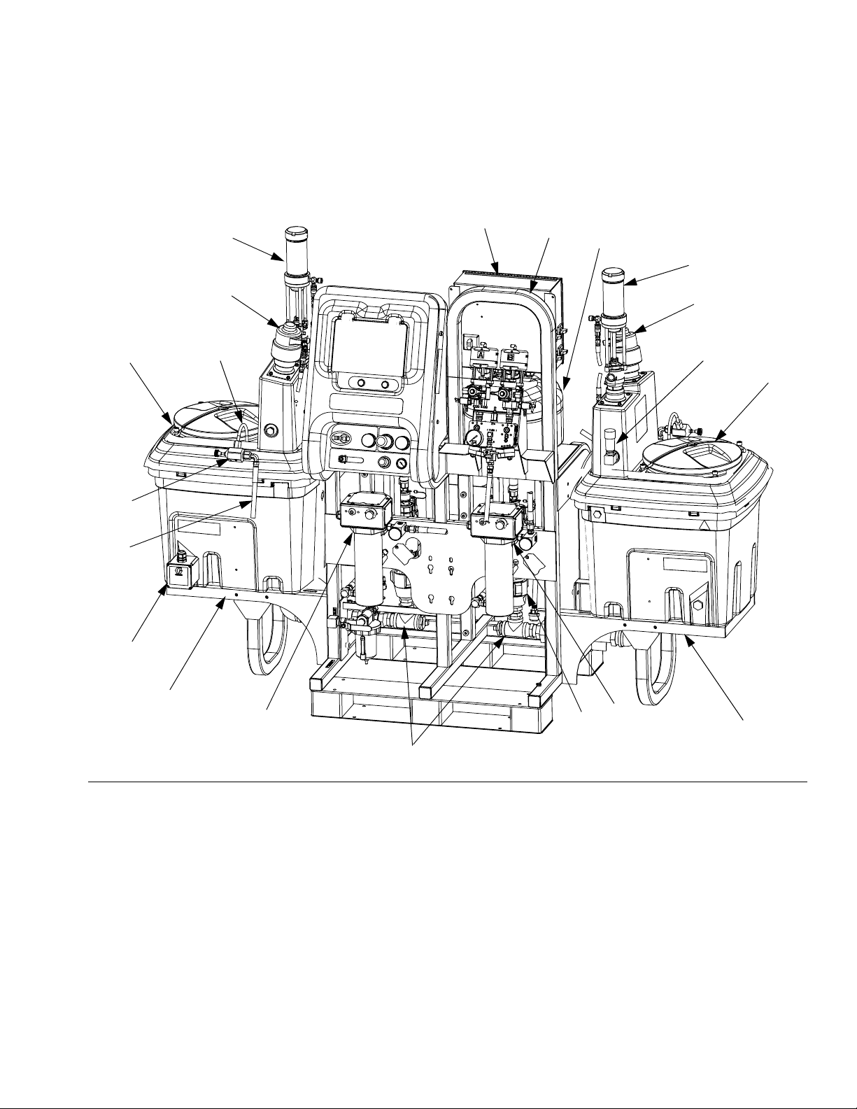
FIG. 1: Typical Installation
Key:
AFrame
BXtreme® lower (behind the frame)
CNXT
D Double wall hopper
E Universal hopper mounting kit
F Fluid inlet assembly
G Return tube
H Feed pump
J Agitator
K Desiccant dryer
L Immersion heater
M Fluid heater
™
air motor (behind the frame)
M
B
E
F
N Restrictor valve (recirculation return)
P Recirculation hose
R Junction box
312747L 7
Page 8
Overview
Overview
Double wall hoppers (D) can be mounted on the back or
side of the frame (A) to gravity feed spray material to the
Xtreme lower (B). Feed pumps (H) and agitators (J) can
be mounted on top of the hoppers to pressure feed
spray material directly to the pump.
A strainer inside the hopper (D) prevents objects larger
than 1/4 in. from clogging or damaging pumps. When
the XM sprayer is running, spray material exits the hopper through the fluid inlet assembly or transfer pump and
circulates through the lowers (B), mix manifold, fluid
heaters (M), and returns to the hopper (D) through the
recirculation hose (P). Immersion heaters (L) installed
through the sides of the hopper help to maintain the
temperature of the spray material during recirculation.
XM sprayers are not approved for use in hazardous
locations unless the base model, all accessories, all
kits, and all wiring meet local, state, and national
codes.
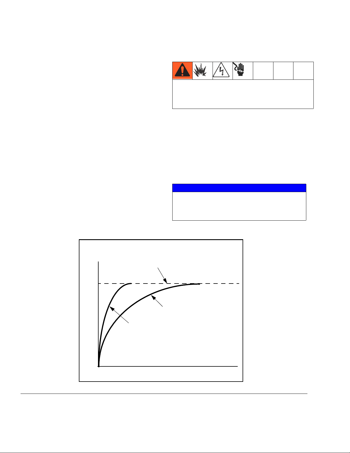
Oil or a 50% water and 50% ethylene glycol mixture can
be added to the hopper’s outer cavity to a controlled
temperature and help maintain the temperature of the
spray material. The heated fluid in the outer jacketed
area helps prevent heat loss of the spray material.
A 50% mixture of water and ethylene glycol mixture
heats up faster than typical hydraulic oil. See F
IG. 2.
Spray material temperature
Temperature
50/50 water mixture
NOTICE
Use the Hopper or Hose Heat Circulation Kit 256273
to heat the hopper outer cavity fluid or special fluid
hoses in hazardous environments. See manual
313259 for installation and repair parts.
Oil
Time
FIG. 2: Heated Fluid Temperature Comparison
8 312747L
Page 9
Installation
Installation
Hopper mounting kit 256259 allows the hoppers (D) to
mount on the sides or back of the frame (A).
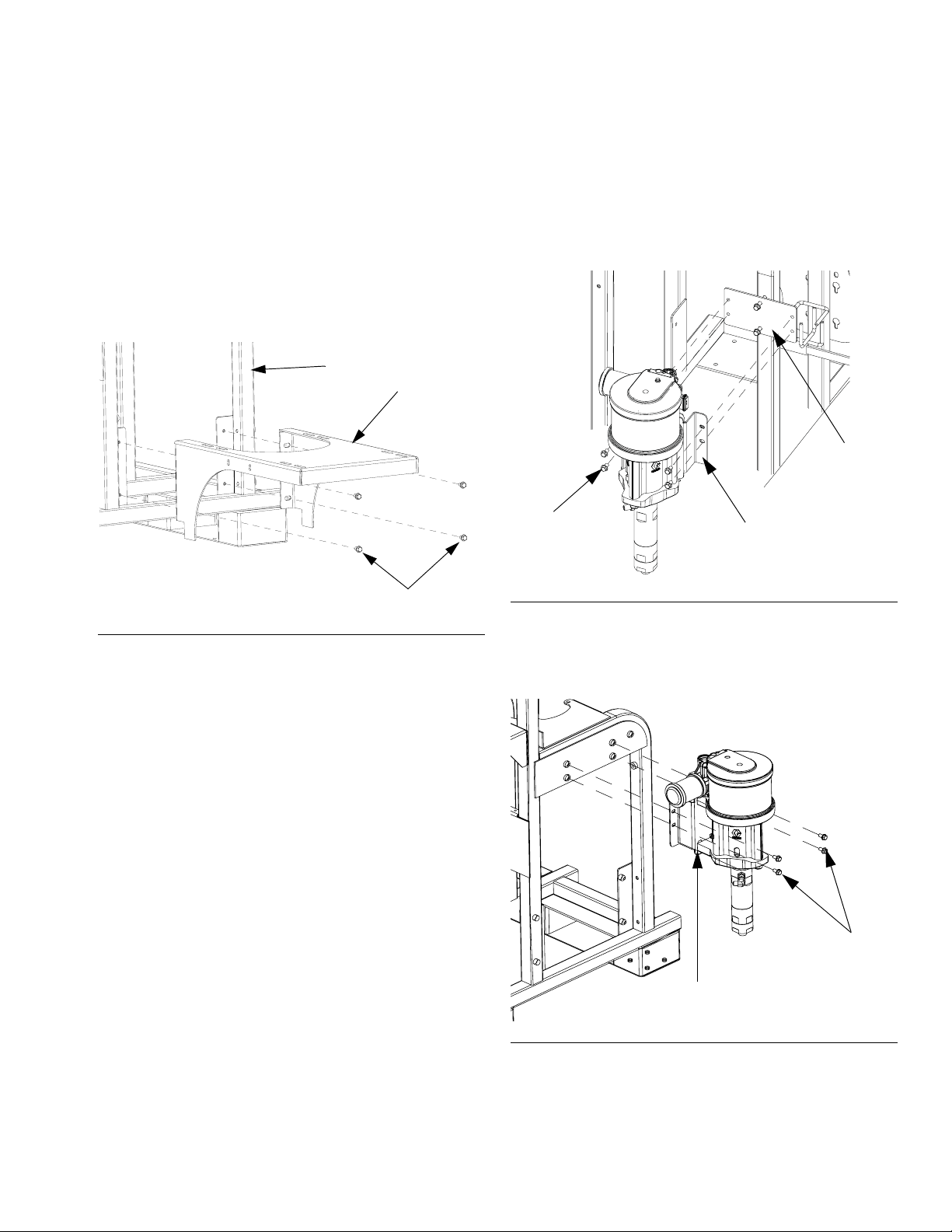
1. Mount hoppers (D) on sides of the frame (A). See
F
IG. 3.
a. Attach main bracket (101) to frame (A) with
screws (107).
A
F
IG. 3: Sides of Frame
b. Repeat for second hopper (D) on opposite side
of frame (A).
101
107
a. Remove four screws (306) holding solvent
pump bracket (307) to mounting plate (308).
Leave pump attached to bracket. Remove pump
and bracket.
308
306
307
FIG. 4: Remove Solvent Pump
b. Use four screws (306) to attach solvent pump
and bracket (307) to side of frame.
2. Mount hoppers (D) on back of the frame (A). See
F
IG. 6.
NOTE: The solvent pump must be moved to the side
of the frame before the hoppers can be mounted to
the back. Follow sub-steps a and b to move the solvent pump to either side of the frame.
307
IG. 5: Attach Solvent Pump to Side of Frame
F
306
312747L 9
Page 10
Installation
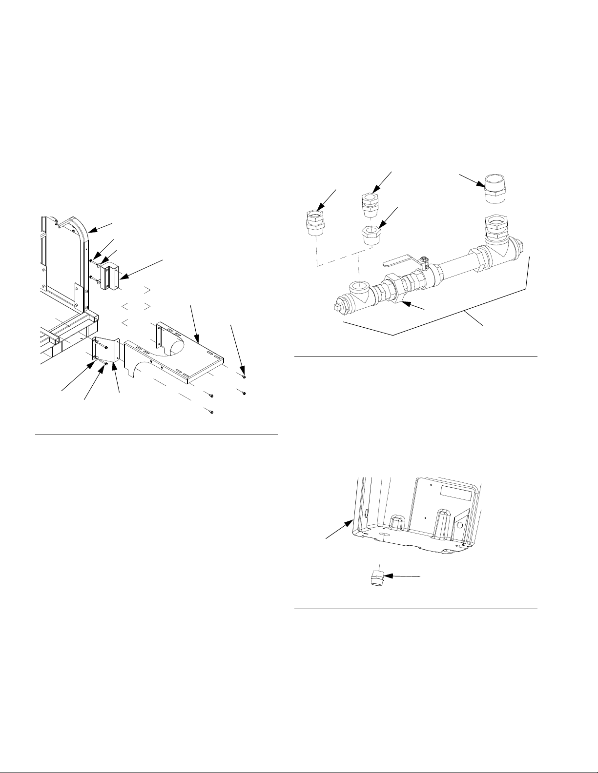
c. Attach the corner bracket (103) to frame (A) with
screws (108) and washers (110).
d. Attach lower mount bracket (104) to frame (A)
with screws (108) and washers (110).
e. Attach main bracket (101) to frame (A) with
screws (107).
f. Repeat steps b and c for second hopper (D).
A
108
110
103
101
107
3. Connect reducing swivel (211) to fluid outlet assembly (F) if your system uses a 50:1 pump. Connect
reducer bushing fitting (212) and swivel fitting (215)
to fluid outlet assembly (201) if your system uses a
70:1 pump. Do not use pipe sealant on swivel end of
swivel fittings.
215
201
211
212
208
F
IG. 7: Connect Fluid Outlet Assembly to Lower
F
110
108
F
IG. 6: Back of Frame
104
4. Loosen union (208).
5. Connect swivel fitting (211 or 215) to pump foot
valve. See F
IG. 7.
6. Apply pipe sealant paste to one end of nipple
threads (201) and install that end in bottom of hopper (D).
D
201
F
IG. 8: Install Nipple
10 312747L
Page 11

Installation
7. Align holes on main bracket (101) and thread inserts
of the hopper (D). Loosely fasten hopper (D) to
bracket (101) with four screws (107) and washers
(110).
D
101
110
107
IG. 9: Attach Hopper to Bracket
F
8. Connect swivel fitting (202) to nipple (201).
9. Tighten union (208) and ensure fluid outlet assembly is aligned. See F
10. Tighten hopper mounting screws (107). See F
IG. 7 on page 10.
IG. 9.
11. Install screws (107) and bottom support (109).
107
D
107
109
IG. 11: Install Bottom Support
F
201
202
IG. 10: Connect Fluid Inlet Assembly to Hopper
F
12. Repeat steps 3-11 for second hopper (D).
312747L 11
Page 12

Installation
Optional Accessories
See Accessories page 28 for a list of all accessories
that can be used with double wall hoppers.
Immersion Heater Kit 256257
The immersion heater (L) is only approved for
non-explosive atmosphere applications. Using the
immersion heater in hazardous locations, or explosive
atmospheres, may cause ignition or explosion.
• For hazardous environments use the Hopper or
Hose Heat Circulation Kit 256273; see manual
312359.
• Ensure the outer cavity of the hopper is empty
before installing immersion heater to prevent oil or
water mixture from exiting hopper.
Immersion heater kit 256257 can only be used with a
water mixture or oil in the outer jacketed area of the hopper.
4. Install bushing (302) in top of wiring outlet. Route
power cable (303) through bushing (302).
D
28
FIG. 12: Immersion Heater
5. Remove screws (HS) and immersion heater cover
(HC).
HS
L
HC
302
1. Remove plug (28) from side of hopper (D).
2. Apply thread sealant to immersion heater threads
(L) and screw immersion heater into hopper (D).
3. After installation, remove plug (28) from opposite
side and verify element end is visible through plug
hole.
NOTICE
Vertically orientate wiring outlet. Ensure bushing (302)
is positioned on top of the immersion heater (L) before
installing the cover (HC). Failing to do so will allow overheating, and therefore the overtemperature switch will
trip.
Do not bend heating elements during installation. Bent
elements may cause hopper wall failure allowing spray
material to contact heater.
IG. 13: Immersion Heater Cover
F
6. Connect white and black wires from cable (303) to
white wires inside immersion heater box. Tighten
together with wire nuts (304).
7. Connect green wire from cable (303) and green wire
inside immersion heater box. Tighten together with
with wire nut (304).
12 312747L
Page 13

8. Set thermostat knob (TK) to desired spray material
conditioning temperature. Align temperature setting
to set point (SP).
NOTE: Set point (SP) is a “V” notch in the metal
bracket at the top of the thermostat dial. Maximum
setting is 140°F (60°C).
303
Installation
TK
L
IG. 14: Connect Immersion Heater
F
HC
SP
9. Install immersion heater cover (HC) with screws
(HS). See F
IG. 13.
10. Open junction box door and remove plug for appropriate heater wire. Install cord grip of bushing (302).
Route power cable (303) up through cord grip.
BA
BB
302
303
FIG. 15: Immersion Heater Power Cables
11. Press the top lever up on the power switch body
(BA, BB) and pull away from the junction box. Install
by pushing the power switch body onto the switch
lever post. Flip lever down to engage.
12. Loosen lugs 2 and 4 on immersion heater A power
switch (BA) or immersion heater B power switch
(BB). Insert power leads and tighten lugs.
13. Connect green wire to 102GND grounding lug.
Feed Pump and Agitator Kits
See manual 312769 for installation and operation
instructions.
312747L 13
Page 14

Setup
Setup
1. Remove the large A or B label from the label sheet
(24) and apply to front face of the appropriate hopper to help avoid filling the wrong materials and
causing cross-contamination.
24
F
IG. 16: Apply Label
2. Remove the small A or B from the label sheet (24)
and apply on lid.
Connect Return Tube and
3. Connect other end of recirculation hose to recirculation valve (V) on XM sprayer.
R
R
V
F
IG. 18: Recirculation Hose and Recirculation Valve
4. Repeat for second hopper.
Recirculation Hose
1. Install return tube (G) in port on top of hopper (D).
G
P
D
R
F
IG. 17: Connect Return Tube and Recirculation
Hose
2. Connect recirculation hose (R) and recirculation
restrictor valve (P) to return tube (G).
14 312747L
Page 15

Setup
Fill Heating Fluid
Fill the hopper’s outer jacketed area with oil or a 50%
water and 50% ethylene glycol mixture to heat your
spray material. The double wall hopper design prevents
the spray material from losing heat during downtime and
overnight.
NOTICE
Algae can form inside the outer jacketed area if you
are using only water to heat your spray material.
Always add ethylene glycol to the water to prevent
the formation of algae.
Replace heating fluid inside hopper once a year to
improve heating efficiency. See Check Heating
Fluid Level on page 18.
Table 1: Fluid Capacities of 20 Gal. Hopper
Gallons (Liters) of
Heating Fluid
12 (45) 20 (76)
Gallons (Liters) of
Spray Material
3. Fill outer jacketed area of the hopper through the filling port until the fluid reaches the opposite fill port
when using the Immersion Heater Kit 256257,
page 12.
NOTICE
Do not fill the outer jacketed area fully if using the
hopper or hose circulation kit. See fill instructions in
the Hopper or Hose Circulation Kit manual. Overfilling may cause heating fluid to overflow vent fittings
(see F
IG. 21) during startup.
NOTICE
Do not plug top ports. Always have venting fittings
(36, 39) installed to prevent outer cavity pressurization. Failure to do so may cause leakage into spray
material.
4. Vent fittings may be installed on either side. See
F
IG. 21 for correct orientation of venting fittings.
1. Remove plug (6) from opposite end of 3/4 npt filling
port.
6
F
IG. 19: Filling Overflow Port
2. Insert fluid hose into one filling port and place an
empty 5 gallon pail beneath opposite filling port to
catch access fluid from filling port.
39
36
F
IG. 20: Install Venting Fittings
312747L 15
Page 16

Setup
Left Side
Shown
(45°)
Open Port
F
IG. 21: Orientation of Venting Fittings
5. Install plug (6) in opposite port and torque to 20-30
ft-lbs (27-41 N•m).
NOTE: Occasionally inspect the inside of the hopper
for any leakage of outer cavity heating fluid.
Fill Spray Material
Condition materials prior to adding to hoppers. Ensure
resin materials are thoroughly agitated, homogenous,
and pourable prior to adding to hopper. Stir hardeners
back into suspension prior to adding material to hopper.
1. Disconnect spring strap (7) from front post and
remove lid (1c). Keep connected to lanyard (10).
10
7
1c
F
IG. 22: Remove Lid
2. Pour desired amount of spray material through
strainer inside hopper (D). See Table 1: Fluid
Capacities of 20 Gal. Hopper.
D
IG. 23: Fill Spray Material
F
3. Tightly secure lid (1c) on hopper (D) and reconnect
spring strap (7).
16 312747L
Page 17

Operation
Operation
Startup
1. Ensure that the outer jacketed area is filled with
water mixture or oil and the accessories are correctly installed.
2. Follow Setup procedure in manual 312359.
3. See manual 312359 for testing material and operation instructions before spraying material.
Flush Hopper
1. Drain Spray Material. See page 19.
2. Flush hoppers and fluid inlet assemblies (F) with
compatible solvent before switching materials or
cleaning hopper (D). See Flushing section in manual 312359.
3. Visually inspect the inside of the empty hopper for
any leakage of outer cavity heating fluid.
Shutdown
1. See Shutdown and Pressure Relief procedures in
manual 312359.
312747L 17
Page 18

Maintenance
Maintenance
Drain Heating Fluid
1. Turn off all heaters and allow heating fluid to cool for
a minimum of 8 hours.
Check Heating Fluid Level
Gradual fluid evaporation can occur, therefore, check
the level of heating fluid monthly.
1. Remove plug (6).
2. Place flexible object in port so that it protrudes
down. Pull out to observe level.
3. Refill heating fluid as necessary. See Fill Heating
Fluid, page 15, for instructions.
Check for Heating Fluid Leakage
When spray material is drained and heating fluid is full,
inspect the inside of the hopper for any signs of heating
fluid leakage.
2. Place either a 1-gallon (4-liter) or 3-gallon (7-liter)
pail directly beneath drain plug (37).
NOTE: Only 1-gallon (4-liter) pails fit beneath drain
plug if hoppers are mounted on the back of the
frame.
37
FIG. 24: Place Pail Beneath Drain Plug
3. Use wrench to hold reducer fitting (36) secure while
using another wrench to remove drain plug (37) and
capture heating fluid in pail.
4. Use additional pails as necessary until all fluid is
drained.
5. Install plug (37) into reducer fitting (36) after fluid is
completely drained from the hopper’s (D) outer jacketed area.
18 312747L
Page 19

Maintenance
Drain Spray Material
1. Flush and Shutdown XM sprayer. See XM opera-
tion manual.
2. Turn off all fluid heaters (S) and allow heating fluid to
cool for a minimum of 8 hours.
3. Place a clean 1 gallon (4 liter) pail directly beneath
union (208) and ball valve (206).
4. Close ball valve (206) and open union (208) with
wrench.
206
208
F
IG. 25: Closed Ball Valve
5. Drain spray material from pump lower in pail. If necessary, remove fittings from opposite end, then use
a brush and compatible solvent to clean out fittings.
206
FIG. 27: Drain Hopper
8. Use additional pails as necessary until all material is
drained.
9. Close ball valve (206) and use two wrenches to
retighten union (208).
F
IG. 26: Drain Lower
6. Use additional pails as necessary until material is
drained.
7. Open ball valve (206) and drain spray material from
hopper. If necessary, remove plug from opposite
end, then use a brush and compatible solvent to
clean out plug and fittings.
312747L 19
Page 20

Repair
Repair
Remove Immersion Heater
1. Turn off power to system. See the XM Operation
manual.
2. Drain Heating Fluid. See page 18.
3. Remove screws (HS) and immersion heater cover
(HC).
303
302
HS
HC
FIG. 28: Connect Immersion Heater
Remove Fluid Outlet Assembly Kit
1. Drain Spray Material. See page 19.
2. Loosen fitting (212) or (211).
3. Loosen fitting (202).
4. See Installation on page 9 for assembly instruc-
tions.
211
IG. 29: Fluid Outlet Assembly
F
215
212
201
202
206
208
4. Disconnect white, black, and green wires from
power cable (303).
5. Loosen bushing (302) and pull power cable (303)
out of bushing.
6. Slowly remove immersion heater (L) from hopper
(D).
NOTICE
To prevent damage to the heater element coils,
ensure fold-back end of heater coil can pass back
through threaded opening of hopper (D).
7. Inspect the heater element coils for excessive corrosion. If necessary, replace entire immersion heater.
8. To install immersion heater (L) see Immersion
Heater Kit 256257 on page 12.
20 312747L
Page 21

Repair
Remove Hopper
1. Check Heating Fluid Level. See page 18.
2. Drain Spray Material. See page 19.
3. Disconnect swivel fitting (202). See F
4. If a transfer pump (H) or agitator (J) is mounted to
the hopper:
a. Relieve pressure. See manual 312769.
b. Disconnect air hoses from agitator and feed
pump. Disconnect fluid hose from feed pump.
5. Remove bolts (107) and washers (110) from under
mounting bracket (101).
IG. 29.
101
Replace Gaskets
The following procedure applies to both the hopper gaskets (13) and hopper lid gasket (12).
1. Remove old gasket and residual adhesive using
MEK solvent.
2. Clean groove in hopper using isopropyl alcohol. Let
air dry.
3. Remove adhesive backing from new gasket. Press
gasket firmly into groove. Be careful not to stretch
gasket material.
4. Trim excess length if necessary.
5. Reassemble rest of hopper parts to keep pressure
on gasket.
6. Allow 24 hours for full bonding.
110
110
F
IG. 30: Remove Hopper
6. Lift hopper (D) and carefully rest on a flat surface.
Use caution to avoid damaging fitting (201).
107
312747L 21
Page 22

Troubleshooting
Troubleshooting
Problem Cause Solution
Lid does not properly seal on hopper. Material build up. Remove built up material from gas-
Damaged gasket.
Material leaking between cover and
hopper.
Algae in water. Ethylene glycol was not added to
Immersion heater no longer heating. Overtemperature switch tripped on
Heating fluid leaking into spray material inside hopper.
Hopper is not heating all the way to
the top.
Gasket is not sealed properly. Check for built up material on gasket.
water.
immersion heater.
Inside wall of hopper is damaged. Replace hopper.
Heating fluid level is low. Refill heating fluid.
ket. Replace as necessary.
Replace as necessary.
Drain fluid. Add 50/50 water and eth-
ylene glycol mixture in outer cavity
Ensure it is mounted correctly. See
Immersion Heater Kit 256257, page
12.
Refill heating fluid level.
Locate heating fluid leak and correct.
If heating fluid level and immersion
heater is mounted correctly, remove
heater cover and press reset button.
Replace cover.
22 312747L
Page 23

Troubleshooting
312747L 23
Page 24

Parts
Parts
255963, Double Wall Hopper
1
Assemble with lips facing down.
2
Torque to 20-30 ft-lbs.
3
Clean groove with isopropyl alcohol
before applying gasket adhesive to
plastic. Cut to length.
35
19
9
32
32
8
7
10
1c
4
12
3
11
26
34
24
6
2
5
2
1b
14
1
6
2
13
3
39
2
36
2
1a
33
28
2
36
37
2
24 312747L
Page 25

255963, Double Wall Hopper
Ref. Part Description Qty
1a HOPPER 1
1b COVER 1
1c LID 1
4 255965 PLATE, weldment 2
5 15T007 ADAPTER, return tube 4
6 121621 PLUG, 3/4 in. npt 3
7 255966 STRAP, spring, hopper lid 1
8 109570 WASHER, plain; 1/2 in. 2
9 513764 SCREW, cap, socket head;
1/2-13 x 0.75
10 122097 CABLE, SST lanyard, 12 in. 1
11 256008 STRAINER 1
12 15T010 GASKET, lid, hopper 1
13 15T011 GASKET, hopper 2
14 15R403 SEAL, return tube 2
19 112547 SCREW, flange, hex head;
1/4-20 x 1
24 15R424 LABEL, A-B identification; not
shown
26 121378 PLUG, 2 in. npt, poly, w/gasket 2
28 121485 PLUG, 1 in. npt 2
32 121797 SCREW, cap, socket head;
1/2-13 x 1.5
33 189285 LABEL, caution 2
34 15R331 PLATE, accessory, hopper 2
35 104105 NUT, lock, hex; 1/4-20 8
36 117326 FITTING, bushing;
3/4 npt(m) x 1/2 npt(f)
37 100737 PLUG, pipe; 1/2 npt 1
39 158683 FITTING, elbow, 90 deg.;
1/2 npt (m-f)
40† 24K965 KIT, spacer, 5:1 pump (not shown) 1
Parts
1
8
1
2
2
2
Replacement Danger and Warning labels, tags, and
cards are available at no cost.
† Supplied spacer kit is for installation of a 5:1 pump
on this hopper. See manual 312769 for instructions.
312747L 25
Page 26

Parts
256259, Double Wall Hopper Mounting Kit
110
108
Back Mounted Double Wall Hopper
108
110
104
103
101
107
Side Mounted Double Wall Hopper
101
107
107
107
107
109
109
Ref. Part No. Description Qty.
101 256224 BRACKET, hopper, 20-gallon 1
103 256254 BRACKET, hopper, wldmt, bottom
mount
104 256256 BRACKET, hopper, bottom mount,
lower
107 112395 SCREW, cap, flng hd; 3/8-16 x 0.75 14
108 121488 SCREW, hex hd, flanged;
3/8-16 x 2.75
109 256928 SUPPORT, hopper bracket, rear 1
110 115625 WASHER, fender, 3/8 8
107
1
1
4
26 312747L
Page 27

256170, Universal Hopper Fluid Outlet Kit
215
211
212
216
207
206
205
Parts
201
202
217
203
204
208
207
210
209
Ref. Part No. Description Qty.
201 121435 NIPPLE, hex; 2 in. 1
202 121436 FITTING, swivel, male; 2 in. 1
203 121437 FITTING, tee, female; 2 in. 1
204 121438 BUSHING, reducer; 2 x 1 1/2 in. 1
205 121439 NIPPLE, pipe; 1 1/2 npt x 6 1
206 121440 VALVE, ball; 1 1/2 npt 1
207 121441 NIPPLE, hex; 1 1/2 npt 2
208 121442 FITTING, union; 1 1/2 npt 1
209 121443 FITTING, tee; 1 1/2 npt 1
210 101496 BUSHING, pipe; 1 1/2 x 3/4 npt 1
211* 121445 SWIVEL, reducing; 1 1/2 x 1 1/4 1
212† 121446 BUSHING, reducer; 1 1/2 x 1 1/4 1
215† 121447 FITTING, swivel; 1 1/4 1
216 104663 PLUG, pipe; 3/4 npt 1
217 123807 PLUG, pipe; 2 in. 1
* Parts used for 50:1 pumps only.
1
Apply sealant to all non-swiveling pipe threads.
2
Do not use pipe sealant on swivel fittings.
† Parts used with 70:1 pumps only.
312747L 27
Page 28

Accessories
Accessories
262820, Flexible Fluid Connection Kit
For gravity feeding from 20 gallon hopper to proportioner with Xtreme lower.
412
411
401
410
407
404
402
405
406
408
409
Ref Part Description Qty
401 120291 PIPE, elbow female 1
402 125995 FITTING, hose, barbed, 1-1/2 npt 2
403 126320 HOSE, 1-1/2 ID, 200 psi, 3 ft 1
404 126889 CLAMP, hose 2
405 121440 VALVE, ball, 1-1/2 npt 1
406 121441 FITTING, nipple, hex, 1-1/2 npt 1
407 121443 FITTING, tee, 1-1/2npt 1
408 101496 BUSHING, pipe 1
409 104663 PLUG, pipe 1
410 121445 SWIVEL, reducing, 1-1/2 x 1-1/4 1
411 121436 FITTING, swivel, male, 2 in. 1
412 121435 FITTING, nipple, hex, 2 in. 1
403
402
404
256512, Desiccant Kit
For removing moisture in replacement air for moisture-sensitive spray materials.
See manual 406739 for parts list.
Feed Pump and Agitator Kits
Part Description
256274 Agitator Kit
256275 T2 2:1 Ratio Transfer Pump Kit
256276
239326
See manual 312769 for installation and parts list.
Monark
President
®
5:1 Ratio Transfer Pump Kit
®
10:1 Ratio Transfer Pump
256260, 7 Gallon Hopper Kit
For mounting one seven gallon hopper to XM proportioner frame. Includes hopper, brackets, fasteners, and
fluid fittings.
See manual 406699 for parts list.
15V074, Hopper Outlet Plug
Plug is required when a 2:1 or 5:1 feed pump is used.
262824, Hopper Shroud
For mounting 20 gallon heated hopper independently.
256257, 240V 1 PH Immersion Heater Kit
For non-explosive atmospheres only. Includes
re-settable overtemperature switch.
1500 watts; 140°F (60°C) maximum temperature.
Ref. Part No. Description Qty.
301 121376 HEATER, hopper, 1 in. npt, 240V 1
302 116171 BUSHING, strain relief 2
303 15T968 CABLE, heater, hopper, 3 cond, 14
gauge
304 122032 NUT, wire 3
28 312747L
1
Page 29

Technical Data
20 Gallon Heated Compatible Hopper 256233
Maximum (continuous) temperature rating . . . . . . . . . . . . 140°F (60°C)
Maximum pressure rating (outer cavity) . . . . . . . . . . . . . . 0 psi (0 MPa, 0 bar)
Inner Tank Capacity (spray material) . . . . . . . . . . . . . . . . 22 gal. (83.3 liter)
Outer Jacketed Area Capacity (heating fluid). . . . . . . . . . 12 gal. (45.4 liter)
Outlet Port . . . . . . . . . . . . . . . . . . . . . . . . . . . . . . . . . . . . 2 npt anodized aluminum
Hopper Material . . . . . . . . . . . . . . . . . . . . . . . . . . . . . . . . Conductive polyethylene
Weight (dry) . . . . . . . . . . . . . . . . . . . . . . . . . . . . . . . . . . . 75.5 lb (34.2 kg)
Dimensions
Hopper
Technical Data
30 in.
(762 mm)
40 in.
(1016 mm)
14.5 in.
(368 mm)
18.2 in.
(462 mm)
ti19013a
312747L 29
Page 30

Technical Data
Hopper Stand Hopper on Stand
36 in.
(914 mm)
14.5 in.
(368 mm)
1.5 in.
(38 mm)
75.4 in.
(1915 mm)
26.5 in.
(673 mm)
17.5 in.
(445 mm)
1.5 in.
(38 mm)
42.3 in.
(1074 mm)
ti19011a
30 312747L
Page 31

Technical Data
312747L 31
Page 32

Graco Standard Warranty
Graco warrants all equipment referenced in this document which is manufactured by Graco and bearing its name to be free from defects in
material and workmanship on the date of sale to the original purchaser for use. With the exception of any special, extended, or limited warranty
published by Graco, Graco will, for a period of twelve months from the date of sale, repair or replace any part of the equipment determined by
Graco to be defective. This warranty applies only when the equipment is installed, operated and maintained in accordance with Graco’s written
recommendations.
This warranty does not cover, and Graco shall not be liable for general wear and tear, or any malfunction, damage or wear caused by faulty
installation, misapplication, abrasion, corrosion, inadequate or improper maintenance, negligence, accident, tampering, or substitution of
non-Graco component parts. Nor shall Graco be liable for malfunction, damage or wear caused by the incompatibility of Graco equipment with
structures, accessories, equipment or materials not supplied by Graco, or the improper design, manufacture, installation, operation or
maintenance of structures, accessories, equipment or materials not supplied by Graco.
This warranty is conditioned upon the prepaid return of the equipment claimed to be defective to an authorized Graco distributor for verification of
the claimed defect. If the claimed defect is verified, Graco will repair or replace free of charge any defective parts. The equipment will be returned
to the original purchaser transportation prepaid. If inspection of the equipment does not disclose any defect in material or workmanship, repairs will
be made at a reasonable charge, which charges may include the costs of parts, labor, and transportation.
THIS WARRANTY IS EXCLUSIVE, AND IS IN LIEU OF ANY OTHER WARRANTIES, EXPRESS OR IMPLIED, INCLUDING BUT NOT LIMITED
TO WARRANTY OF MERCHANTABILITY OR WARRANTY OF FITNESS FOR A PARTICULAR PURPOSE.
Graco’s sole obligation and buyer’s sole remedy for any breach of warranty shall be as set forth above. The buyer agrees that no other remedy
(including, but not limited to, incidental or consequential damages for lost profits, lost sales, injury to person or property, or any other incidental or
consequential loss) shall be available. Any action for breach of warranty must be brought within two (2) years of the date of sale.
GRACO MAKES NO WARRANTY, AND DISCLAIMS ALL IMPLIED WARRANTIES OF MERCHANTABILITY AND FITNESS FOR A
PARTICULAR PURPOSE, IN CONNECTION WITH ACCESSORIES, EQUIPMENT, MATERIALS OR COMPONENTS SOLD BUT NOT
MANUFACTURED BY GRACO. These items sold, but not manufactured by Graco (such as electric motors, switches, hose, etc.), are subject to
the warranty, if any, of their manufacturer. Graco will provide purchaser with reasonable assistance in making any claim for breach of these
warranties.
In no event will Graco be liable for indirect, incidental, special or consequential damages resulting from Graco supplying equipment hereunder, or
the furnishing, performance, or use of any products or other goods sold hereto, whether due to a breach of contract, breach of warranty, the
negligence of Graco, or otherwise.
FOR GRACO CANADA CUSTOMERS
The Parties acknowledge that they have required that the present document, as well as all documents, notices and legal proceedings entered into,
given or instituted pursuant hereto or relating directly or indirectly hereto, be drawn up in English. Les parties reconnaissent avoir convenu que la
rédaction du présente document sera en Anglais, ainsi que tous documents, avis et procédures judiciaires exécutés, donnés ou intentés, à la suite
de ou en rapport, directement ou indirectement, avec les procédures concernées.
Graco Information
For the latest information about Graco products, visit www.graco.com.
TO PLACE AN ORDER, contact your Graco distributor or call to identify the nearest distributor.
Phone: 612-623-6921 or Toll Free: 1-800-328-0211 Fax: 612-378-3505
All written and visual data contained in this document reflects the latest product information available at the time of publication.
GRACO INC. AND SUBSIDIARIES • P.O. BOX 1441 • MINNEAPOLIS MN 55440-1441 • USA
Copyright 2008, Graco Inc. All Graco manufacturing locations are registered to ISO 9001.
Graco reserves the right to make changes at any time without notice.
For patent information, see www.graco.com/patents.
Original instructions. This manual contains English. MM 312747
Graco Headquarters: Minneapolis
International Offices: Belgium, China, Japan, Korea
www.graco.com
Revised October 2013
 Loading...