

Page 1
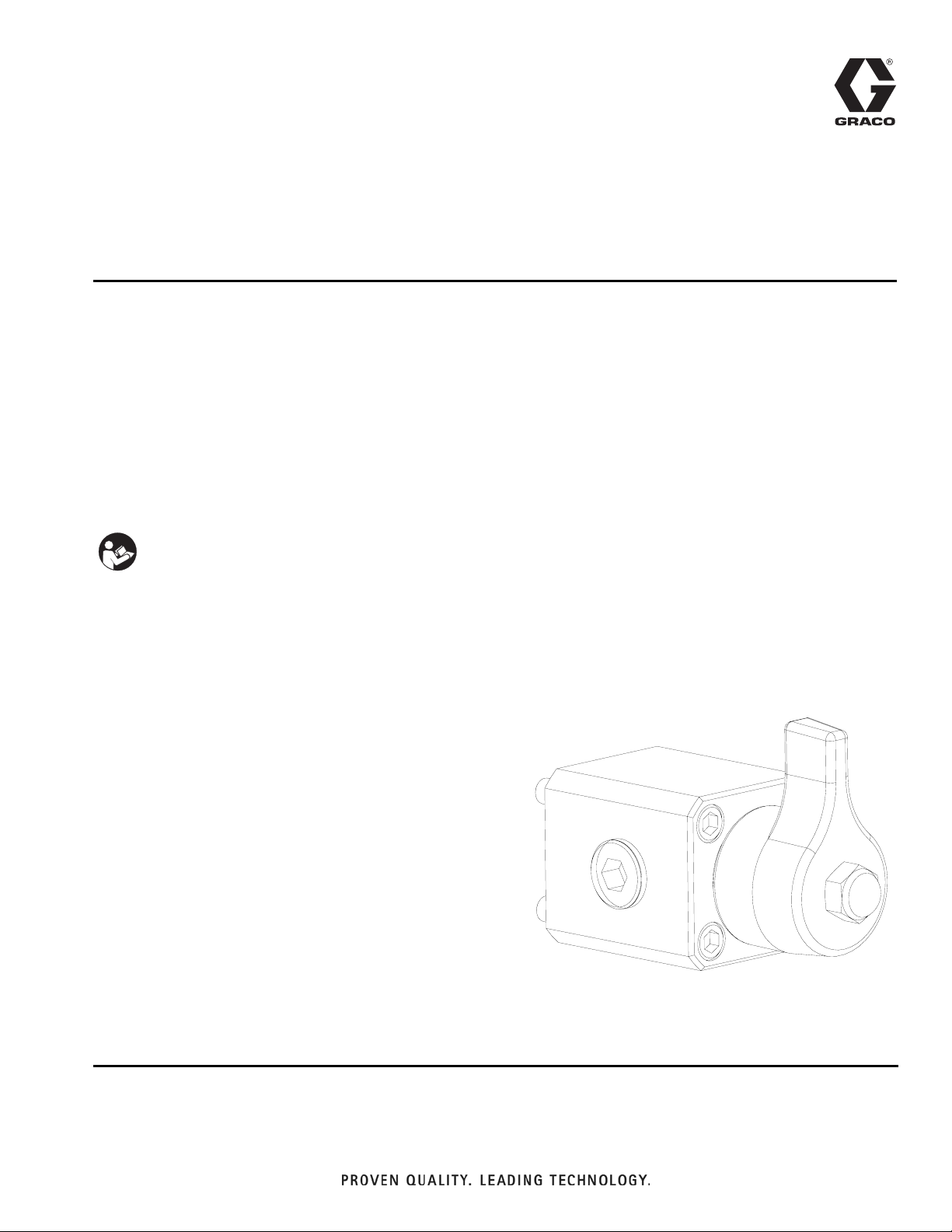
Instructions-Parts
High Flow Severe
Duty Shutoff Check
Valve
For recirculation valves, shutoff check valves, or outlet shutoff check valves on XM
plural-component sprayers.
Part No. 255278
Complete high flow severe duty shutoff check valve assembly
7250 psi (50 MPa, 500 bar) Maximum Working Pressure
160°F (71°C) Maximum Fluid Temperature
Important Safety Instructions
Read all warnings and instructions in this manual
and manuals 312359 and 313289. Save these
instructions.
313343A
Page 2

Related Manuals
Contents
Related Manuals . . . . . . . . . . . . . . . . . . . . . . . . . . . 2
Warnings . . . . . . . . . . . . . . . . . . . . . . . . . . . . . . . . . 3
Overview . . . . . . . . . . . . . . . . . . . . . . . . . . . . . . . . . . 4
Setup . . . . . . . . . . . . . . . . . . . . . . . . . . . . . . . . . . . . . 6
Repair . . . . . . . . . . . . . . . . . . . . . . . . . . . . . . . . . . . . 6
Parts . . . . . . . . . . . . . . . . . . . . . . . . . . . . . . . . . . . . . 7
Troubleshooting . . . . . . . . . . . . . . . . . . . . . . . . . . . . 8
Repair Kit . . . . . . . . . . . . . . . . . . . . . . . . . . . . . . . . . 8
Accessories . . . . . . . . . . . . . . . . . . . . . . . . . . . . . . . 8
Technical Data . . . . . . . . . . . . . . . . . . . . . . . . . . . . . 9
Mounting Dimensions . . . . . . . . . . . . . . . . . . . . . . . 9
Graco Standard Warranty . . . . . . . . . . . . . . . . . . . 10
Graco Information . . . . . . . . . . . . . . . . . . . . . . . . . 10
Related Manuals
Component Manuals in U.S. English:
Manual Description
312359 XM Operation
313289 XM Repair
313292 XM OEM, Instructions-Parts
313342 Dosing Valve, Instructions-Parts
312749
XM Mix Manifold Kits
Instructions-Parts
2 313343A
Page 3
Warnings
Warnings
The following warnings are for the setup, use, grounding, maintenance, and repair of this equipment. The exclamation point symbol alerts you to a general warning and the hazard symbol refers to procedure-specific risk. Refer back
to these warnings. Additional, product-specific warnings may be found throughout the body of this manual where
applicable.
WARNING
WARNINGWARNINGWARNING
FIRE AND EXPLOSION HAZARD
Flammable fumes, such as solvent and paint fumes, in work area can ignite or explode. To help prevent
fire and explosion:
• Use equipment only in well ventilated area.
• Eliminate all ignition sources; such as pilot lights, cigarettes, portable electric lamps, and plastic drop
cloths (potential static arc).
• Keep work area free of debris, including solvent, rags and gasoline.
• Do not plug or unplug power cords, or turn power or light switches on or off when flammable fumes
are present.
• Ground all equipment in the work area. See Grounding instructions.
• Use only grounded hoses.
• Hold gun firmly to side of grounded pail when triggering into pail.
• If there is static sparking or you feel a shock, stop operation immediately. Do not use equipment
until you identify and correct the problem.
• Keep a working fire extinguisher in the work area.
PRESSURIZED EQUIPMENT HAZARD
Fluid from the gun/dispense valve, leaks, or ruptured components can splash in the eyes or on skin and
cause serious injury.
• Follow Pressure Relief Procedure in this manual, when you stop spraying and before cleaning,
checking, or servicing equipment.
• Tighten all fluid connections before operating the equipment.
• Check hoses, tubes, and couplings daily. Replace worn or damaged parts immediately.
TOXIC FLUID OR FUMES HAZARD
Toxic fluids or fumes can cause serious injury or death if splashed in the eyes or on skin, inhaled, or
swallowed.
• Read MSDS’s to know the specific hazards of the fluids you are using.
• Store hazardous fluid in approved containers, and dispose of it according to applicable guidelines.
• Always wear impervious gloves when spraying or cleaning equipment.
PERSONAL PROTECTIVE EQUIPMENT
You must wear appropriate protective equipment when operating, servicing, or when in the operating
area of the equipment to help protect you from serious injury, including eye injury, inhalation of toxic
fumes, burns, and hearing loss. This equipment includes but is not limited to:
• Protective eyewear
• Clothing and respirator as recommended by the fluid and solvent manufacturer
•Gloves
• Hearing protection
313343A 3
Page 4

Overview
Overview
The high flow severe duty shutoff check valve is a valve
that acts as a spring loaded one-way check valve when
the valve is in the open position. When the handle is
turned to the closed position, the ball is held against the
seat closing flow in either direction. The valve can be
manifold mounted with four screws and an o-ring face
seal on the inlet, or it can be plumbed in place with 1/2
in. npt (f) threads on the inlet and two outlets.
Flow Direction
NOTE:
It is recommended that this valve be used in the fully
open and fully closed positions. To control the flow rate
on a circulation line, use adjustable restriction valve
222200. See Accessories on page 8.
Flow Direction
F
IG. 1: Cutaway View
4 313343A
Page 5

Overview
313343A 5
Page 6

Setup
Setup
Reference parts illustration on page 7.
1. Mount the valve in place with two outlet ports
pointed in the desired direction using o-ring (14) and
four screws (11).
2. Plug the un-used outlet port with plug (15). Use
thread tape or sealant on the npt threads.
3. Use handle (12) to close the valve stem (8) clockwise. Position handle (12) to point in the direction
you want to show as “closed”.
4. Secure handle (12) in place on stem (8) with crown
nut (11).
Repair
7. Clean and inspect parts for wear and damage.
Replace damaged parts from repair kit 256239.
Assemble
Reference parts illustration on page 7.
1. Install o-ring (9) in groove of check valve housing
(10).
NOTICE
Do not install seal (6) and spacer (7) at this time to
prevent damage to seal.
2. Start to thread stem (8) by hand into bottom of cartridge (10). Place handle (12) on stem (8) and turn
counter-clockwise to fully thread stem (8) through
top of cartridge (10) to full open position.
3. Insert spacer (7). Use plastic tool (110) and hammer
(not provided) to install seal (6) with lips facing away
from spacer (7) on to stem (8) until it stops against
spacer (7).
Disassemble
Reference parts illustration on page 7.
1. Relieve upstream and downstream pressure. See
operation manual 312359 for Pressure Relief Pro-
cedure. Leave stem (8) in open position.
2. Clamp housing (1) in a vice. Remove nut (13) and
handle (12) from top check valve housing (10).
3. Remove cartridge assembly (10) from housing (1).
4. Remove ball (4), and spring (5).
5. Use plastic tool (110) provided in repair kit 256239
to remove seat (3) and seal (2).
NOTE:
If valve housing (10) is still mounted on a machine, use
a 90° hex key to grab under seat (3) and remove from
housing (1).
6. Place handle (12) upside down on stem (8). Turn
clockwise and remove stem (8) from cartridge (10).
The seal (6) and spacer (7) will come out with the
stem. Remove seal (6) and spacer (7) from stem
(8).
4. Place cartridge (10) in vice with bottom facing
upward. Place spring (5) and ball (4) on stem (8).
Firmly press seal (2) over lip of cartridge until it
snaps into place and holds all the parts in place.
5. Apply blue thread lock, from repair kit 256239, on
cartridge (10) external threads and insert cartridge
assembly into check valve housing (1).
6. Place housing (1) in vice and torque to 125 ft-lbs.
7. Mount valve and position handle as described in
Setup.
6 313343A
Page 7

Parts
255278, Complete Shutoff Check Valve Shown
11
14
3
2 4
Parts
2
3
3
6
7
8
9
3
2
15
1
Torque to 125 ft-lbs. (170 N•m)
2
Apply blue threadlock.
3
Apply lithium grease.
4
Torque to 16-20 ft-lbs. (22-27 N•m)
1
11
2 4
3
4
Ref. Part Description Qty.
1 15J594 HOUSING, check valve 1
2*◆ 15K692 SEAL, retainer, acetal 1
3* 15A968 SEAT, footvalve, carbide 1
4* 116166 BALL, carbide 1
5* 15M530 SPRING 1
6*◆ 15M529 SEAL, u-cup; UHMWPE 1
7* 15M189 SPACER, backup, seal 1
8* 15K347 STEM 1
9*◆ 121138 O-RING; PTFE 1
10* 15K199 HOUSING, top, check valve 1
11 121295 SCREW, cap, shcs; 5/16-18 x 2.5
in.
12 15R381 HANDLE, black 1
13 117623 NUT, cap (3/8-16) 1
14 121139 O-RING; PTFE 1
15 100361 PLUG, pipe; 1/2 npt 1
5
10
1
12
13
4
* Included in shutoff check valve cartridge 255747.
◆ Included in shutoff check valve repair kit 256239
(purchase separately). See page 8 for parts included
in kit.
313343A 7
Page 8

Troubleshooting
Troubleshooting
Problem Cause Solution
Handle is hard to turn under pressure.
Cartridge (10) is not tightened completely into housing (1).
Torque cartridge (10) to 125 ft-lbs.
(170 N•m).
Repair Kit
256239, Shutoff Check Valve Repair Kit
See parts illustration on page 7.
Ref Part Description Qty.
2 15K692 SEAL, retainer, carbide 1
615M529SEAL 1
9 121138 O-RING 1
110† 15T630 TOOL, u-cup and manifold 1
111† 113500 ADHESIVE, anaerobic 1
† Not shown.
Accessories
Handles
Part Description Qty.
247789 HANDLE, blue 1
15R380 HANDLE, green 1
247788 HANDLE, red 1
15R529, Fluid Inlet Block
Used on XM outlet to mount high flow severe duty
shut-off check valve when mix manifold is remote. See
manual 312749 for parts.
256980, XM Remote Mix Manifold
Conversion Kit
See manual 312749.
222200, Restriction Valve
Used to control flow rate in circulation lines. See manual
307892.
8 313343A
Page 9

Technical Data
Technical Data
Maximum Fluid Working Pressure . . . . . . . . . . . . . . . . . . 7250 psi (50 MPa, 500 bar)
Maximum Fluid Temperature . . . . . . . . . . . . . . . . . . . . . . 160°F (71°C)
Check Valve Housing Fluid Ports . . . . . . . . . . . . . . . . . . . 1/2 in. npt
Wetted Parts. . . . . . . . . . . . . . . . . . . . . . . . . . . . . . . . . . . carbide ball, carbide seat, sst stem, nickel plated steel,
PTFE o-rings, UHMWPE u-cup, acetal end cup seal.
Full turns from closed to open position. . . . . . . . . . . . . . . 1.5 turns
Loctite® is a registered trademark of the Loctite Corporation.
Mounting Dimensions
1.44 in. (36.6 mm)
1.44 in. (36.6 mm)
0.72 in. (18.3 mm)
2.1 in. (53.9 mm)
NOTE:
For manifold mounting this valve, the o-ring
face groove must be duplicated on the mating
surface.
2.1 in. (53.9 mm)
0.72 in. (18.3 mm)
.053 in. (1.346 mm)
2.44 in.
(61.96 mm)
1.055 in.
(25.5 mm.)
313343A 9
Page 10

Graco Standard Warranty
Graco warrants all equipment referenced in this document which is manufactured by Graco and bearing its name to be free from defects in
material and workmanship on the date of sale to the original purchaser for use. With the exception of any special, extended, or limited warranty
published by Graco, Graco will, for a period of twelve months from the date of sale, repair or replace any part of the equipment determined by
Graco to be defective. This warranty applies only when the equipment is installed, operated and maintained in accordance with Graco’s written
recommendations.
This warranty does not cover, and Graco shall not be liable for general wear and tear, or any malfunction, damage or wear caused by faulty
installation, misapplication, abrasion, corrosion, inadequate or improper maintenance, negligence, accident, tampering, or substitution of
non-Graco component parts. Nor shall Graco be liable for malfunction, damage or wear caused by the incompatibility of Graco equipment with
structures, accessories, equipment or materials not supplied by Graco, or the improper design, manufacture, installation, operation or
maintenance of structures, accessories, equipment or materials not supplied by Graco.
This warranty is conditioned upon the prepaid return of the equipment claimed to be defective to an authorized Graco distributor for verification of
the claimed defect. If the claimed defect is verified, Graco will repair or replace free of charge any defective parts. The equipment will be returned
to the original purchaser transportation prepaid. If inspection of the equipment does not disclose any defect in material or workmanship, repairs will
be made at a reasonable charge, which charges may include the costs of parts, labor, and transportation.
THIS WARRANTY IS EXCLUSIVE, AND IS IN LIEU OF ANY OTHER WARRANTIES, EXPRESS OR IMPLIED, INCLUDING BUT NOT LIMITED
TO WARRANTY OF MERCHANTABILITY OR WARRANTY OF FITNESS FOR A PARTICULAR PURPOSE.
Graco’s sole obligation and buyer’s sole remedy for any breach of warranty shall be as set forth above. The buyer agrees that no other remedy
(including, but not limited to, incidental or consequential damages for lost profits, lost sales, injury to person or property, or any other incidental or
consequential loss) shall be available. Any action for breach of warranty must be brought within two (2) years of the date of sale.
GRACO MAKES NO WARRANTY, AND DISCLAIMS ALL IMPLIED WARRANTIES OF MERCHANTABILITY AND FITNESS FOR A
PARTICULAR PURPOSE, IN CONNECTION WITH ACCESSORIES, EQUIPMENT, MATERIALS OR COMPONENTS SOLD BUT NOT
MANUFACTURED BY GRACO. These items sold, but not manufactured by Graco (such as electric motors, switches, hose, etc.), are subject to
the warranty, if any, of their manufacturer. Graco will provide purchaser with reasonable assistance in making any claim for breach of these
warranties.
In no event will Graco be liable for indirect, incidental, special or consequential damages resulting from Graco supplying equipment hereunder, or
the furnishing, performance, or use of any products or other goods sold hereto, whether due to a breach of contract, breach of warranty, the
negligence of Graco, or otherwise.
FOR GRACO CANADA CUSTOMERS
The Parties acknowledge that they have required that the present document, as well as all documents, notices and legal proceedings entered into,
given or instituted pursuant hereto or relating directly or indirectly hereto, be drawn up in English. Les parties reconnaissent avoir convenu que la
rédaction du présente document sera en Anglais, ainsi que tous documents, avis et procédures judiciaires exécutés, donnés ou intentés, à la suite
de ou en rapport, directement ou indirectement, avec les procédures concernées.
Graco Information
For the latest information about Graco products, visit www.graco.com.
TO PLACE AN ORDER, contact your Graco distributor or call to identify the nearest distributor.
Phone: 612-623-6921 or Toll Free: 1-800-328-0211 Fax: 612-378-3505
All written and visual data contained in this document reflects the latest product information available at the time of publication.
Graco reserves the right to make changes at any time without notice.
This manual contains English. MM 313343
Graco Headquarters: Minneapolis
International Offices: Belgium, China, Japan, Korea
GRACO INC. P.O. BOX 1441 MINNEAPOLIS, MN 55440-1441
Copyright 2009, Graco Inc. is registered to ISO 9001
www.graco.com
 Loading...