

Page 1
INSTRUCTIONS
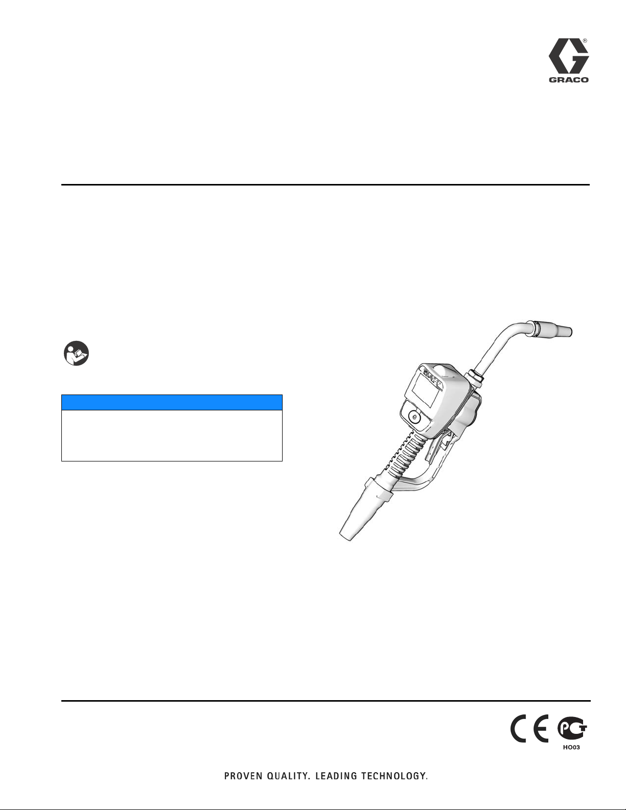
SDM5 & SDM15 (Manual);
SDP5 & SDP15 (Preset)
312865G
Meters
For metered dispense of oils and 50:50 antifreeze/water mix fluids. For professional use
only.
Not for use in explosive atmospheres.
Maximum Working Pressure: 1500 psi (10 MPa, 103 bar)
Maximum Working Pressure (50:50 antifreeze/water mix): 900 psi (6.2 MPa, 62 bar)
Maximum Flow Rate:14 gpm (53 lpm)
List of Models page 2
Preset Meter shown
Important Safety Instructions
Read all warnings and instructions in this
manual. Save these instructions.
NOTICE
This dispense valve is designed to dispense
petroleum-based lubricants and antifreeze only.
Do not dispense windshield washer solvent with
this dispense valve.
ENG
ti11821
US Patent No: D594,490S
India Patent No: 219652
Korea Patent No: 30-555779
Taiwan Patent No: D130836
Page 2
Models
Models
SDM5 Manual Dispense Electronic Meters
Model
Number Swivel Extension Description Nozzle Fluid Type
255348 1/2” npt(f) Flexible Extension Automatic, non-drip, quick close Oil
255349 1/2” npt(f) Gear Lube Extension None-drip, quick close Gear Lube
255350 1/2” npt(f) Rigid Extension Automatic, non-drip, quick close Oil
255802 1/2” npt(f) Rigid Extension Automatic, non-drip, quick close Anti-freeze
255803 1/2” npt(f) Flexible Extension Automatic, non-drip, quick close Anti-freeze
SDM15 Manual Dispense Electronic Meters
Model
Number Swivel Extension Description Nozzle Fluid Type
255800 3/4” npt(f) Rigid Extension Automatic, non-drip, quick close Oil
255801 3/4” npt(f) Flexible Extension Automatic, non-drip, quick close Oil
255836 1/2” npt(f) Rigid Extension Automatic, non-drip, quick close Oil
255837 1/2 npt(f) Flexible Extension Automatic, non-drip, quick close Oil
SDP5 Preset Dispense Electronic Meters
Model
Number Swivel Extension Description Nozzle Fluid Type
255200 1/2” npt(f) Rigid Extension Automatic, non-drip, quick close Oil
255351 1/2” npt(f) Flexible Extension Automatic, Non-drip, quick close Oil
255352 1/2” npt(f) Gear Lube Extension Non-drip, quick close Gear Lube
255355 1/2” npt(f) Rigid Extension Automatic, non-drip, quick close Anti-freeze
255356 1/2” npt(f) Flexible Extension Automatic, non-drip, quick close Anti-freeze
2 312865G
Page 3

SDP15 Preset Dispense Electronic Meters
Model
Number Swivel Extension Description Nozzle Fluid Type
255353 3/4” npt(f) Rigid Extension Automatic, non-drip, quick close Oil
255354 3/4” npt(f) Flexible Extension Automatic, non-drip, quick close Oil
256838 1/2” npt(f) Rigid Extension Automatic, non-drip, quick close OIl
256839 1/2” npt(f) Flexible Extension Automatic, non-drip, quick close Oil
Models
312865G 3
Page 4
Warnings
Warnings
The following warnings are for the setup, use, grounding, maintenance, and repair of this equipment. The exclamation point symbol alerts you to a general warning and the hazard symbol refers to procedure-specific risk. Refer back
to these warnings. Additional, product-specific warnings may be found throughout the body of this manual where
applicable.
WARNING
SKIN INJECTION HAZARD
High-pressure fluid from dispense valve, hose leaks, or ruptured components will pierce skin. This may
look like just a cut, but it is a serious injury that can result in amputation. Get immediate surgical
treatment.
• Do not point dispense valve at anyone or at any part of the body.
• Do not put your hand over the end of the dispense nozzle.
• Do not stop or deflect leaks with your hand, body, glove, or rag.
• Follow Pressure Relief Procedure in this manual, when you stop spraying and before cleaning,
checking, or servicing equipment.
EQUIPMENT MISUSE HAZARD
Misuse can cause death or serious injury.
• Do not operate the unit when fatigued or under the influence of drugs or alcohol.
• Do not exceed the maximum working pressure or temperature rating of the lowest rated system
component. See Technical Data in all equipment manuals.
• Use fluids and solvents that are compatible with equipment wetted parts. See Technical Data in all
equipment manuals. Read fluid and solvent manufacturer’s warnings. For complete information
about your material, request MSDS forms from distributor or retailer.
• Check equipment daily. Repair or replace worn or damaged parts immediately with genuine manufacturer’s replacement parts only.
• Do not alter or modify equipment.
• Use equipment only for its intended purpose. Call your distributor for information.
• Route hoses and cables away from traffic areas, sharp edges, moving parts, and hot surfaces.
• Do not kink or over bend hoses or use hoses to pull equipment.
• Keep children and animals away from work area.
• Comply with all applicable safety regulations.
BATTERY SAFETY
The battery may leak, explode, cause burns, or cause an explosion if mishandled:
• You must use the battery type specified for use with the equipment.
• Sparking can occur when changing batteries. Only replace the battery in a non-hazardous location,
away from flammable fluids or fumes.
• Handle and dispose of battery properly - do not short circuit, charge, force over discharge, disassemble, crush, penetrate, incinerate, or heat the battery to a temperature exceeding 185° F (85° C).
4 312865G
Page 5

Warnings
WARNING
FIRE AND EXPLOSION HAZARD
When flammable fluids are present in the work area, such as gasoline and windshield wiper fluid, be
aware that flammable fumes can ignite or explode. To help prevent fire and explosion:
• Use equipment only in well ventilated area.
• Eliminate all ignition sources, such as cigarettes and portable electric lamps.
• Keep work area free of debris, including rags and spilled or open containers of solvent and gasoline.
• Do not plug or unplug power cords or turn lights on or off when flammable fumes are present.
• Ground all equipment in the work area.
• Use only grounded hoses.
• If there is static sparking or you feel a shock, stop operation immediately. Do not use equipment
until you identify and correct the problem.
• Keep a working fire extinguisher in the work area.
312865G 5
Page 6
Installation
Installation
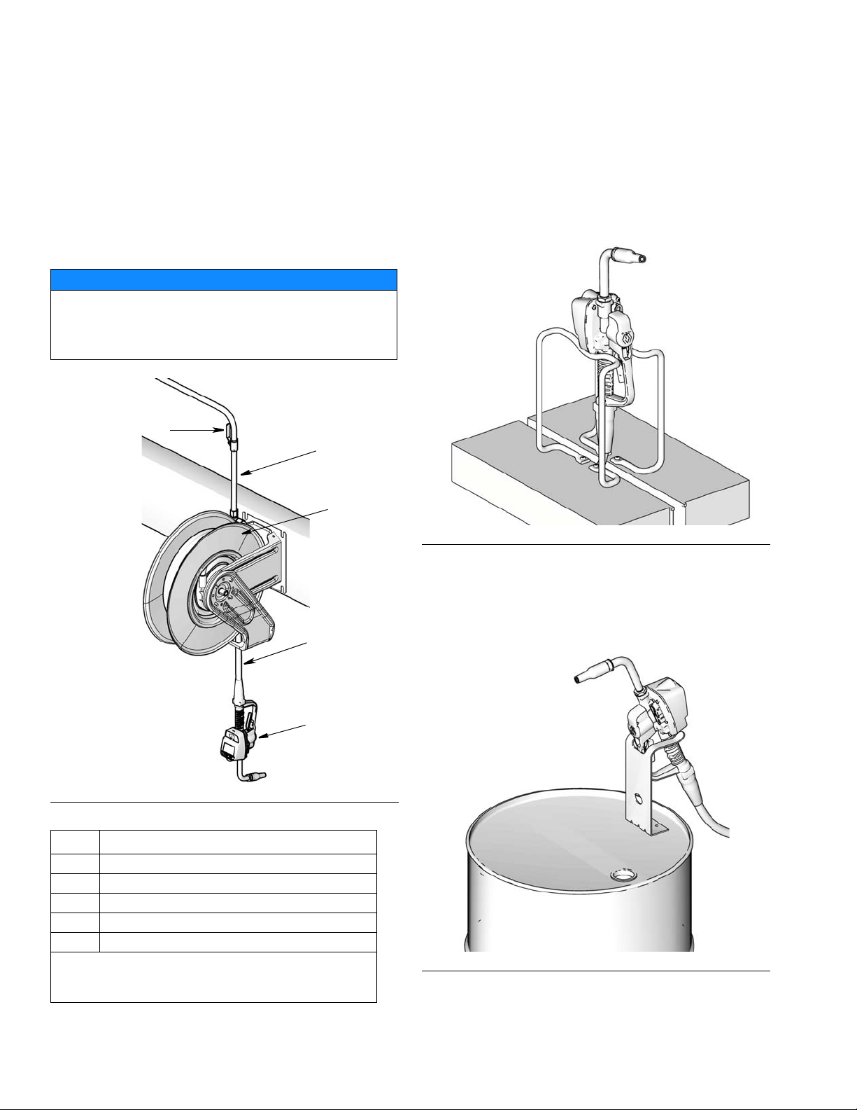
Typical Installations (FIG. 1)
The typical installation shown in FIG. 1 is only a guide. It
is not a complete system design. Contact your Graco
distributor for assistance in designing a system to suit
your needs.
NOTICE
The dispense valve is not designed for in-line
installation. Do not install with a shutoff valve on the
outlet side of the meter. Such installation could result in
damage to the meter housing cover.
B
D
E
Mounting Bracket (FIG. 2)
Mounting Bracket Kit 249440 is available for resting the
dispense valve on a console.
ti11822
FIG. 2
C
A
ti11010a
F
IG. 1
ITEM DESCRIPTION
A Electronic metered dispense valve
B Fluid shut-off valve
CHose
D Hose reel fluid inlet hose
E Hose reel
A Thermal Relief Kit (not shown) is required. The kit
required will vary by pump selected. See Parts, page 40 for
a list of available kits.
Drum Mount Bracket (FIG. 3)
Mounting Bracket 15B750 is available for resting the
dispense valve on a drum.
ti11823
IG. 3
F
6 312865G
Page 7

Installation
Pressure Relief Procedure
This equipment will stay pressurized until the pressure
has been manually relieved. To reduce the risk of
serious injury from pressurized fluid, accidental spray
from the dispense valve or splashing fluid, follow this
Pressure Relief Procedure when ever you:
• Are instructed to relieve pressure.
• Check, clean or service any system equipment.
• Install or clean fluid nozzles or filter.
1. Turn off power supply to the pump or close
upstream ball valve.
2. Trigger the dispense valve into a waste container to
relieve pressure.
3. Open any bleed-type master air valves and fluid
drain valves in the system.
4. Leave the drain valve open until you are ready to
pressurize the system.
Air compressor: Follow manufacturer’s
recommendations.
Fluid supply container: Follow local code.
To maintain grounding continuity when flushing or
relieving pressure: hold a metal part of the dispense
valve firmly to the side of a grounded metal pail, then
trigger the valve.
Pre-Installation Procedure
1. Relieve pressure, page 7.
2. Close the shut-off valve (B, F
3. Ground the hose and reel or console, page 7. Leave
at least two threads bare when using PTFE tape.
The bare threads ensure a ground is maintained.
IG. 1).
Installation Procedure
Grounding
FIRE HAZARD: Conductive metal surfaces on the
meter must not make contact with any positively
charged metal surface, including (but not limited to),
the starter solenoid terminal, alternator terminal or
battery terminal. Such contact could cause electrical
arcing and a fire.
The equipment must be grounded. Grounding reduces
the risk of static and electric shock by providing an
escape wire for the electrical current due to static build
up or in the event of a short circuit.
Pump: Follow manufacturer’s recommendations.
Air and fluid hoses: Only use electrically conductive
hoses. Check electrical resistance of hoses. If total
resistance to ground exceeds 29 megohms, replace
hose immediately.
NOTICE
• If this is a new installation or if the fluid lines are
contaminated, flush the lines before you install the
metered valve. Contaminated lines could cause the
valve to leak.
• Never dispense compressed air with meter. Doing
so will damage meter.
Flushing
If this is an existing installation, go to Installing Meter
section, page 8. The following procedure, Steps 1-5 are
the Flushing Procedure.
1. Close the fluid shut-off valve (B, F
each dispense position.
2. Make sure:
• main fluid outlet valve at the pump is closed,
• air pressure to the pump motor is adjusted,
and
• air valve is open.
IG. 1, page 6) at
312865G 7
Page 8
Installation
3. Slowly open the main fluid valve.
a. Place the hose end (with no dispense valve
connected) into a container for waste oil.
b. Secure the hose in the container so it will not
come out during flushing.
c. If you have multiple dispense positions, first
flush the dispense position farthest from the
pump and work your way toward the pump.
4. Slowly open the shut-off valve (B) at the dispense
position. Flush out a sufficient amount of oil to
ensure that the entire system is clean; then close
the valve.
5. Repeat Step 4 at all other positions.
Installing Meter (FIG. 4
)
1. Relieve pressure, page 7.
a
31
32
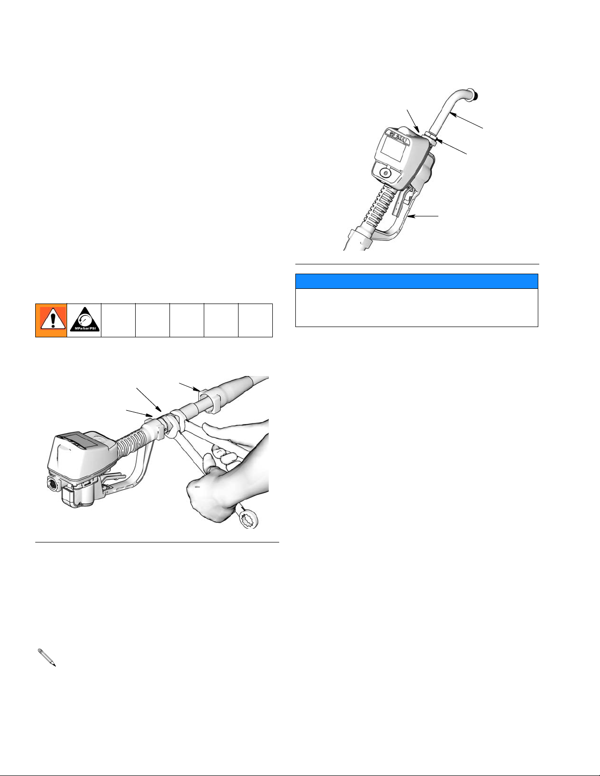
Installing Tube Extension (FIG. 5)
b
20
a
c
ti10615A
IG. 5
F
NOTICE
Do not use PTFE tape or thread sealant on threads of
extension tube (20). This could cause the fitting to
leak.
1.
a. Loosen nut (a) until it is completely off tube
threads.
b. Thread extension (20) into housing (b) until it
bottoms out.
c. Align extension (20) with meter housing and
handle (c).
d. Firmly tighten nut (a).
ti10983a
FIG. 4
2. Slide the swivel boot (32) back, over the hose, small
end first, to access the swivel fitting (a).
3. Apply thread sealant to the male threads of the hose
fitting. Thread the hose fitting into the meter swivel
(31). Use two wrenches to tighten securely (F
IG. 4).
Make sure you let the sealant cure to the manufacturer’s recommendations before circulating fluid
through the system.
8 312865G
Page 9
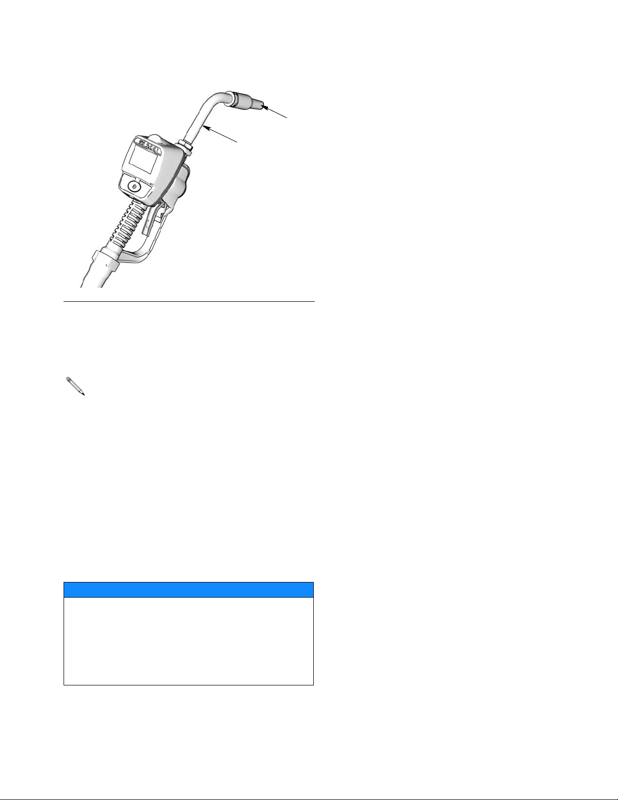
Installing Nozzle (FIG. 6)
20
ti10615A
F
IG. 6
1.
a. Thread new nozzle (33) onto extension (20).
b. With an open-end adjustable wrench on flats of
nozzle bushing, tighten firmly.
Installation
33
• Only tighten nozzle with wrench on flats of the
nozzle bushing.
• Do not disassemble the bushing from
nozzle. Disassembly will affect performance of
the nozzle.
2. Open automatic twist lock nozzle and all fluid
shut-off valves. Start pump to pressurize system.
See Operation Screens, Dispensing in either the
Manual or Preset Mode instructions beginning on
page 19 for complete meter operation information.
3. To ensure dispensing accuracy, purge all air from
the fluid lines and dispense valve before you use it.
4. Set the system flow to the desired flow rate.
NOTICE
Do not trigger meter when nozzle is closed. Fluid
will build up behind the nozzle, leak from the nozzle,
and unexpectedly be expelled when the nozzle is
opened. If you do accidentally trigger the meter with
the nozzle closed, point the nozzle into a waste
bucket and open the nozzle to relieve pressure and
expel the built up fluid.
312865G 9
Page 10
Meter Overview
Meter Overview
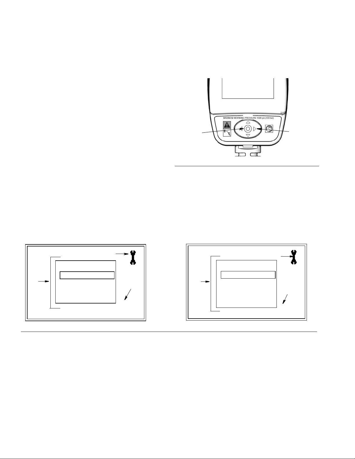
Navigation and Modes
ti11824
F
IG. 7
5-Way Menu
Navigation Button
Meter Display
Adjusting Screen Contrast using ARROWS
On the Setup Home Screen (page 11), use the LEFT
and RIGHT ARROWS to adjust the screen contrast.
• Darken the Screen: Press the RIGHT ARROW
multiple times.
• Brighten the Screen: Press the LEFT ARROW
multiple times.
Asleep/Awake Mode
• Asleep: Battery-saving mode. The display goes
blank after 2 minutes of inactivity during normal
operation. Unit continues to keep track of amount
dispensed while the display is asleep.
• Awake: Display comes awake from sleep mode
when you press any ARROW or the ENTER button
or when you squeeze the trigger to dispense fluid.
Locking and Unlocking Trigger
The Preset Meters only, include a locking trigger feature
that allows the user to lock the trigger in the dispense
position as shown in F
squeeze the trigger to the handle.
Preset Meters Only
IG. 8. To release the lock, firmly
5-Way Menu Navigation Button (FIG. 7)
• Includes 4 direction ARROWS (UP, DOWN, LEFT,
RIGHT) and a center, ENTER button.
• Pressing the direction ARROWS allows user to
easily scroll through menus. To select/store your
selection, you must press the center, ENTER
button.
• Pressing and holding a direction ARROW down
allows user to scroll through menus quickly.
FIG. 8
10 312865G
Unlocked
Locked
Page 11
Setup Mode Screens
Setup Mode Screens
If you are in Operation Mode you must be on the Home Screen shown in FIG. 10, to access the Setup Mode Screens.
(A complete description of the Home Screen is provided on page 18).
To display the Home Screen:
1. Wake up the meter by pressing any button on the key pad.
2. When an operation mode screen displays (such as
MOBIL
5W-20
1
the one shown in F
a. Use the RIGHT ARROW to move the curser
over the House icon (a).
IG. 9):
F
IG. 9
Manual Meters
FIG. 10
10.56
MOBIL
MANUAL
TOTALS
5W-20
1
QTS
b. Press center, ENTER button to display the
Home Screen (F
a
ti12179a
Preset Meters
IG. 10).
MOBIL
5W-20
1
MANUAL
PRESET
TOTALS
ti12175a
ti12184a
312865G 11
Page 12
Setup Mode Screens
P
Main Setup Screen (FIG. 12)
All Meters
The Main Setup Screen is the first screen displayed
when you enter the Setup Mode. This screen displays a
list of the available Setup Screens and also includes a
link back to the Home Screen.
Manual Meters Screens:
• UNITS/LIMIT
•CALIBRATE
• BANNER
•LANGUAGE
•HOME
Preset Meters include all the Manual Meter’s Setup
Screens and also a PRESET screen.
• UNITS/LIMIT
•CALIBRATE
• PRESET
• BANNER
•LANGUAGE
•HOME
Displaying Setup Screen from an Operation
Mode Screen
(b)
ti11824a
F
IG. 11
1. Hold down the RIGHT ARROW (a) only, for a few
seconds (F
2. Then at the same time, also press the center,
ENTER button (b) (F
until the Main Setup Screen shown in F
plays.
IG. 11).
IG. 11). Hold both buttons down
(a)
IG. 12 dis-
Manual Meters
A
UNITS/LIMIT
CALIBRATE
B
FIG. 12
Main Screen Features (F
A. Screen Identifier Icon: Wrench icon displays in the
upper right corner when user is on the Main Screen of
the Setup screens.
BANNER
LANGUAGE
HOME
IG. 12)
1
1.23.45
ti12177a
reset Meters
A
UNITS/LIMIT
CALIBRATE
B
PRESET
BANNER
1
LANGUAGE
HOME
B. Setup Screens: Screens available to user.
1. Use UP or DOWN ARROWS to select a screen from
the list.
2. Press center, ENTER button to confirm selection.
Selected screen displays.
1. Software Version Number: Reference number. You
may be asked to provide this number when contacting
Graco for technical support.
1.23.45
ti12186a
12 312865G
Page 13
Units/Limit Screen (FIG. 13)
For All Meters
Sets the units of measurement to pints, quarts, liters, or gallons.
Setup Mode Screens
Manual Meters
UNITS = QTS
QTS
F
IG. 13
Units/Limit Screen Features (F
E
C
D
IG. 13)
All meters include C - E
C. Units Mode: Displays measurement unit that was
selected using the Set Measurement Units
button (E).
D. Wrench Icon: Returns user to Main Setup Screen.
E. Set Measurement Units button/field: Sets unit of
measurement as pint, quart, gallon or liter.
To change/set the Unit of Measurement:
Preset Meters
UNITS = QTS
G
MANUAL LIMIT = 5.0
E
QTS
F
5.0
D
C
ti12191a
Preset meters also include F - G
F. Set Manual Dispense Limit field: Sets maximum
quantity of fluid that can be dispensed in Manual Mode.
To change/set the Manual Dispense Limit:
1. Use RIGHT ARROW to move curser to Manual Dispense Limit field (F).
2. Use UP or DOWN ARROWS to increase and
decrease displayed amount.
1. Use LEFT or RIGHT ARROW to move curser to the
Set Measurement field (E).
3. When amount you want to use is shown in field,
press center, ENTER button to confirm amount.
Confirmed amount displays on screen (G).
2. Use UP or DOWN ARROWS to display measurement unit choices: PTS, QTS, L, GAL.
4. When you have finished making changes, use the
RIGHT ARROW button to move curser over Wrench
3. Press center, ENTER button to confirm selection.
Selected measurement unit is displayed on screen
(C).
4. When you are finished making changes, use the
RIGHT ARROW to move curser over Wrench icon.
5. Press center, ENTER button to return to Main Setup
Screen.
icon.
5. Press center, ENTER button to return to Main Setup
Screen.
G. Manual Limit Confirmation: Displays maximum
quantity of fluid that can be manually dispensed at one
time. Amount is assigned on the task bar Set Manual
Dispense Limit field (F). Preset dispense amounts are
not affected by the manual dispense limit you set.
312865G 13
Page 14
Setup Mode Screens
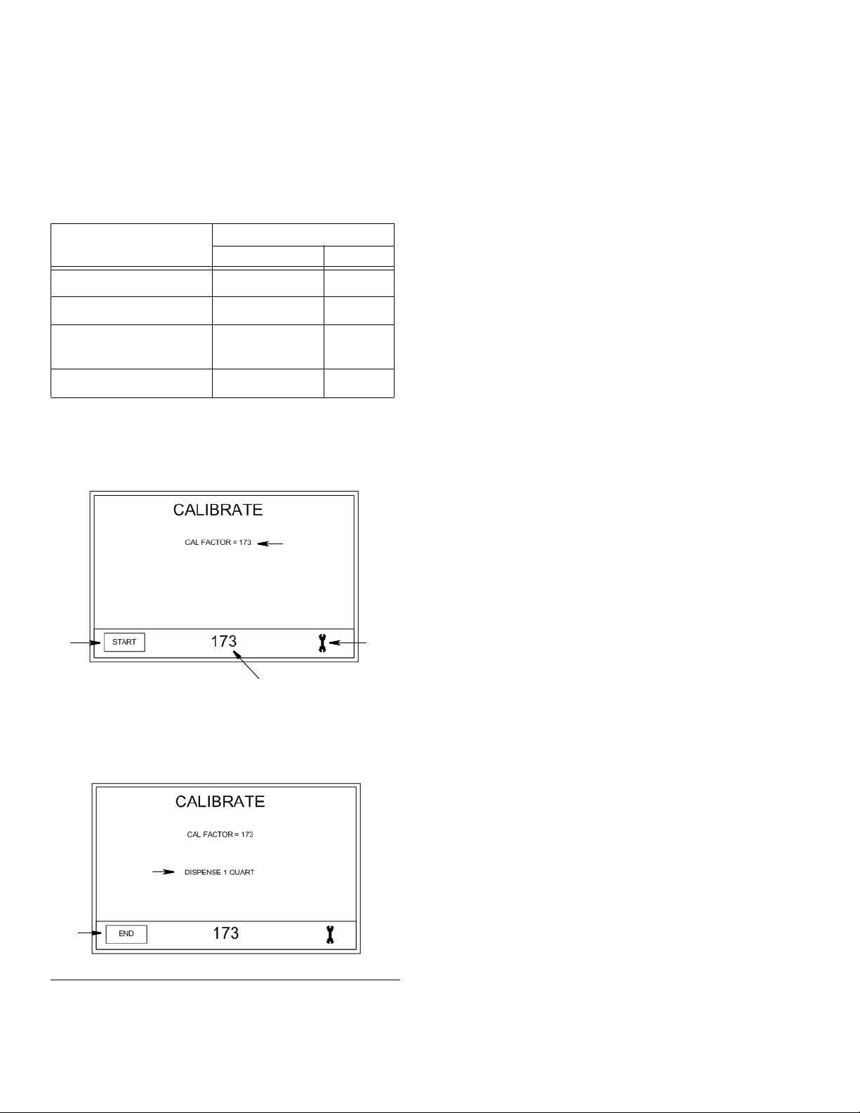
Calibrate Screen (FIG. 14)
For All Meters
Recalibrates the meter for different fluids.
Table 1. Calibration Factors
Calibration Number
Fluids
Oil (10W - 30)
Gear Lube
Automatic
Quarts Liters
173 183
173 183
167 176
Transmission Fluid
Antifreeze
• Calibration factors at 70°F (21°C) at 2.0 gpm (7.6 lpm).
• Calibration number may vary slightly due to temperature
or flow rate.
159 168
Calibrate Screen 1
J
All meters include D - M
D. Wrench Icon: Returns user to Main Screen.
J. Calibration Factor: Displays amount operator
dispensed during meter calibration.
K. Preset Calibration Factor: Preset calibration
amount displays.
Adjusting the Preset Calibration Factor:
1. Use your LEFT or RIGHT ARROW to move the
curser to the Calibration Factor Field (K) .
2. Use the UP or DOWN ARROW to manually adjust
the Preset Calibration Factor up or down (this can
only be done on Calibrate Screen 1 (F
IG. 14).
3. Press center, ENTER button to confirm new setting.
New setting displays in Calibration Factor field (J).
L. Start/End button: Clicked at the start and completion
of calibration. See Recalibrating the Meter (page 15).
M. Dispense: Only appears on Screen 2 (F
IG. 14).
Displays amount operator dispensed during calibration
test.
L
Calibrate Screen 2
M
L
F
IG. 14
D
ti12173a
K
ti12174a
14 312865G
Page 15

Setup Mode Screens
Recalibrating the Meter (FIG. 14)
The meter is shipped from the factory with the default
calibration factor for 10W30 motor oil - at 70°F (21°C).
This calibration factor is sufficiently accurate for most
oils. If other fluids are used or if greater accuracy is
required, the meter can be recalibrated by performing
one of the following recalibration methods.
1. Choosing a Calibration Factor From the
Calibration Table 1
Calibration factors provided in Table 1 (page 14),
are only approximate, but sufficient for most appications. For the most accuracy, use method 2,
Manual Calibration Procedure.
1. Use LEFT or RIGHT ARROW to move the curser to
the Calibration Factor Field (K) .
2. Use the UP or DOWN ARROWS to manually adjust
the Preset Calibration Factor up or down until the
number displayed matches the calibration factor you
have chosen from Table 1.
3. Press center, ENTER button to confirm new setting.
New setting displays in Calibration Factor field (J).
4. Use the RIGHT ARROW button to move curser over
Wrench icon.
5. Press center, ENTER button, to return to Main
Setup Screen.
3. Dispense exactly 1 quart (or 1 liter) of fluid into a
calibrated 1 quart (or 1 liter) container.
The Calibration Factor will appear on the screen in
the Calibration Factor field (J).
4. Use the LEFT or RIGHT ARROWS to select END
(L) on Calibrate Screen 2.
5. Press the center, ENTER button to confirm selection. Calibrate Screen 1 will appear.
6. When you have finished making changes, use the
RIGHT ARROW button to move curser over Wrench
icon.
7. Press center, ENTER button, to return to Main
Setup Screen.
To attain the most accurate calibration:
• Use the manual calibration procedure (Method 2).
• Use a certified, graduated cylinder; either 1-Quart or
1-Liter volume in the system of Units to be used
(either English or SI) for real-time dispenses.
• Calibrate using the exact fluid to be dispensed, at
the temperature expected during dispense.
• After calibration check your results by measuring a
dispense.
• Be sure to remove all fluid from graduated cylinder
between calibration attempts.
OR
• Be sure meter is set to proper system of units for
container you are using.
2. Manual Calibration Procedure
See FIG. 14, page 14 for the Calibrate Screens 1 and 2
referenced in the following instructions.
Once the meter has been calibrated, the unit of
measure can be changed to any other unit, without
the need for recalibration.
• When an English unit (gallon, quarts, pints) is
set as the measurement unit on the Units/Limit
Screen, page 13, use a one quart graduated
cylinder to calibrate the meter.
• When a System International Unit (SI) (Liter) is
set as the measurement unit on the Units/Limit
Screen, use a one Liter graduated cylinder to
calibrate the meter.
1. Use the LEFT or RIGHT ARROWS to select START
(L) on Calibrate Screen 1.
2. Press the center, ENTER button to confirm selection. Calibrate Screen 2 will appear.
312865G 15
Page 16

Setup Mode Screens
Preset Screen (FIG. 15)
For Preset Meters Only
Sets the default preset amounts. Typically, you would
enter amounts you most frequently dispense.
PRESET
1
4.0
F
IG. 15
Preset Meters include D, P and Q
D. Wrench Icon: Returns user to Main Screen.
2
6.0
Q
3
10
QTS
P
D
ti12188a
To set Preset amounts (F
1. Use the LEFT or RIGHT ARROWS to select one of
the three amount fields (Q).
2. Use the UP or DOWN ARROWS to increase or
decrease the number appearing in the field until the
desired amount displays.
Pressing and holding the ARROW button down,
increases the scrolling speed.
3. Press center, ENTER button to confirm amount.
The amounts displayed do not automatically recalculate quantities when changing between measurement units. For example, if you change from quarts
to liters you must manually change the preset
amounts.
4. When you have finished making changes, use the
LEFT OR RIGHT ARROW button to move curser
over Wrench icon.
IG. 15):
P. Measurement Unit: Set on Units/Limit Screen,
page 13.
Q. Set Preset Amounts: Sets dispensing options for
the Preset Dispense mode.
Sets up to 3, default preset quantities. The amounts can
be listed in any order and do not have to be in a numeric
order.
5. Press center, ENTER button, to return to Main
Setup Screen.
16 312865G
Page 17

Setup Mode Screens
Banner Screen (FIG. 16)
For All Meters
Creates the information banner displayed across top of
the Home, Manual and Preset Screens.
MOBIL1
-
20
ti12181a
F
IG. 16
Banner Screen Features D and R
D. Wrench Icon: Returns user to Main Screen.
R. Banner field: Information line. Provides space for up
to 11 numeric and alpha characters and/or spaces.
Using the DOWN ARROW button when a field is blank
will also provide the following characters for selection:
(period) “ . “; (forward slash) “ / “; or (dash) “ - ”.
To create a banner:
1. Use the UP or DOWN ARROWS to scroll through
numerals, then alpha characters and then
blank/spaces.
2. Press center, ENTER button to select characters.
When character is selected, curser automatically
moves to the next character field.
Use the RIGHT ARROW button to skip fields or if
you do not need to use all 11 spaces, to return
curser to the Wrench icon. After 11th character has
been confirmed, curser automatically moves to
Wrench icon (D).
3. Use the center, ENTER button, to return to the Main
Setup Screen.
W
5
D
R
Language Screen (FIG. 17)
For All Meters
Sets language preference for text displayed on meter.
Choices include English and Spanish.
LANGUAGE =
ENGLISH
ENGLISH
FIG. 17
Language Screen Features D, S, and T
D. Wrench Icon: Returns user to Main Screen.
S. Language field: Identifies selected language.
T. Language field/button: When curser is over this
button, each time UP or DOWN arrow is pressed, the
name of the Language displayed on the button changes.
To select your language:
1. Use the LEFT or RIGHT ARROW to move the
curser to the Language field/button (T).
2. Use UP or DOWN ARROWS to view language
choices.
3. When the name of your language is displayed on
the field/button (T), press the center ENTER button
to confirm selection.
The selected language is then displayed on screen in
Language field (S).
After you press the center, ENTER button, the name on
the field/button will also change from “SPANISH” to
“EPANOL” and will appear this way on both the Language
button (T) and in the Language field (S) on the screen.
T
S
D
4. When you have finished making changes, use the
LEFT OR RIGHT ARROW button to move curser
over Wrench icon.
5. Press center, ENTER button, to return to Main
Setup Screen.
312865G 17
Page 18

Dispensing Fluid and Operation Mode Screens
Dispensing Fluid and Operation Mode Screens
FIRE HAZARD: Conductive metal surfaces on the
meter must not make contact with any positively
charged metal surface, including (but not limited to),
the starter solenoid terminal, alternator terminal or
battery terminal. Such contact could cause electrical
arcing and a fire.
If you are in the Setup Mode, to display the Operation Mode Screens use the UP or DOWN ARROW button to select
HOME from the list. Press the Center ENTER button to display the Operation Mode Home Screen shown in F
A complete description of the Setup Mode Screens begins on page 11.
Home Screen (FIG. 18)
All Meters
IG. 18.
D
MOBIL
MANUAL
5W-20
1
A
B
TOTALS
C
ti12175a
FIG. 18
All Meters include Include A - D
A. Screen Identifier Icon: House displays when user is
on the Home Screen.
B. Operation Screens: List/menu of screen choices
available to user. Operation Screen choices include:
Manual Meters
•MANUAL
• TOTALS
Preset Meters
•MANUAL
• PRESET
• TOTALS
Preset MetersManual Meters
D
MOBIL
5W-20
1
MANUAL
B
C
1. Use UP or DOWN ARROWS to scroll through
options.
2. Press center, ENTER button to confirm selection
and display the screen.
C. Battery Indicator: Appears only on Home Screen.
Shows current battery charge strength. Appears and
flashes on all screens when battery’s charge is low.
D. Information Banner: Configurable information
banner. Data is input on Setup Mode Banner Screen,
page 17.
PRESET
TOTALS
ti12184a
A
18 312865G
Page 19
Dispensing Fluid and Operation Mode Screens
Manual Dispense (FIG. 19)
All Meters
D
MOBIL
H
10.56
G
F
IG. 19
IG. 19 for terms D - H
See F
D. Information Banner: Configurable information
banner. Data is input on Setup Mode Banner Screen,
page 17.
E. Unit of Measurement: Identifies unit of
measurement, pint, quart, gallon or liter. Measurement
Unit is set on Setup Mode Units/Limits Screen, page
13.
5W-20
1
QTS
E
F
ti12178a
To dispense in Manual Mode:
If display was asleep, press any button to wake it up.
Preset shown
MOBIL
5W-20
1
MANUAL
PRESET
TOTALS
ti12180a
FIG. 20
1. From HOME screen, use the UP or DOWN
ARROWS to select MANUAL (F
2. Press center, ENTER button to confirm selection.The Manual Dispense screen (F
MOBIL
1
IG. 20).
IG. 21) appears.
5W-20
F. Hom e Ico n: Returns user to Home Screen.
G. Reset: Resets counter (H) to zero.
H. Counter: Before dispense has begun, display reads
0.00. As fluid is dispensed, counts up from zero.
To reset counter to zero after a dispense:
1. Use the LEFT or RIGHT ARROW button to move
curser to RESET (G).
2. Press center ENTER button. The displayed amount
in field H returns to zero.
H
IG. 21
F
3. Squeeze trigger to dispense fluid. If using a Preset
meter, trigger may be locked during the dispense.
Fluid flows. The amount displayed counts up from zero or
from the previously dispensed amount
IG. 21) and displays in field H.
(F
4. Release, or for Preset meters only, unlock trigger
when you have dispensed the desired amount of
fluid.
Fluid flow stops. Amount dispensed displays in field H.
5. Use LEFT or RIGHT ARROW to move curser to
RESET button (G). Press center ENTER button to
reset the displayed amount in field H to zero.
10.56
G
QTS
ti12178a
312865G 19
Page 20

Dispensing Fluid and Operation Mode Screens
Preset Dispense (FIG. 22)
Preset Meters Only
D
J
G
ti122410a
F
IG. 22
See F
IG. 22 for terms D - L
D. Information Banner: Configurable information
banner. Data is input in Setup Mode, Banner Screen,
page 17.
MOBIL
H
XXXXXXXXXXXXXXXX
5W-20
1
2.50
4.0
L
QTS
E
F
L. Preset Quantities: Use the UP or DOWN ARROW to
select field L on the task bar.
a. Use the UP or DOWN ARROWS to scroll
through the 3 available Preset Quantities (L).
Each time you press the UP or DOWN
ARROWS, one of the 3 preset amounts displays on the task bar in field L.
b. When the Preset Quantity you want to dispense
is shown in field L, press the center, ENTER
button to select it.
If a suitable preset quantity is not available, select
an amount that is closest to the amount you want to
dispense. Amounts can be modified following the
procedure described on page 21.
E. Unit of Measurement: Identifies unit of
measurement, pint, quart, gallon or liter. Unit is selected
in Setup Mode, Units/Limit Screen, page 13.
F. Hom e Ico n: Returns user to Home Screen.
G. Reset: Resets counter (H) to zero.
H. Counter: Before dispense has begun, display reads
0.00. As fluid is dispensed, counts up from zero. At the
same time the Progression Bar (J) displays a real-time,
visual representation of the progress made toward
completing the dispense.
J. Progression Bar: Displays a real-time, visual
representation of the progress made toward completing
the dispense. Runs in conjunction with Counter (H).
For example, in F
of the total Preset Dispense of 5.0 quarts is shown. The
Progression Bar shows that approximately half the
dispense is complete.
IG. 22, a partial dispense of 2.5 quarts
20 312865G
Page 21

To modify the amount selected:
a. Use the UP or DOWN ARROW to scroll up or
down to increase or decrease the amount
shown in field L. Each time you press the UP or
DOWN ARROW the amount will increase or
decrease in increments of 0.1 units.
To speed up the scrolling progression, press
and hold the UP or DOWN ARROW.
b. IMPORTANT!!! When the new dispense
amount is shown in field L, the number
flashes, indicating a change has been made
that requires confirmation.
To confirm new amount you MUST PRESS
the center, ENTER button on the key pad
within 15 seconds. If you begin a dispense
without confirming the new amount, the Preset
Amount will return to the previous confirmed
amount shown in field L.
Dispensing Fluid and Operation Mode Screens
For example, in F
Preset Dispense amount (A) was 4.0 qts. The amount
was increased to 8.0 quarts and because it has not
been confirmed, is flashing on the screen (B). After the
user confirmed this change by pressing the center
ENTER button on the key pad, the new dispense
amount no longer flashes and is now set to dispense 8.0
quarts (C).
F
IG. 23
IG. 23 (below) the original, confirmed
MOBIL
XXXXXXXXXXXXXXXX
A
5W-20
1
2.50
4.0
B
8.0
C
QTS
8.0
To permanently modify the default Preset Quantities,
see To set Preset amounts: on page 16.
312865G 21
Page 22

Dispensing Fluid and Operation Mode Screens
To dispense in Preset Mode:
If the display was asleep, press any button to wake up
the display.
MOBIL
5W-20
1
MANUAL
PRESET
TOTALS
ti12242a
F
IG. 24
1. From HOME screen, use the UP or DOWN
ARROWS to select PRESET (F
2. Press center, ENTER button to confirm selection.The Preset Dispense screen (F
IG. 24).
IG. 25) appears.
3. Squeeze trigger to begin dispensing fluid. The trigger may be locked during the dispense.
Fluid flows. The amount displayed counts up from
zero or from the previously dispensed amount
(F
IG. 25) and displays in field H. A visual
representation of the dispense progression also
appears on the progression bar (J).
When the preset amount has been dispensed, fluid
flow stops automatically. The total dispensed
amount appears in field H.
If you want to stop fluid flow before the preset
amount is dispensed, release or unlock trigger. To
continue dispensing fluid, squeeze and/or lock
trigger again. Dispensed amount shown in field H
and on progression bar (J) continues to count up
toward preset amount.
If you want to continue dispensing fluid after preset
amount has been dispensed, squeeze trigger. The
meter continues dispensing fluid in Manual Mode
until you release trigger.
F
IG. 25
H
J
MOBIL
1
2.50
XXXXXXXXXXXXXXXX
G
5W-20
4.0
QTS
4. Use LEFT or RIGHT ARROW to move curser to
RESET button (G).
5. Press center ENTER button to reset the displayed
amount in field H to zero and clear the progression
bar (J).
ti12410a
22 312865G
Page 23

Dispensing Fluid and Operation Mode Screens
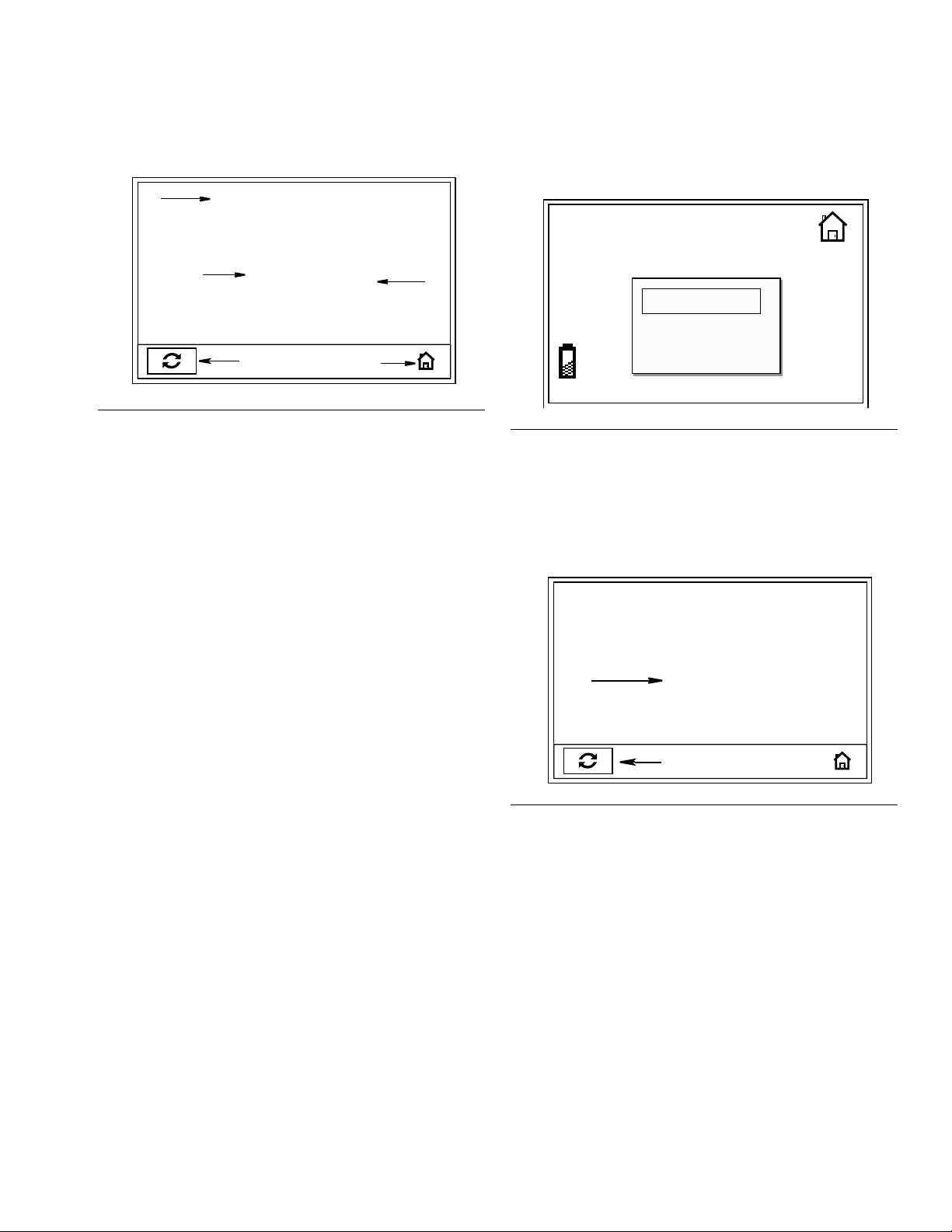
Totals Screen (FIG. 26)
All Meters
M
3485
N
F
IG. 26
See F
IG. 26 for terms F, G, M - P
F. Hom e Ico n: Returns user to Home Screen.
G. Reset: Resets counter (M) to zero.
M. Resettable Total: Shows cumulative amount that
has been dispensed in all modes. Can be reset to zero
at any time with Reset button (G).
N. Total: Shows cumulative amount that has been
dispensed in all modes for the life of the unit. Cannot
be reset.
14953
QTS
GAL
FG
ti12190a
To display Totals Screen:
If the display was asleep, press any button to wake up
the display.
MOBIL
5W-20
1
MANUAL
PRESET
TOTALS
ti12243a
FIG. 27
1. From HOME screen, use the UP or DOWN
ARROWS to select TOTALS (F
2. Press center, ENTER button to confirm selection.The Totals screen (F
3. To reset Resettable Total field (M) to zero, use LEFT
or RIGHT ARROW to move curser over RESET button (G).
4. Press center ENTER button to reset the displayed
amount in field M to zero.
IG. 27).
IG. 26) appears.
When the Total (N) reaches 999,999 the count resets
automatically to 000.
312865G 23
Page 24

Troubleshooting
Troubleshooting
• Relieve pressure, page 7, before you check or repair the meter. Be sure all other valves, controls and pump are
operating properly.
• When calling for Technical Assistance you may be asked to provide the Software Version that is being used by
your meter. Refer to F
meter.
Problem Cause Solution
Battery icon is blinking. Batteries are low. Replace batteries, page 27.
Display does not activate.
Cannot read display Contrast is set too high or too low to
IG. 10, page 11, item #1 for help determining where this information is shown on your
Batteries are defective. Replace batteries, page 27.
Electronic control is malfunctioning. Replace the electronic bezel assem-
bly. (See Manual Meters Parts page
34 or Preset Meters Parts page 36 to
identify which kit is required for your
meter).
Adjust contrast. See Adjusting
be viewed in work area
Screen Contrast Using LEFT or
RIGHT ARROWS, page 10.
1. Relieve pressure, page 7.
2. Clean or replace filter. Order Fil-
Filter is clogged.
Pump pressure is low. Increase pump pressure.
Twist lock nozzle not fully open. Aim nozzle into bucket or rag. Fully
Slow or no fluid flow.
Shut-off valve is not fully open. Fully open shut-off valve.
Foreign material is jammed in the
meter housing.
Displayed dispensed amount is not
accurate.
Meter leaks from cover/control. Poor seal at metering cover chamber. Contact your Graco distributor for
Unit needs to be calibrated for the
fluid that is being dispensed.
ter Kit 255885.
3. If the problem remains, contact
your Graco distributor for repair
or replacement.
open nozzle.
Do not trigger meter when nozzle
is closed! If you do accidentally trig-
ger the meter with the nozzle closed,
point nozzle into a waste bucket and
open the nozzle to relieve pressure
and expel built up fluid.
Contact your Graco distributor for
repair or replacement.
Calibrate the meter for the fluid that is
being dispensed. See Calibrate
Screen, page 14.
repair or replacement.
24 312865G
Page 25

Problem Cause Solution
Preset Models only - Trigger does not
reset sufficiently to dispense fluid.
Meter leaks from twist lock nozzle.
• It is important to distinguish
between the two causes of this
problem. A new nozzle will NOT
correct a fluid leak caused by a
faulty valve.
Meter leaks from swivel.
Unit does not stop dispensing when
assumed preset amount is dispensed.
Troubleshooting
Excessive dirt buildup is causing trip
rod to stick.
Twist lock nozzle has a damaged
seal.
Valve has damaged or obstructed
seals.
Clean trip rod or replace (page 28).
Order Kit 255889.
Replace nozzle. See Step 1 in Installation Procedure, page 9.
Clean valve stem and o-rings or
replace. Order Kit 255888.
Poor swivel/hose connection. Apply PTFE tape (leave a minimum 2
engaged threads uncovered for electrical continuity) or sealant to threads
of hose and tighten the connection.
See Step 3 in Installation Procedure,
page 8.
Poor swivel/meter housing connec-
Torque the fitting to 20-25 ft.-lbs.
tion.
Swivel seals have deteriorated and
Replace swivel.
leak.
Valve is dirty. Clean valve.
Low battery. Replace batteries, page 27.
Solenoid not functioning (Preset
Replace solenoid.
only).
312865G 25
Page 26

Troubleshooting
Error Codes
Error codes are listed below. Even in an error condition the unit keeps track of the amount dispensed. With any error
code displayed you can:
• Select Manual option on Home Screen.
Error code is cleared. Unit switches to Manual mode and dispensed amount is displayed.
• Select reset option.
Error code is cleared, Unit switches to Auto mode and the present amount is displayed.
Error Code Cause Solution
Err 1 Battery voltage is low Change battery, page 27.
Ensure that your flow rate is not
higher than 14 gpm (37.8 lpm). For
further assistance, contact your
Graco distributor.
Select Reset, item G, page 19.
Check for low battery symbol and
replace batteries if indicated, page
27. For further assistance, contact
your Graco distributor.
Navigate to Home screen. Then
re-enter Dispense Screen.
Select Reset, item G, page 19 and
dispense again.To change the
shut-off default amount, see
Units/Limits Screen, page 13.
Enter an amount that is not zero. See
Preset Dispense Screen, page 20.
Change battery, page 27.
Err 2
Err 4
Err 5
Err 6
Switch Error: Error occurred with
pick-up in internal gear.
or
Unit was dropped or unit encountered
excessive vibration during shipping.
Flow has continued after it should
have shut off.
or
Flow has occurred in lockout condition.
In Manual Mode only.
The unit has dispensed the shut-off
default amount and has stopped fluid
flow.
A present dispense amount of zero
was entered for the dispense or is
stored as the default and a Preset
dispense was attempted.
Battery voltage is too low.
or
Err7
26 312865G
CAP ERROR: Error has occurred in
control.
Replace the electronic bezel assembly. (See Manual Meters Parts page
34 or Preset Meters Parts page 36 to
identify which kit is required for your
meter).
Page 27

Service
See Parts List, page 41, for reference numbers included in the following Service instructions.
Replacing the Battery
• Only use the size and type of batteries specified in
this manual.
Batteries required to meet life expectancy:
• Energizer E91
• Be sure to follow the correct polarity when
installing batteries in the battery compartment
(F
IG. 28). Reversed batteries may damage this
meter.
Service
47
• Do not mix different types of batteries together or
old batteries with fresh ones. Always replace all 4
batteries with 4, fresh, new batteries.
The low battery and dead battery displays are explained
in the Troubleshooting Table, page 24.
To change the battery:
1. Press firmly on battery compartment cover. Using a
flat screwdriver turn latch screw counter-clockwise
1/2 turn.
2. Remove the battery compartment cover and batteries.
3. Install new batteries. See F
IG. 28 for battery orienta-
tion.
ti10984a
FIG. 28
4. Replace cover. The cover is designed to only fit on
battery compartment one way. The notch (a) on
cover fits into slot (b) on compartment. (F
.
IG. 29).
(b)
(a)
F
IG. 29
5. Press down firmly on cover. Using a flat screwdriver
turn latch screw clockwise 1/2 turn.
312865G 27
Page 28

Service
Trip Rod Repair
(SDP5 & SDP15 Meters Only)
Disassembly
1. Relieve Pressure, page 7.
2. Use a Torx (T20) wrench to remove 4 corner screws
(A) located on the bottom of the meter (F
Keep these screws for reassembly.
A
IG. 30).
A
4. With your finger, carefully
lift up clip (D) to discon-
nect battery lead (B) from battery module.
B
D
ti11938a
F
IG. 32
NOTICE
Do not use a screw driver or any other tool to lift up
clip (D) when disconnecting battery lead (B) from battery module. If the clip is damaged or broken it cannot
be repaired; you will have to replace the battery module. Order Part No. 255197.
ti11936a
FIG. 30
3. Turn meter over and tilt cover back (F
IG. 31).
You will not be able to completely remove the cover
until you disconnect the leads to the battery, solenoid and remove the reed switch PCB.
C
B
D
5. Unsnap solenoid lead (C) (F
C
F
IG. 33
IG. 33).
ti11939a
ti11937a
F
IG. 31
28 312865G
Page 29

Service
6. Remove two screws (D) holding reed switch board
to the cover plate (F
IG. 34). Keep these screws for
reassembly. Remove cover assembly.
D
ti11940a
F
IG. 34
7. Remove and discard o-ring (5) (F
IG. 35).
8. Remove guard (9) by inserting your thumb or finger
behind the cover and pry it loose. Then slide guard
down and out of groove on housing (F
9
IG. 36).
ti12009a
FIG. 36
9. Unscrew solenoid (12) and remove from meter
housing (F
IG. 37). If necessary, a pliers can be used
to loosen solenoid.
F
IG. 35
12
5
ti11941a
ti12238a
IG. 37
F
312865G 29
Page 30

Service
10. Place meter in a vise as shown in FIG. 38. Use new
trip rod from your kit (2) or a non-metal rod or dowel
to push trip rod through meter housing (F
F
IG. 39) far enough to access pin (19) holding
IG. 38 and
together trip rod and trigger.
19
ti12011a
F
IG. 38
11. Use a pick to push pin (19) out (F
IG. 39).
13. Remove trip rod assembly from meter housing.
Be careful when you remove the trip rod assembly.
Cover the balls with your fingers or a rag to prevent
them from falling out.
6
ti12013a
F
IG. 41
Cleaning Trip Rod
a. If the trigger does not reset sufficiently to dis-
pense fluid, clean trip rod and spring with a soft
brush and cleaning fluid such as mineral spirits.
19
ti12012a
IG. 39
F
12. Remove trigger assembly (6) from meter housing.
6
ti12016a
F
IG. 40
b. Inspect trip rod and spring. If damaged, replace
using Trip Rod Replacement Kit 255889.
30 312865G
Page 31

Service
Reassembly
Use all the new parts provided in the kit. Do not reuse
the old parts.
1. Insert balls (3) in trip rod (2) (F
2. Slide spring (1) over trip rod (2) (F
IG. 42).
IG. 42).
3
2
1
ti12014a
5. Install trigger assembly (8) (F
IG. 44). Push pin (19)
through holes in trigger and trip rod assembly.
8
19
FIG. 44
6. Install solenoid (12). Finger tighten securely.
12
2
ti12015a
F
IG. 42
3. Insert trip rod assembly in opening in meter housing
(F
IG. 43).
IG. 43
F
4. Turn meter over and place in vise. Align holes in trigger assembly with holes in trip rod (2). Use the old
trip rod or a non-metal rod or dowel to push trip rod
up and out of the meter housing (F
IG. 44) far enough
to see hole for pin (19) to slide into, however, do not
install pin in this step.
ti12238a
IG. 45
F
7. Install o-ring (5).
5
IG. 46
F
ti11941a
312865G 31
Page 32

Service
8. Reinstall reed switch board in meter housing. Use 2
screws (D) to secure reed switch PCB to cover
plate. Tighten screws until they bottom out.
NOTICE
Do not use a screw driver or any other tool to lift up
clip (D) when reconnecting battery lead (B). If the clip
is damaged or broken it cannot be repaired; you will
have to replace the battery module. Order Part No.
255197.
D
ti11940a
F
IG. 47
9. Reconnect lead (B) to battery by carefully sliding
connector over battery terminals (E) until it snaps
securely into place under clip (D) (F
IG. 48).
ED
ti11938ab
D
10. Reconnect solenoid lead (C) (F
IG. 49).
C
F
IG. 49
11. Position cover over meter housing.
ti11939a
NOTICE
When replacing cover, be careful not to pinch wires.
IG. 48
F
32 312865G
Page 33

12. Replace 4 screws (A). Torque each to 24-35 inch
pounds.
A
A
ti11936a
F
IG. 50
13. Install guard (9).
Service
IG. 51
F
9
ti12009a
312865G 33
Page 34

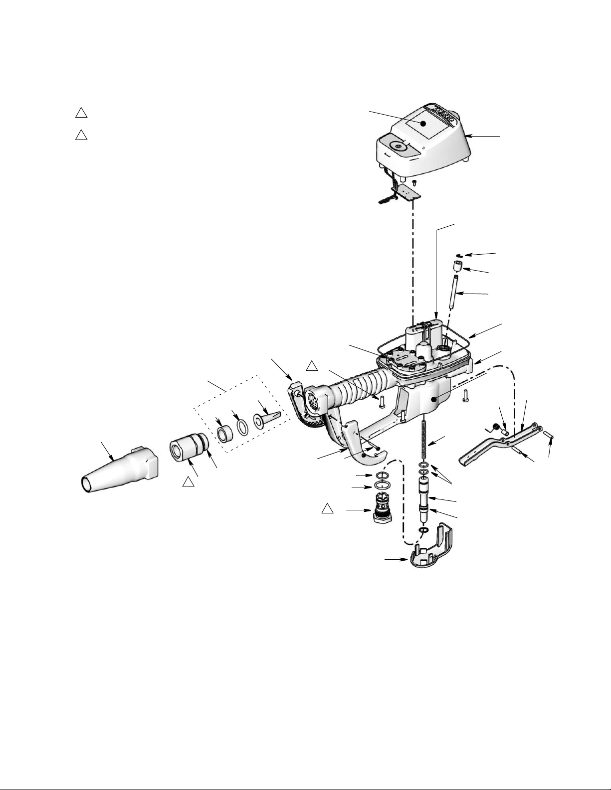
SDM5 & SDM15 Manual Meters Parts
SDM5 & SDM15 Manual Meters Parts
(
Ref Part Description Qty
2 115477 SCREW, mach, torx pan hd 6
5 120812 O-RING, seal 1
6 15K418 TRIGGER, meter 1
9 15K464 GUARD, bumper 1
11 HOUSING, meter 1
13 15K600 CARTRIDGE, valve 1
14 15W020 STEM, valve 1
17 255197 MODULE, battery 1
18 256493 KIT, repair, electronic bezel,
includes 18a and instruction man-
ual 312942
18a LABEL, control, overlay 1
19 120850 PIN, dowel M4 2
24 255888 KIT, repair, valve and seal
includes 24a-24e and instruction
manual 312939
24a PACKING, o-ring 1
24b PACKING, o-ring 1
24c PACKING, o-ring 1
24d O-RING, 2
24e SPRING, compression 6.1 x 76mm 1
28 120853 PIN, dowel 1
31 247344 SWIVEL, straight, 1/2-14 NPT,
includes 31a (used with 255348,
255349, 255350, 255802, 255803,
255804, 256836, 256837)
247345 SWIVEL, straight, 3/4-14 NPT
includes 31a (used with 255800,
255801)
31a 105765 O-RING 1
32 15T366 BOOT, swivel, 3/4” hose, black
(standard with meter)
15T367 BOOT, swivel, 3/4” hose, red 1
15T368 BOOT, swivel, 3/4” hose, blue 1
15T369 BOOT, swivel, 3/4” hose, green 1
15T370 BOOT, swivel, 3/4” hose, yellow 1
34 255885 KIT, filter, includes 34a-34c
34a FILTER, wire, 40 mesh 10
34b PACKING, o-ring 10
34c SPACER, strainer 10
39 15R057 BUSHING, stationary, rod 1
40 15R056 ROD, stationary 1
41 115999 RING, retaining 1
47 121413 BATTERY, pkg, 4 count, alkaline,
AA (page 27)
49▲ 15T259 LABEL, CE 1
50 15T492 SPACER, 1/4 OD x 0.9 th 4
51 15T603 GUARD, right 1
52 15T604 GUARD, left 1
53 117436 SCREW, thd forming 2
1
1
1
1
▲ Replacement Danger and Warning labels, tags and
cards are available at no cost.
34 312865G
Page 35
SDM5 & SDM15 Manual Meters Parts
3
Torque to 25-35 IN. LBS
5
Torque to 20-30 FT. LBS
34
34c
34b
34a
52
18a
18
17 / 47
41
39
40
5
28
3
2
49
50
11
6
32
24e
51
53
31a
31
5
24b
24c
13
5
24d
14
19
24a
9
ti11916b
312865G 35
Page 36

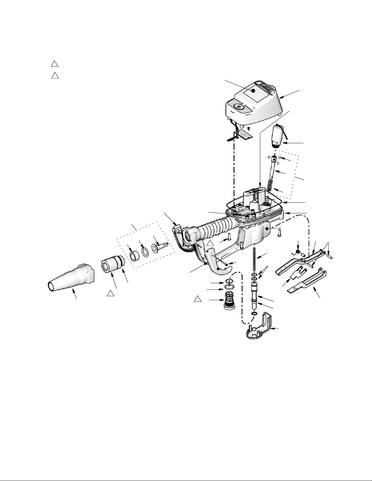
SDP5 & SDP 15 Preset Meters Parts
SDP5 & SDP 15 Preset Meters Parts
(
Ref Part Description Qty
2 115477 SCREW, mach, torx pan hd 6
3 255889 KIt, repair, trip rod, includes 3a-3c
and instruction manual 312944
3a BALL,5 MM, carbide 3
3b ROD 1
3c SPRING, compression 10.67 mm 1
5 120812 O-RING, seal 1
6 15K418 TRIGGER, meter 1
7 15K443 ARM, trip 1
8 15K446 PLATE, ratchet 1
9 15K464 GUARD, bumper 1
11 HOUSING, meter 1
12 15W093 SOLENOID 1
13 15K600 CARTRIDGE, valve 1
14 15W020 STEM, valve 1
15 15K602 SPRING, torsion 1
17 255197 MODULE, battery 1
18 256494 KIT, repair, electronic bezel,
includes 18a and instruction man-
ual 312942
18a LABEL, control, overlay 1
19 120850 PIN, dowel M4 2
24 255888 KIT, repair, valve and seal,
includes 24a-24e and instruction
manual 312939
24a PACKING, o-ring 1
24b PACKING, o-ring 1
24c PACKING, o-ring 1
24d O-RING, 2
24e SPRING, compression 6.1 x 76mm 1
28 120853 PIN, dowel 1
31 247344 SWIVEL, straight, 1/2-14 NPT,
includes 31a (used with 255200,
255351, 255352, 255355, 255356,
256838, 256839)
247345 SWIVEL, straight, 3/4-14 NPT
includes 31a (used with 255353,
255354)
31a 105765 O-RING 1
32 15T366 BOOT, swivel, 3/4” hose, black
(standard with meter)
15T367 BOOT, swivel, 3/4” hose, red 1
15T368 BOOT, swivel, 3/4” hose, blue 1
15T369 BOOT, swivel, 3/4” hose, green 1
15T370 BOOT, swivel, 3/4” hose, yellow 1
34 255885 KIT, filter, includes 34a-34c 1
34a KIT, filter, wire, 40 mesh 10
34b PACKING, o-ring 10
34c SPACER, strainer 10
Ref Part Description Qty
47 121413 BATTERY, pkg, 4 count, alkaline,
1
49▲ 15T259 LABEL, CE 1
51 15T603 GUARD, right 1
52 15T604 GUARD, left 1
53 117436 SCREW, thd forming 2
▲ Replacement Danger and Warning labels, tags and
cards are available at no cost.
1
1
1
1
AA (page 27)
1
36 312865G
Page 37
3
Torque to 25-35 IN. LBS
5
Torque to 20-30 FT. LBS
SDP5 & SDP 15 Preset Meters Parts
18a
18
17 / 47
12
3a
32
3b
3
3c
5
52
28
11
34
49
15
6
19
34c
34b
34a
2
3
24e
53
24d
51
31a
31
5
24c
5
24b
13
14
7
8
24a
ti10617a
9
312865G 37
Page 38

Nozzle (33) and Extension (20) Kits
Nozzle (33) and Extension (20) Kits
Part No. Description Fluid Type
255852*
255853*
255854
Automatic, non-drip quick close nozzle with
rigid extension.
Automatic, non-drip quick close nozzle with
flexible extension
Non-drip, quick close nozzle with rigid
extension
Oil
Oil
Gear Lube
ti11827
ti11826
ti11827
ti11825
ti11830
ti11831
255855*
255856*
Non-drip, quick close nozzle with rigid extension
Non-drip, quick close nozzle with flexible
extension
*Used for dispensing 5gpm (22.7 lpm) or less.
Anti-freeze
Anti-freeze
ti11828
ti11826
ti11828
ti11825
continued on page 32
38 312865G
Page 39

Part No. Description Fluid Type
Nozzle (33) and Extension (20) Kits
255857
255858
Non-drip, quick close, high-flow nozzle with
rigid extension
Non-drip, quick close, high flow nozzle with
flexible extension
Oil and
Anti-freeze
Oil and
Anti-freeze
ti11826
ti11829
ti11829
ti11825
312865G 39
Page 40

Nozzle (33) and Extension (20) Kits
Nozzle (33) Kits
255459* Automatic, non-drip, quick-close nozzle Qty Oil
• BODY, nozzle 1
• O-RING, packing 1
• SPRING, compression 1
• O-RING, packing 1
• STEM, nozzle, valve 1
• SEAT, valve 1
255460* Automatic, non-drip, quick-close nozzle Anti-freeze
• BODY, nozzle 1
• SPRING, compression 1
• O-RING, packing 1
• STEM, nozzle, valve 1
• O-RING, packing 1
• SEAT, valve 1
255461 Automatic, non-drip, high-flow nozzle Oil and Antifreeze
• STEM, nozzle 1
• BODY, nozzle 1
• O-RING, packing 1
• O-RING, packing 1
• O-RING, packing 1
255470 Non-drip, quick-close nozzle Gear Lube
• Housing 1
• Body, nozzle 1
• O-RING, packing 1
• O-RING, packing 1
• Plug, Hollow, hex 1
*Used for dispensing 5gpm (22.7 lpm) or less.
Thermal Relief Kits (page 6)
Part No. Description PSI (bar) Rating
112353 Diaphragm pump for fuel dispense, valve only 50 psi (.34 MPa, 3.4 bar)
235998
237601 Fire-Ball 425, 3:1 600 psi (4.1 MPa, 41 bar)
237893 Fire-Ball 300, 5:1 900 psi (6.2 MPa, 62 bar)
248296 Fire-Ball 300, 5:1 (same as 237893 without bung
238899 Diaphragm pump 150 psi (1 MPa, 10.4 bar)
240429 Fire-Ball 425, 6:1 and 10:1 1600 psi (11 MPa, 110 bar)
248324 Fire-Ball 425, 6:1 and 10:1 (same as 240429
40 312865G
Mini Fire-Ball
adapter and swivel. Includes 6-foot hose)
minus bung adapter and swivel. Includes 6-foot
hose)
™
225, 3:1
600 psi (4.1 MPa, 41 bar)
900 psi (6.2 MPa, 62 bar)
1600 psi (11 MPa, 110 bar)
Page 41

Technical Data
Technical Data
Flow range* 0.26 to 14 gpm (1 to 53 lpm)
Maximum Working Pressure 1500 psi (10 MPa, 103.4 bar)
Maximum Working Pressure
(50:50 antifreeze/water mix) 900 psi (6.2 MPa, 62 bar)
Units of Measure pints, quarts, gallons, liters (factory set to quarts)
Weight 5 pounds (2.26 kg)
Dimensions (without extension)
Length 13 inches (33 cm)
Width 3.75 inches (9.5 cm)
Height 5.75 inches (14.6 cm)
Units of measure factory set in quarts
maximum totalizer amount = 999,999 gallons or liters
maximum recorded dispensed volume = 999.99 units
maximum preset volume (Preset only) = 999.9 units
Inlet 1/2-14 npt or 3/4-14 npt
Outlet 3/4-16 straight thread o-ring boss
Operating temperature range 4 °F to 158°F (-4°C to 70°C)
Storage temperature range -40°F to 150°F (-40°C to 70°C)
Battery** 4AA alkaline or lithium batteries
Expected battery life in typical shop
environment
Wetted parts aluminum, stainless steel, PBT/PC, zinc,
nitrile rubber, CS
Fluid compatibility antifreeze, gear oil, crankcase oil, ATF
Meter pressure loss 80 psi @ 10 gpm
Accuracy† +/- 0.5 percent
1 year
*Tested in 10W motor oil. Flow rates vary with fluid pressure, temperature and viscosity.
®
**Battery required to meet life expectancy: Energizer
† At 2.5 gpm (9.5 lpm), at 70°F (21°C), with 10-weight oil and 1 gallon dispensed. May require calibration; out-of-box
accuracy is +/- 1.25 percent.
312865G 41
Alkaline E91.
Page 42

Graco Extended Metered Dispense Valve Warranty
Graco warrants all equipment referenced in this document which is manufactured by Graco and bearing its name to be free from defects in
material and workmanship on the date of sale to the original purchaser for use. Graco will, for a period of five (5) years from the date of sale, repair
or replace any non-electronic part of the equipment determined by Graco to be defective. Graco will also for a period of three (3) years from the
date of sale, repair, or replace any meter electronic components determined by Graco to be defective. This warranty applies only when the
equipment is installed, operated and maintained in accordance with Graco’s written recommendations.
This warranty does not cover, and Graco shall not be liable for general wear and tear, or any malfunction, damage or wear caused by faulty
installation, misapplication, abrasion, corrosion, inadequate or improper maintenance, negligence, accident, tampering, or substitution of
non-Graco component parts. Nor shall Graco be liable for malfunction, damage or wear caused by the incompatibility of Graco equipment with
structures, accessories, equipment or materials not supplied by Graco, or the improper design, manufacture, installation, operation or
maintenance of structures, accessories, equipment or materials not supplied by Graco.
This warranty is conditioned upon the prepaid return of the equipment claimed to be defective to an authorized Graco distributor for verification of
the claimed defect. If the claimed defect is verified, Graco will repair or replace free of charge any defective parts. The equipment will be returned
to the original purchaser transportation prepaid. If inspection of the equipment does not disclose any defect in material or workmanship, repairs will
be made at a reasonable charge, which charges may include the costs of parts, labor, and transportation.
THIS WARRANTY IS EXCLUSIVE, AND IS IN LIEU OF ANY OTHER WARRANTIES, EXPRESS OR IMPLIED, INCLUDING BUT NOT LIMITED
TO WARRANTY OF MERCHANTABILITY OR WARRANTY OF FITNESS FOR A PARTICULAR PURPOSE.
Graco’s sole obligation and buyer’s sole remedy for any breach of warranty shall be as set forth above. The buyer agrees that no other remedy
(including, but not limited to, incidental or consequential damages for lost profits, lost sales, injury to person or property, or any other incidental or
consequential loss) shall be available. Any action for breach of warranty must be brought within two (2) years of the date of sale.
GRACO MAKES NO WARRANTY, AND DISCLAIMS ALL IMPLIED WARRANTIES OF MERCHANTABILITY AND FITNESS FOR A
PARTICULAR PURPOSE, IN CONNECTION WITH ACCESSORIES, EQUIPMENT, MATERIALS OR COMPONENTS SOLD BUT NOT
MANUFACTURED BY GRACO. These items sold, but not manufactured by Graco (such as electric motors, switches, hose, etc.), are subject to
the warranty, if any, of their manufacturer. Graco will provide purchaser with reasonable assistance in making any claim for breach of these
warranties.
In no event will Graco be liable for indirect, incidental, special or consequential damages resulting from Graco supplying equipment hereunder, or
the furnishing, performance, or use of any products or other goods sold hereto, whether due to a breach of contract, breach of warranty, the
negligence of Graco, or otherwise.
FOR GRACO CANADA CUSTOMERS
The Parties acknowledge that they have required that the present document, as well as all documents, notices and legal proceedings entered into,
given or instituted pursuant hereto or relating directly or indirectly hereto, be drawn up in English. Les parties reconnaissent avoir convenu que la
rédaction du présente document sera en Anglais, ainsi que tous documents, avis et procédures judiciaires exécutés, donnés ou intentés, à la suite
de ou en rapport, directement ou indirectement, avec les procédures concernées.
Graco Information
For the latest information about Graco products, visit www.graco.com.
TO PLACE AN ORDER, contact your Graco distributor or call to identify the nearest distributor.
Phone: 612-623-6928 or Toll Free: 1-800-533-9655, Fax: 612-378-3590
All written and visual data contained in this document reflects the latest product information available at the time of publication.
Graco reserves the right to make changes at any time without notice.
Original instructions. This manual contains English. MM 312865
Graco Headquarters: Minneapolis
International Offices: Belgium, China, Japan, Korea
GRACO INC. P.O. BOX 1441 MINNEAPOLIS, MN 55440-1441
Copyright 2008, Graco Inc. is registered to ISO 9001
www.graco.com
Revised 04/2010
 Loading...