

Page 1
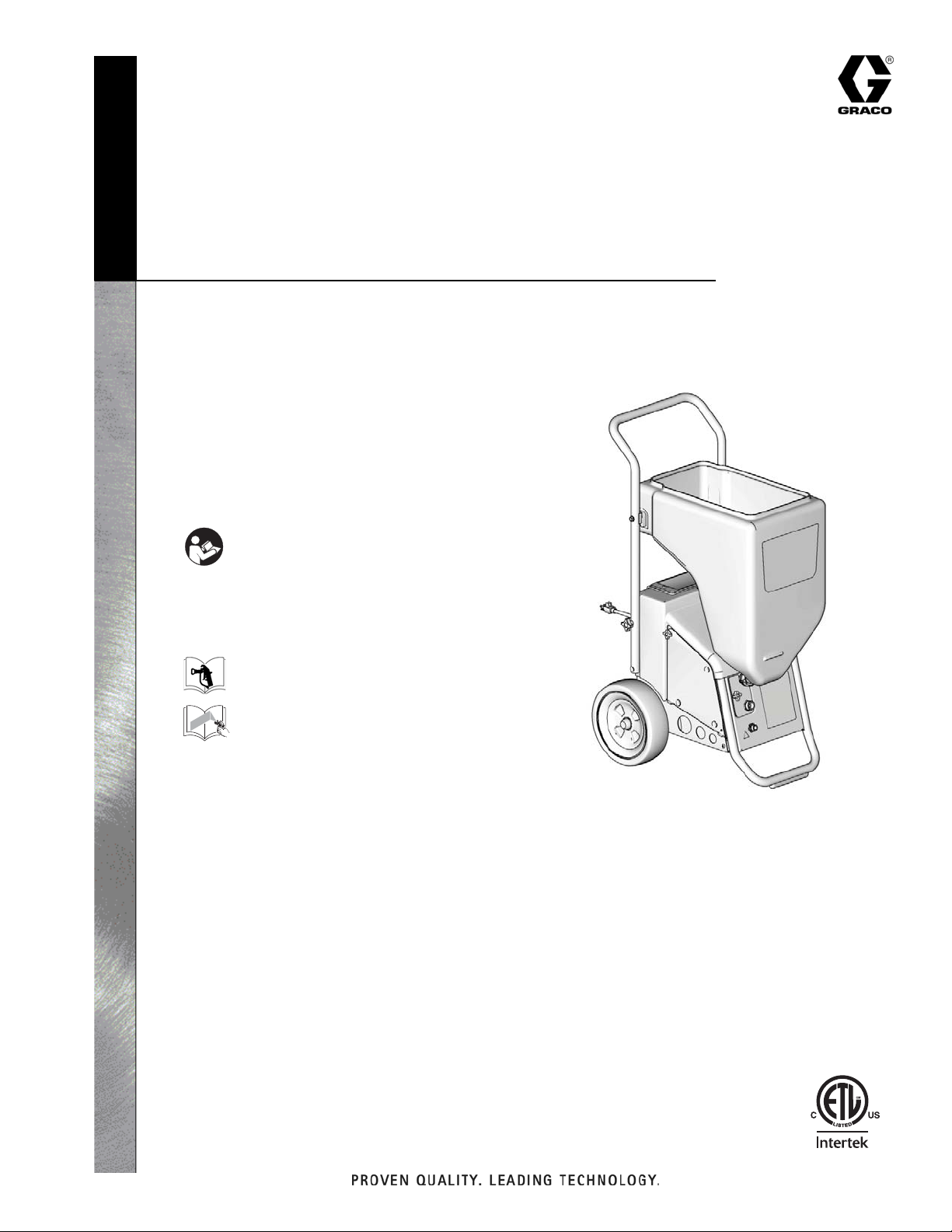
Model 254975 Shown
ti8867a
Repair
Interior Texture Sprayers
RTX 900 & RTX 1250
-For Water-Based Materials Only-
Models: 254974 and 254975
70 psi (0.49 MPa, 4.9 bar)
Maximum Fluid Working Pressure
311772P
EN
Important Safety Instructions
Read all warnings and instructions in this manual.
Save these instructions.
Related Manuals
311777
311768
Page 2
Warnings
Warnings
The following are general warnings related to the setup, use, grounding, maintenance and repair of this equipment.
Additional, more specific warnings may be found throughout the body of this manual where applicable. Symbols
appearing in the body of the manual refer to these general warnings. When these symbols appear through the
manual, refer back to these pages for a description of the specific hazard.
WARNINGS
Fire and Explosion Hazard
Improper grounding, poor ventilation, open flames or sparks can cause a hazardous condition and result
in fire or explosion and serious injury.
• The system is for use with water-based materials only. Only use fluids compatible with the
equipment. Refer to Technical Data of all equipment manuals. Read fluid and solvent manufacturers
warnings.
• Ground all equipment in the work area. See Grounding and Electrical Requirements, page 6.
• If there is any static sparking or you feel an electric shock while using this equipment, stop spraying
immediately. Do not use the equipment until you identify and correct the problem.
• Keep work area free of debris, including solvent, rags and gasoline.
• Comply with all applicable state and national fire, electrical and safety regulations.
• Keep a fire extinguisher in the work area.
Equipment Misuse Hazard
Equipment misuse can cause equipment to rupture, malfunction, or start unexpectedly and cause serious
injury.
• Before operating this equipment, read all manuals, tags, and labels, including material labels and
instructions.
• Do not expose system to rain. Always store system indoors.
• Do not alter or modify equipment.
• Do not spray cementitious materials.
• Do not exceed maximum working pressure of lowest rated component in your system.
• Check equipment daily. Repair or replace worn or damaged parts immediately.
• To reduce risk of serious injury, including electric shock and splashing fluid in eyes, follow Pressure
Relief Procedure on page 6 before servicing the unit.
• Do not kink or over bend hoses or use hoses to pull equipment.
• Route hoses away from traffic areas, sharp edges, moving parts and hot surfaces. Do not expose
Graco hoses to temperatures above 130° F (55° C) or below -35° F (-37° C).
• Air hoses at the compressor end, can get very hot! Allow sprayer to cool down 15 minutes before
removing air hose.
• Store hazardous fluid in an approved container. Dispose of hazardous fluid according to all local,
state and national guidelines.
• Never directly inhale compressed air. Compressed air may contain toxic vapors.
2 311772M
Page 3
Warnings
WARNINGS
Electric Shock Hazard
To reduce the risk of electric shock:
• Be sure sprayer is adequately grounded through electrical outlet, page 6.
• Use only 3-wire, extension cords.
• Make sure ground prongs are intact on sprayer and extension cords.
• Do not operate with cover removed.
• Turn off sprayer. Follow Pressure Relief Procedure, page 6, and unplug unit, before removing any
parts.
Pressurized Equipment Hazard
Fluid from gun, leaks or ruptured components can splash in the eyes or on skin and cause serious injury.
• Follow Pressure Relief Procedure, page 6 when you stop spraying and before cleaning, checking
or servicing.
• Do not point spray gun at anyone; put hand, fingers or rag over nozzle, or stop or deflect leaks with
your hand, body, glove, or rag.
• Wear protective clothing, gloves, and eyewear.
Cleaning Solvent Hazard with Plastic Parts
Use only compatible water-based solvents to clean plastic structural or pressure-containing parts. Many
solvents can degrade plastic parts to the point where they could fail. Such failure could cause serious
injury or property damage. See Technical Data on page 33 of this instruction manual and in all other
equipment manuals. Read fluid and solvent manufacturer’s warnings.
Burn Hazard
Equipment surfaces and fluid that’s heated can become very hot during operation. To avoid severe burns,
do not touch hot fluid or equipment. Wait until equipment/fluid has cooled completely.
Personal Protective Equipment
You must wear appropriate protective equipment when operating, servicing, or when in the operating
area of the equipment to help protect you from serious injury, including eye injury, inhalation of toxic
fumes, burns, and hearing loss. This equipment includes but is not limited to:
• Protective eyewear
• Clothing and respirator as recommended by the fluid and solvent manufacturer
• Gloves
• Hearing Protection
CALIFORNIA PROPOSITION 65
This product contains a chemical known to the State of California to cause cancer, birth defects or other
reproductive harm. Wash hands after handling.
311772M 3
Page 4
Warnings
ti9016a
ti9010a
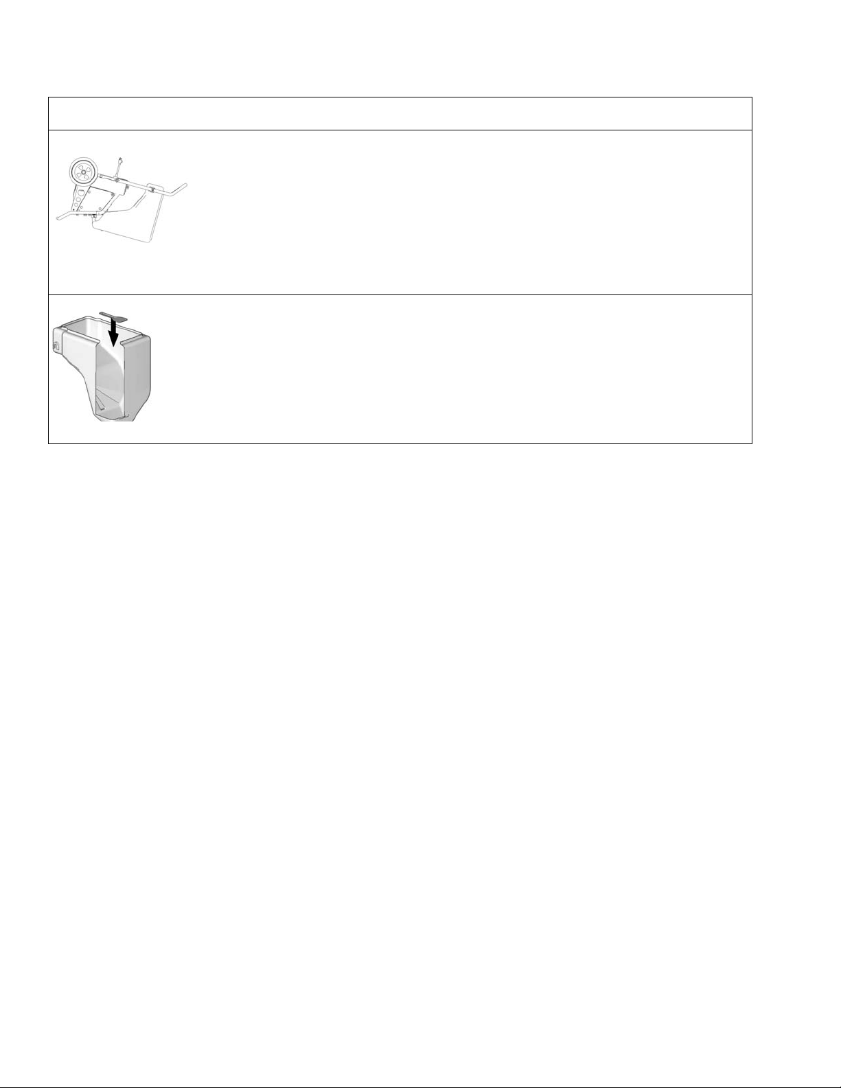
CAUTION
Water or material remaining in unit when temperatures are below freezing can damage
motor and/or delay pump startup.
To insure water and material are completely drained out of unit:
1. Remove material line from sprayer.
2. Tip sprayer up as shown.
Before adding material or starting unit in cold weather, run warm water through pump.
Before adding material to hopper, install burp guard. When only a small amount of material
remains in the hopper, the burp guard prevents material from shooting out when the unit is
turned off. This material could splash in the operator’s eyes or on skin, or into the air.
4 311772M
Page 5
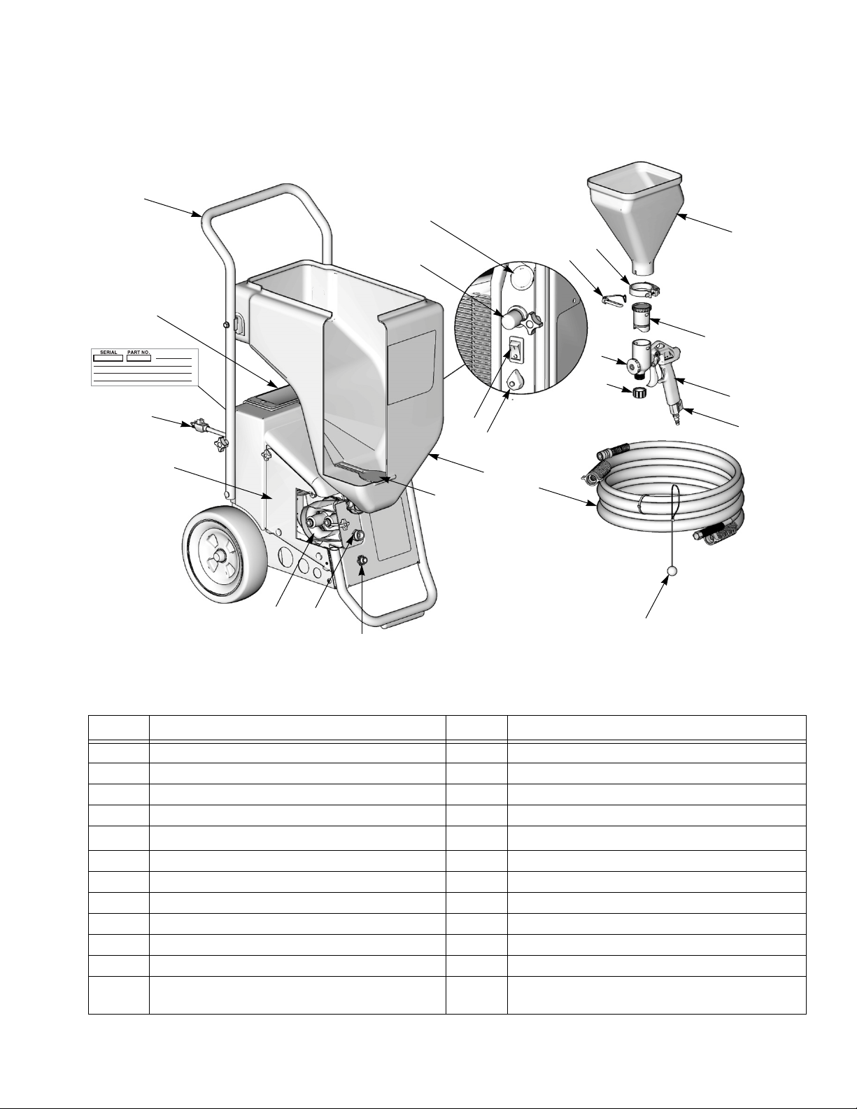
Component Identification
M
D
F
A
G
C
L
Model 254975 Shown
E
K
U
T
V
B
S
W
R
P
bb
N
H
J
ti8939a
cc
dd
Component Identification
Item Component Item Component
A Handle N Burp Guard
B Toolbox P Material/Air Hose
C Power Cord (120V, 25 ft) Q Accessories Bag
D Side Pump Access Panel (RTX 1250 Only) R Material Thickness Gauge
E
F Pump Hose Outlet T Hose Plug
G Air Hose Outlet U Touch-Up Hopper (3/4 gallon) (sold separately)
H Material Flow Gauge V Gun Plug
J Material Flow Control W Air Control
K ON/OFF Switch bb Hopper Clamp (sold separately)
L Selector Switch (Hopper Gun/Sprayer) cc Gun Plug Clip
M Material Hopper - 10 gallon, RTX 900
RotoFlex
Material Hopper - 12 gallon, RTX 1250
™
II Pump (inside)
SNozzle (4 Total)
dd Hopper Gun
311772M 5
Page 6
Component Identification
ti9221a
ti9084a
ti8528a
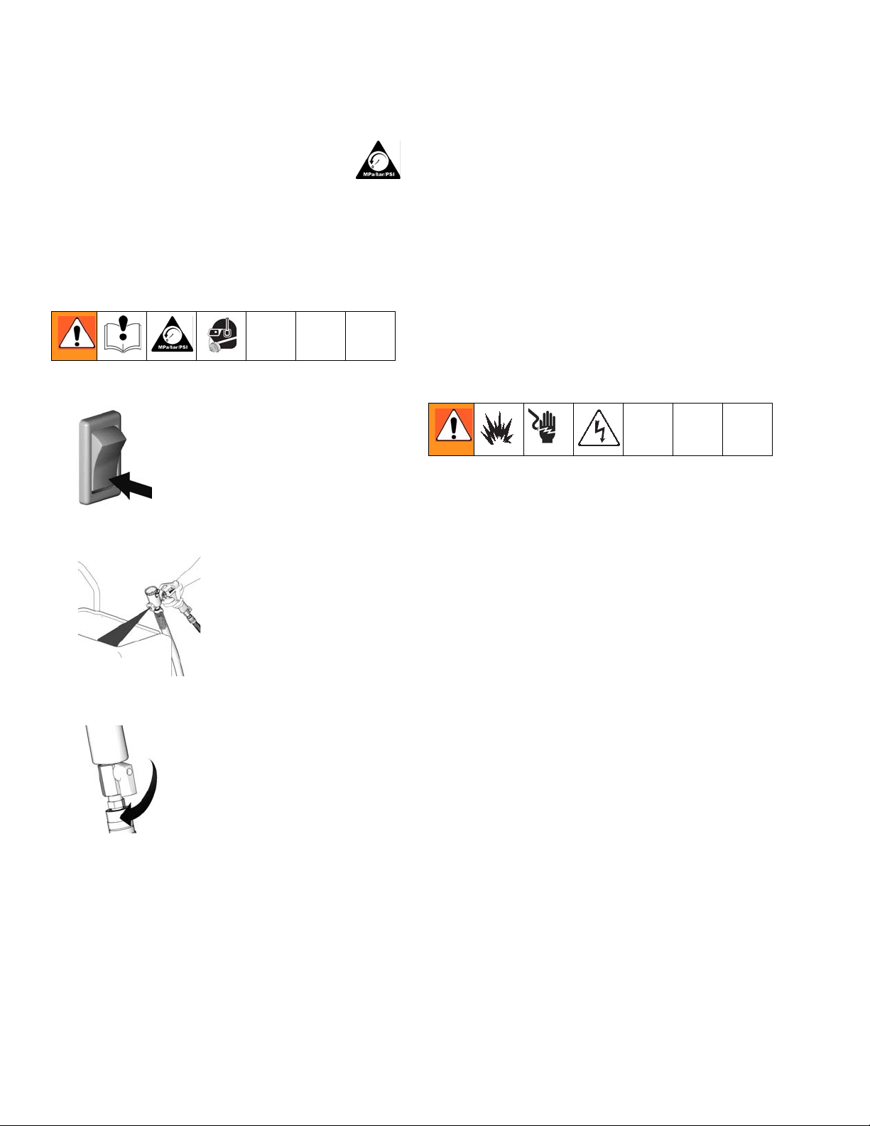
Pressure Relief Procedure
To reduce risk of injury, follow this procedure
whenever you see this symbol throughout this
manual, Also, perform this procedure
whenever you:
• Stop spraying
• Check or repair any part of this system
• Install or clean spray nozzle
1. Turn Power Switch OFF.
2. Trigger gun into material hopper.
Grounding and Electrical
Requirements
This sprayer must be grounded. Grounding reduces the
risk of electrical shock by providing an escape wire for
the electrical current. The sprayer cord includes a
grounding wire with an appropriate grounding plug. The
plug must be plugged into an outlet that is properly
installed and grounded in accordance with all local
codes and ordinances.
Check with a qualified electrician or if grounding
instructions are not completely understood, or if in doubt
as to whether the product is properly grounded. Do not
modify plug provided; if it will not fit the outlet, have
proper outlet installed by a qualified electrician.
120V AC Systems
• This equipment requires a 120V AC, 60 Hz, 15A
circuit with a grounding receptacle. Do not use an
adapter with this product.
3. Open gun air valve.
Extension Cords
• Use only an extension cord with an undamaged,
3-prong plug.
• For 25 to 50 ft (7.6 to 15.2 m) cords, use 3-wire, 14
AWG (1.5 mm
• For up to 100 ft. (30.48 m) cord, use 3-wire, 12
AWG (2.5 mm
2
) minimum.
2
) minimum.
Auxiliary Air Compressor
Do not use an auxiliary air compressor with this spray
system.
Generator Requirements
3500 W (3.5 KW) minimum.
Hose Size and Length
The system comes with a hose set consisting of a 3/4 in.
ID x 25 ft (25 mm x 7.6 m) material hose and a 3/8 in-ID
air hose. Do not use more than 25 ft (7.6m) of material
and air hose.
6 311772M
Page 7
Shroud Removal
ti2810b
ti8871a
ti8875a
14
12
ti8884a
31
2
30
ti8882a
31
70
ti8874a
ti8872a
42
ti9283a
30
ti8883a
5
7
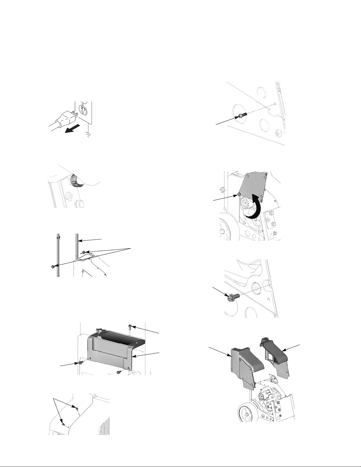
Shroud Removal
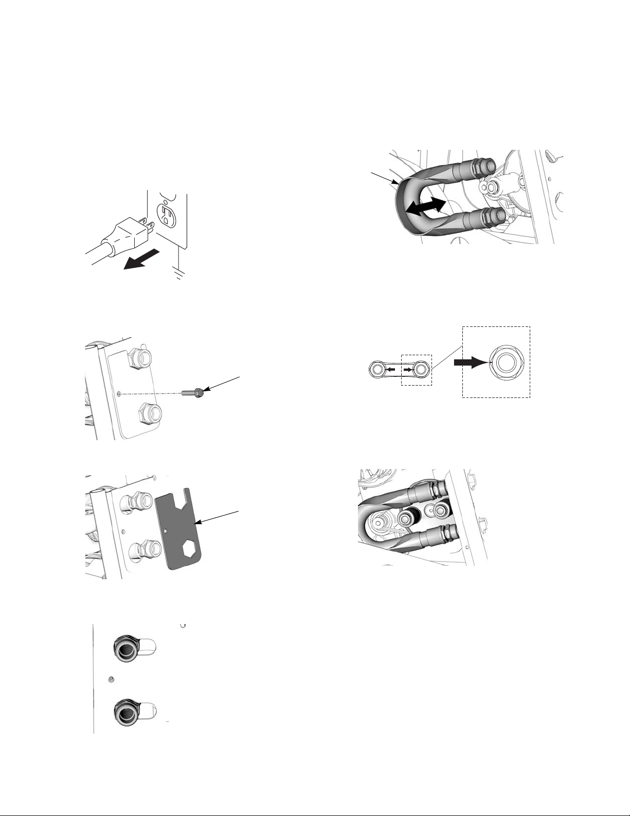
Disassembly
1. Relieve Pressure, page 6.
2. Unplug sprayer from outlet.
3. Loosen bottom hopper fitting by hand and pull
hopper up and off from handle.
4. Loosen and remove 2 knobs (14) on sprayer handle
(12).
8. Loosen and remove screw (70) from lower right corner of side access panel (RTX1250) only.
9. Loosen knob (42) on side access panel and swing
open door.
10. Use screwdriver to remove second screw (30).
5. Spread handle bars apart and pull up to remove
from sprayer.
6. Loosen screws (30) and screw (31) from toolbox
and remove toolbox (2) from sprayer.
11. Remove two shroud halves (5 and 7) from sprayer.
7. Loosen screws (31) on shroud.
311772M 7
Page 8
Shroud Removal
ti9015a
5
ti9283a
30
42
ti8938a
ti8874a
70
ti8884a
31
2
30
ti8882a
31
ti8875a
14
12
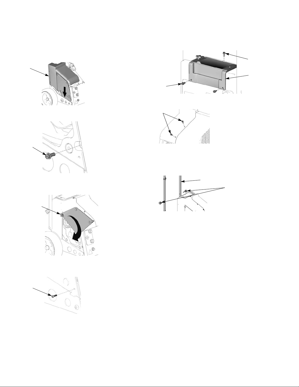
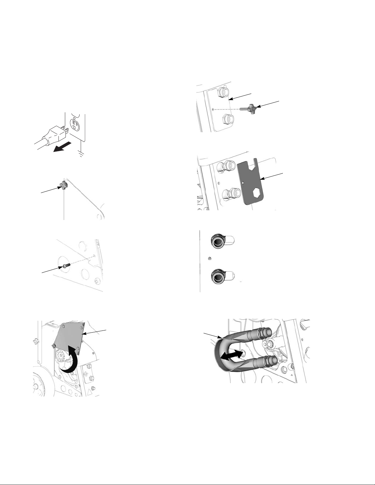
Reassembly
1. Angle left shroud half (5) into base and push down
into place. Then replace right shroud half (7).
2. Replace and tighten second screw (30).
5. Replace toolbox (2) and tighten screws (30) and
screw (31).
6. Tighten screws (31) on shroud.
7. Spread handle bars apart and slide handle down
into place.
8. Tighten 2 knobs (14) on sprayer handle (12).
3. Swing access door down (RTX 1250) and tighten
knob (42).
4. Tighten screw (70) into lower right corner of side
access plate.
9. Replace hopper and tighten hopper fitting by hand
until snug.
8 311772M
Page 9
RotoFlex™ II Pump (RTX 900)
ti2810b
28
ti9009a
ti8881a
25
ti8869a
16
ti8949a
ti9331a
ti8868a
RotoFlex™ II Pump (RTX 900)
Disassemble
1. Relieve Pressure, page 6.
2. Unplug sprayer from outlet.
3. Remove Shroud, page 7.
4. Loosen and remove screw (28) on hose bracket.
5. Remove hose bracket (25).
7. Grab pump hose (16) from side of unit and remove
pump hose by hand.
Reassemble
1. Bend hose (16) so colored dots on hose fittings face
each other.
2. Slide new pump hose (16) over rollers. Move pump
rollers by hand until or flip power switch to rotate
rollers until they are positioned correctly with pump
hose.
3. Feed pump fittings through front access panel
6. Slide pump fittings over and push through keyhole
keyhole slots and slide into place.
slots.
4. Replace hose bracket (25) to lock pump hose fittings into place.
5. Replace hose bracket (25) and tighten screw (28).
6. Replace Shroud, page 7.
7. Break in new pump by adding 1 cup of water to
pump and running dry for 3 minutes.
311772M 9
Page 10
RotoFlex™ II Pump (RTX 1250)
ti2810b
ti8870a
42
70
ti8874a
ti8872a
13
42
ti8945a
25
ti9288a
25
ti8869a
16
ti9333a
RotoFlex™ II Pump (RTX 1250)
Disassemble
1. Relieve Pressure, page 6.
2. Unplug sprayer from outlet.
3. Loosen knob (42) on side access panel.
4. Remove screw (70) from side access panel.
6. Loosen and remove knob (42) on hose bracket (25).
7. Remove hose bracket (25).
8. Slide pump fittings over and through keyhole slots.
5. Pull access panel (13) out to release 3 fastening
tabs and flip up to expose side access to pump.
9. Grab pump hose (16) from side access panel and
remove pump hose from unit.
10 311772M
Page 11
RotoFlex™ II Pump (RTX 1250)
ti9331a
ti8868a
ti9288a
25
42
ti8945a
42
ti8938a
70
ti8874a
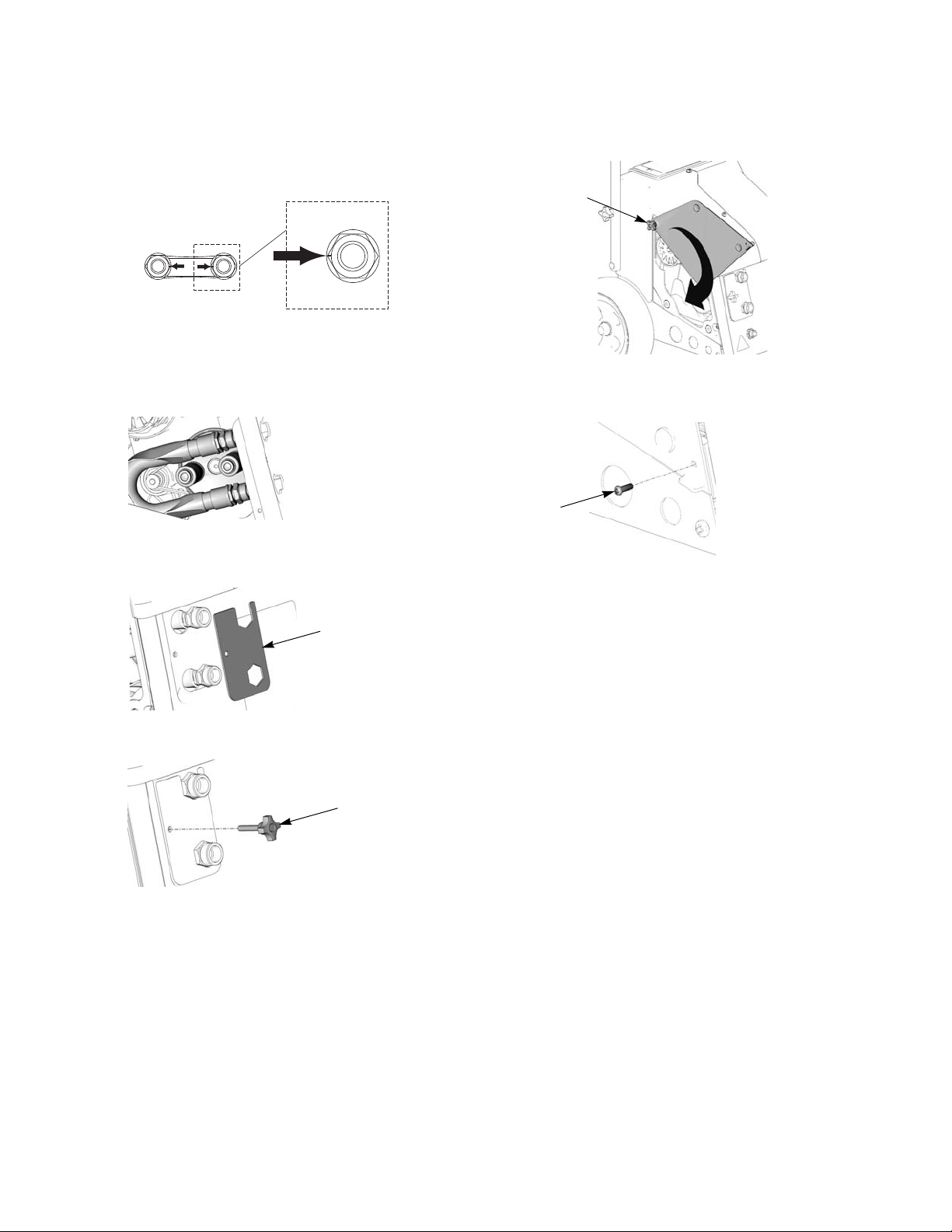
Reassemble
1. Bend hose (16) so colored dots on hose fittings face
each other.
2. Slide new pump hose (16) in from side access
panel. Move pump rollers by hand until or flip power
switch to rotate rollers until they are positioned correctly with pump hose.
3. Replace hose bracket (25) to lock pump hose into
place.
5. Flip side access panel (13) down and tighten knob
(42).
6. Replace and tighten screw (70) from side access
panel.
7. Break in new pump by adding 1 cup of water to
pump and running dry for 3 minutes.
4. Tighten hose bracket knob (42).
311772M 11
Page 12

Compressor
ti2810b
49
ti8941a
ti8878a
26
27
49
ti9013a
ti8877a
29
21
ti8879a
49
ti8952a
ti8951a
Compressor
Use Compressor Repair Kit, 288612.
Disassembly
1. Relieve Pressure, page 6.
2. Unplug sprayer from outlet.
3. Remove Shroud, page 7.
4. Remove RotoFlex
5. Unscrew and remove grounding screw (49) from
compressor.
™
II Pump hose; page 9 or 10.
8. Remove 4 screws (29) and lift bracket (21) off of
compressor.
9. Remove shoulder bolt (49) holding pump roller in
place.
10. Use a wrench to push down on push-to-connect
fittings and pull out all nylon hoses.
6. Use 9/16 in. socket and wrench to remove pivot bolt
(26) and nut (27).
11. Disconnect all electrical wire connectors, see
Wiring Diagram, page 27.
12. Thoroughly clean inside housing, removing dust and
debris.
To service the compressor, remove it from the sprayer
body and place it a vice. Tighten the vice onto the main
7. Unscrew and remove second 1/2 in. grounding
pulley to hold the compressor in place while servicing.
screw (49) from bracket (21).
12 311772M
Page 13

Compressor
ti8940a
ti8950a
49
ti8941a
ti8873a
ti8879a
49
ti8877a
29
21
ti8878a
26
27
80
49
ti9013a
21
Reassembly
1. Carefully position compressor back into sprayer
body. Make sure piston head facing front of sprayer.
2. Replace and tighten grounding screw (49).
6. Replace bracket (21) and tighten 4 screws (29).
7. Replace grounding screw (49) and tighten onto
bracket (21).
8. Replace pivot bolt (26), washers (80) and nut (27).
Use 9/16 in. socket and wrench to tighten into place.
Tighten bolt (26) until spring washers (80) are flattened. Back off nut (27) 1/4 turn. Compressor must
rotate freely with bolt (26) and bracket (21).
3. Reattach air lines to compressor.
4. Reattach 2 wires to compressor see Wiring
Diagram, page 27.
5. Replace air cylinder and tighten shoulder bolt (49) to
lock into place.
9. Replace and tighten second grounding screw (49)
to bracket (21).
10. Replace RotoFlex
™
II Pump hose; page 9 or 10.
11. Replace Shroud, page 7.
311772M 13
Page 14

Piston/Cylinder
ti2810b
100
74
75
76
110
ti8887a
ti8893a
87
77
Piston/Cylinder
Use Piston/Cylinder Repair Kit 288609.
Disassembly
1. Relieve Pressure, page 6.
2. Unplug sprayer from outlet.
3. Remove Shroud, page 7.
4. Remove RotoFlex
5. Remove Compressor, page 12.
6. Remove muffler (110) from head (74) by pulling
straight out by hand.
7. Use 1/2 in. socket to remove three bolts (100) from
head (74).
™
II Pump hose; page 9 or 10.
8. Use flat-blade screwdriver to pry head (74) from top
of valve plate (75) and cylinder (76) from bottom of
valve plate (75).
9. Use 7/32 in. allen wrench to remove hex screw (87)
from piston rod (77).
14 311772M
Page 15

Piston/Cylinder
ti8943a
ti8893a
87
77
100
74
75
76
110
ti8887a
Reassembly
CAUTION
Piston and cylinder come packaged
together. Do NOT let piston and cylinder
come apart. If they do, make sure you
drop the piston down through the top of
the cylinder and tilt the piston as you
pull it through the cylinder. Do NOT
push the piston up from the bottom. You
could easily damage the piston gasket.
1. Replace piston (77) and cylinder (76) and use 7/32
in. allen wrench to tighten hex screw (87) into piston
rod.
3. Replace three bolts (100) and use 1/2 in. socket to
tighten into head (74). Torque all three bolts to 75
in-lb, then torque all bolts again to 210 in-lb.
4. Position muffler (110) as seen below and press onto
head (74) until it snaps into place.
5. Replace Compressor, page 12.
6. Replace RotoFlex
™
II Pump hose; page 9 or 10.
7. Replace Shroud, page 7.
2. Replace valve plate (75) with ribs facing up toward
head.
311772M 15
Page 16

Valve Plate
ti2810b
100
74
75
76
110
ti8887a
Valve Plate
Use Valve Plate Repair Kit 288610.
Disassembly
1. Relieve Pressure, page 6.
2. Unplug sprayer from outlet.
3. Remove Shroud, page 7.
4. Remove RotoFlex
5. Remove Compressor, page 12.
6. Remove muffler (110) from head (74) by pulling
straight out by hand.
7. Use 1/2 in. socket to loosen and remove three bolts
(100) from head (74).
™
II Pump hose; page 9 or 10.
8. Use flat-blade screwdriver to pry head (74) from top
of valve plate (75) and cylinder (76) from bottom of
valve plate (75).
Reassembly
1. Replace valve plate (75) with ribs facing up toward
ribs on head (74).
2. Replace three bolts (100) and use 1/2 in. socket to
tighten into head (74). Torque all three bolts to 75
in-lb, then torque all bolts again to 210 in-lb.
3. Replace Compressor, page 12.
4. Replace RotoFlex
5. Replace Shroud, page 7.
™
II Pump hose; page 9 or 10.
16 311772M
Page 17

Motor
ti2810b
ti8951a
ti8892a
72
ti8891a
105
71
ti9012a
71
ti8893a
87
77
84
ti8894a
Motor
Use Motor Repair Kit 288613.
Disassembly
1. Relieve Pressure, page 6.
2. Unplug sprayer from outlet.
3. Remove Shroud, page 7.
4. Remove RotoFlex
5. Remove Compressor, page 12.
6. Remove compressor from sprayer body and place it
in a vice. Tighten the vice onto the main pulley to
hold the compressor in place while servicing motor.
™
II Pump hose; page 9 or 10.
8. Use a box end wrench to loosen and remove two
mounting bolts (105) on motor (71).
CAUTION
Be careful not to bend or damage the cooling tube
when removing it from the motor.
9. Angle motor (71) and slide motor pulley through
compressor belt to remove motor from compressor.
7. Loosen set screw and remove fan (72).
Compressor belt (84) should be replaced every
time motor is replaced.
10. Use 7/32 in. allen wrench to remove hex screw (87)
from piston rod (77).
11. Remove compressor belt (84).
311772M 17
Page 18

Motor
SQ
ti8890a
71
84
ti8891a
105
71
ti8896a
104
ti8892a
72
Reassembly
1. Angle motor pulley through compressor belt (84)
and pull motor (71) into position.
When replacing motor (71), make sure the
square-shaped hole (SQ) is facing toward the outside of the compressor. This hole will be used to
torque the mounting bolts.
2. Tighten two mounting bolts (105) on motor (71) until
snug, then back 1/8 of a turn.
5. Place compressor back into vice and torque bolts as
described in steps 2 and 3.
6. Replace fan (72) and tighten set screw.
7. Replace Compressor; page 12.
8. Replace RotoFlex
™
II Pump hose; page 9 or 10.
9. Replace Shroud, page 7.
3. Insert torque wrench into square hole (SQ) on motor
and tighten bolts to 130-150 in-lb (this may require
two people; one to torque while the other tightens
mounting bolts). Tighten motor bolts (105).
4. Take compressor out of vice and rotate pump pulley
(104) one full revolution to seat the belt properly.
18 311772M
Page 19

Cooling Tube
ti2810b
ti8886a
101
102
79
ti8952a
ti8944a
Cooling Tube
Use Cooler Repair Kit 288614.
The cooling tube is extremely hot and can cause
serious burns. Allow unit to completely cool before
servicing the cooling tube.
Disassembly
1. Relieve Pressure, page 6.
2. Unplug sprayer from outlet.
3. Remove Shroud, page 7.
6. Use 3/8 in. socket to remove screw (101) and
washer (102) under cooling tube (79).
7. Use wrench to push against fitting (86) and carefully
pull cooling tube (79) out.
8. Use 5/8 in. wrench to unscrew cooling tube fitting.
4. Remove RotoFlex
5. Remove Compressor, page 12.
™
II Pump hose; page 9 or 10.
311772M 19
Page 20

Cooling Tube
ti8942a
ti8895a
79
86
ti9014a
ti8886a
101
102
79
Reassembly
1. Insert new cooling tube fitting and use 5/8 in.
wrench to tighten.
2. Insert cooling tube (79) and push into new fitting
(86). Make sure tube is fully seated.
3. Rotate cooling tube around and insert free end into
push-to-connect fitting. Make sure tube is fully
inserted.
4. Replace screw (101) and washer (102) under cooling tube (79) and use 3/8 in. socket to tighten.
CAUTION
When replacing cooling tube, make sure coil is facing
up when you push the tubing into the fitting. If you
push from any other angle you could bend or damage
the tube.
5. Replace Compressor; page 12.
6. Replace RotoFlex
™
II Pump hose; page 9 or 10.
7. Replace Shroud, page 7.
20 311772M
Page 21

Idler
ti2810b
ti8892a
79
ti8889a
39
106
Idler
Use Idler Repair Kit 288611.
Disassembly
1. Relieve Pressure, page 6.
2. Unplug sprayer from outlet.
3. Remove Shroud, page 7.
4. Remove RotoFlex
5. Remove Compressor, page 12.
6. Remove compressor belt, page 17.
7. Loosen set screw and remove fan (79).
™
II Pump hose; page 9 or 10.
Reassembly
1. Install new compressor belt, page 17.
2. Replace new Idler (106) and tighten screw (39).
3. Replace fan (79) and tighten set screw.
4. Replace Compressor, page 12.
5. Replace RotoFlex
6. Replace Shroud, page 7.
™
II Pump hose; page 9 or 10.
8. Loosen screw (39) and remove Idler (106).
Every time you replace the Idler you should also
replace the compressor belt, page 17.
311772M 21
Page 22

Roller Pulley/Belt
ti2810b
87
73
ti8947a
83
ti8946a
Roller Pulley/Belt
Use Roller Pulley Repair Kit 288616.
Disassembly
1. Relieve Pressure, page 6.
2. Unplug sprayer from outlet.
3. Remove Shroud, page 7.
4. Remove RotoFlex
5. Remove Compressor, page 12.
6. Use 7/32 in. allen wrench to loosen roller mounting
bolt (87) and remove roller pulley (73).
™
II Pump hose; page 9 or 10.
Reassembly
1. Install new compressor belt (83).
2. Loop belt over roller pulley and align roller with bolt
hole.
3. Use 7/32 in. allen wrench to tighten bolt (87) to 20 ±
2 ft-lb.
4. Replace Compressor, page 12.
5. Replace RotoFlex
6. Replace Shroud, page 7.
™
II Pump hose; page 9 or 10.
7. Remove belt (83) and discard.
Every time you replace the roller pulley, you should
also replace the belt.
22 311772M
Page 23

Selector Switch Knob
ti9219a
ti9278a
ti9277a
ti9280a
ti9281a
Selector Switch Knob
Use Knob Repair Kit 288756.
Disassembly
1. Turn selector switch knob clockwise as far as it will
go.
2. Use wrench to remove nut from knob.
Assembly
1. Position new knob to point right (approximately 45°
from vertical) and slide it onto exposed spline.
2. Apply Locktite (1 drop or small amount) to knob nut
and tighten with wrench.
3. Pull knob straight off from sprayer.
Once knob has been removed, don’t move the
exposed spline. If it is moved, use your fingers to
turn it clockwise as far as it will go for a tight fit prior
to reassembly of knob. This will properly align knob
to spline.
311772M 23
Page 24

Regulator Valve
ti8952a
ti9279a
ti9282a
ti9275a
ti9279a
Regulator Valve
Use Regulator Repair Kit 288757.
Disassembly
1. Remove Knob, page 23.
2. Remove Shroud, page 7.
3. Use wrench to push against fitting (86) and carefully
pull cooling tube (79) out.
4. Use phillips screwdriver to remove two screws.
Assembly
1. Replace new regulator valve and feed through 3
holes on side of sprayer.
2. Reattach two air lines.
5. Remove old regulator valve.
3. Replace two screws and tighten with phillips screwdriver.
4. Replace Knob, page 23.
5. Replace Shroud, page 7.
24 311772M
Page 25

Troubleshooting
Troubleshooting
Problem Cause Solution
Sprayer won’t run Power switch not on Turn switch on.
No power at wall outlet Check outlet by plugging in another
appliance. If appliance does not
work, try another outlet.
Wrong size generator Use a 3500 watt or larger generator.
Refer to Generator Requirements,
page 6.
Breaker tripped Reset breaker.
Pump won’t pump material Air lock Open air valve on gun.
Selector switch in wrong position Move selector switch to correct posi-
tion for application.
Mix too thick Add water to thin material. Use Mate-
rial Thickness Gauge.
Loose fittings Check and retighten all fittings.
Plugged gun Relieve Pressure, page 6. Remove
gun from hose. Clean gun.
Pump hose worn out Replace hose. Recommended hose
replacement - once every year.
Pump cold Move pump to warm room and allow
it to warm up or run hot water through
sprayer.
Material runs out of bottom of sprayer Pump hose worn out Replace hose.
Loose fittings Check and retighten all fittings.
No air from compressor Gun air valve closed Open gun air valve.
Low voltage Check extension cord length and
gauge. Replace if different than recommended. Refer to Grounding and
Electrical Requirements, page 6.
Gun needle plugged Clean needle and retry.
Worn compressor Replace compressor. Contact a qual-
ified Graco Service Center.
Lines not connected Check all quick disconnect connec-
tions to gun and hoses.
Damaged hose Replace hose.
311772M 25
Page 26

Troubleshooting
Problem Cause Solution
Speed of application slow or slower Material too thick Thin material.
Nozzle too small Change nozzles to a larger size. See
Operation manual 311768.
Too much air being used. Partially close gun air valve to reduce
air flow.
Pump hose worn Replace hose.
Plugged or dirty gun Relieve Pressure, page 6. Clean
gun.
Kinked hose Unkink hose.
Gun adjustment set too low Increase flow adjustment with flow
adjustment nut.
Too many items on same circuit Unplug other items from circuit.
Extension cord too long or wrong
gauge
Use a different extension cord. Refer
to Grounding and Electric Requirements, page 6.
Intermittent flow/sputtering Hopper connection not tight Check gasket. TIghten connection.
Debris in system Clean system.
Quick disconnect does not stay connected.
Dirty or corroded fitting Clean thoroughly. Soak in oil. Apply a
few drops of light oil.
Gun will not shut off Worn nozzle or needle. Relieve Pressure, page 6. Replace
worn parts.
Debris in needle passage Relieve Pressure, page 6. Clean.
Fluid leaking at Flow Adjustment Nut Damaged seal. Relieve Pressure, page 6. Replace
seal.
Fluid leaking out of either plug Missing or damaged o-rings Relieve Pressure, page 6. Replace
o-rings.
Gun damaged Replace gun.
Needle adjustment won’t adjust Dirty threads Clean threads.
Nozzle not on gun Put nozzle on gun.
26 311772M
Page 27

Wiring Diagram
40
19
34
21
49
Switch
Motor
White Wire
Black Wire
Power Cord
Green Wire (GND)
ti8937a
49
Cylinder
Air Valve
Manifold on Compressor
Compressor
Air Outlet
38
84
15
34
ti8936a
55
59
Relief Valve
53
53
68
66
81
Gauge
Regulator
69
RTX 1250RTX 900
Cylinder
Air Valve
Manifold on Compressor
Compressor
Air Outlet
Relief Valve
38
56
59
55
34
15
84
ti9232a
41
Wiring Diagram
Air Diagram
311772M 27
Page 28

Parts Drawing
23
42
43
2
7
25
42
10
11
40
31
30
14
12
63
5
62
32
15
ti8901c
14
8
62
47
37
22
46
29
71
28
(RTX 900)
47
(RTX 900)
70
76
82
77
79
(RTX 900)
(RTX 900)
83
(RTX 1250)
45
85
85
85
Parts Drawing
Models 254974 and 254975
28 311772M
Page 29

Parts Drawing
6
19
61
3
4
16
38
21
26
29
29
35
50
59
51
54
15
29
ti8902b
52
27
34
36
49
•
•
•
RTX 1250 Only
66
33
65
69
80
49
•
57
RTX 1250 Only
60
31
31
1
68
58
78
41
Parts Drawing
Models 254974 and 254975
311772M 29
Page 30

Parts List
Parts List
Models 254974
Ref. Part Description Qty.
1 288386 PLATE, front, RTX 1
2 15J600 TOOLBOX 1
3 15H069 SUPPORT, hopper, RTX 1
4 288384 FRAME, back, RTX (painted) 1
5 288350 COVER, shroud; RTX 900 1
6 277319 SHIELD, bottom 1
7 288351 COVER, shroud; RTX 900 1
8 15J670 AXLE 1
10 115095 WHEEL, 9 in. 2
11 112612 CAP, hub 2
12 288314 HANDLE 1
14 15H641 KNOB 2
15 288336 FITTING, bulkhead, assembly 1
16 288623 HOSE, pump, (Roto-Flex
19 120660 SWITCH 1
21 15H910 BRACKET, pump, RTX 1
22 15C090 GAUGE, thickness, fluid 1
23 288093 HOPPER 1
25 288515 PLATE, support, RTX (painted) 1
26 105240 SCREW, cap hex hd 1
27 113981 NUT, lock, high tensile 1
28 120444 SCREW 1
29 117630 SCREW, torx, tri lob 6
30 117633 SCREW, slot hex wash hd 2
31 120771 SCREW, mach, pnh 5
32 15H605 HANGER 2
34 288856 COMPRESSOR, pump assembly 1
35 120236 SCREW, shoulder 1
36 120731 WASHER, flat 1
38 289591 CYLINDER, RTX 1
40 15J758 CORD, power 1
41 113318 FITTING, elbow, plug-in 1
42 15J862 KNOB, 1/4-20, 4 prong 1
™
)1
Ref. Part Description Qty.
43 15D561 COVER, tool tray 1
45 288628 GUN, spray (for use w/ hopper) 1
46 234147 HOSE 1
47 120759 PAD, non-slip, foot 1
48 103473 STRAP, tie, wire 1
49 115498 SCREW, mach, slot hex wash hd 2
50 104227 NUT, lock 1
51 15H841 LABEL, warning 1
52 15K616 LABEL, caution 1
53 120694 TUBE, air 1
54 15H868 LABEL, instruction 1
55 120694 TUBE, air, .250 1
56 120569 TUBE, air, .250 1
58 288756 KIT, repair, knob 1
59 288757 KIT, repair, regulator
(includes 59, 60)
60 120744 SCREW, mach, pnh 2
61 120637 NUT, acorn 1
62 15C753 SCREW, machine, hex
washer head
63 111831 SCREW, cap, skt, button hd 1
71 15H912 GUARD, burp 1
76 15K323 LABEL, hopper, RTX 900 1
77 15K329 LABEL, control, RTX 900 1
78 15K335 LABEL, front, RTX 900 1
79 15K338 LABEL, shroud, RTX 900 1
80 120215 WASHER, belleville 2
84 120567 TUBE, air, .250 OD 1
85 115099 GASKET 3
Additional warning labels are available at no cost.
1
2
30 311772M
Page 31

Parts List
Parts List
Models 254975
Ref Part Description Qty
1 288386 PLATE, front, RTX 1
2 15J600 TOOLBOX 1
3 15H069 SUPPORT, hopper, RTX 1
4 288384 FRAME, back, RTX (painted) 1
5 288650 COVER, shroud 1
6 277319 SHIELD, bottom 1
7 288382 COVER, shroud (painted) 1
8 15J671 AXLE, RTX 1250 1
10 115094 WHEEL, 10 2
11 112612 CAP, hub 2
12 288314 HANDLE, RTX (painted) 1
14 15H641 KNOB 2
15 288336 FITTING, bulkhead, assembly 1
16 288623 HOSE, coupled 1
19 120660 SWITCH 1
21 15H910 BRACKET, pump, RTX 1
22 15C090 GAUGE, thickness, fluid 1
23 288265 HOPPER 1
25 288515 PLATE, support, RTX (painted) 1
26 105240 SCREW, cap hex hd 1
27 113981 NUT, lock, high tensile 1
29 117630 SCREW, torx, tri lob 6
30 117633 SCREW, slot hex wash hd 3
31 120771 SCREW 5
32 15H605 HANGER 2
33 115494 SCREW, mach, phillips, pan hd 3
34 288651 COMPRESSOR, pump assembly 1
35 120236 SCREW, shoulder 1
36 120731 WASHER, flat 1
37 120411 RIVET, blind 3
38 289591 CYLINDER, RTX 1
40 15J758 CORD, power 1
41 113318 FITTING, elbow, plug-in 1
42 15J862 KNOB, 1/4-20, 4 prong 3
43 15D561 COVER, tool tray 1
46 234147 HOSE 1
Ref Part Description Qty
48 103473 STRAP, tie, wire 1
47 15K049 ISOLATOR, foot 1
49 115498 SCREW, mach, slot hex wash hd 2
50 104227 NUT, lock 1
51 15H841 LABEL, warning 1
52 15K616 LABEL, caution 1
53 120694 TUBE, air 2
54 15H868 LABEL, instruction 1
55 120568 TUBE, air, .250 OD 1
57 198492 LABEL, warning 1
58 288756 KIT, repair, knob (includes 58, 61) 1
59 288757 KIT, repair, regulator
(includes 59, 60)
60 120744 SCREW, mach, pnh 2
61 120637 NUT, acorn 1
62 15C753 SCREW, machine, hex washer head 2
63 111831 SCREW, cap, skt, button hd 1
65 115244 NUT, regulator 1
66 117694 REGULATOR, air, 1/8 in. npt 1
68 120665 GAUGE, pressure 1
69 120653 FITTING, elbow 1
70 120994 SCREW, mach, pnh 1
71 15H912 GUARD, burp 1
76 15K322 LABEL, hopper, RTX1250 1
78 15K334 LABEL, front, RTX 1250 1
80 120215 WASHER 2
81 TUBE, air, .250 OD 1
82 15K328 LABEL, control, RTX1250 1
83 15K364 LABEL, side panel, RTX1250 1
84 120567 TUBE, air, .250 OD 1
85 115099 GASKET 3
Additional warning labels available at no cost.
1
311772M 31
Page 32

Parts Drawing and List
110
100
74
75
71
108
109
106
105
77
73
87
83
84
87
101
102
72
79
ti8903a
86
76
117
Compressor 288856 & 288651
Parts Drawing and List
Ref. Part Description Qty.
288856 KIT, repair, compressor, complete
(includes all items) RTX 900
288651 KIT, repair, compressor, complete
(includes all items) RTX 1250
288612 KIT, repair, compressor, rebuild
(includes 100, 74, 86, 75, 76,
77, 87)
71 288613 KIT, repair, motor, universal, 120v
(includes 71, 72, 84, 105, 106)
72 120466 FAN, repair, motor 1
73 288616 KIT, repair, pulley, w/rollers
(includes 73, 83, 87)
74 288746 KIT, repair, head, compressor
(includes 74, 75)
75 288610 KIT, repair, plate, valve 1
76 CYLINDER, compressor 1
77 288609 KIT, repair, piston/cylinder
(includes 75, 76, 77, 87)
Ref. Part Description Qty.
79 288614 KIT, repair, cooler
(includes 79, 86)
83 120234 BELT 1
84 120233 BELT 1
86 120245 FITTING 1
87 120204 SCREW, mach, hex flat head 2
95 120593 SCREW, mach, torx pan hd 3
100 120229 SCREW, hex flange 3
1
101 119872 SCREW, shoulder 1
102 120659 WASHER, flat 1
105 260215 SCREW, hex hd 2
1
106 100023 WASHER, flat 2
108 288611 KIT, repair, idler (includes 108, 84) 1
1
109 104272 SCREW, cap, sch 1
110 15H940 FITTING 1
117 120617 VALVE, pressure relief, RTX 1250 1
117 120251 VALVE, pressure relief, RTX 900 1
1
1
32 311772M
Page 33

Technical Data
Technical Data
Main unit power requirements 120 Vac, 60 Hz, 15A, 1 phase
Maximum fluid working pressure 70 psi, (4.9 bar)
Maximum air working pressure 50 psi, (3.5 bar)
Compressor specifications Universal motor thermally protected, oil-less
Compressor air displacement 4.0 scfm at 45 psi
Generator required 3500W minimum
Electric Motor Universal AC 14 Amp 1.5 Hp
Power Cord 16 AWG, 3-wire, 25 ft
Material hopper capacity Model 254974: 8 gallons
Model 254975: 10 gallons
Gun material hopper: 3/4 gallon
Maximum delivery with texture RTX 900 - 0.9 gpm (3.4 lpm)
RTX 1250 - 1.25 gpm (4.7 lpm)
Dimensions: RTX 900
Length 23 in. (584 mm) with handle
Width 18 in. (456 mm)
Height 40 in. (1016 mm)
Weight (includes hose and gun) 60 lb (27.2 kg)
Dimensions: RTX 1250
Length 24 in. (609 mm) with handle
Width 20 in. (508 mm)
Height 41 in. (1041 mm)
Weight (includes hose and gun) 65 lb (29.5 kg)
Wetted parts brass, aluminum, plastic
Sound data
Sound pressure level* 83.2 dB(A)
Sound power level** 97.5 dB(A)
Storage Temperature Range 35°F - 160°F (1.6°C - 71°C)
Operating Temperature Range 40°F - 115°F (4°C - 46°C)
Gun:
Maximum Working Pressure 70 psi (4.9 bar)
Air Maximum Working Pressure 100 psi (6.895 bar)
CFM Rating 3.5 - 11 CFM
Weight 1.1 lb (500 g)
* Measured while spraying at 1 m
** Measured per ISO-3744
311772M 33
Page 34

Graco Standard Warranty
Graco warrants all equipment referenced in this document which is manufactured by Graco and bearing its name to be free from defects in
material and workmanship on the date of sale the original purchaser for use. With the exception of any special, extended, or limited warranty
published by Graco, Graco will, for a period of twelve months from the date of sale, repair or replace any part of the equipment determined by
Graco to be defective. This warranty applies only when the equipment is installed, operated and maintained in accordance with Graco’s written
recommendations.
Graco warrants all equipment referenced in this document which is manufactured by Graco and bearing its name to be free from defects in
material and workmanship on the date of sale by an authorized Graco distributor to the original purchaser for use. With the exception of any
special, extended, or limited warranty published by Graco, Graco will, for a period of twelve months from the date of sale, repair or replace any
part of the equipment determined by Graco to be defective. This warranty applies only when the equipment is installed, operated and maintained
in accordance with Graco’s written recommendations.
This warranty does not cover, and Graco shall not be liable for general wear and tear, or any malfunction, damage or wear caused by faulty
installation, misapplication, abrasion, corrosion, inadequate or improper maintenance, negligence, accident, tampering, or substitution of
non-Graco component parts. Nor shall Graco be liable for malfunction, damage or wear caused by the incompatibility of Graco equipment with
structures, accessories, equipment or materials not supplied by Graco, or the improper design, manufacture, installation, operation or
maintenance of structures, accessories, equipment or materials not supplied by Graco.
This warranty is conditioned upon the prepaid return of the equipment claimed to be defective to an authorized Graco distributor for verification of
the claimed defect. If the claimed defect is verified, Graco will repair or replace free of charge any defective parts. The equipment will be returned
to the original purchaser transportation prepaid. If inspection of the equipment does not disclose any defect in material or workmanship, repairs
will be made at a reasonable charge, which charges may include the costs of parts, labor, and transportation.
THIS WARRANTY IS EXCLUSIVE, AND IS IN LIEU OF ANY OTHER WARRANTIES, EXPRESS OR IMPLIED, INCLUDING BUT NOT
LIMITED TO WARRANTY OF MERCHANTABILITY OR WARRANTY OF FITNESS FOR A PARTICULAR PURPOSE.
Graco’s sole obligation and buyer’s sole remedy for any breach of warranty shall be as set forth above. The buyer agrees that no other remedy
(including, but not limited to, incidental or consequential damages for lost profits, lost sales, injury to person or property, or any other incidental or
consequential loss) shall be available. Any action for breach of warranty must be brought within two (2) years of the date of sale.
GRACO MAKES NO WARRANTY, AND DISCLAIMS ALL IMPLIED WARRANTIES OF MERCHANTABILITY AND FITNESS FOR A
PARTICULAR PURPOSE, IN CONNECTION WITH ACCESSORIES, EQUIPMENT, MATERIALS OR COMPONENTS SOLD BUT NOT
MANUFACTURED BY GRACO. These items sold, but not manufactured by Graco (such as electric motors, switches, hose, etc.), are subject to
the warranty, if any, of their manufacturer. Graco will provide purchaser with reasonable assistance in making any claim for breach of these
warranties.
In no event will Graco be liable for indirect, incidental, special or consequential damages resulting from Graco supplying equipment hereunder, or
the furnishing, performance, or use of any products or other goods sold hereto, whether due to a breach of contract, breach of warranty, the
negligence of Graco, or otherwise.
FOR GRACO CANADA CUSTOMERS
The Parties acknowledge that they have required that the present document, as well as all documents, notices and legal proceedings entered into,
given or instituted pursuant hereto or relating directly or indirectly hereto, be drawn up in English. Les parties reconnaissent avoir convenu que la
rédaction du présente document sera en Anglais, ainsi que tous documents, avis et procédures judiciaires exécutés, donnés ou intentés, à la suite
de ou en rapport, directement ou indirectement, avec les procédures concernées.
Graco Information
For the latest information about Graco products, visit www.graco.com.
For patent information, see www.graco.com/patents.
TO PLACE AN ORDER, contact your Graco distributor or call 1-800-690-2894 to identify the nearest distributor.
All written and visual data contained in this document reflects the latest product information available at the time of publication.
GRACO INC. AND SUBSIDIARIES • P.O. BOX 1441 • MINNEAPOLIS MN 55440-1441 • USA
Copyright 2007, Graco Inc. All Graco manufacturing locations are registered to ISO 9001.
Graco reserves the right to make changes at any time without notice.
For patent information, see www.graco.com/patents.
Original instructions. This manual contains English. MM 311770
Graco Headquarters: Minneapolis
International Offices: Belgium, China, Japan, Korea
www.graco.com
Revised P August 2014
 Loading...