

Page 1
Instructions–Parts List
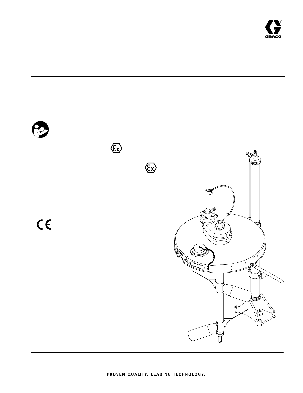
HEAVY-DUTY STAINLESS STEEL
Drum Agitator
Heavy–duty, back–geared agitator for mixing and maintaining
suspension of industrial coatings stored in 55–gallon drums. For
professional use only.
100 psi (0.7 MPa, 7 bar) Maximum Air Input Pressure
Important Safety Instructions
Read all warnings and instructions
in this manual. Save these instructions.
308609P
EN
*Model 238157, Series C
Back-Geared, Air-Powered Agitator
II 1/2 G T6
ITS03ATEX11226
*Models 24C293, 24C522, Series B
Back-Geared, Drum Mounted, Air-Powered Agitator
*Model 231414, Series A
Siphon Agitator Package
*Model 231413, Series A
Non-Siphon Agitator Package
*
0359
Model 238250, Series A
Siphon Tube Kit
Model 240209, Series C
Back-Geared, Air-Powered Siphon Agitator
Table of Contents
Warnings 2. . . . . . . . . . . . . . . . . . . . . . . . . . . . . . . . . . . . . .
Installation 4. . . . . . . . . . . . . . . . . . . . . . . . . . . . . . . . . . . . .
Operation 9. . . . . . . . . . . . . . . . . . . . . . . . . . . . . . . . . . . . .
Service 10. . . . . . . . . . . . . . . . . . . . . . . . . . . . . . . . . . . . . .
Parts 14. . . . . . . . . . . . . . . . . . . . . . . . . . . . . . . . . . . . . . . .
Technical Data 19. . . . . . . . . . . . . . . . . . . . . . . . . . . . . . .
Dimensional Drawings 19. . . . . . . . . . . . . . . . . . . . . . . . .
Mounting Hole Layout 21. . . . . . . . . . . . . . . . . . . . . . . . . .
Graco Standard Warranty 22. . . . . . . . . . . . . . . . . . . . . .
Graco Information 22. . . . . . . . . . . . . . . . . . . . . . . . . . . . .
II 1/2 G T6
ITS03ATEX11226
Model 231414 shown
05771B
Page 2
Symbols
Warning Symbol
WARNING
This symbol alerts you to the possibility of serious
injury or death if you do not follow the instructions.
WARNING
EQUIPMENT MISUSE HAZARD
Equipment misuse can cause the equipment to rupture or malfunction and result in serious injury.
INSTRUCTIONS
This equipment is for professional use only.
Read all instruction manuals, tags, and labels before operating the equipment.
Use the equipment only for its intended purpose. If you are not sure, call your Graco distributor.
Do not alter or modify this equipment.
Check equipment daily. Repair or replace worn or damaged parts immediately.
Caution Symbol
CAUTION
This symbol alerts you to the possibility of damage to
or destruction of equipment if you do not follow the
instructions.
Do not exceed the maximum working pressure of the lowest rated component in your system. This
equipment has a 100 psi (0.7 MPa, 7 bar) maximum working pressure.
Use fluids and solvents that are compatible with the equipment wetted parts. Refer to the
Technical Data section of all equipment manuals. Read the fluid and solvent manufacturer’s
warnings.
Always wear protective eyewear, gloves, clothing, and respirator as recommended by the fluid and
solvent manufacturer.
Comply with all applicable local, state, and national fire, electrical, and safety regulations.
2 308609
Page 3
WARNING
FIRE AND EXPLOSION HAZARD
Improper grounding, poor ventilation, open flames, or sparks can cause a hazardous condition and
result in a fire or explosion and serious injury.
Ground all equipment. Refer to Grounding on page 4.
If there is any static sparking or you feel an electric shock while using this equipment, shut off the
agitator immediately. Do not use the equipment until you identify and correct the problem.
Do not use 1,1,1–trichloroethane, methylene chloride, other halogenated hydrocarbon solvents, or
fluids containing such solvents in aluminum pumps. Such use could result in a serious chemical
reaction, with the possibility of explosion.
Do not use kerosene or other flammable solvents or combustible gases to flush the unit.
Provide fresh air ventilation to avoid the buildup of flammable fumes from solvents or the fluid
being dispensed.
Keep the dispensing area free of debris, including solvent, rags, and gasoline.
Do not smoke in the dispensing area.
Keep a fire extinguisher in the work area.
MOVING PARTS HAZARD
Moving parts, such as the rotating blades of the agitator, can pinch or amputate your fingers or other
body parts and can cause splashing in the eyes or on the skin.
Keep clear of all moving parts when starting or operating the agitator.
Always shut off the agitator and disconnect the air line before you remove the agitator from the
drum or check or repair any part of the agitator.
HAZARDOUS VAPORS
Hazardous fluids or toxic fumes can cause serious injury or death if splashed in the eyes or on the
skin, swallowed, or inhaled. When flushing the air motor, keep your face away from the exhaust port.
3308609
Page 4
WARNING
e
Installation
Assembling and Positioning the Agitator
FIRE AND EXPLOSION HAZARD
Always maintain a minimum of 1 in. clearanc
between rotating agitator parts and container
to prevent sparks from contact.
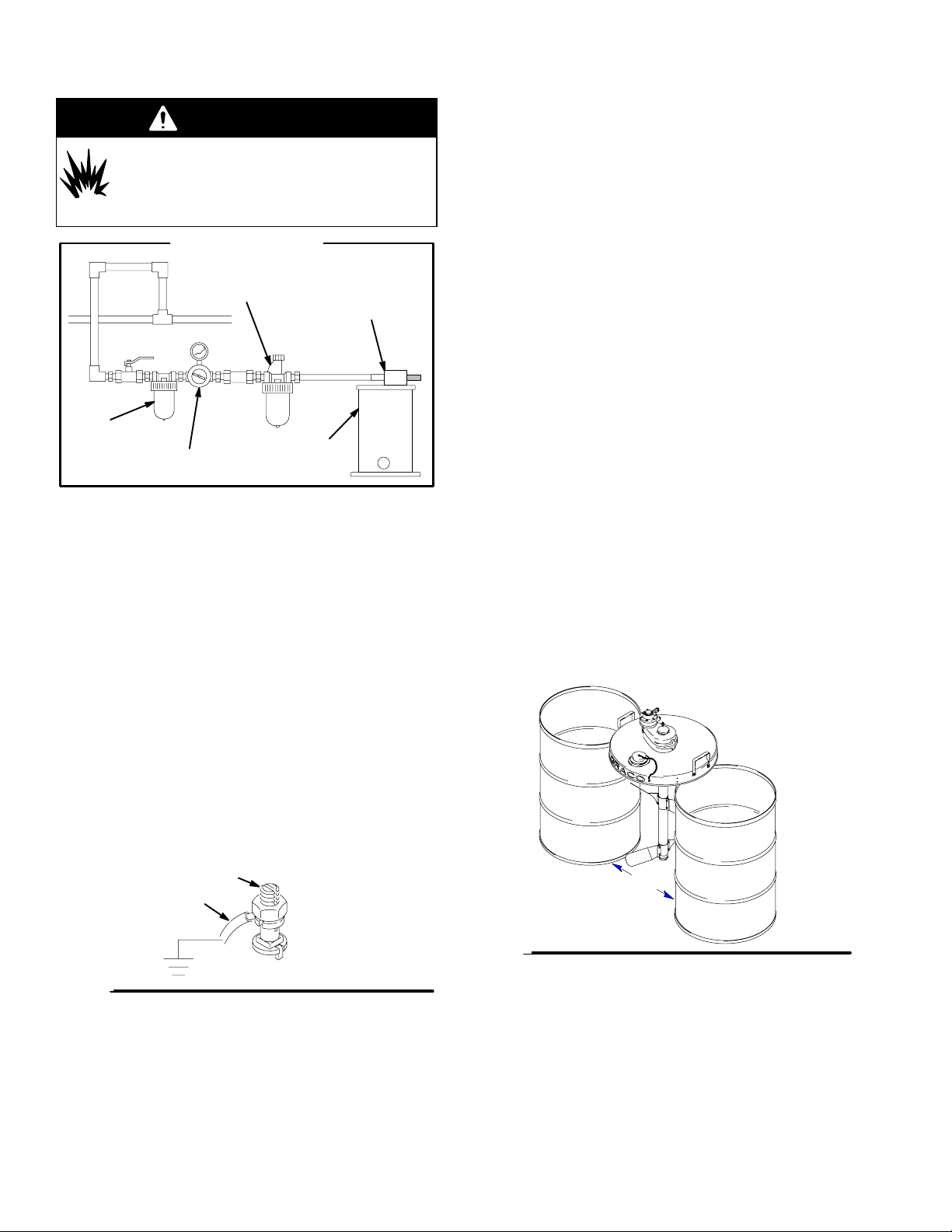
Typical Installation
air line lubricator
agitator motor
air line filter
air regulator
and gauge
NOTE: Reference numbers and letters in parentheses
refer to the callouts in the figures and in the Parts
Drawings.
mix tank
(reference only)
Grounding
Proper grounding is an essential part of maintaining a
safe system.
With an Elevator
Mount the drum cover as described in manual 306287.
The elevator must be in the down position when you
do any work on the elevator, agitator, or drum cover
assembly. Do not go under the elevator when it is
raised. Proceed to step 1 in With or Without an
Elevator.
Without an Elevator
If your system does not have an elevator, you should
install the Handles Kit to facilitate handling the drum
cover and agitator. Two people are needed to safely lift
and move the drum cover and agitator. To order the
Handles Kit, order Part No. 237524.
Place two standard 55 U.S. gallon (45 Imperial gallon)
barrels 14 in. (approximately 36 cm) apart, and center
the drum cover on the barrels with the Graco logo
centered and facing you, as shown in Fig. 2. Proceed
to step 1 in With or Without an Elevator.
To reduce the risk of static sparking, the mounting
cover and all electrically conductive objects or devices
in the dispensing area must be properly grounded.
Check your local electrical code for detailed grounding
instructions for your area and type of equipment.
To ground the agitator, connect one end of the
ground wire (A) to the ground connector (B) on the
agitator. See Fig.1. Connect the other end of the
ground wire to a true earth ground.
For an additional ground wire and clamp, order
Part No. 237569.
B
A
Fig. 1
Fig. 2
Assembling and Positioning
Agitator Without an Elevator
14 in. (36 cm)
05734
4 308609
Page 5

Installation
With or Without an Elevator
1. Slide the agitator shaft through the large hole in
the center of the drum cover (29).
2. Rotate the agitator so that the air motor is to the
left of the shaft, as shown in Fig. 2, which will align
the three tapped holes in the bottom of the agitator
with the three through holes in the drum cover.
3. Thread the three hex head screws (25) up through
the drum cover and into the agitator, and torque
them to 75 in-lb (8.4 N-m).
4. Assemble one pair of agitator blades (28) so that
the four through holes in the blade halves are lined
up (see Parts Drawing for blade orientation).
5. Push four cap screws (31) through the four holes
in the blades, and start the lock nuts (32) onto the
cap screws.
For in–drum heavy duty back geared agitator
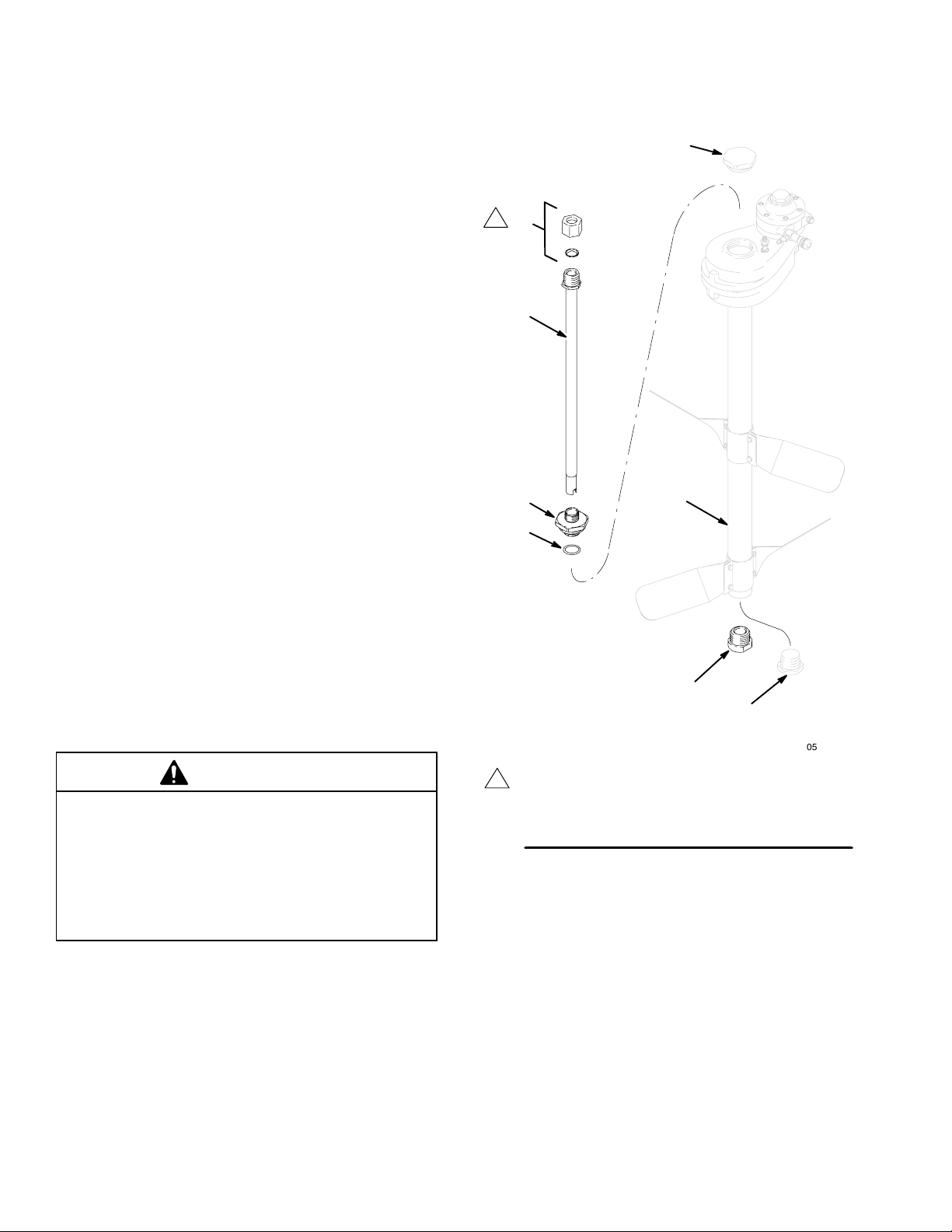
1. Determine which size adaptor nut (20) is needed.
The adaptor nuts in the kit are double–sided
meaning that each adaptor nut will cover two
agitator shaft sizes. Select the size you need by
placing the adaptors onto the built in agitator shaft
in the drum. The one you should use is the smallest one that will fit. There should only be a small
amount of slop between the adaptor nut and the
shaft.
2. Thread the adaptor into the gearbox output shaft
(6) with the side you are going to use pointed
down. Tighten it down using the wrench flats.
3. Place the threaded bung adaptor (34) onto the
gearbox and align the bolt holes.
6. Slide the loose blade assembly up the shaft, and
position it approximately 13 in. (33 cm) from the
bottom of the shaft.
7. Tighten the four lock nuts (32) evenly to draw the
blades together until they are tight on the shaft.
Torque the locknuts to 50 to 55 in-lb (5.6 to 6.2
N-m). A gap will remain between the blade halves.
8. Repeat steps 4 and 5 with the second pair of
agitator blades.
9. Position the second blade assembly near the
bottom end of the shaft, but not on the bottom
plug (20).
10. Rotate the lower blade assembly so that it is
oriented 90 degrees relative to the upper blade
assembly, and torque the lock nuts (32) to 50 to 55
in-lb (5.6 to 6.2 Nm). A gap will remain between
the blade halves.
4. Thread the three bolts (28) into the gear box and
torque to 10 ft–lbs (13.5 Nm).
5. Align the adaptor nut to engage the built–in shaft in
the 55–gallon drum.
6. Slowly screw the unit onto the threads on the
center bung fitting of the 55–gallon drum.
7. Torque the unit to 45 ft–lb (61 Nm). Place the
adaptor of the torque wrench on the top of the unit
to torque.
5308609
Page 6
Installing the Siphon Kit
Installation
See the Siphon Kit, Model 238250, Parts List on page
15.
1. Remove the top plug (5) and the bottom plug (20).
2. Replace the bottom plug (20) with the plain bearing
(53), and tighten the bearing with a wrench.
3. Work the PTFE o-ring (54) onto the siphon tube
retainer (51), and press it into the o-ring groove.
4. Replace the top plug (5) with the siphon tube
retainer (51). Leave the retaining nut (52) on the
siphon tube retainer, but make sure it is not tightened. Tighten the siphon tube retainer into the top
of the agitator housing with a wrench.
5. Slide the siphon tube (50) down through the retaining nut (52), siphon tube retainer (51), and agitator
shaft (6) until the siphon tube touches the bottom
of the drum. Raise the siphon tube approximately
1/4 in. (approximately 6 mm) so that it does not
touch the bottom of the drum. Hold the siphon tube
at this height with one hand, and tighten the retaining nut with the other hand (hand-tight is enough to
hold the siphon tube in place).
5
1
52
50
51
54
6
53
20
CAUTION
Barrel Heights Vary.
Loosen the retaining nut on the siphon tube retainer
before you raise the drum cover. If you do not loosen
the retaining nut, the siphon tube may make contact
with the bottom of the barrel when you lower the
drum cover onto a new barrel, which could damage
the siphon tube or the barrel.
6 308609
Make sure the center tabs on the
1
retaining nut ferrule point down.
Fig. 3
05736B
Page 7

Installation
Return Tube Kit 238884 (Accessory)
Return Tube Kit 238884 is available as an accessory.
The kit must be ordered separately. Refer to the sheet
packed with the kit for installation instructions.
Air Requirements
For continuous use, the 3/4 HP (550 W) agitator air
motor typically requires 3 to 4 cfm (0.09 to 0.12
m3/min) air supply.
Air Line Accessories
Attach a quick disconnect air line fitting and coupler, or
attach a ball valve for main air shut–off to the air line.
To order the 1/8” npt(m) air line fitting, order Part No.
169969. To order the coupler, order Part No. 208536.
Install an air line filter to remove harmful dirt and
moisture from the air supply. To order an air line filter,
order Part. No. 106148 (3.8” npt, 20–micron element, 5
oz. Bowl, without gauge).
CAUTION
Not lubricating the air motor will cause air motor failure.
Downstream from the filter, install an air line lubricator
for automatic air motor lubrication. Set the lubricator
feed rate at 1 drop of oil per minute for high speed or
continuous duty usage. Do not overfeed oil or exhaust
air may become contaminated. To manually lubricate
the air motor, see Lubricating the Air Motor on page
10. To order a 3/8” npt air line lubricator, order Part No.
214847.
7308609
Page 8

Notes
8 308609
Page 9

Operation
WARNING
MOVING PARTS HAZARD
To reduce the risk of serious injury, including cuts, amputation of fingers by the agitator blades, and
splashing in the eyes or on the skin, always shut off the agitator (disconnect the air line from the
agitator) before you raise, check, or repair the agitator.
Startup
1. Make sure the needle valve (23) is closed.
2. Turn on the air supply, and connect the air line
coupler.
3. Using the needle valve (23) to adjust the agitator
speed, gradually increase the speed until you can
see through the inspection port movement in the
surface of the liquid, but do not increase the agitator speed enough to create a vortex in the surface
of the liquid. If the surface begins to vortex,
decrease the agitator speed to prevent air entrainment.
NOTE: Always maintain moderate agitator speed,
which is approximately 50 rpm of the agitator blades.
Excessive agitator speed may cause vibration, foaming of fluid, and increased wear on parts. Always
agitate fluid thoroughly before supplying it to the dispensing equipment. Continue agitating fluid while the
dispensing equipment is being supplied.
Shutdown
To stop the agitator, close off the air supply with the
needle valve (23), or disconnect the air line coupler.
CAUTION
Keep the agitator upright. Do not lay it on its side or
upside down, or liquid may flow down the shaft and
into the gear reducer area.
9308609
Page 10

Service
Flushing the Air Motor
WARNING
FIRE AND EXPLOSION HAZARD
Do not use kerosene or other flammable
solvents to flush the air motor. Flushing
with flammable solvents could cause fire or
explosion and result in serious injury or property
damage.
WARNING
HAZARDOUS VAPORS
Hazardous fluids or toxic fumes can
cause serious injury or death if splashed
in the eyes or on the skin, swallowed, or
inhaled. When flushing the air motor, keep your
face away from the exhaust port, and wear the
appropriate protective clothing, gloves, eyewear,
and respirator.
If the air motor (1) is sluggish or inefficient, follow this
procedure in a well ventilated area.
If an air line lubricator is not installed, the air motor
must be manually lubricated every 8 hours. Lubricate
the agitator air motor by placing 10–20 drops of SAE
#10 light oil in the motor’s air inlet. Run the agitator for
about 30 seconds.
Additional Air Motor Service
If the air motor vanes need to be replaced, or if foreign
material is present in the motor chamber, an experienced mechanic may remove the end plate opposite
the drive shaft end of the air motor. Do not pry with a
screwdriver; it will dent the surface of the plate and
body and cause leaks. Use a puller tool, which will
remove the end plate while maintaining the position of
the shaft.
New vanes should have the edges with cut corners
pointing toward the bottom of the vane slot.
To order an Air Motor Repair Kit, order Part No.
207335.
1. Disconnect the air line and muffler (22). See the
Parts Drawing on page 14.
2. Add several teaspoons of non-flammable solvent,
or spray the solvent directly into the male quickdisconnect coupler (24).
NOTE: The recommended solvent for air motors
and lubricated pumps is Gast Flushing Solvent
(Part No. AH255 or AH255A) or Penetone Inhibisol Safety Solvent.
3. Reconnect the air line, and slowly increase the air
pressure until there is no trace of solvent in the
exhaust air.
4. Reconnect the muffler (22).
5. Re-lubricate the motor with a squirt of lightweight
oil into the male quick-disconnect coupler (24).
Lubricating the Air Motor
CAUTION
Not lubricating the air motor will cause air motor failure.
10 308609
Page 11

Service
Cleaning the Agitator Shaft and Seal
CAUTION
Keep the agitator upright. Do not lay it on its side or
upside down, or liquid may flow down the shaft and
into the gear reducer area.
If any material is on the shaft (6) within 1/2 in. (13 mm)
of the housing (13), it must be removed to prevent
damage to the bearing seal (14*). If the flexible lips on
the bearing seal are torn or worn such that they do not
make contact all the way around the shaft, the seal
must be replaced. A worn seal may allow foreign material into the bearing and cause premature failure. See
Servicing the Gear Reducer on page 11 for instructions on getting access to the seal and for the Bearing
Replacement Kit Part No.
Cleaning an Agitator with a Siphon Kit
The procedure for flushing and cleaning the siphon
tube (50) and agitator shaft (6) is as follows:
1. Raise the agitator out of the drum.
Servicing the Gear Reducer
You may want to have the Bearing Replacement Kit on
hand before you begin this procedure. To order a
Bearing Replacement Kit, order Part No. 238251.
Disassembling
The following procedure does not require that you
remove the agitator from the drum of material:
1. If your agitator has a siphon kit, do steps 2 through
4 in Cleaning an Agitator with a Siphon Kit on
page 11. If your agitator does not have a siphon
kit, proceed to step 2 below.
2. Raise/support the drum cover above the drum high
enough so that you can reach the underside of it.
3. Remove the three hex head screws (25) that hold
the agitator to the drum cover.
4. Raise the agitator housing 4 to 6 in. (100 to
150 mm) above the drum cover, and support it at
that height with blocks.
5. Tightly grip the agitator shaft with a clamp to
prevent the shaft from falling into the drum.
2. Remove the plain bearing (53) from the agitator
shaft (6), and clean it.
3. Detach any attachments from the siphon tube, and
flush the siphon tube.
4. Loosen the retaining nut (52), and slowly lift the
siphon tube (50) out of the agitator.
5. Clean the inside and outside of the siphon tube
(50), flush the inside of the agitator shaft (6), and
clean the agitator blades (28) and the outside of
the shaft.
6. Reassemble the siphon tube by doing the reverse
of steps 2 through 4.
6. Remove the two short bolts (11) and the two long
bolts (19) that hold the upper housing (8) and the
lower housing (13) together. Carefully lifting
straight up, lift the upper housing off of the lower
housing.
7. Turn the large gear (10) counter-clockwise to
remove it from the agitator shaft, and lift the pinion/
gear assembly (3, 16) out of the lower housing.
NOTE: Before you do step 8, check to be sure the
agitator shaft is well secured. See step 5.
8. Turn the 50 mm nut (26) counter-clockwise to
remove it from the agitator shaft.
9. Carefully lift the lower housing (13) off of the
agitator shaft.
11308609
Page 12

Service
Servicing the Gear Reducer, continued
Cleaning and Servicing
1. Clean any foreign material off of the outside of the
upper and lower housings (8 and 13).
NOTE: Do not lose the two small thrust balls (4).
One is in the upper housing (8), and one is in the
lower housing (13).
2. Inspect the parts for any wear. If any of the parts
are worn or damaged, replace them. The Bearing
Replacement Kit contains replacement bearings
and seals (items 2, 7, 9, 12, 14, and 15).
Reassembling
NOTE: See the Parts Drawing on page 14 for proper
bearing and seal placement and orientation.
1. Reposition the lower housing (13) on the agitator
shaft.
CAUTION
To prevent damage to the bearings and seals, avoid
scraping them against the threaded agitator shaft
while you are lowering the lower housing in place.
Additional Agitator Service
If the unit requires more than installation of a bearing
replacement kit or gear replacement, it may be advisable to send the unit to a Graco distributor for repair or
replacement.
2. Thread the 50-mm nut (26) onto the agitator shaft
by turning it clockwise, and tighten it hand tight.
3. Reposition the pinion/gear assembly (3, 16) in the
lower housing, thread the large gear (10) onto the
agitator shaft, and tighten the large gear hand
tight.
4. Make sure the small thrust balls (4) are in place.
5. Carefully lowering it straight down, reposition the
upper housing (8) on the lower housing (13).
6. Replace the two short bolts (11) and the two long
bolts (19) that hold the upper housing (8) and the
lower housing (13) together, and torque the bolts
to 75 in-lb (8.5 N-m).
7. Remove the blocks that you have supporting the
agitator housing, and reposition the agitator on the
drum cover.
8. Thread the three hex head screws (25) up through
the drum cover and into the agitator, and torque
them to 75 in-lb (8.4 N-m).
9. If your agitator has a siphon kit, re-install it by
doing the reverse of steps 2 through 4 in Cleaning
an Agitator with a Siphon Kit on page 11.
12 308609
Page 13

Notes
13308609
Page 14

Parts
Heavy-Duty Stainless Steel Agitator, Model 238157 (includes items 1–34)
Heavy-Duty Stainless Steel Agitator with Siphon Kit, Model 240209
(includes items 1–4, 6–19, 21–34, 50–54)
Siphon Kit, Model 238250 (includes items 50–54)
1
22
*9
5
*7
17
24
4
2*
3
10
16
2*
4
26
23 (See DETAIL A)
18
18
27
34
8
32
6A
6B
52
50
51
54
11
14 308609
15*
12*
14*
21
13
19
28
20
05735B
31
REF 23
53
05736B
DETAIL A
23e
23f
23d
23a
23b
23c
0911B
Page 15

Parts
Heavy-Duty Stainless Steel Agitator, Model 238157 (includes items 1–34)
Heavy-Duty Stainless Steel Agitator with Siphon Kit, Model 240209
(includes items 1–4, 6–19, 21–34, 50–54)
Ref
No. Part No. Description Qty.
1 101140 AIR MOTOR 1
2* 191004 BEARING, needle; 3/4” 2
3 190988 GEAR, pinion #2 1
4 100069 BALL, thrust 2
5 191003 PLUG, top 1
6 24D311 KIT, agitator shaft
Includes items 6a and 6b 1
6a 16A519 SHAFT, agitator 1
6b 16C238 SHAFT, agitator 1
7* 113363 SEAL, bearing 1
8 194389 HOUSING, upper 1
9* 190980 BEARING, needle; 45mm 1
10 190989 GEAR #2 1
11 113357 SCREW, cap, socket head 2
12* 190978 BEARING, needle; 50mm 1
13 194390 HOUSING, lower 1
14* 113359 SEAL, bearing 1
15* 190979 BEARING, needle, thrust; 50mm 1
16 190987 GEAR #1 1
17 190986 GEAR, pinion #1 1
18 108161 SET SCREW, cup pt; SST 3
19 113356 SCREW, cap, socket head 2
20 191002 PLUG, bottom 1
21 105489 PIN, dowel 2
22 113779 MUFFLER 1
Ref
No. Part No. Description Qty.
23 206264 VALVE, needle
Includes items 23a to 23f 1
23a 166529 .VALVE, needle 1
23b 166532 .NUT, packing 1
23c 164698 .KNOB, adjusting 1
23d 157628 .O–RING, packing 1
23e 165722 .BODY, valve 1
23f 166531 .WASHER 1
24 169969 FITTING, air line, male 1
25 113358 SCREW, hex head; for mounting
to drum cover (not shown) 3
26 190976 NUT; 50 mm 1
27 104029 LUG, grounding 1
28 190985 BLADE, agitator 4
30 290152 LABEL, warning 1
31 113413 SCREW, cap 8
32 113414 NUT, lock 8
34 104582 WASHER, tab 1
Air Motor Repair Kit, Part No. 207335, is available.
* Included in Bearing Replacement Kit 238251
Extra warning labels are available at no charge.
NOTE: Part No. 24C821 Agitator Drive Kit is available.
The kit includes all of the above parts except items 6b,
20, 28, 31, and 32.
Siphon Kit, Model 238250
(includes items 50–54)
Ref
No. Part No. Description Qty.
50 238161 TUBE, siphon 1
51 190998 RETAINER, siphon tube 1
52 190999 NUT, retaining 1
53 191000 BEARING; plain 1
54 164557 O-RING; PTFE 1
15308609
Page 16

Parts
Heavy-Duty Stainless Steel Agitator, Drum Mounted, Models 24C293 and 24C522
(for drums with built–in shaft and blades)
1
22
27
10
26
15*
*7
*9
5
18
8
4
2*
3
16
2*
4
17
24
23e
23f
REF 23
6
23 (See DETAIL A)
DETAIL A
23d
23a
23b
23c
0911B
12*
14*
11
16 308609
19
21
20
34
28
13
ti14500a
Page 17

Parts
Heavy-Duty Stainless Steel Agitator, Drum Mounted, Models 24C293 and 24C522
Ref
No. Part No. Description Qty.
1 101140 AIR MOTOR 1
2* 191004 BEARING, needle; 3/4” 2
3 190988 GEAR, pinion #2 1
4 100069 BALL, thrust 2
5 191003 PLUG, top 1
6 16A519 SHAFT, agitator 1
7* 113363 SEAL, bearing 1
8 194389 HOUSING, upper 1
9* 190980 BEARING, needle; 45mm 1
10 190989 GEAR #2 1
11 113357 SCREW, cap, socket head 2
12* 190978 BEARING, needle; 50mm 1
13 194390 HOUSING, lower 1
14* 113359 SEAL, bearing 1
15* 190979 BEARING, needle, thrust; 50mm 1
16 190987 GEAR #1 1
17 190986 GEAR, pinion #1 1
18 108161 SET SCREW, cup pt; SST 3
19 113356 SCREW, cap, socket head 2
20♦ 16H554 ADAPTER, nut, double–sided
(7/16 and 3/8) 1
16H555 ADAPTER, nut
(1/2 and 5/8) 1
21 105489 PIN, dowel 2
22 113779 MUFFLER 1
Ref
No. Part No. Description Qty.
23 206264 VALVE, needle
Includes items 23a to 23f 1
23a 166529 .VALVE, needle 1
23b 166532 .NUT, packing 1
23c 164698 .KNOB, adjusting 1
23d 157628 .O–RING, packing 1
23e 165722 .BODY, valve 1
23f 166531 .WASHER 1
24 169969 FITTING, air line, male 1
25 113358 SCREW, hex head; for mounting
to drum cover (not shown) 3
26 190976 NUT; 50 mm 1
27 116343 SCREW, grounding 1
28 113358 SCREW, cap, hex 3
30 15A722 LABEL, warning (not shown) 1
34♦ 16A521 HOUSING, adapter (for 24C293) 1
♦ 16A754 HOUSING, adapter (for 24C522) 1
Air Motor Repair Kit, Part No. 207335, is available.
* Included in Bearing Replacement Kit 238251
♦ Included in Adapter Kit, 24D588
Extra warning labels are available at no charge.
NOTE: Part No. 24C821 Agitator Drive Kit is available.
The kit includes all of the above parts except items 20
and 34.
17308609
Page 18

Parts
Non-Siphon Agitator Package, Model 231413
Siphon Agitator Package, Model 231414 (shown)
103
101
106
100
102
107
104
Ref
No. Part No. Description Qty.
100 238157 AGITATOR; see page 14 for parts 1
101 238283 COVER, sst; see manual 308466 1
102 204385 ELEVATOR; see manual 306287 1
103 237579 AIR CONTROL KIT;
see manual 306287 1
104 237578 COVER SUPPORT KIT;
see manual 306287 1
105 238425 DESIGNATION PLATE KIT;
Model 231413 (not shown) 1
18 308609
05771B
Ref
No. Part No. Description Qty.
238426 DESIGNATION PLATE KIT;
Model 231414 (not shown) 1
106 237569 GROUND WIRE AND CLAMP 1
107 238250 SIPHON KIT; Model 231414 only;
see page 14 for parts 1
Page 19

Technical Data
Maximum air input pressure 100 psi (7 bar). . . . . . . . .
Motor power rating at 1200 rpm (shaft at 50 rpm),
using 12 cfm (0.34 m3/min) 0.25 hp (186 W). . . . . . .
Maximum recommended shaft rpm 100. . . . . . . . . . . . .
Gear reducer ratio 24:1
Weight 25.8 lb (11.7 kg). . . . . . . . . . . . . . . . . . . . . . . . . . .
Height
From top of air motor to end of agitator
shaft (no nut) 38 in. (965 mm). . . . . . . . . . . . . . . . . .
From top of air motor to end of siphon
tube (no fittings) 43 in. (1092 mm). . . . . . . . . . . . . .
Span of agitator blades 20 in. (508 mm). . . . . . . . . . . . .
Width of agitator blades 3 in. (76 mm). . . . . . . . . . . . . .
Air inlet Mates with 1/4-in. npt(f) quick-disconnect,. . .
Part No. 208536
Wetted parts 304 SST, 304/304L SST, . . . . . . . . . . . . . .
acetal, A/F, nylon, PTFE
Siphon tube I.D. 3/4 in. (19 mm). . . . . . . . . . . . . . . . . . .
Maximum flow at 100 cps 12 gpm (45.5 lpm). . . . . . . . .
Maximum flow at 1000 cps 1.2 gpm (4.5 lpm). . . . . . .
Air consumption 3 to 30 scfm (0.08 to 0.85 m3/min). . .
* Sound data
Typical operating conditions
Sound power 77.3 dB(A). . . . . . . . . . . . . . . . . . .
Sound pressure 63.8 dB(A). . . . . . . . . . . . . . . .
Maximum noise conditions
Sound power 86.4 dB(A). . . . . . . . . . . . . . . . . . .
Sound pressure 72.9 dB(A). . . . . . . . . . . . . . . .
Reference Information
Maximum storage time
(varies with conditions) 10 years. . . . . . . . . . . . . . . .
Maximum lifetime (varies with operating conditions
and maintenance) 10 years. . . . . . . . . . . . . . . . . . . .
Power Efficiency Factor
(varies based on configuration, operating parameters, and material) 0.1 HP/SCFM air consumed. . .
(2.7 W/Liter air consumed)
with motor at 500 rpm
* Sound data was measured per ISO 3744-1981.
50 rpm (shaft) agitating 300 cps water-base material
100 rpm (shaft) agitating an empty container
Gast is a registered trademark of Gast
Manufacturing.
Inhibisol is a registered trademark of Penetone Corp.
19308609
Page 20

Dimensional Drawings
Heavy-Duty Stainless Steel Agitator,
Model 238157 (shown)
Height of Model 240209 is the
1
same as the Siphon Kit (see right).
10 in. (254 mm)
32 in.
(813 mm)
38 in.
(965 mm)
Siphon Kit, Model 238250
43 in.
(1092 mm)
1
3 in.
(76 mm)
05773
05737
20 in.
(508 mm)
20 308609
Page 21

Mounting Hole Layout
Three mounting holes,
0.375 in. (9.5 mm) diameter
1.40 in.
(35.6 mm)
1.40 in.
(35.6 mm)
1.43 in.
(36.3 mm)
2.0 in.
(51 mm)
Center Hole, 2.125 in. (54 mm) diameter
Counterbore,
2.92 in. (74.2 mm) diameter x
0.25 in. (6.4 mm) deep
Outline of Gearbox to Hole
(Top View)
TI0739
21308609
Page 22

Graco Standard Warranty
Graco warrants all equipment manufactured by Graco and bearing its name to be free from defects in material and workmanship on the
date of sale to the original purchaser for use. With the exception of any special, extended, or limited warranty published by Graco,
Graco will, for a period of twelve months from the date of sale, repair or replace any part of the equipment determined by Graco to be
defective. This warranty applies only when the equipment is installed, operated and maintained in accordance with Graco’s written
recommendations.
This warranty does not cover, and Graco shall not be liable for general wear and tear, or any malfunction, damage or wear caused by
faulty installation, misapplication, abrasion, corrosion, inadequate or improper maintenance, negligence, accident, tampering, or substitution of non–Graco component parts. Nor shall Graco be liable for malfunction, damage or wear caused by the incompatibility of
Graco equipment with structures, accessories, equipment or materials not supplied by Graco, or the improper design, manufacture,
installation, operation or maintenance of structures, accessories, equipment or materials not supplied by Graco.
This warranty is conditioned upon the prepaid return of the equipment claimed to be defective to an authorized Graco distributor for
verification of the claimed defect. If the claimed defect is verified, Graco will repair or replace free of charge any defective parts. The
equipment will be returned to the original purchaser transportation prepaid. If inspection of the equipment does not disclose any defect
in material or workmanship, repairs will be made at a reasonable charge, which charges may include the costs of parts, labor, and
transportation.
THIS WARRANTY IS EXCLUSIVE, AND IS IN LIEU OF ANY OTHER WARRANTIES, EXPRESS OR IMPLIED, INCLUDING BUT
NOT LIMITED TO WARRANTY OF MERCHANTABILITY OR WARRANTY OF FITNESS FOR A PARTICULAR PURPOSE.
Graco’s sole obligation and buyer’s sole remedy for any breach of warranty shall be as set forth above. The buyer agrees that no other
remedy (including, but not limited to, incidental or consequential damages for lost profits, lost sales, injury to person or property, or any
other incidental or consequential loss) shall be available. Any action for breach of warranty must be brought within two (2) years of the
date of sale.
Graco makes no warranty, and disclaims all implied warranties of merchantability and fitness for a particular purpose in connection
with accessories, equipment, materials or components sold but not manufactured by Graco. These items sold, but not manufactured
by Graco (such as electric motors, switches, hose, etc.), are subject to the warranty, if any, of their manufacturer. Graco will provide
purchaser with reasonable assistance in making any claim for breach of these warranties.
In no event will Graco be liable for indirect, incidental, special or consequential damages resulting from Graco supplying equipment
hereunder, or the furnishing, performance, or use of any products or other goods sold hereto, whether due to a breach of contract,
breach of warranty, the negligence of Graco, or otherwise.
FOR GRACO CANADA CUSTOMERS
The parties acknowledge that they have required that the present document, as well as all documents, notices and legal proceedings
entered into, given or instituted pursuant hereto or relating directly or indirectly hereto, be drawn up in English. Les parties reconnaissent avoir convenu que la rédaction du présente document sera en Anglais, ainsi que tous documents, avis et procédures judiciaires
exécutés, donnés ou intentés à la suite de ou en rapport, directement ou indirectement, avec les procedures concernées.
Graco Information
For the latest information about Graco products, visit www.graco.com.
TO PLACE AN ORDER, contact your Graco distributor or call to identify the distributor closest to you:
Phone: 612–623–6921 or Toll Free: 1–800–328–0211 Fax: 612–378–3505
All written and visual data contained in this document reflects the latest product information available at the time of publication.
Graco reserves the right to make changes at any time without notice.
Original instructions. This manual contains English. MM 308609
International Offices: Belgium, China, Japan, Korea
Graco Headquarters: Minneapolis
GRACO INC. AND SUBSIDIARIES P.O. BOX 1441 MINNEAPOLIS, MN 55440–1441 USA
Copyright 1995, Graco Inc. All Graco manufacturing facilities are registered to ISO 9001.
www.graco.com
Revised 10/2011
22 308609
 Loading...