

Page 1
Operation
311003B
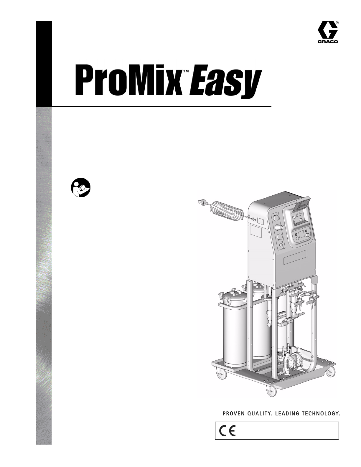
Plural Component Proportioner, with carbon steel UltraMix™ Pump,
cart, and remote mix manifold
250 psi (1.7 MPa, 17 bar) Maximum Fluid Working Pressure
Important Safety Instructions
Read all warnings and instructions in this manual.
Save these instructions.
See page 3 for model information, including
maximum working pressure and approvals.
Model 249320 Clear Coat System Shown
Graco Inc. P.O. Box 1441 Minneapolis, MN 55440-1441
Copyright 2005, Graco Inc. is registered to I.S. EN ISO 9001
TI6384a
Page 2
Contents
Manual Conventions
Manual Conventions . . . . . . . . . . . . . . . . . . . . . . . . 2
ProMix Easy Models . . . . . . . . . . . . . . . . . . . . . . . . 3
Related Manuals . . . . . . . . . . . . . . . . . . . . . . . . . . . 3
Warnings . . . . . . . . . . . . . . . . . . . . . . . . . . . . . . . . . 4
WARNING . . . . . . . . . . . . . . . . . . . . . . . . . . . . . . . . . 4
Overview . . . . . . . . . . . . . . . . . . . . . . . . . . . . . . . . . . 6
Installation . . . . . . . . . . . . . . . . . . . . . . . . . . . . . . . 11
Setup . . . . . . . . . . . . . . . . . . . . . . . . . . . . . . . . . . . . 12
Pressure Relief Procedure . . . . . . . . . . . . . . . . . . 14
Flushing . . . . . . . . . . . . . . . . . . . . . . . . . . . . . . . . . 16
Priming . . . . . . . . . . . . . . . . . . . . . . . . . . . . . . . . . . 19
Pump Test . . . . . . . . . . . . . . . . . . . . . . . . . . . . . . . 20
Manual Conventions
WARNING
Hazard Symbol
WARNING: a potentially hazardous situation which, if
not avoided, could result in death or serious injury.
Warnings in the instructions usually include a symbol
indicating the hazard. Read the general Warnings
section for additional safety information.
Spraying . . . . . . . . . . . . . . . . . . . . . . . . . . . . . . . . . 21
Batch Dispense or Ratio Check . . . . . . . . . . . . . . 22
Pot Life Timer . . . . . . . . . . . . . . . . . . . . . . . . . . . . . 23
Recirculation Setting . . . . . . . . . . . . . . . . . . . . . . . 24
Shutdown . . . . . . . . . . . . . . . . . . . . . . . . . . . . . . . . 25
Recalibrate System . . . . . . . . . . . . . . . . . . . . . . . . 26
Alarms . . . . . . . . . . . . . . . . . . . . . . . . . . . . . . . . . . . 28
Performance Charts . . . . . . . . . . . . . . . . . . . . . . . . 30
Technical Data . . . . . . . . . . . . . . . . . . . . . . . . . . . . 31
Graco Standard Warranty . . . . . . . . . . . . . . . . . . . 32
Graco Information . . . . . . . . . . . . . . . . . . . . . . . . . 32
CAUTION
CAUTION: a potentially hazardous situation which, if
not avoided, may result in property damage or
destruction of equipment.
Note
Additional helpful information.
2 311003B
Page 3
ProMix Easy Models
Approved for Hazardous Location
Class I, Div 1, Group D (North America); Class I, Zones 1 and 2 (Europe)
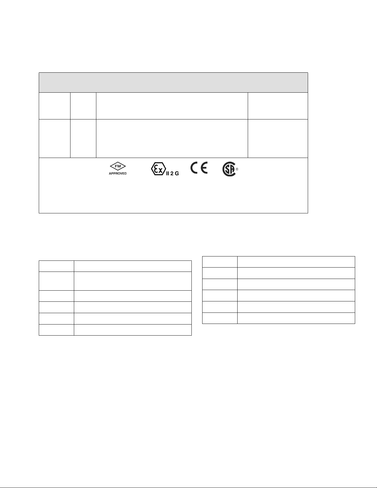
ProMix Easy Models
ProMix
Easy
Part No. Series Description and Approvals
249320
A
Clear coat system; cart mount, UltraMix carbon steel
pumps, and remote mix manifold
249321
A
Primer system; cart mount, UltraMix carbon steel
pumps, and remote mix manifold
Conforms to
FM std 3600 & 3610
for use in
Class I Div 1
Group D T3
Hazardous Locations
ISSeP 04 ATEX 020X
EEx ib IIA T3
Related Manuals
Manual Description
311004 ProMix Easy with Remote Mix Manifold,
Repair-Parts Manual
Maximum
Working Pressure
psi (MPa, bar)
250 (1.7, 17)
250 (1.7, 17)
CAN/CSA
22.2 No. 157-92
& No. 1010.1-92
Manual Description
310675 AC Power Supply
310678 TSL Pump Kits
310655 Dispense Valve
310662 Displacement Pumps
310671 UltraMix Pumps
310700 Gun Air Regulator Kits
309623 Data Download Kits
308034 Turbine Alternator Repair Kit
310673 Circulation Kits
311003B 3
Page 4
Warnings
Warnings
The following general warnings are related to the safe setup, use, grounding, maintenance and repair of this equipment. Additional more specific warnings may be found throughout the text of this manual where applicable.
WARNING
FIRE AND EXPLOSION HAZARD
Flammable fumes, such as solvent and paint fumes, in work area can ignite or explode. To help prevent
fire and explosion:
• Use equipment only in well ventilated area.
• Eliminate all ignition sources; such as pilot lights, cigarettes, portable electric lamps, and plastic drop
cloths (potential static arc).
• Keep work area free of debris, including solvent, rags and gasoline.
• Do not plug or unplug power cords, or turn power or light switches on or off when flammable fumes
are present.
• Ground all equipment in work area. See Grounding instructions.
• Use only grounded hoses.
• Hold gun firmly to side of grounded pail when triggering into pail.
• If there is static sparking or you feel a shock, stop operation immediately. Do not use equipment
until you identify and correct the problem.
• Keep a fire extinguisher in the work area.
PRESSURIZED EQUIPMENT HAZARD
Fluid from the gun/dispense valve, leaks, or ruptured components can splash in the eyes or on skin and
cause serious injury.
• Follow Pressure Relief Procedure in this manual, when you stop spraying and before cleaning,
checking, or servicing equipment.
• Tighten all fluid connections before operating the equipment.
• Check hoses, tubes, and couplings daily. Replace worn or damaged parts immediately.
EQUIPMENT MISUSE HAZARD
Misuse can cause death or serious injury.
• Do not exceed the maximum working pressure or temperature rating of the lowest rated system
component. See Technical Data in all equipment manuals.
• Use fluids and solvents that are compatible with equipment wetted parts. See Technical Data in all
equipment manuals. Read fluid and solvent manufacturer’s warnings.
• Check equipment daily. Repair or replace worn or damaged parts immediately.
• Do not alter or modify equipment.
• For professional use only.
• Use equipment only for its intended purpose. Call your Graco distributor for information.
• Route hoses and cables away from traffic areas, sharp edges, moving parts, and hot surfaces.
• Do not kink or overbend hoses or use hoses to pull equipment.
• Comply with all applicable safety regulations.
4 311003B
Page 5
Warnings
WARNING
MOVING PARTS HAZARD
Moving parts can pinch or amputate fingers and other body parts.
• Keep clear of moving parts.
• Do not operate equipment with protective guards or covers removed.
• Pressurized equipment can start without warning. Before checking, moving, or servicing equipment,
follow the Pressure Relief Procedure in this manual. Disconnect power or air supply.
TOXIC FLUID OR FUMES HAZARD
Toxic fluids or fumes can cause serious injury or death if splashed in the eyes or on skin, inhaled, or
swallowed.
• Read MSDS’s to know the specific hazards of the fluids you are using.
• Store hazardous fluid in approved containers, and dispose of it according to applicable guidelines.
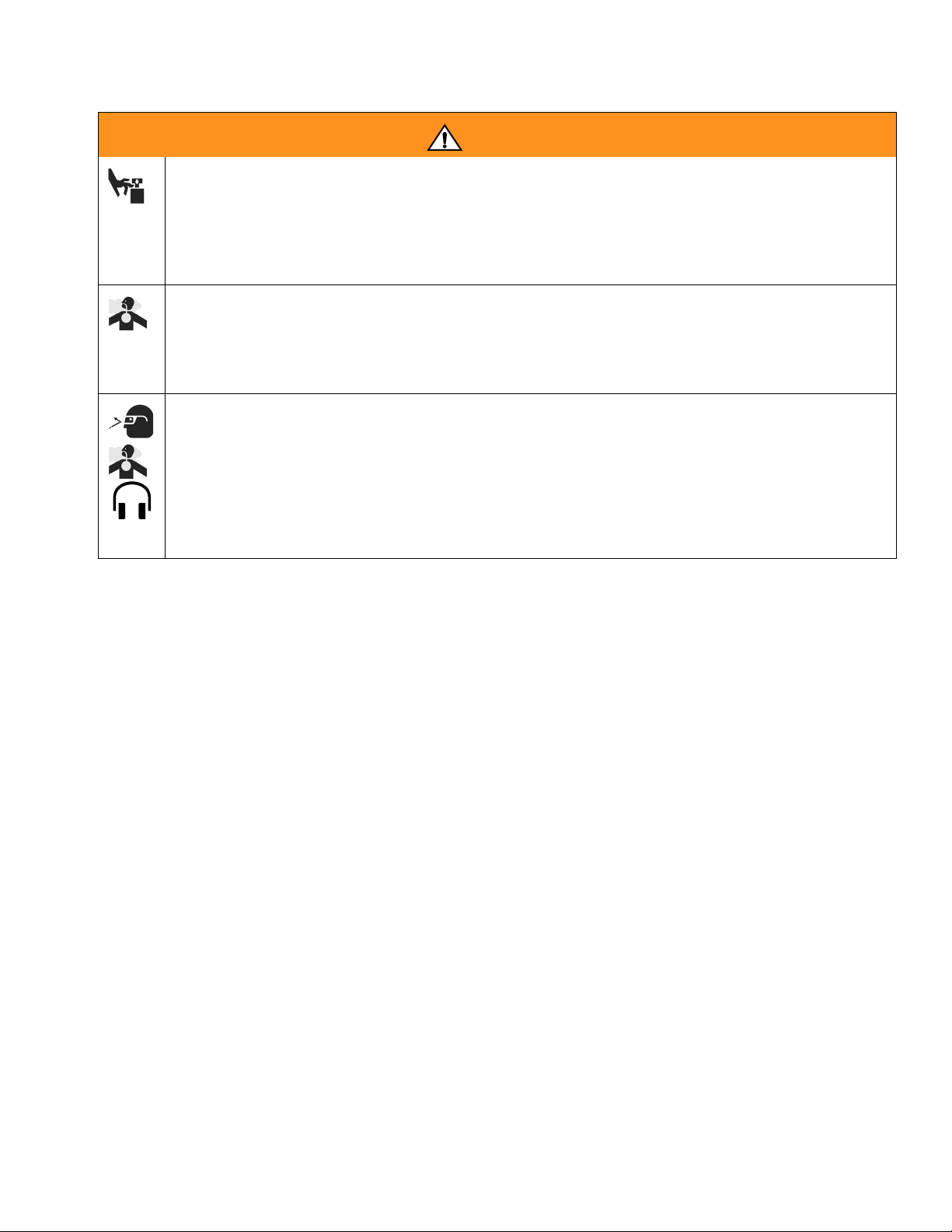
PERSONAL PROTECTIVE EQUIPMENT
You must wear appropriate protective equipment when operating, servicing, or when in the operating
area of the equipment to help protect you from serious injury, including eye injury, inhalation of toxic
fumes, burns, and hearing loss. This equipment includes but is not limited to:
• Protective eyewear
• Clothing and respirator as recommended by the fluid and solvent manufacturer
•Gloves
• Hearing protection
311003B 5
Page 6
Overview
Usage
The ProMix Easy can mix most two-component paints. It
is not for use with “quick-setting” paints (those with a pot
life of less than 5 minutes) without modification. Contact
your distributor for information.
The ProMix Easy is operated with the User Interface, Air
Controls and Fluid Controls, described below and on
page 7. Refer to F
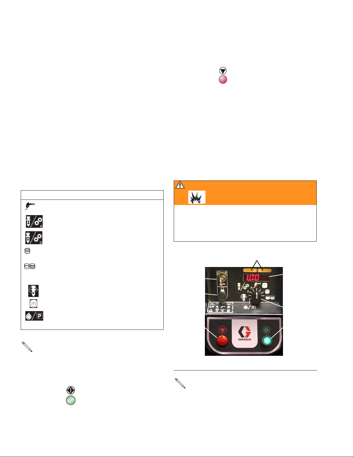
User Interface
The User Interface has 6 main interfaces.
1. Function Knob to select desired function:
Icon Function
IG. 1 and FIG. 3.
Spray: proportion and spray material.
Run A: operate A independent of B (prim-
ing, flushing) for 12 cycles.
Run B: operate B independent of A (priming, flushing) for 12 cycles.
Batch Dispense: dispense proportioned
amounts of A and B (1 pint/500 cc).
Pump Test: dispense predetermined
amount of A and B to verify pump operation.
Recirculation: optional; requires 248652
Circulation Kit, see page 24.
Pot Life Timer: display potlife time left.
Pressure Relief/Park: allows pressure relief
and runs pumps to the bottom of stroke.
See page 14.
Overview
3. Stop button to terminate functions.
4. Key switch to change ratio, pot life time, pot life vol-
ume, or calibration data.
5. Display (five digits) to view:
• Software revision level at startup
•Ratio
• Pot life time and reset volume
• Alarm codes
• Sensor calibration factor.
6. Data port allows for connection to a PC serial port
to download volume totalizer, operation, ratio setting, and error alarm data.
WAR NING
To avoid impairing intrinsic safety and reduce the risk
of fire and explosion, the PC must be in a non-hazardous location and a safety barrier must be installed
between the PC and ProMix Easy unit. See data
download kit manual 309623.
LT
4
5
6
1
3
2
• System totalizers count in Spray and Batch
Dispense functions only.
F
• A and B Indicators (LT) show which dispense
valve(s) is open.
2. Start button to initiate functions.
6 311003B
IG. 1. User Interface
You must recalibrate the circuit board whenever the
main circuit board, software, or sensor is replaced,
or when Alarm 8 occurs. See Recalibrate System,
page 26.
Page 7
Overview
Air Controls
See FIG. 3.
• Bleed-type main air shutoff valve (C), shuts off all
air to ProMix Easy (including controller power).
• Supply air pressure gauge (D), monitors air pressure to ProMix Easy.
A minimum air pressure supply of 70 psi (483 kPa,
4.8 bar) must be maintained for the ProMix Easy
to operate properly.
• Pump air pressure regulator (E) with gauge (F),
adjusts and monitors pump air pressure.
• Gun air regulator (P) and gauge (shipped loose),
adjusts and monitors gun air pressure.
Solenoid Module
There are two solenoids inside the pneumatic control
box, one to actuate dispense valve A, one to actuate
dispense valve B.
Fluid Supply Containers
Clear coat systems include three feed pots (H, J, L) for
components A
1, A2, and B.
Primer systems include two feed pots (H, L) for components A and B.
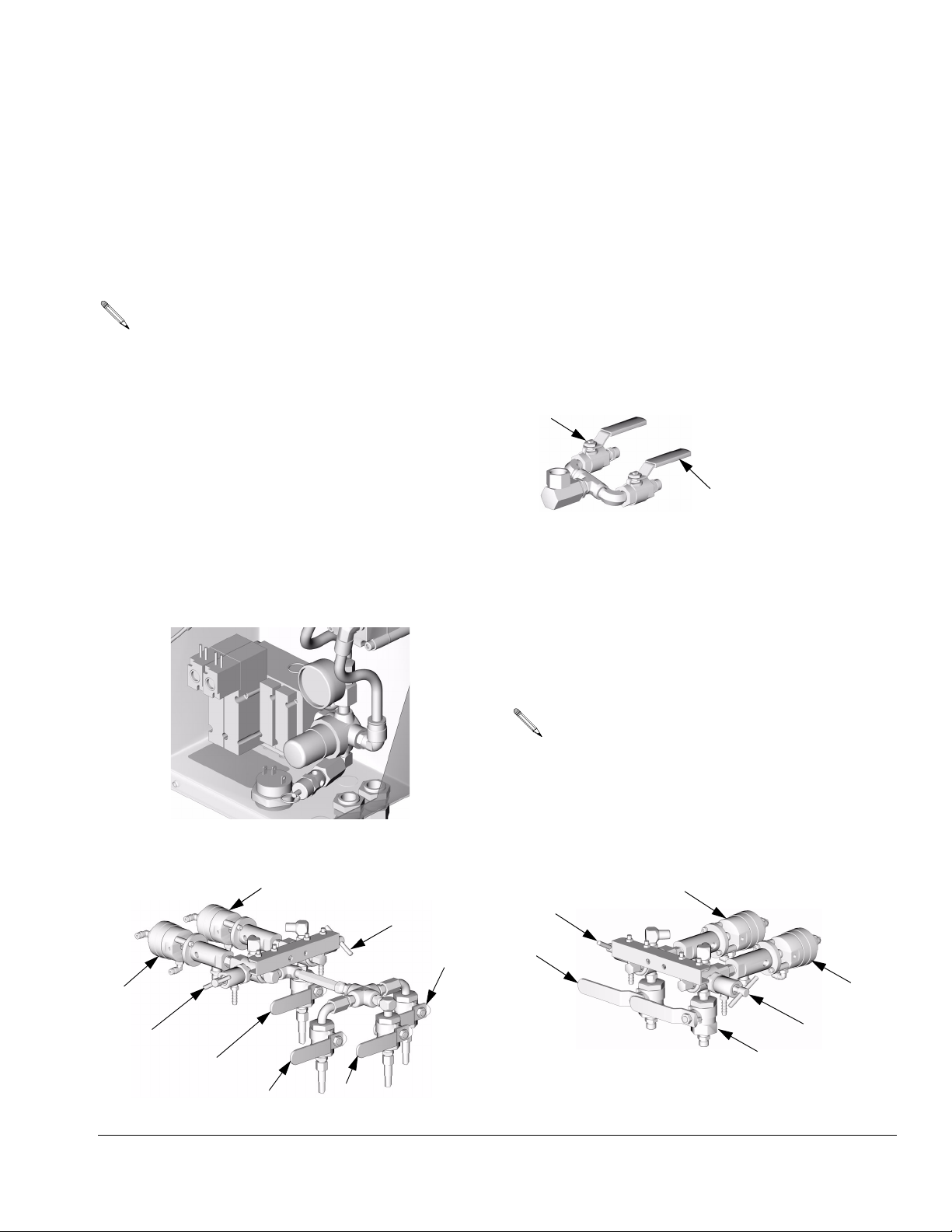
Fluid Control Valves
• Fluid inlet valve manifold (M, clear coat systems
only) allows component A
and/or A
2 FAST CLEAR (blue) to enter component A
pump.
A1
• Dispense valves (DA, DB) dispense the correct
dose of component A and component B to the
remote mix manifold. Solenoids A and B turn the
dispense valves ON and OFF. See F
• Sampling valves (SA, SB), to batch dispense or
test pumps. See F
IG. 2.
1 SLOW CLEAR (green)
A2
IG. 2.
TI6356a
• Fluid outlet valves allow components A and B to
enter the fluid hoses. See F
AB
Clear coat systems use a fluid outlet valve manifold
(N) on the A side: A
CLEAR
TI4808a
Clear Coat System Primer System
DB
SB
2
A
DA
SA
B
A1 A1 + A2
TI6428a
FIG. 2. Dispense Valves, Sampling Valves, and Fluid Outlet Valves
SA
A
IG. 2.
1 SLOW CLEAR (green), A2 FAST
(blue), or A1+A2 MEDIUM CLEAR (green/blue).
DA
DB
SB
B
TI6510a
311003B 7
Page 8
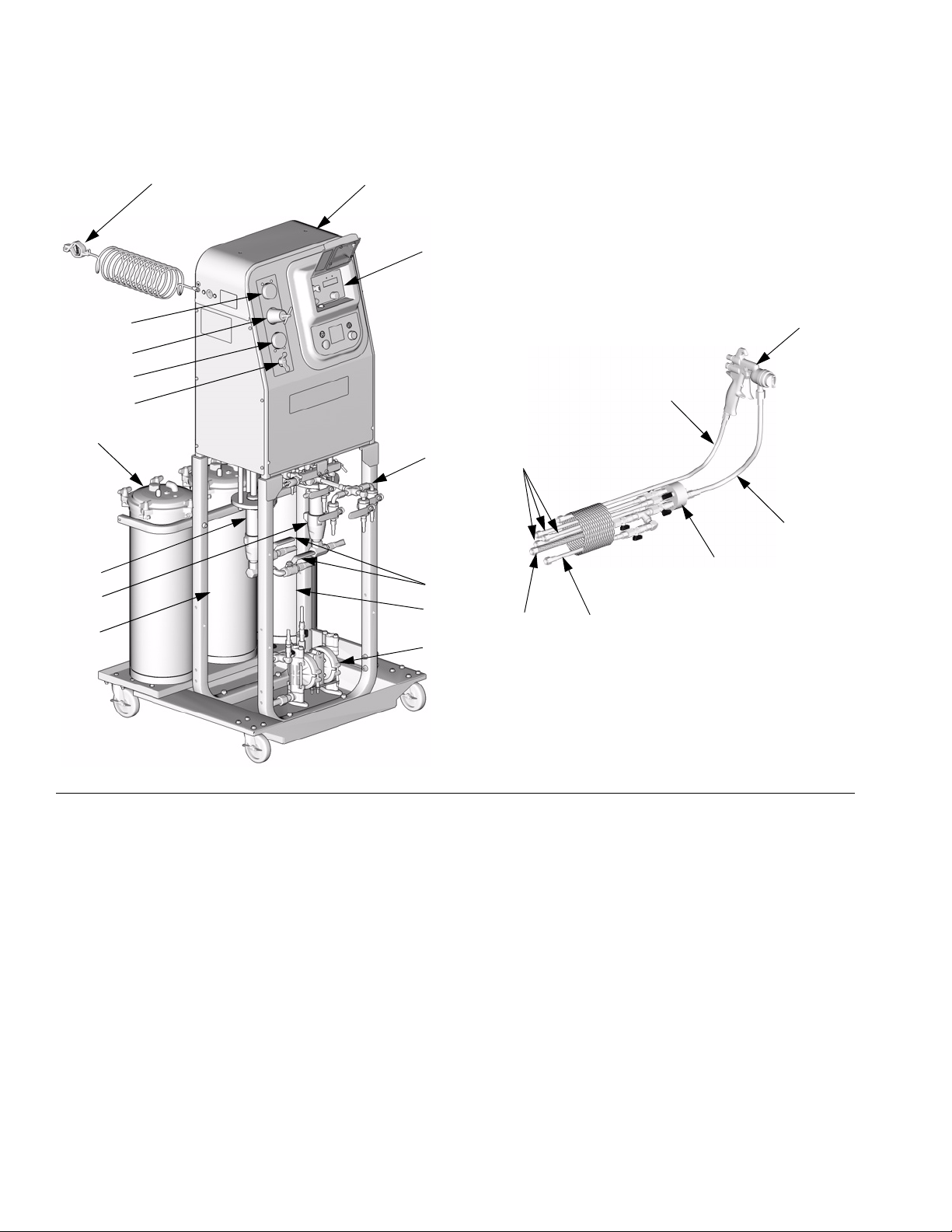
Overview
Y
F
V
Z
X
E
D
R
C
H
N
A
W
G
K
J
M
L
B
S
T
TI6607a
U
TI6384a
FIG. 3. ProMix Easy Proportioner, Major Components (Clear Coat System Shown)
Key for F
A Component A Fluid Hoses
B Component B Fluid Hose (braided)
C Bleed-Type Main Air Shutoff Valve
D Air Supply Pressure Gauge
E Pump Air Regulator
F Pump Air Pressure Gauge
G Component A Pump
H Component A
J Component A2 Feed Tank (clear coat systems only)
K Component B Pump
L Component B Feed Tank
8 311003B
IG. 3
1 Feed Tank
M Fluid Inlet Valves (clear coat systems only)
N Fluid Outlet Valve Manifold (clear coat systems only)
P Gun Air Pressure Regulator (not shown)
R Gun Air Supply Hose
S Solvent Supply Hose
T Remote Mix Manifold
U Solvent Pump
V ProMix Easy Plural Component Proportioner
W Fluid Whip Hose/Static Mixer
X Air Spray Gun (not included with system)
Y Ground Wire
Z User Interface (see page 6)
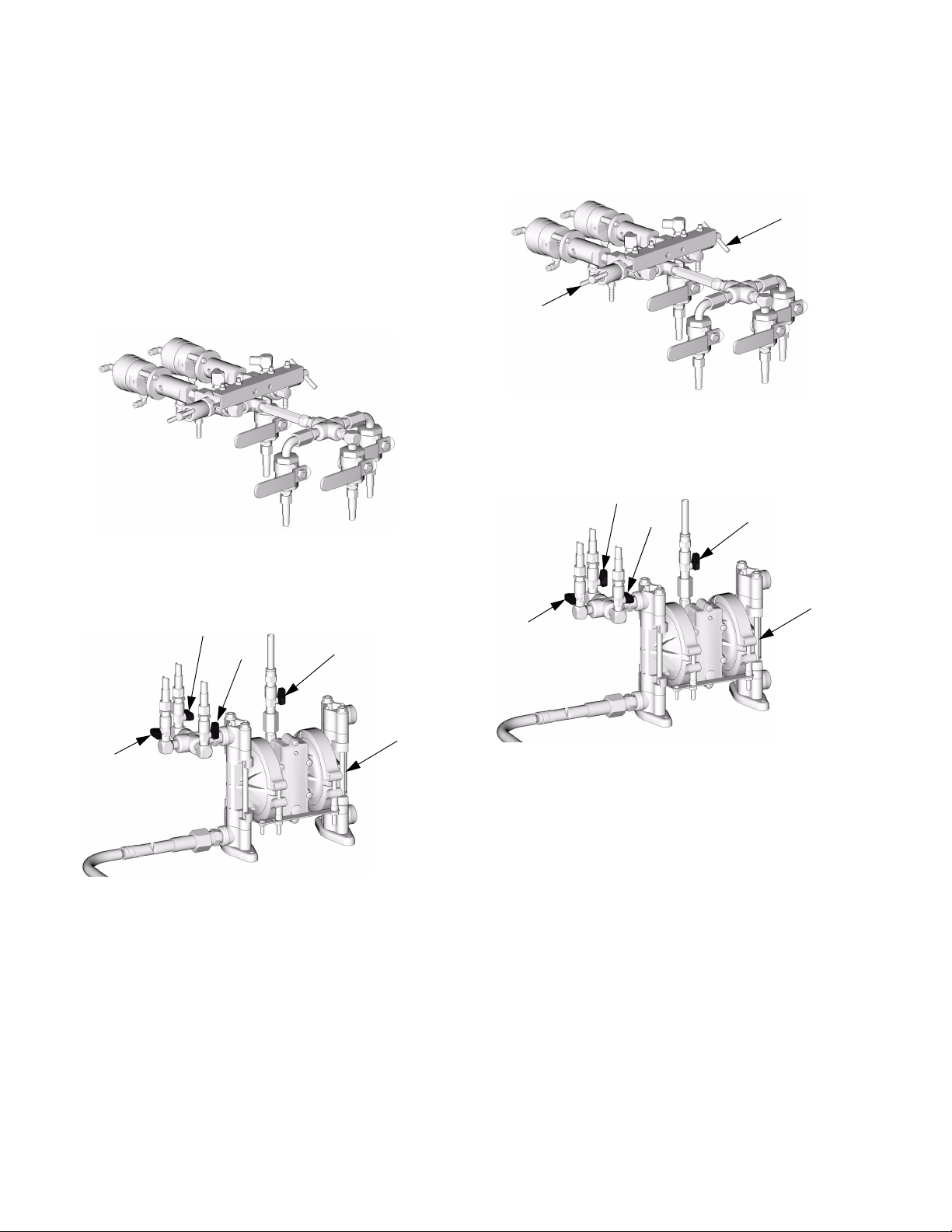
Page 9
Solvent Control Valves
Solvent pump (U) pumps solvent from a user-supplied
solvent container.
• Solvent pump air valve (SV) turns on the solvent
pump.
• A and B solvent valves (VA, VB) allow flushing of
sampling valves A and B.
• Solvent valves allow flushing of the mix manifold,
whip hose, and gun. Valve S1 is at the solvent pump
outlet. Valve S2 is at the mix manifold.
Overview
VB
SVVA
U
S1
TI6425a
On clear coat systems, valves S1, S2, and B2 must
all be open to flush the mix manifold. See F
IG. 5.
F
IG. 4. Solvent Pump and Valves
311003B 9
Page 10
Overview
Hose Bundle/Mix Manifold
The hose bundle includes fluid hoses, solvent hose, air
hose, mix manifold, and whip hose/static mixer. Hoses
are encased in a protective cover.
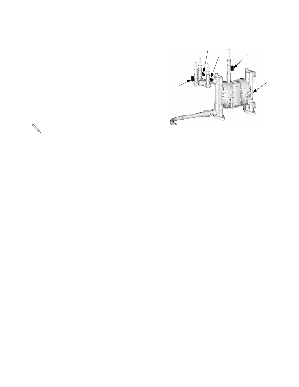
Clear Coat Systems
See FIG. 5. Clear coat system hose bundle includes a
gun air supply hose (R), solvent hose (S), and four fluid
hoses. The component B hose is steel braid. The three
nylon fluid hoses are for components A
The component A and component B hoses have fluid
shutoff valves upstream of the mix manifold. These
valves are all open when spraying. Close these valves at
Shutdown, page 25.
Solvent valve (S2) is always closed except when flushing (see Mix Manifold Flushing, page 16). (Valve B2
must also be open when flushing to allow solvent into
the mix manifold.) Check valves (CB) are provided to
prevent cross-contamination of the solvent line and fluid
lines.
1, A2, and A1+A2.
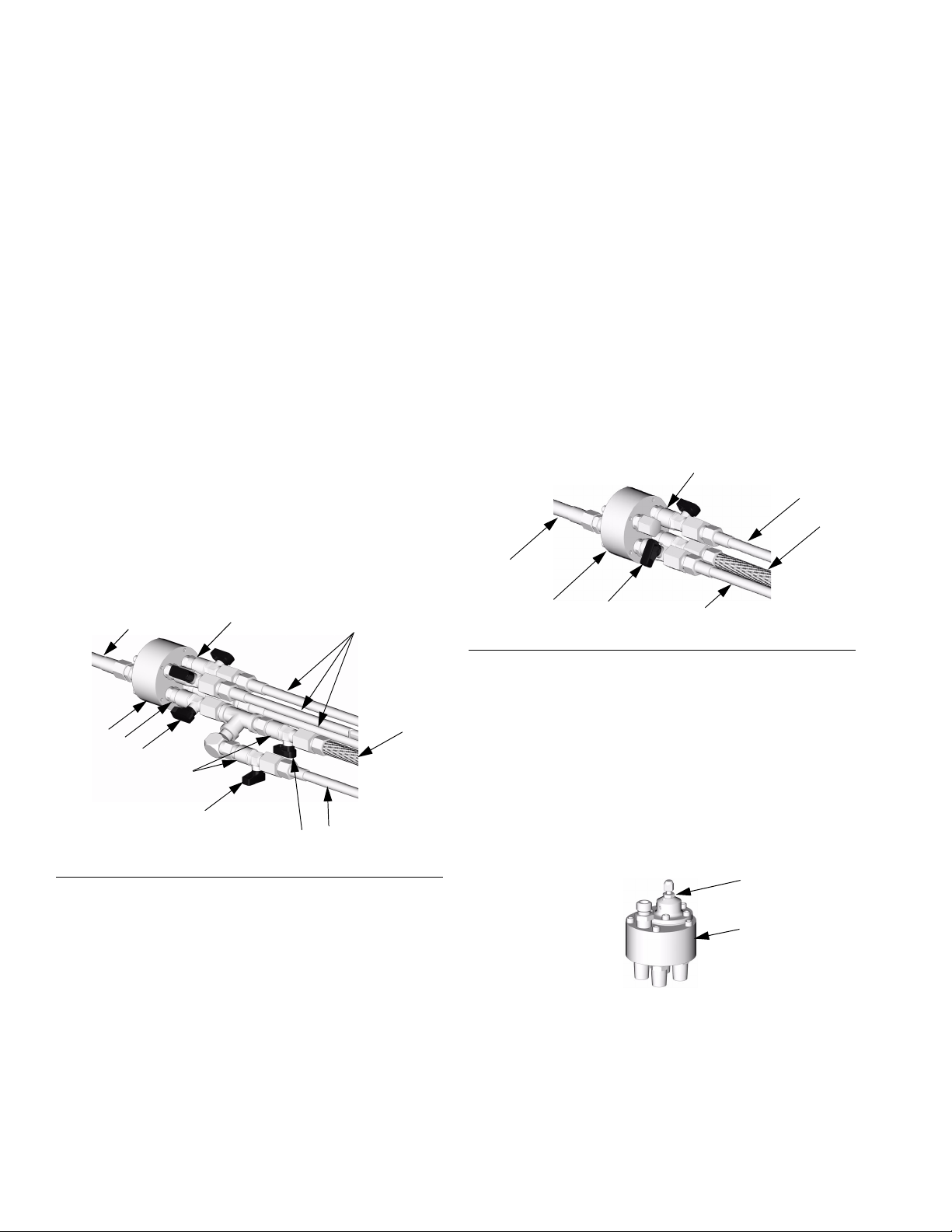
Primer Systems
See FIG. 6. Primer system hose bundle includes a gun
air supply hose (R), solvent hose (S), and component A
and B hoses. The component B hose is steel braid. The
component A hose is nylon.
The component A and component B hoses have fluid
shutoff valves upstream of the mix manifold. These
valves are both open when spraying. Close these valves
at Shutdown, page 25.
Solvent valve (S2) is always closed except when flushing (see Mix Manifold Flushing, page 16). Check
valves (CB) are provided to prevent cross-contamination
of the solvent line and fluid lines.
CB
A
B
W
W
T
CB
CB
A
B2
CB
S2
B1
S
F
IG. 5. Mix Manifold Valves, Clear Coat Systems
B
TI6424a
T
IG. 6. Mix Manifold Valves, Primer Systems
F
S2
S
TI6603a
Remote Mix Manifold
• Components A and B are pre-mixed in the mix manifold (T), then uniformly blended in the whip
hose/static mixer (W) before being sprayed.
• Use the built-in fluid regulator (FR) to adjust fluid
pressure to the spray gun. Regulator must be open
to permit flow.
FR
T
TI6606a
10 311003B
Page 11

Installation
Installation
The Typical Installation shown in FIG. 3 is not an actual
system design. Contact your Graco distributor for assistance in designing your system. Be sure all accessories
are adequately sized and pressure-rated to meet system requirements.
Reference numbers and letters in the text refer to numbers and letters in the figures.
Icons in the text refer to icons on the User Interface.
WAR NING
Read warnings, page 4. Ground equipment as
instructed below.
1. Connect ProMix Easy ground wire (Y) to a true earth
ground.
Y
4. Connect the component A and component B fluid
lines of hose bundle (S) to the fluid outlet valves,
according to labels on the hoses.
5. Connect the solvent hose (S) to solvent valve S1 at
the solvent pump (U). (Two hoses to flush sampling
valves are pre-attached at the factory.)
6. Install the gun air regulator (P) in a convenient, eas-
ily accessible location for the operator. See manual
310700.
7. Connect the air hose (R) between the outlet of the
gun air regulator and the air inlet of the spray gun
(X).
X
R
TI4792a
2. Locate the ProMix Easy in a convenient location.
Ensure there is adequate clearance on all sides for
operator access and servicing.
3. Clear coat systems only: install the fluid outlet valve
manifold. See F
IG. 2.
TI4837a
8. Connect the fluid whip hose/static mixer (W) to the
fluid inlet of the spray gun (X).
X
W
TI4854a
311003B 11
Page 12

Setup
Setup
1. Tighten all hose connections and all fittings on unit.
2. Fill pumps A and B packing nuts with throat seal liq-
uid (TSL).
3. Connect main air supply line (AL) to air inlet.
Air supply requirement: 110 psi (0.8 MPa, 8 bar)
maximum, 70 psi (483 kPa, 4.8 bar) minimum; 20
3
scfm (0.56 m
/min).
5. Open main air shutoff valve. When starting up, dis-
play will show “88888”, then software revision, then
current ratio (if set to or
).
6. Setup ratio.
a. Turn function knob to .
b. Current ratio displays.
c. To change ratio, turn key to + or – until desired
ratio is displayed, then turn key back to neutral.
AL
4. Set air regulator to 0.
7. Flush and prime system. See pages 16 and 19. Run
Pump Test, page 20 to check ratio accuracy.
12 311003B
Page 13

Setup
Setting Valves on a Clear Coat
System
Clear coat systems include three component A fluid
lines. Set the fluid inlet and outlet valves as follows.
Component A1 SLOW CLEAR Dispense
1. Open A1 fluid inlet and outlet valves (green). Close
A1
IG. 7.
TI6419a
all other fluid inlet and outlet valves. See F
IG. 7. Component A1 Dispense
F
2. At remote mix manifold, close solvent valve S2.
Open all other valves. See F
IG. 5.
Component A1+A2 MEDIUM CLEAR Dispense
To dispense equal parts of components A1 and A2:
1. Open A1 (green) and A2 (blue) fluid inlet valves.
Open A
other fluid outlet valves. See F
F
IG. 9. Component A1+A2 Dispense
1+A2 fluid outlet valve (green/blue). Close all
IG. 9.
A1
A2
A1 + A2
TI6421a
2. At remote mix manifold, close solvent valve S2.
Open all other valves. See F
IG. 5.
Component A2 FAST CLEAR Dispense
1. Open A2 fluid inlet and outlet valves (blue). Close all
A2
IG. 8.
TI6420a
other fluid inlet and outlet valves. See F
F
IG. 8. Component A2 Dispense
2. At remote mix manifold, close solvent valve S2.
Open all other valves. See F
IG. 5.
Component B Dispense
1. Open component B fluid outlet valve.
B
TI6422a
2. See FIG. 5. At remote mix manifold, open valves
and B2. B1 is upstream of the check valve (CB), and
B2 is close to the mix manifold.
B1
311003B 13
Page 14

Pressure Relief Procedure
Pressure Relief
Procedure
WARNING
Relieve pressure from mix manifold to gun whenever
you stop spraying and before servicing gun or removing nozzle.
In addition, relieve pressure from pump to gun at end
of day and before cleaning, checking, or servicing
pump, manifold, or fluid line accessories or transporting equipment. See page 15.
Read warnings, page 4.
Mix Manifold to Gun
1. Press .
2. Close all valves at mix manifold.
3. Hold a metal part of the gun firmly to a grounded
metal pail. Trigger gun to relieve pressure.
TI4836a
14 311003B
Page 15

Pressure Relief Procedure
Pump to Gun
1. Open all fluid valves at mix manifold. Leave solvent
valve (S2) closed.
TI6424a
S2
2. Open all fluid outlet valves.
3. Turn function knob to pressure relief/park .
Pump air supply pressure must be sufficient to
cause pumps to stroke to bottom-most position
when function knob to is set to pressure relief/park
.
5. Hold a metal part of the gun firmly to a grounded
metal pail. Trigger gun to relieve component A pressure. Indicator A will stay on for 5 sec after Pump A
reaches Park position, then go off.
TI4836a
6. Indicator B comes on and Pump B pressurizes.
7. Hold a metal part of the gun firmly to a grounded
metal pail. Trigger gun to relieve component B pressure. Indicator B will stay on for 5 sec after Pump B
reaches Park position, then go off.
4. Press . Indicator A comes on, and Pump A pres-
surizes.
If both pumps are not parked after 1 min, Alarm
26 will sound.
311003B 15
TI4836a
Page 16

Flushing
Flushing
• There are times when you only want to flush the mix
manifold, such as:
• breaks in spraying
• overnight shutdown
• end of potlife
In this manual, this procedure is referred to as Mix
Manifold Flushing (see this page).
• Other times, Full System Flushing (page 17) is
necessary:
• first time material is loaded into equipment*
• material change
•servicing
• putting equipment into storage
* Some Full System Flushing steps are not neces-
sary for initial flushing, as no material has been
loaded into the system yet.
• After doing a pump test or ratio check, you need to
Flush Sampling Valves (page 18).
2. Open valves S2 and B2 at mix manifold. Close all
other mix manifold valves.
B2
S2
TI6423a
3. Ensure that valves VA and VB at solvent pump are
closed. Open valve S1. Open valve SV to turn on
solvent pump.
VB
SVVA
WAR NING
Read warnings, page 4.
• Use the lowest possible pressure when flushing to avoid splashing.
• Before material change or shutdown for storage, flush at a higher flow rate and for a longer
time.
Mix Manifold Flushing
1. Follow complete Pressure Relief Procedure, pages
14 and 15. Ensure that A and B pumps are parked
before proceeding.
CAUTION
Do not exceed 100 psi (0.7 MPa, 7 bar) air input pressure to the solvent pump.
U
S1
TI6425a
4. Trigger gun into a grounded pail. Flush through gun
until clean solvent flows.
TI4836a
5. Close valve SV to shut off solvent pump.
6. Trigger gun to relieve solvent pressure.
7. Close solvent valve(s) S1, S2.
16 311003B
Page 17

Flushing
Full System Flushing
Use the lowest possible pressure while flushing, to
avoid splashing.
1. Follow Pressure Relief Procedure, page 14. Set air
regulator to 0, and close main air shutoff valve.
2. Replace component A and B supplies with solvent.
3. Set air regulator to 50 psi (345 kPa, 3.4 bar).
4. Turn function knob to A . Press .
6. Ensure that all valves at mix manifold are open.
TI6385a
7. Open sampling valve SA slowly. Pump A will run for
12 cycles, then stop. Restart as needed. When
clean solvent flows from sampling valve SA, close
valve.
5. Open fluid outlet valve A.
A
On clear coat systems, flush each component A
hose independently, to ensure sufficient pressure
to clean the lines thoroughly. See Setting Valves
on a Clear Coat System, page 13.
TI6604a
SA
TI6428a
8. Trigger gun into grounded pail until clear solvent
flows from gun. You may have to press more
than once. When solvent is clear, press .
9. Repeat steps 4-8 for the B side.
10.Follow Pressure Relief Procedure, page 14, and
remove gun from hose. See gun manual to further
clean gun.
Some materials require additional cleaning. You
may need to circulate solvent through the system.
311003B 17
Page 18
Flushing
Flush Sampling Valves
Flush the sampling valves after doing a pump test (page
20) or ratio check (page 22).
1. Follow Pressure Relief Procedure, page 14.
2. Close all fluid outlet valves.
TI6428a
3. Open valve VA and close valves S1 and VB at sol-
vent pump. Turn on solvent pump.
VB
SVVA
4. Open sampling valve SA. When clean solvent flows
from sampling valve SA, close valve.
SB
SA
TI6428a
5. Close valve VA and open valve VB at solvent pump.
Repeat for component B side.
VB
SVVA
U
S1
S1
U
TI6427a
TI6426
18 311003B
Page 19

Priming
Priming
Use the lowest possible pressure while priming, to
avoid splashing.
1. Connect fluid supply hoses to A and B pumps.
Tighten all hose connections and fittings.
2. Set air regulator to 0.
4. Open all fluid valves at mix manifold. Leave solvent
valve (S2) closed. Ensure that fluid regulator (FR) is
open, to permit flow.
TI6424a
S2
5. Turn function knob to A . Press . Turn up
air regulator slowly until pump A starts. Trigger gun
into grounded pail until fluid flows steadily from gun.
You may have to press more than once. When
3. Open fluid outlet valve A.
A
On clear coat systems, prime each component A
hose independently. See Setting Valves on a
Clear Coat System, page 13.
TI6604a
1 hose and gun are primed, press .
A
When run independently (set to A or B), the pump
runs for 12 cycles, then stops. Press and
as needed to prime.
6. Repeat steps 3-5 for the B side.
7. Test spray a pattern to ensure you get desired
results. Perform Pump Test, page 20.
311003B 19
Page 20

Pump Test
Pump Test
Follow this procedure the first time system is operated
(after flushing and priming).
The volume dispensed during the pump test (5 cycles) is
270 cc. Dispense into a container with adequate graduations.
1. Turn function knob to . Set air regulator to 0.
Open main air shutoff valve. Adjust air pressure to
50 psi (0.35 MPa, 3.5 bar).
e. Slowly open and adjust sampling valve SA to
achieve desired flow. The pump stops automatically after 5 cycles. During the last cycle the
pump will stop once on the upstroke and once
on the downstroke to perform a pump stall test.
Indicator A turns off, indicator B comes on.
SA
TI6428a
3. Close sampling valve SA.
4. Dispense fluid B as follows:
a. Place a clean 1 quart (1000 cc) container under
sampling valve SB.
2. Dispense fluid A:
a. Close all fluid outlet valves.
b. Close sampling valves (SA and SB).
c. Place a clean 1 quart (1000 cc) container under
sampling valve SA.
d. Press . Indicator A comes on.
b. Slowly open and adjust sampling valve SB to
achieve desired flow. The pump stops automatically after 5 cycles. Indicator B turns off.
SB
TI6428a
5. Close sampling valve SB.
6. Compare fluid amounts in the containers; they
should be about equal. Repeat test if fluids are not
equal. If problem persists, contact Graco engineering.
If pump fails any of pump stall tests, alarm will display (see alarms 15-20, page 29).
7. Flush Sampling Valves, page 18.
20 311003B
Page 21

Spraying
Spraying
1. Close sampling valves SA and SB.
2. Open fluid outlet valves.
On clear coat systems, open appropriate fluid inlet
and outlet valves, depending on desired dispense
configuration. See Setting Valves on a Clear Coat
System, page 13.
3. At remote mix manifold, close valve S2. Ensure that
all other valves at mix manifold are open.
TI6424a
S2
5. Trigger gun into a pail and slowly increase air regula-
tor pressure until pump is running and consistently
mixed material is dispensed.
TI4836a
6. Press .
7. Adjust air regulator to the necessary spraying pres-
sure; see gun manual. You can also adjust fluid
pressure with the fluid regulator on the mix manifold.
Press to proportion and spray a test pattern.
See gun manual for spray pattern adjustments to get
desired results.
4. Turn function knob to . Press .
8. Follow Mix Manifold Flushing, page 16, or Shut-
down, page 25, when you are done spraying or
before potlife expires.
Mixed material potlife or working time
decreases with increased temperature.
311003B 21
Page 22

Batch Dispense or Ratio Check
Batch Dispense or Ratio Check
Batch dispense is always 1 pint (500 cc) of total
volume, regardless of ratio setting.
Follow this procedure to dispense a batch (into one container) or verify a ratio setting (use separate container
for fluid A and B). Dispense into a container with graduations no greater than 5% of each component.
1. Turn function knob to . Set air regulator to 0.
Open main air shutoff valve. Adjust air pressure to
50 psi (0.35 MPa, 3.5 bar).
e. Slowly open and adjust sampling valve SA to
achieve desired flow. The pump stops automatically when dispense is complete. Indicator A
turns off, indicator B comes on.
SA
TI6428a
3. Close sampling valve SA.
4. Dispense fluid B:
a. Batch dispense: move the 1 quart (1000 cc)
container under sampling valve SB.
Ratio check: place clean 1 quart (1000 cc) container under sampling valve SB.
2. Dispense fluid A:
a. Close all fluid outlet valves.
b. Close sampling valves (SA and SB).
c. Place a clean 1 quart (1000 cc) container under
sampling valve SA.
d. Press . Indicator A comes on.
On higher ratio settings, use a smaller container for
more accurate readings.
b. Slowly open and adjust sampling valve SB to
achieve desired flow. The pump stops automatically when dispense is complete. Indicator B
turns off.
SB
TI6428a
5. Batch dispense: stir material until mixed.
Ratio check: compare A and B fluid dispense.
6. Flush Sampling Valves, page 18.
7. To resume Spraying, see page 21.
22 311003B
Page 23

Pot Life Timer
Pot Life Timer
To Display Pot Life Time Left (in minutes)
Turn the function knob to .
How Pot Life Timer Works
Pot life timer starts to countdown at the start of
Spray mode. Once the pot life timer is active, it will
continue to time down, regardless of which mode the
system is in.
When the timer reaches zero, the system closes all dispense valves and a pot life (code 21) alarm occurs
(audible alarm sounds). Refer to page 28.
To Change Pot Life Time
Approximate Pot Life Volume
Volume of mix manifold, whip hose, and gun = 100 cc.
Pot Life Reset Volume
The timer resets when the total spray volume exceeds
the pot life reset volume.
To change reset value, hold down . Turn the key to
increase/decrease pot life reset volume (cc).
When an Alarm Occurs
Press to clear alarm, then flush system (page 16),
or press and spray until fresh material is loaded
into system.
Hold down . Turn the key to increase/decrease pot
life time (minutes).
Recommend setting pot life time to 1/2 of material
pot life.
311003B 23
Page 24

Recirculation Setting
Recirculation Setting
Fluid can be circulated up to the dispense valves with
the addition of Graco’s Circulation Kit 248652. Consult
your distributor.
During recirculation only the pump runs; A and B
dispense valves do not operate. Material pumped
in recirculation mode is not counted by the totalizer.
To set the ProMix Easy to circulate:
1. Decrease the pump air pressure supply to the mini-
mum required to maintain the desired circulation volume.
2. Turn function knob to .
3. Press .
To terminate circulation, press .
To begin circulating again, press .
To begin spraying, turn function knob to , reset
system to desired ratio, and adjust pump to spray pressure.
CAUTION
Be sure recirculation valve does not leak material
back to fluid supply while spraying.
24 311003B
Page 25

Shutdown
Shutdown
1. Follow Pressure Relief Procedure, page 14. Set air
regulator to 0, and close main air shutoff valve.
2. See Flushing, page 16.
a. For overnight shutdown, follow Mix Manifold
Flushing, page 16.
b. For prolonged shutdown, follow Full System
Flushing, page 17.
3. Follow Pressure Relief Procedure, pages 14 and
15.
4. Close all valves at the mix manifold.
5. Before prolonged shutdown: cap fluid outlets to
keep solvent in the lines. Fill pump A and B packing
nuts and dispense valve A and B wet cups with
throat seal liquid (TSL).
311003B 25
Page 26

Recalibrate System
Recalibrate System
Follow steps 1-9 whenever the main circuit board, software, or sensor is replaced, or when Alarm 8 occurs
(refer to page 28). If sensor only needs recalibration, follow steps 7-9.
If data download is used, set date and time after
calibrating, using ProMix Easy software.
Set Pump Calibration Value
1. Note calibration value (CV) on pump sensor.
CV
2. Open main air valve to start unit. Allow time for sys-
tem to boot up and display ratio setting.
Calibrate Pump Sensor
7. Trigger gun into a pail or open sampling valve SA or
SB.
TI4836a
SB
SA
TI6428a
3. Turn function knob to A or B .
4. Hold down (continue to hold until calibration
value is set in step 6). After 5 seconds, the default
calibration value (between 85000 - 95000) displays.
5. Turn key to change default to calibration value noted
in step 1 (left to decrease, right to increase).
6. Release after entering calibration value.
8. Hold down (continue to hold until told to
release). The current calibration value displays.
9. Press . Release first, then release .
The pump will cycle to the board end of sensor first,
then to the opposite end, and stop.
26 311003B
Page 27

Recalibrate System
311003B 27
Page 28

Alarms
• An alarm condition will shutdown equipment.
• See ProMix Easy Repair manual for troubleshooting and repair.
Code Alarm Active Problem Cause
Startup Errors
01 Sensor Error A* Always No signal from pump A
sensor
02 Sensor Error B* Always No signal from pump B
sensor
03 Communication Error* Always Loss of communication
between main and display boards
Operating Errors
04 not used
05 not used
06 Pump Error A** Spray
07 Pump Error B**
08 Sensor Code Error Always Sensor values reverted to
09 not used
10 not used
11 Sensor Reading Low A* Spray
12 Sensor Reading Low B*
13 Sensor Reading High A* Spray
14 Sensor Reading High B*
21 Pot Life Error Spray
Te st
Batch
Te st
Batch
Te st
Batch
first, then
Always
Pump does not stall after
top change over
Pump cavitating excessively
default
Pump stroke travels
beyond sensor range at
top change over
Pump stroke travels
beyond sensor range at
bottom change over
Pot life timer timed out Not enough material sprayed after last reset
* Indicates error where audible alarm sounds once briefly.
** Indicates error where audible alarm sound pulses.
Loose cable, failed sensor or cable, failed magnet
assembly
Loose cable, failed sensor or cable, failed magnet
assembly
Loose cable, failed board
Intake valve leak
Air in lines caused by loose fitting or use of agitator
Empty fluid supply
Sensor value data corrupt; board needs replacement
and /or recalibration
Sensor or bracket loose
Sensor magnet dirty
Sensor or bracket loose
Sensor magnet dirty
Alarms
28 311003B
Page 29

Code Alarm Active Problem Cause
Operating Errors
(continued)
22 not used
23 not used
24 not used
25 not used
26 Park Timeout Park Pumps not at bottom of
stroke
Testing Error
15 Piston packing/ball A* Test Pump does not com-
16 Piston packing/ball B*
17 Inlet Ball A* Test Pump does not com-
18 Inlet Ball B*
19 Dispense Valve A* Test Pump does not com-
20 Dispense Valve B*
27 Pump Calibration
Timeout A
28 Pump Calibration
Timeout B
Run A Pump doesn’t run
Run B
pletely stall in up stroke
pletely stall in downstroke
pletely stall in both up
and down strokes
through calibration
Sampling valves closed, or gun not triggered
Piston packing or ball check failure
Intake valve ball check failure
Throat packing or dispense valve failure
Sampling valves closed
Alarms
311003B 29
Page 30

Performance Charts
2.5:1 Ratio UltraMix Pump
Tested with 10W oil
250
(1.75, 17.5)
Performance Charts
Fluid Outlet Pressure, psi (MPa, bar)
200
(1.4, 14.0)
150
(1.05, 10.5)
100
(0.7, 7.0)
50
(0.35, 3.5)
100 psi (0.7 MPa, 7 bar)
70 psi (0.48 MPa, 4.8 bar)
40 psi (0.28 MPa, 2.8 bar)
0
0
0.1 (0.38) 0.3 (1.14)0.2 (0.76) 0.4 (1.52) 0.5 (1.90)
Fluid Flow, gpm (lpm)
(curves are representative of all ratios)
30 311003B
Page 31

Technical Data
Mix ratio range . . . . . . . . . . . . . . . . . . . . . . . . . . . . . . . . . 0.1:1-10:1 (in 0.1 increments)
Ratio tolerance range . . . . . . . . . . . . . . . . . . . . . . . . . . . . up to +/- 5%
Flow rates
Minimum . . . . . . . . . . . . . . . . . . . . . . . . . . . . . . . 0.02 qt/min (0.02 lpm)*
Maximum . . . . . . . . . . . . . . . . . . . . . . . . . . . . . . . 1 gpm (3.8 lpm)
Pump size . . . . . . . . . . . . . . . . . . . . . . . . . . . . . . . . . . . . . 54 cc/cycle
Pump cycle length
(one cycle = one upstroke and one downstroke) . . . . . . . 6 in. (152 mm)/cycle
Fluid viscosity range . . . . . . . . . . . . . . . . . . . . . . . . . . . . . 50-2000 cps
Fluid filtration . . . . . . . . . . . . . . . . . . . . . . . . . . . . . . . . . . 40 mesh standard
Maximum fluid working pressure . . . . . . . . . . . . . . . . . . . 250 psi (1.7 MPa, 17 bar)
Air supply pressure range . . . . . . . . . . . . . . . . . . . . . . . . . 70-110 psi (483-800 kPa, 4.8-8 bar)
Maximum air consumption at 100 psi (0.7 MPa, 7 bar) . .
Air inlet size . . . . . . . . . . . . . . . . . . . . . . . . . . . . . . . . . . . 1/2 npt(f)
Ambient temperature range
Operating . . . . . . . . . . . . . . . . . . . . . . . . . . . . . . . 32-104° F (0-40° C)
Storage . . . . . . . . . . . . . . . . . . . . . . . . . . . . . . . . 30-160° F (–1-71° C)
Environmental Conditions Rating . . . . . . . . . . . . . . . . . . . Altitude up to 4000 meters
Sound pressure** . . . . . . . . . . . . . . . . . . . . . . . . . . . . . . . 70.3 dBA
Sound power** . . . . . . . . . . . . . . . . . . . . . . . . . . . . . . . . . 78.4 dBA
Wetted parts
Pumps . . . . . . . . . . . . . . . . . . . . . . . . . . . . . . . . . See 310662
Dispense Valves . . . . . . . . . . . . . . . . . . . . . . . . . See 310655
PC Communications . . . . . . . . . . . . . . . . . . . . . . . . . . . . . RS-232
20 scfm (0.56 m
Maximum relative humidity to 99% up to 40° C
Pollution degree (1)
3
/min)
Technical Data
* Minimum flow rate is dependent on the material being sprayed and mixing capability. Test your material for spe-
cific flow rate.
** Tested in accordance with ISO 3744 at 100 psi (0.7 MPa, 7 bar) inlet air pressure.
311003B 31
Page 32

Graco Standard Warranty
Graco warrants all equipment referenced in this document which is manufactured by Graco and bearing its name to be free from defects in material
and workmanship on the date of sale to the original purchaser for use. With the exception of any special, extended, or limited warranty published by
Graco, Graco will, for a period of twelve months from the date of sale, repair or replace any part of the equipment determined by Graco to be
defective. This warranty applies only when the equipment is installed, operated and maintained in accordance with Graco’s written
recommendations.
This warranty does not cover, and Graco shall not be liable for general wear and tear, or any malfunction, damage or wear caused by faulty
installation, misapplication, abrasion, corrosion, inadequate or improper maintenance, negligence, accident, tampering, or substitution of
non-Graco component parts. Nor shall Graco be liable for malfunction, damage or wear caused by the incompatibility of Graco equipment with
structures, accessories, equipment or materials not supplied by Graco, or the improper design, manufacture, installation, operation or maintenance
of structures, accessories, equipment or materials not supplied by Graco.
This warranty is conditioned upon the prepaid return of the equipment claimed to be defective to an authorized Graco distributor for verification of
the claimed defect. If the claimed defect is verified, Graco will repair or replace free of charge any defective parts. The equipment will be returned
to the original purchaser transportation prepaid. If inspection of the equipment does not disclose any defect in material or workmanship, repairs will
be made at a reasonable charge, which charges may include the costs of parts, labor, and transportation.
THIS WARRANTY IS EXCLUSIVE, AND IS IN LIEU OF ANY OTHER WARRANTIES, EXPRESS OR IMPLIED, INCLUDING BUT NOT LIMITED
TO WARRANTY OF MERCHANTABILITY OR WARRANTY OF FITNESS FOR A PARTICULAR PURPOSE.
Graco’s sole obligation and buyer’s sole remedy for any breach of warranty shall be as set forth above. The buyer agrees that no other remedy
(including, but not limited to, incidental or consequential damages for lost profits, lost sales, injury to person or property, or any other incidental or
consequential loss) shall be available. Any action for breach of warranty must be brought within two (2) years of the date of sale.
GRACO MAKES NO WARRANTY, AND DISCLAIMS ALL IMPLIED WARRANTIES OF MERCHANTABILITY AND FITNESS FOR A
PARTICULAR PURPOSE, IN CONNECTION WITH ACCESSORIES, EQUIPMENT, MATERIALS OR COMPONENTS SOLD BUT NOT
MANUFACTURED BY GRACO. These items sold, but not manufactured by Graco (such as electric motors, switches, hose, etc.), are subject to
the warranty, if any, of their manufacturer. Graco will provide purchaser with reasonable assistance in making any claim for breach of these
warranties.
In no event will Graco be liable for indirect, incidental, special or consequential damages resulting from Graco supplying equipment hereunder, or
the furnishing, performance, or use of any products or other goods sold hereto, whether due to a breach of contract, breach of warranty, the
negligence of Graco, or otherwise.
FOR GRACO CANADA CUSTOMERS
The Parties acknowledge that they have required that the present document, as well as all documents, notices and legal proceedings entered into,
given or instituted pursuant hereto or relating directly or indirectly hereto, be drawn up in English. Les parties reconnaissent avoir convenu que la
rédaction du présente document sera en Anglais, ainsi que tous documents, avis et procédures judiciaires exécutés, donnés ou intentés, à la suite
de ou en rapport, directement ou indirectement, avec les procédures concernées.
Graco Information
TO PLACE AN ORDER, contact your Graco distributor or call to identify the nearest distributor.
Phone: 612-623-6921 or Toll Free: 1-800-328-0211, Fax: 612-378-3505
All written and visual data contained in this document reflects the latest product information available at the time of publication.
Graco reserves the right to make changes at any time without notice.
MM 311003
Graco Headquarters: Minneapolis
International Offices: Belgium, China, Japan, Korea
GRACO INC. P.O. BOX 1441 MINNEAPOLIS, MN 55440-1441
www.graco.com
Printed in USA 311003B
6/2005
 Loading...