

Page 1
309828NINSTRUCTIONS
Important Safety Instructions
Read all warnings and instructions in this
manual. Save these instructions.
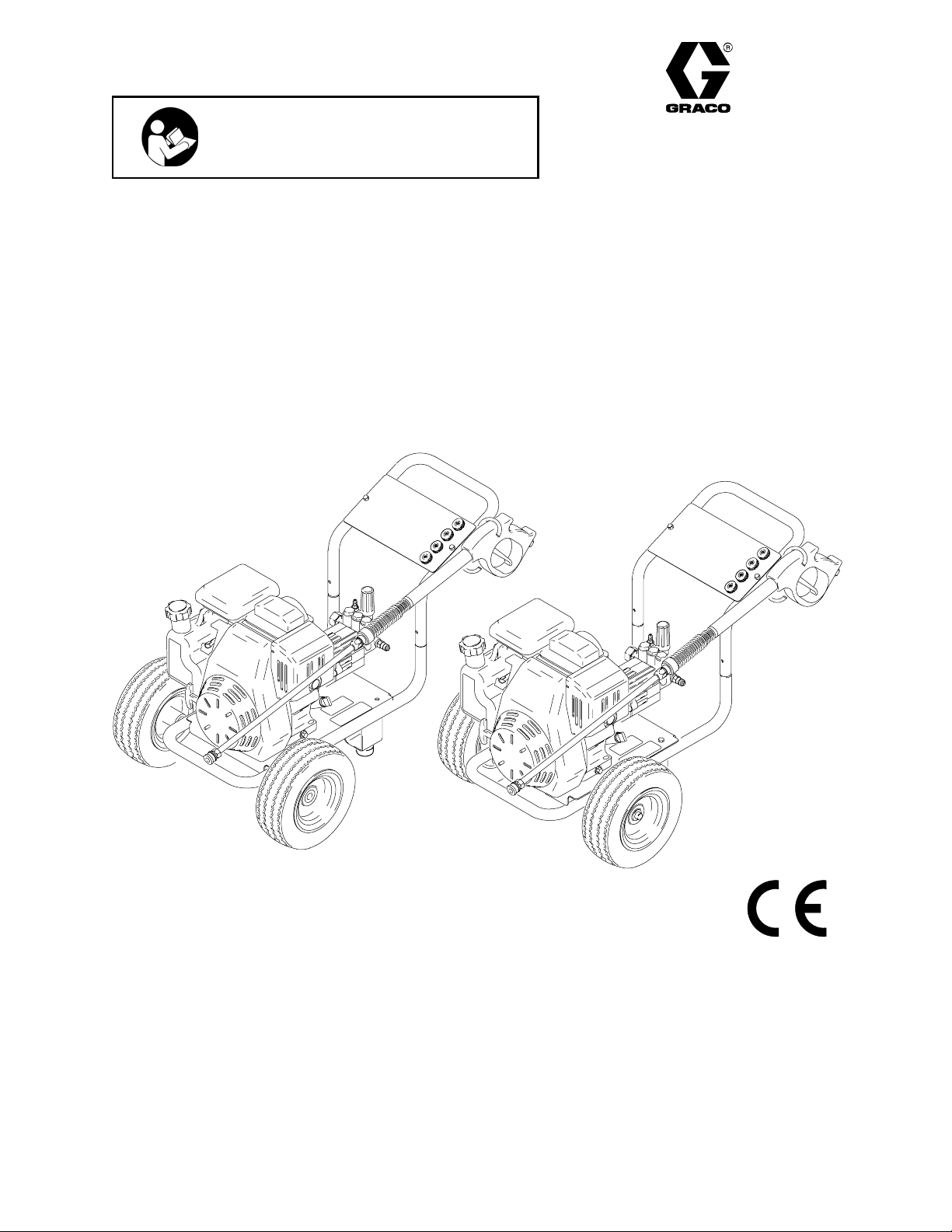
G–Force Direct-Drive Pressure Washer
2525LD
Model 246601, Series A & Series B
2300 psi (159 bar, 15.8 MPa) Maximum Operating Pressure
2500 psi (172 bar, 17.2 MPa) Maximum Working Pressure
2626LD
Model 249065, Series A
2600 psi (179 bar, 17.9 MPa) Maximum Operating Pressure
2750 psi (191 bar, 19.0 MPa) Maximum Working Pressure
2525LD
ti6075a
GRACO INC. P.O. BOX 1441 MINNEAPOLIS, MN 55440–1441
COPYRIGHT 2003 GRACO INC.
Graco Inc. is registered to I.S. EN ISO 9001
2626LD
ti3224b
Page 2

Table of Contents
Symbols 2. . . . . . . . . . . . . . . . . . . . . . . . . . . . . . . . . . . . . .
Warnings 3. . . . . . . . . . . . . . . . . . . . . . . . . . . . . . . . . . . . . .
Component Identification 4. . . . . . . . . . . . . . . . . . . . . . . .
Pressure Relief Procedure 7. . . . . . . . . . . . . . . . . . . . . . .
Installing and Changing Spray Tips 12. . . . . . . . . . . . . .
Pump Service 19. . . . . . . . . . . . . . . . . . . . . . . . . . . . . . . . .
Parts Drawing 21. . . . . . . . . . . . . . . . . . . . . . . . . . . . . . . . .
Parts List 22. . . . . . . . . . . . . . . . . . . . . . . . . . . . . . . . . . . . .
Graco Phone Number 28. . . . . . . . . . . . . . . . . . . . . . . . . .
Warning Symbol
WARNING
This symbol alerts you to the possibility of serious
injury or death if you do not follow instructions.
Caution Symbol
CAUTION
This symbol alerts you to the possibility of damage to
or destruction of equipment if you do not follow instructions.
2 309828
Page 3
FUEL HAZARD:
Fuel is combustible. When spilled on a hot surface it can ignite and cause a fire.
Do not fill fuel tank while engine is running or hot.
EXHAUST HAZARD:
Exhaust contains poisonous carbon monoxide, which is colorless and odorless. Do not operate this
equipment in a closed building.
EQUIPMENT MISUSE HAZARD:
Misuse of pressure washer or accessories can cause the equipment to rupture or malfunction and
result in serious injury.
Do not alter or modify any part or factory–setting
Check equipment daily. Repair or replace worn or damaged parts immediately.
Do not exceed maximum working pressure (MWPR) of the lowest–rated system component
Use fluids and solvents that are compatible with the equipment wetted parts. See Specifications
page for this information.
Wear hearing protection when operating this equipment.
Do not “blow back” fluid; this is not an air spray system
Follow Pressure Relief, page 7 before cleaning, checking or servicing equipment.
TOXIC FLUID HAZARD:
Hazardous fluid or toxi fumes can cause serious injury or death if splashed in eyes or on skin,
inhaled, or swallowed.
Know specific hazards of fluids you are using and take protective measures as recommended by
the fluid and solvent manufacturer.
SKIN INJECTION HAZARD:
Spray from gun, leaks or ruptured components can inject fluid into your body and cause serious
injury. Fluid splashed in eyes or on skin can also cause serious injury.
Fluid injected into skin might look like just a cut, but it is a serious injury. Get immediate
surgical treatment.
Do not point gun at anyone or any part of the body.
Do not stop or deflect leaks with hand, body, glove, or rag.
Do not put your hand or fingers over the spray tip.
TIghten fluid connections before you start this equipment.
Engage the gun safety whenever you stop spraying.
Follow Pressure Relief Procedure, page 7 if the spray tip clogs and before you clean, check
or service this equipment.
Repair or replace worn or damaged parts immediately.
Check hoses, tubes, and couplings daily. Do not repair high–pressure couplings. Replace entire
hose. Fluid hoses must have spring guards on both ends to prevent kinks and rupture.
3309828
Page 4
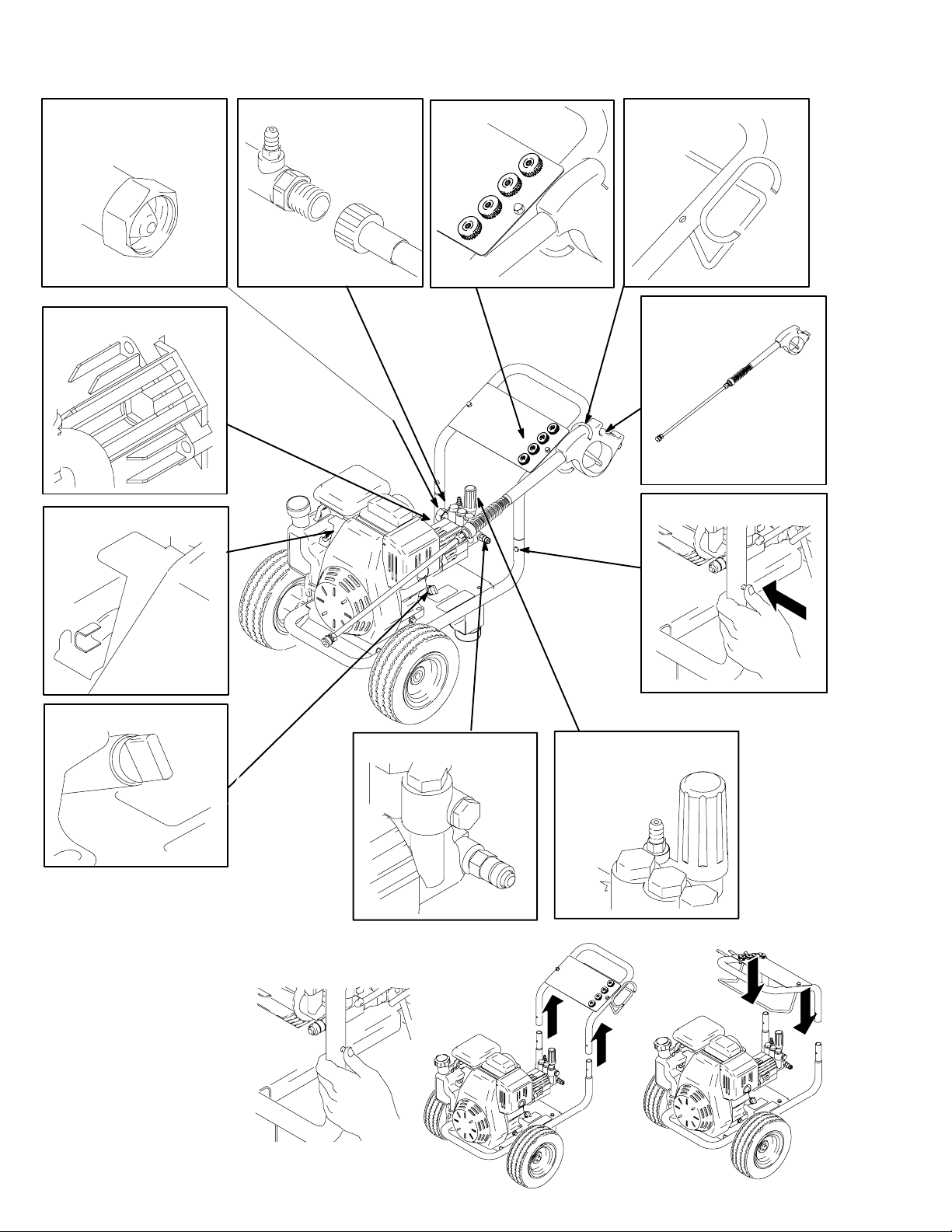
Component Identification
Garden Hose
Connection
Water Pump Oil Fill
On/Off Engine Switch (side)
High Pressure
Hose Connection
Tip Storage
Hose Rack (a) /
Gun Holder (b)
(b)
Gun and Wand
Handle Release Button*
(a)
Engine Oil Fill
*Cart handle can be removed to create a compact profile for storage
and transporting. Push
in release button on
each side of handle.
(Fig. 1) Pull handle off
lower frame. (Fig. 2).
Rotate handle 180 and
reposition over lower
frame. (Fig. 3) Push
down on handle until until release buttons engage.
4 309828
Fig. 1
ti3226a
Thermal Valve
Fig. 2
Pressure Unloader
Adjustment Knob
Fig. 3
ti6079a
ti6077a
Page 5
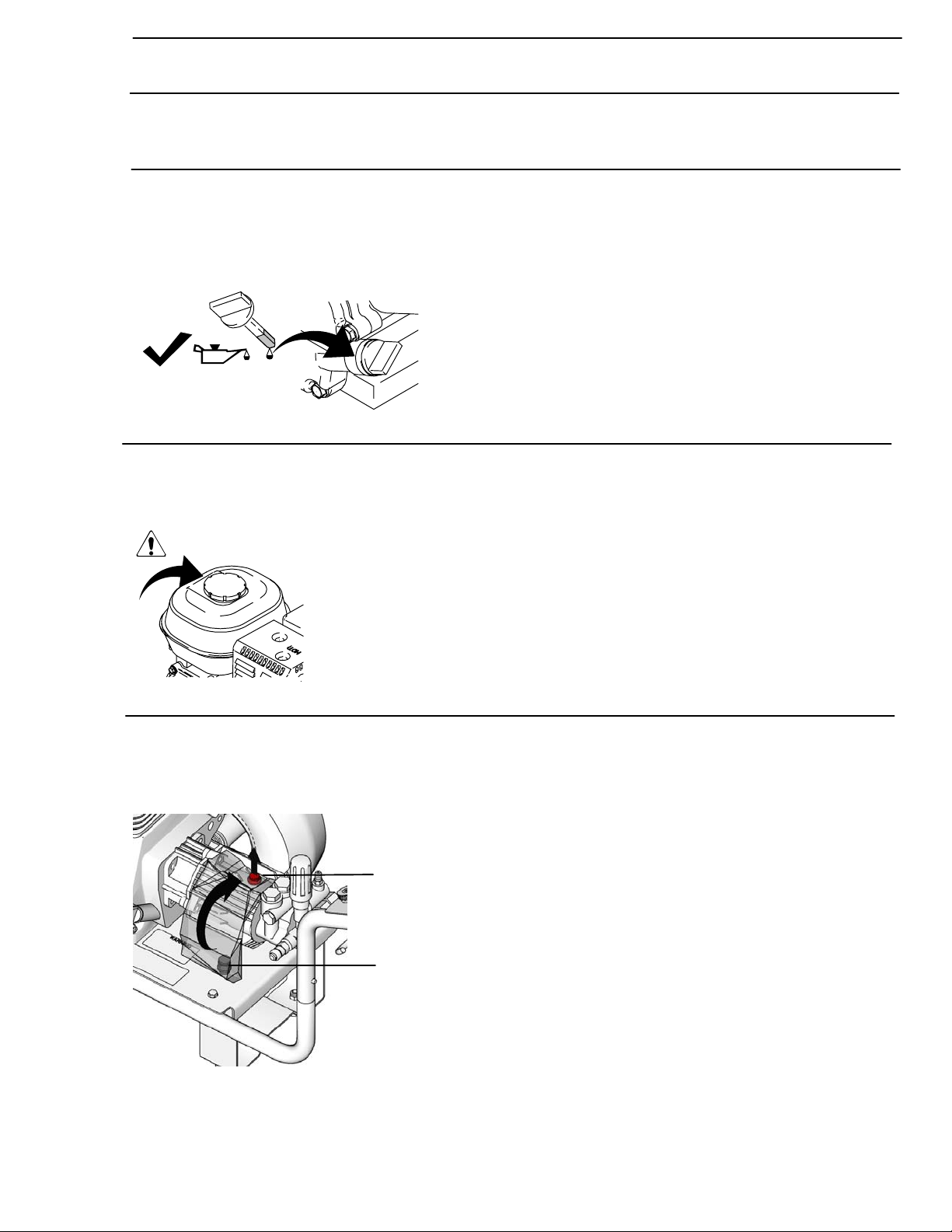
Initial Setup
Shipping Damage
Check pressure washer for shipping damage. Notify carrier immediately if there is any damage.
Oil
Engine is shipped without engine oil. Add Graco SAE 10W–30 engine oil (included) and confirm oil level is within
an acceptable range according to the Honda Owner’s Manual (included).
(cold)
ti5952a
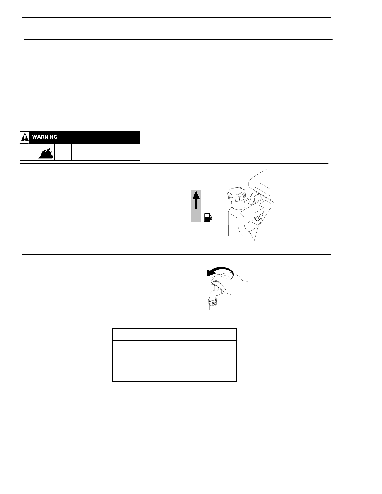
Fuel
Fill fuel tank.
ti5953a
Pump plug
Remove red water pump plug (A) and replace with attached black vented pump plug (B).
TI10675A
Red water pump plug
Black vented pump plug
5309828
Page 6
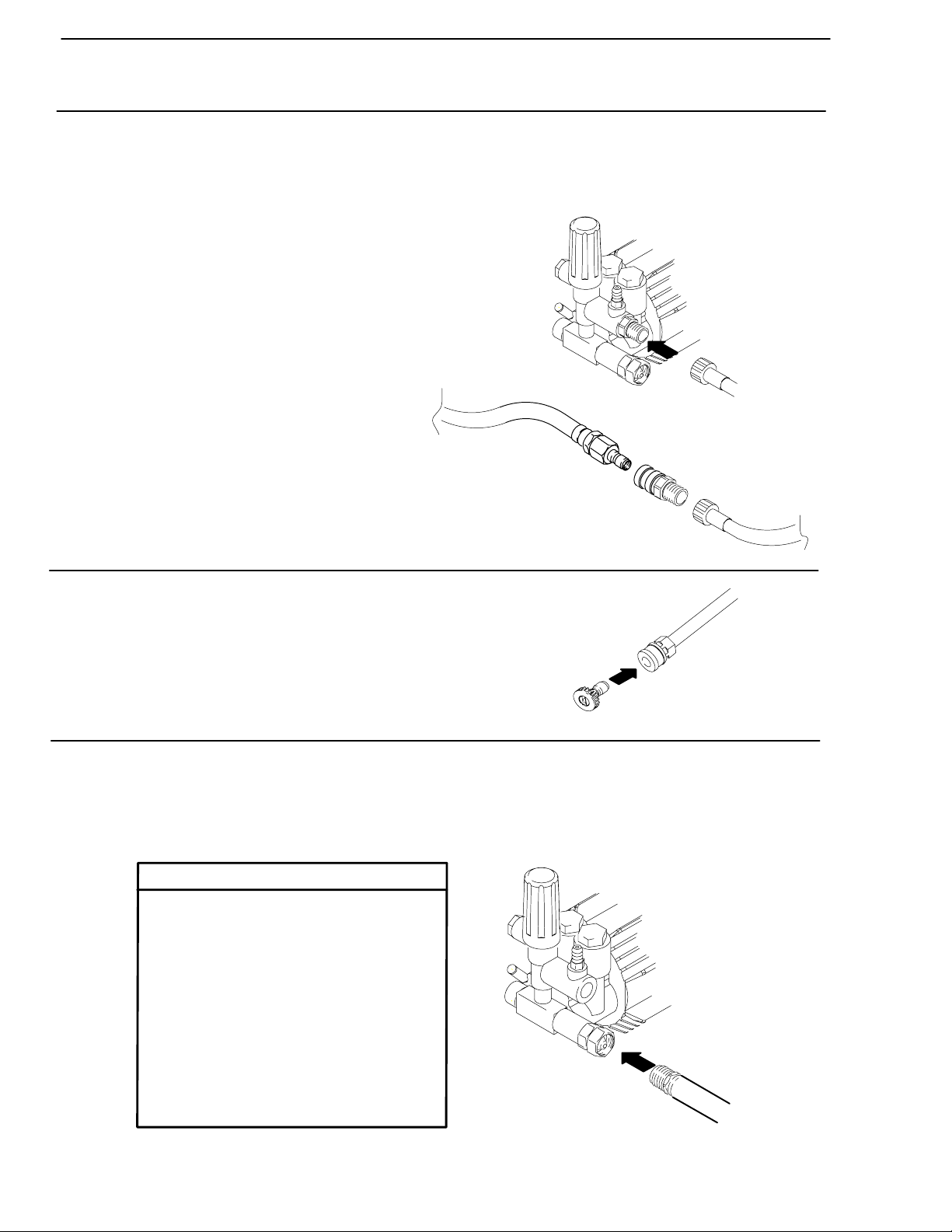
Installation
Connect High–Pressure Hose and Gun
Connect high–pressure hose between the pump outlet and gun inlet.
Both of these connections are made with quick couplers.
Note: Adapter kit 249101 can be used to connect
two high pressure hoses together.
Install Spray Tip
Install spray tip on wand. Installing and Changing Spray Tips,
page 12). If you are using a Sandblasting Kit, see its separate
manual for installation instructions.
Connect to Water Supply
Connect hose with at least a 3/4 in. (19 mm) ID from water supply
to 3/4 in. garden hose inlet on the pressure washer. The supply
hose should not be more than 50 ft (15 m) long.
ti3457a
ti7345a
ti3228a
CAUTION
Before you connect garden hose to pressure washer, check local plumbing codes
regarding cross–connection to water
supply. If required, install backflow preventer.
If inlet water pressure is over 60 psi (4.1
bar), a regulating water valve must be
installed at garden hose connection.
Do not exceed 104° F (40° C) inlet water
temperature.
Note: Water source must have a minimum flow rate equal to that of pressure washer.
ti3229a
6 309828
Page 7
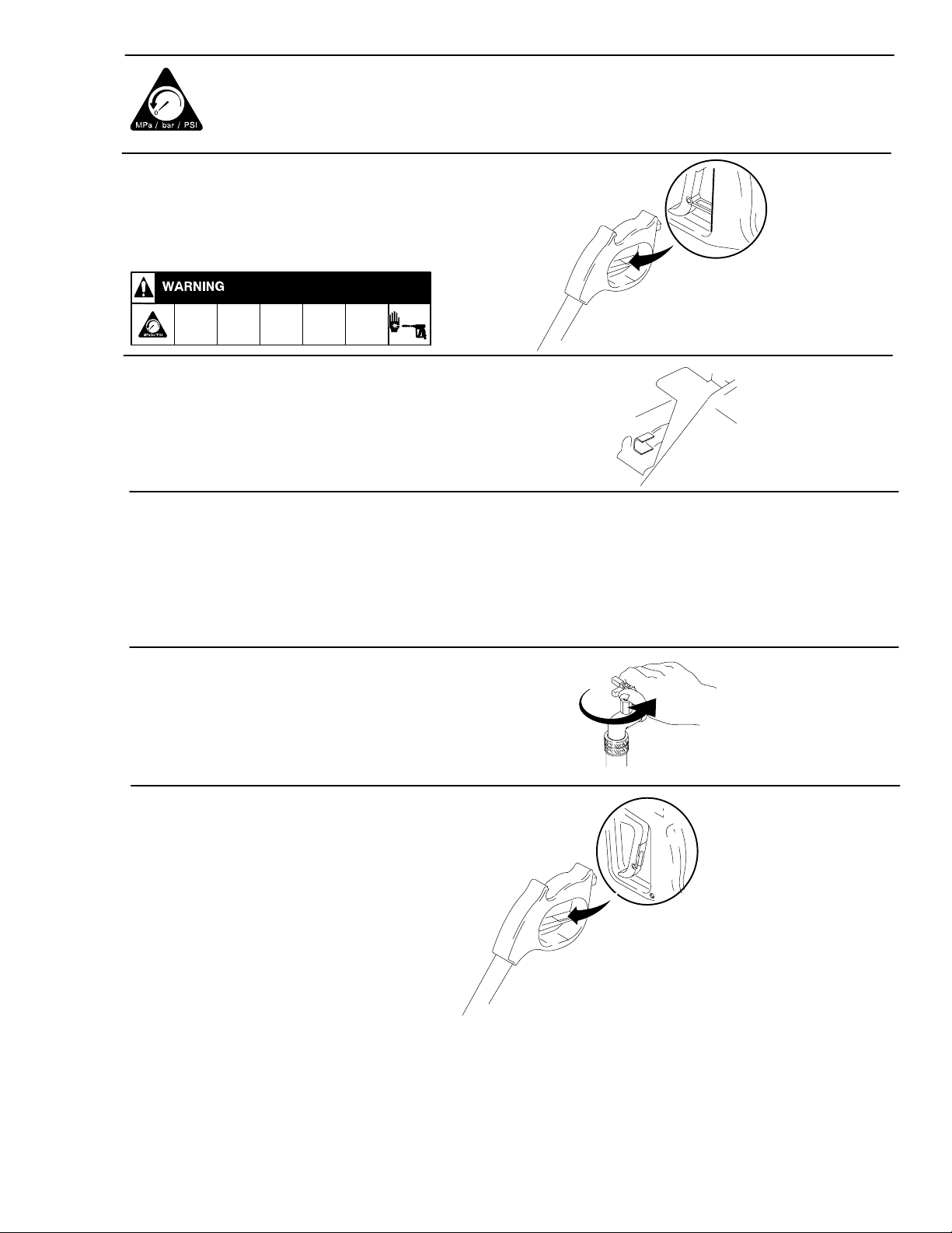
PRESSURE RELIEF
Follow these instructions whenever you are instructed to relieve pressure, stop spraying for
more than 10 minutes, check or service the equipment, or install or clean the spray nozzle.
1. Engage trigger safety latch
2. Turn pressure washer off
3. Remove ignition cable from spark plug.
TI3233A
4. Shut off water supply. Disconnect from water.
5. Disengage trigger safety latch. Trigger gun to relieve
pressure. Then re–engage the safety latch.
TI3234a
Note: If you suspect that the spray tip or hose is clogged or that pressure has not been fully relieved after
following the steps above, disengage the trigger safety latch and trigger the gun to relieve pressure.
7309828
Page 8
Operation
Startup
Always use this startup procedure to ensure that the pressure washer is started
safely and properly.
Always engage gun trigger safety latch when you stop spraying. This reduces the risk of fluid injection or
splashing in eyes or on skin if gun is bumped or accidentally triggered.
Always observe the CAUTIONS in this section to avoid costly damage to pressure washer.
If you use the Sandblaster Kit, see Sandblaster Kit Manual for detailed cleaning information.
1. Check oil level of engine.
2. Check fuel level.
3. Turn on water supply.
.
8 309828
CAUTION
Never run pressure washer without water. Costly pump damage will result.
Always be sure water supply is completely turned on before you run pressure
washer.
Page 9
4. Trigger gun until a constant stream of water sprays from tip indicating air is purged from the system.
5. Be sure spark plug ignition cable is pushed firmly onto spark plug.
6. For Model 2525LD ONLY, move
throttle to Rabbit (fast) position first.
All models
Model 2525 Only
For all models, (then) move choke to
CHOKE position.
ti3242a
7. Pull the starter rope quickly to start the engine. Pull and return the
rope until the engine starts. HINT: Placing one foot on the pressure washer as a brace provides better leverage.
NOTE: For easier starting, have one person start pressure washer while another triggers gun.
CAUTION
Do not allow pressure washer to idle more than 10
minutes. This causes circulating water to overheat and
serious damage to the pump. The pump is equipped
with a thermal valve to help prevent severe damage if
circulating water is overheating.
Turn off pressure washer if it will not be spraying at
least every 10 minutes or if thermal valve activates. If
heated inlet water is used, reduce this time.
Do not operate pressure washer with inlet water
screen removed. This screen helps keep abrasive
sediment which could clog pump or damage cylinders,
out of pump.
Do not pump caustic materials.
ti3240a
9309828
Page 10

Trigger Safety Latch
Always engage the safety latch when you stop spraying.
Always engage trigger safety latch when you stop spraying even for a moment. The engaged
safety latch prevents the gun from being triggered accidentally by hand or when dropped or
bumped. Be sure latch is pushed fully down or it will not prevent the gun from being triggered.
Safety ON
TI3233A
Safety OFF
TI3234a
10 309828
Page 11

Chemical Injector Operation
1. Follow Pressure Relief Procedure, page 7.
2. Push end of chemical injector hose over chemical injector fitting on
pump. Place other end in container of chemical solution.
3. Install the black, large–orifice, chemical tip. (Installing and Changing Spray Tips page 12).
4. Trigger gun for a few seconds. Chemical solution will begin mixing in spray pattern.
ti3237b
The large orifice of the chemical tip causes a drop in pressure that actuates the chemical injector.
Changing back to a small orifice spray tip deactivates the chemical injector and produces high pressure
for rinsing. The chemical filter can be left in the chemical container during high–pressure use.
11309828
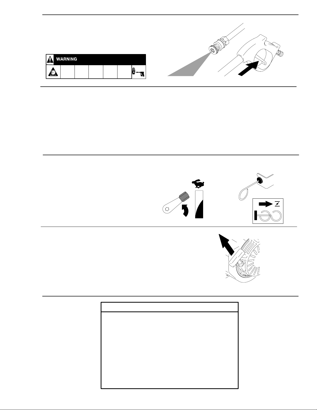
Page 12

Installing and Changing Spray Tips
Spray tips have 4– or 5–digit numbers on them.
The first two digits are the spray angle. Tip
holding holes are provided on the chassis.
Spray Tip
Number
00XXX
15XXX
25XXX
Spray Pattern Fan Angle
0 blaster (red)
15 (yellow)
25 (green)
40XXX
Chemical
NOTE: The chemical injector tip is brass and has a large opening and a black plastic cap.
1. Perform Pressure Relief Procedure, page 7.
2. Point the gun and wand away from you and anyone else.
3. Without holding your hand over spray tip (A), pull back quick
coupler ring (B). Remove current tip. Install a different one.
Then push the ring back on.
40 (white)
XX (black)
B
A
12 309828
CAUTION
To avoid blowing the o–ring out of the
quick coupler due to the high pressure in
the system, never operate pressure
washer without a tip securely mounted in
quick coupler.
Page 13

Shutdown, Flushing, and Storage
1. Remove chemical injector hose from pump, if attached.
2. Trigger gun for one minute to flush pump with clear water.
3. Engage trigger safety.
TI3233A
4. For model 2525LD, adjust throttle to STOP position. Engine
should turn off.
For model 2626LD, turn OFF power switch.
13309828
Page 14

5. Shut off water supply. Disconnect water supply hose from pump.
6. Remove trigger safety latch and trigger gun to relieve pressure.
7. Remove high pressure hose from pump. Drain water from all components.
ti3231a
TI3234a
After each use, wipe all surfaces of pressure washer with a clean, damp cloth.
ti3247b
ti3245b
14 309828
Page 15

Long Term (more than 30 days)/Winter Storage
Do not store unit outside where it can be exposed to rain, dirt or adverse weather conditions.
Do not expose pressure washer to freezing temperatures or allow water to freeze in pressure washer
components, causing the pump to lock–up. If this happens let pump thaw naturally in WARM ENVIRONMENT. DO NOT attempt to to speed up this process by pouring warm water on pump. This could
cause further damage.
ENGINE:
1. Run engine until gas is gone or stabilize the fuel and run it through the fuel system and carburetor.
2. Drain water out of pressure washer hose.
3. Turn fuel system to OFF position.
Pump:
1. Attach one end of a 4 or 5–foot section of hose to pump inlet and other end in an antifreeze solution approximately 1–foot off the ground.
2. Pull pull–cord on engine until antifreeze comes out of pump outlet.
Storage Location:
1. Store pressure washer in garage, basement or other area where it is protected from freezing temperatures.
15309828
Page 16

Maintenance Chart
Perform Pressure Relief Procedure (page 7).
Interval What to do
Daily Clean water inlet screen and filter. Check engine and pump oil levels. Fill as necessary. Check
gasoline level. Fill as necessary.
After first
5 hours of
operation
Every 3
months or
25 hours of
operation
Change engine break-in oil. Drain oil when warm. Use SAE 30 or 10W–30 detergent oil.
Clean and remove air cleaner foam. Wash with water and detergent. Dry thoroughly. Rub with
oil, and squeeze to distribute oil.
Every 6
months or
50 hours of
operation
After every
100 hours of
operation, or
every 3 months
NOTE: It is not necessary to change pump oil during the life of the pump. If pump oil is drained for repair, use part
number 117784 replacement oil only.
Change engine oil. Use approved SAE30 or 10W30 detergent oil.
Check/adjust spark plug and idle speed. Clean fuel tank and filter..
16 309828
Page 17

Troubleshooting
roughly
Perform Pressure Relief Procedure (page 7).
Problem Cause Solution
Engine will not start or
is hard to start.
Engine misses or
lacks power
Pressure is too low
and/or pump runs
Water leaks from
under pump manifold
Water on oil side of Worn packings Install new packings.
pump
No gasoline in fuel tank or carburetor Fill tank with gasoline, open fuel shutoff valve.
Check fuel line and carburetor.
Low oil Add oil to proper level.
Throttle in STOP position (model
2525LD only)
Water in fuel or old fuel Drain fuel tank and carburetor. Use new fuel
Engine flooded or improperly choked Open choke, pull engine starter rope several
Dirty air cleaner filter Remove and clean.
Spark plug dirty, wrong gap, or wrong
type
Gun not triggered Trigger gun while starting engine.
Partially plugged air cleaner filter Remove and clean.
Spark plug dirty, wrong gap, or wrong
type
Worn or wrong size tip Replace with tip of proper size.
Inlet filter clogged Clean. Check more frequently.
Worn packings, abrasives in water, or
natural wear
Inadequate water supply Check water flow rate to pump.
Fouled or dirty inlet or discharge valves Clean inlet and discharge valve assemblies.
Restricted inlet Garden hose might be collapsed or kinked.
Worn inlet or discharge valves Replace worn valves.
Leaking high–pressure hose Replace high–pressure hose.
Worn packings Install new packings.
Loose fitting connections Check all fitting connections. TIghten if loose.
Oil seals leaking Install new oil seals.
Move throttle to FAST (rabbit) position
andmake sure spark plug is dry.
times to clear out fuel. Make sure spark plug
is dry.
Clean, adjust gap or replace.
Clean, adjust gap or replace.
Check filter. Replace packing.
Check filter.
17309828
Page 18

Problem
prematurely
prematurely
Packings are failing
frequently or
Strong surging at inlet
and low pressure on
discharge side
Water spitting out of
thermal valve
Note: For complete pump repair and design information see website: www.ARNORTHAMERICA.com
Scored, damaged, or worn plungers Install new plungers.
Abrasive material in fluid being pumped Install proper filtration on pump inlet plumbing.
Inlet water temperature too high Check water temperature. It should not
Overpressurizing pump Do not modify any factory–set adjustments.
Excessive pressure due to partially
plugged or damaged tip
Pump running too long without spraying Never run pump more than 10 minutes without
Running pump dry Do not run pump without water.
Foreign particles in inlet or discharge
valve or worn inlet and/or discharge
valves
Pump running too long without spraying Trigger gun to get fresh, cooler water in pump.
Cause Solution
exceed 160F (70C).
Clean or replace tip. See Installing and
Changing Spray Tips (page 12).
spraying.
Clean or replace valves.
18 309828
Page 19

Pump Service
Repair kits are available. See the Parts Lists (page 21). For the best results, use all parts in the kits.
Perform Pressure Relief Procedure (page 7).
Servicing Valves
Discharge Valves:
Disassembly
1. Remove valve cap.
2. Inspect valve cap o–ring for damage. Replace if
necessary.
3. Using a needle nose pliers, remove valve.
4. Use a small probe to move the poppet up and down
to assure it is functioning properly.
5. Inspect for any debris that may be lodged between
poppet and seal.
6. Remove valve seat o–ring and inspect for damage.
Assembly
Inlet Valves
Disassembly
1. Remove manifold.
2. Remove low–pressure seals by inserting a flat
screwdriver under seal lip and lifting up.
3. Using a reversible pliers, carefully remove packing
retainers (plunger guides).
Note: Packing retainers can be reused if not worn.
4. Remove high–pressure packing by pulling straight
out with your finger.
5. Pull out valve cage/head ring assembly, valve
poppet, spring and o–ring.
6. Inspect for debris and/or damage.
7. Remove valve o–ring.
Assembly
1. Install valve seat o–ring squarely into bottom of
manifold.
2. Insert valve assembly and push squarely into
o–ring.
3. Install high–pressure packing by placing it into
cylinder at an angle and then pushing into place.
Note: The point of the “v” or flat side of packing is
pointed at you.
4. Lubricate packing retainer o–ring with a light film of
oil and install it into cylinder.
1. Install valve seat o–ring squarely into bottom of
manifold.
2. Insert valve assembly squarely into port, pushing it
into o–ring.
3. Install valve cap and torque to 443 in.–lbs (37
ft–lbs).
5. Push it completely into place.
Note: O–ring will seat just inside manifold and you will
hear a slight pop.
6. Insert low–pressure seal by placing it into cylinder
at an angle and pushing it into place.
7. Put a thin coat of oil on plungers and packings.
8. Carefully install manifold and torque bolt to 443
in.–lbs (37 ft–lbs).
Note: Valve life is dependant on many variables.
Hard water, cavitation, corrosion, chemicals and
equipment care. The valves are a wear item and need
periodic replacement. Worn o–rings or damaged
valves will cause pressure loss and pulsations.
19309828
Page 20

Packings
Disassembly
1. To access water seals for inspection or replacement, remove head of pump.
Assembly
1. Install high–pressure seal into head.
Note: It is important to note the order in which the
components of the packing stack are arranged and
facing during disassembly.
2. Remove head bolts.
3. Insert a small pry bar between head and body at
opposite corners and apply pressure down on one
pry bar and up on the other pry bar.
4. Lift head up and away from body.
Note: Packing stack will not always stay in head of
pump when it is removed. Sometimes one or more
components of the packing stack will come out of the
head and stay on the plunger.
5. To remove any components that stay on plungers
twist back and forth while pulling up.
6. Remove low–pressure seals by inserting a flat
screwdriver under seal lip and lifting up.
7. Remove piston guides from head by using a reverse pliers (preferably rubber coated) inserted
into center of piston guide.
8. Use back and forth twisting motion while pulling up
(clockwise and counter–clockwise).
Note: It should fit snugly. The packing support is part
of the valve cage.
2. Place high–pressure seal at an angle and work it
into cylinder.
Note: The point of the “v” or flat side of packing is
pointed at you.
3. Lubricate packing retainer o–ring with a light film of
oil and install it into cylinder.
4. Push it completely into place.
Note: O–ring will seat just inside manifold and you will
hear a slight pop.
5. Insert low–pressure seal by placing it into cylinder
at an angle and pushing it into place.
6. Put a thin coat of oil on plungers and packings.
7. Carefully install manifold and torque bolt to 443
in.–lbs (37 ft–lbs).
9. Another method is to use a two–prong slide hammer puller. Insert prongs into piston guide allowing
prongs to grab under support ring, then use slide
hammer to pull packing stack up and out of head.
Note: Damage to piston guides and or seals may
occur during removal. Inspect carefully before reusing
any components of packing stack.
10. Remove high–pressure packing by pulling straight
out with your finger.
Note: Valve life is dependant on many variables.
Hard water, cavitation, corrosion, chemicals and
equipment care. The valves are a wear item and need
periodic replacement. Worn o–rings or damaged
valves will cause pressure loss and pulsations.
Water seals are wear items. Lift of seals is dependent
on many factors. Water seals should be replaced
when water leak or loss of performance is noticed.
Prompt replacement of worn seals will insure peak
operating performance and trouble–free operation.
20 309828
Page 21

Parts
Model 2525LD
20 23
45
22
24
43,44
25
40
21
33
31
4
2
26
35
10
12
32
34
5
9
6
7
8
27
3
1
29
30
28
56
13
14
22
ti7343a
15
36
16
17
21309828
Page 22

Parts
Model 2525LD
Ref.
Part
No.
No.
1 15C311 HANDLE, cart 1
2 15B880 FRAME, placard 1
3 15C307 RACK, hose 1
4 115651 NUT, acorn 2
5 805535 TIP, 0°, red 1
6 805536 TIP, 15°, yellow 1
7 805538 TIP, 40°, white 1
8 805634 TIP, chemical, black 1
9 801012 GROMMET 4
10 112827 BUTTON, snap 2
12 15C309 FRAME, cart, Series A 1
287611 FRAME, cart, Series B 1
13 116968 WHEEL 2
14 101242 RING, retaining 2
15 15C305 FRAME, leg. Series A 1
287609 FRAME, leg. Series B 1
16 113817 FOOT, base, rubber 2
17 100057 SCREW, hex, cap 2
Description Qty.
Ref.
Part
No.
No.
20 118000 ENGINE, 5 hp, Honda 1
21 110837 SCREW, hex hd 4
22 111040 NUT, nylon 6
23 197792 KEY, motor shaft 1
24 287137 PUMP (with bolts) 1
25 117758 ADAPTER, garden hose 1
26 117759 VALVE, thermal 1
27 117760 HOSE, injector 1
28 118125 HOSE 1
29 246674 GUN 1
30 118124 EXTENSION, gun 1
31 116477 WASHER 2
32 290013 LABEL, warning 1
33 290131 LABEL, warning 1
34 802363 LABEL, caution 1
35 100270 SCREW, cap, hex hd 2
36 102040 NUT, lock 2
40 116411 SPRING 2
45 100527 WASHER 4
55 249101 KIT, coupling, hose (see
56 113418 O–RING 1
Y Additional danger and warning tags and labels
available free.
Description Qty.
page NO TAG)
1
22 309828
Repair parts for Honda Engine model GC160, 5
hp, can be identified and purchased by following the
links on our website: www.graco.com.
Page 23

SJV2.5G25D–F7
(Use with model 2525LD)
1
2
3
5
6
8
9
10
11
12
13
14
15
16
17
18
19
21
23
4
6
7
5
26
24
25
Repair Kits
57
48
30
31
32
27
28
40
33
34
35
36
47
46
49
62
44
43
45
41
37
38
55
63
66
ti6080c
SJV2.5G25D–F7 Repair Kits
287572 KIT, repair, water seals
includes 41, 43, 44, 45, 62
287132 KIT, repair, valves
includes 12, 28, 40
287133 KIT, repair, pistons
includes 55
287134 KIT, repair, oil seals
includes 46, 57, 66
287135 KIT, repair, o–rings
includes, 9, 10, 12, 13, 14,
15, 16, 19, 21, 27, 30, 31,
32, 33, 36, 37, 49, 63
287874 KIT, chemical injector, 33,
1
34, 35, 36, 37, 38
287136 KIT, repair, unloader
1
includes 1–19
1
1
287137 PUMP (complete pump) 1
1
1
Additional repair parts for AR North American
117784 OIL, pump 1
pump model SJV2.5G25D–F7, can be identified and
1
purchased by following the links on our website:
www.graco.com.
23309828
Page 24

Parts
Model 2626LD
20 23
45
22
24
43,44
25
21
33
4
2
26
35
10
12
32
34
5
9
6
7
8
27
3
1
29
30
28
56
13
22
40
14
31
ti7344a
15
36
16
17
24 309828
Page 25

Parts
Model 2626LD
Ref.
Part
No.
No.
1 15C311 HANDLE, cart 1
2 15F136 FRAME, placard 1
3 15C307 RACK, hose 1
4 115651 NUT, acorn 2
5 805535 TIP, 0°, red 1
6 805536 TIP, 15°, yellow 1
7 805538 TIP, 40°, white 1
8 805634 TIP, chemical, black 1
9 801012 GROMMET 4
10 112827 BUTTON, snap 2
12 287611 FRAME, cart 1
13 116968 WHEEL 2
14 101242 RING, retaining 2
15 287609 FRAME, leg 1
16 113817 FOOT, base, rubber 2
17 100057 SCREW, hex, cap 2
Description Qty.
Ref.
Part
No.
No.
20 119587 ENGINE, 6 hp, Honda 1
21 110837 SCREW, hex hd 4
22 111040 NUT, nylon 6
23 197792 KEY, motor shaft 1
24 287574 PUMP (with bolts) 1
25 117758 ADAPTER, garden hose 1
26 117759 VALVE, thermal 1
27 117760 HOSE, injector 1
28 118125 HOSE 1
29 246674 GUN 1
30 118124 EXTENSION, gun 1
31 116477 WASHER 2
32 290013 LABEL, warning 1
33 290131 LABEL, warning 1
34 802363 LABEL, caution 1
35 100270 SCREW, cap, hex hd 2
36 102040 NUT, lock 2
40 116411 SPRING 2
45 100527 WASHER 4
55 249101 KIT, coupling, hose (see
56 113418 O–RING 1
Y Additional danger and warning tags and labels
available free.
Description Qty.
page NO TAG)
1
Repair parts for Honda Engine model GC190, 6
hp, can be identified and purchased by following the
links on our website: www.graco.com.
25309828
Page 26

SJV2.5G27–D105
(Use with Model 2626LD)
1
2
3
5
6
8
9
10
11
12
13
14
15
16
17
18
19
21
23
4
6
7
5
26
27
28
24
33
25
34
Repair Kits
48
30
31
32
41
40
35
36
37
47
46
49
62
44
43
45
38
55
63
66
ti6163b
SJV2.5G27–D2105 Repair Kits
287572 KIT, repair, water seals
includes 41, 43, 44, 45, 62
287132 KIT, repair, valves
includes 12, 28, 40
287133 KIT, repair, pistons
includes 55
287573 KIT, repair, oil seals
includes 46, 47, 66
287135 KIT, repair, o–rings
includes, 9, 10, 12, 13, 14,
15, 16, 19, 21, 27, 30, 31,
32, 33, 36, 37, 49, 63
287874 KIT, chemical injector, 33,
1
34, 35, 36, 37, 38
287136 KIT, repair, unloader
1
includes 1–19
1
1
287574 PUMP (complete pump) 1
1
1
Additional repair parts for AR North American
117784 OIL, pump 1
pump model SJV2.5G27–D2105, can be identified and
1
purchased by following the links on our website:
www.graco.com.
26 309828
Page 27

Technical Data
Model 2525LD
Working pressure range
Operating Pressure 2300 psi (159 bar, 15.8 MPa)
Maximum Working Pressure 2500 psi (172 bar, 17.2 MPa)
Engine horsepower 5.0
Maximum delivery (with nozzle) 2.5 gpm
High pressure hose 30 ft x 5/16 in. supplied
Chemical injector hose 4 ft ( m) 1/4 in. ID
Weight, pressure washer only 60 lb (27.22 kg)
Weight: sprayer, hose and gun 73 lb (33.11 kg)
Dimensions
23.5 in. (59.69 cm) Length
22.0 in. (55.88 cm) Width
22.0 (55.88 cm) Height
Pump inlet fitting 3/4 in. internal thread (standard garden hose thread)
Storage temperature range* –30 to 160F (–35 to 71C)
Operating temperature range 40 to 115F (4 to 46C)
Sound data Sound pressure: 92.5 dB(A)
Sound level: 106.8 dB(A)
*When pump is stored with non–freezing fluid.
Model 2626LD
Working pressure range
Operating Pressure 2600 psi (179 bar, 17.9 MPa)
Maximum Working Pressure 2750 psi (190 bar, 19.0 MPa)
Engine horsepower 6.0
Maximum delivery (with nozzle) 2.6 gpm
High pressure hose 30 ft x 5/16 in. supplied
Chemical injector hose 4 ft ( m) 1/4 in. ID
Weight, pressure washer only 63 lb (28.58 kg)
Weight: sprayer, hose and gun 70 lb (31.75 kg)
Dimensions
23.5 in. (59.69 cm) Length
22.0 in. (55.88 cm) Width
22.0 (55.88 cm) Height
Pump inlet fitting 3/4 in. internal thread (standard garden hose thread)
Storage temperature range* –30 to 160F (–35 to 71C)
Operating temperature range 40 to 115F (4 to 46C)
Sound data Sound pressure: 95.2 dB(A)
Sound level: 109 dB(A)
*When pump is stored with non–freezing fluid.
27309828
Page 28

Graco Standard Warranty
Graco warrants all equipment listed in this manual which is manufactured by Graco and bearing its name to be free from defects in
material and workmanship on the date of sale to the original purchaser for use. Graco will, for a period of twelve months from the date of
sale, repair or replace any part of the equipment determined by Graco to be defective. This warranty applies only when the equipment
is installed, operated and maintained in accordance with Graco’s written recommendations.
This warranty does not cover, and Graco shall not be liable for general wear and tear, or any malfunction, damage or wear caused by
faulty installation, misapplication, abrasion, corrosion, inadequate or improper maintenance, negligence, accident, tampering, or
substitution of non-Graco component parts. Nor shall Graco be liable for malfunction, damage or wear caused by the incompatibility of
Graco equipment with structures, accessories, equipment or materials not supplied by Graco, or the improper design, manufacture,
installation, operation or maintenance or structures, accessories, equipment or materials not supplied by Graco.
This warranty is conditioned upon the prepaid return of the equipment claimed to be defective to an authorized Graco distributor for
verification of the claimed defect. If the claimed defect is verified, Graco will repair or replace free of charge any defective parts. The
equipment will be returned to the original purchaser transportation prepaid. If inspection of the equipment does not disclose any defect
in material or workmanship, repairs will be made at a reasonable charge, which charges may include the costs of parts, labor, and
transportation.
Graco’s sole obligation and buyer’s sole remedy for any breach of warranty shall be as set forth above. The buyer agrees that no other
remedy (including, but not limited to, incidental or consequential damages for lost profits, lost sales, injury to person or property, or any
other incidental or consequential loss) shall be available. Any action for breach of warranty must be brought within two (2) years of the
date of sale.
GRACO MAKES NO WARRANTY, AND DISCLAIMS ALL IMPLIED WARRANTIES OF MERCHANTABILITY AND FITNESS FOR
A PARTICULAR PURPOSE IN CONNECTION WITH ACCESSORIES, EQUIPMENT, MATERIALS OR COMPONENTS SOLD BUT
NOT MANUFACTURED BY GRACO. These items sold, but not manufactured by Graco (such as electric motors, gas engines,
switches, hose, etc.), are subject to the warranty, if any, of their manufacturer. Graco will provide purchaser with reasonable assistance
in making any claim for breach of these warranties.
In no event will Graco be liable for indirect, incidental, special or consequential damages resulting from Graco supplying equipment
hereunder, or the furnishing, performance, or use of any products or other goods sold hereto, whether due to a breach of contract,
breach of warranty, the negligence of Graco, or otherwise.
FOR GRACO CANADA CUSTOMERS
The parties acknowledge that they have required that the present document, as well as all documents, notices and legal proceedings
entered into, given or instituted pursuant hereto or relating directly or indirectly hereto, be drawn up in English. Les parties
reconnaissent avoir convenu que la rédaction du présente document sera en Anglais, ainsi que tous documents, avis et procédures
judiciaires exécutés, donnés ou intentés à la suite de ou en rapport, directement ou indirectement, avec les procédures concernées.
ADDITIONAL WARRANTY COVERAGE
Graco does provide extended warranty and wear warranty for products described in the “Graco Contractor Equipment Warranty
Program”.
Graco Phone Number
TO PLACE AN ORDER, contact your Graco distributor, or call this number to identify the distributor closest to you:
1–800–690–2894 Toll Free
All written and visual data contained in this document reflect the latest product information available at the time of publication.
Graco reserves the right to make changes at any time without notice.
MM 309828
International Offices: Belgium, China, Japan, Korea
GRACO INC. P.O. BOX 1441 MINNEAPOLIS, MN 55440–1441
Graco Headquarters: Minneapolis
www.graco.com
2/2003, Rev 1/2008
28 309828
 Loading...