

Page 1
REPAIR – RÉPARATION –
REPARATUR – REPARATIE
309250 Ausg.L
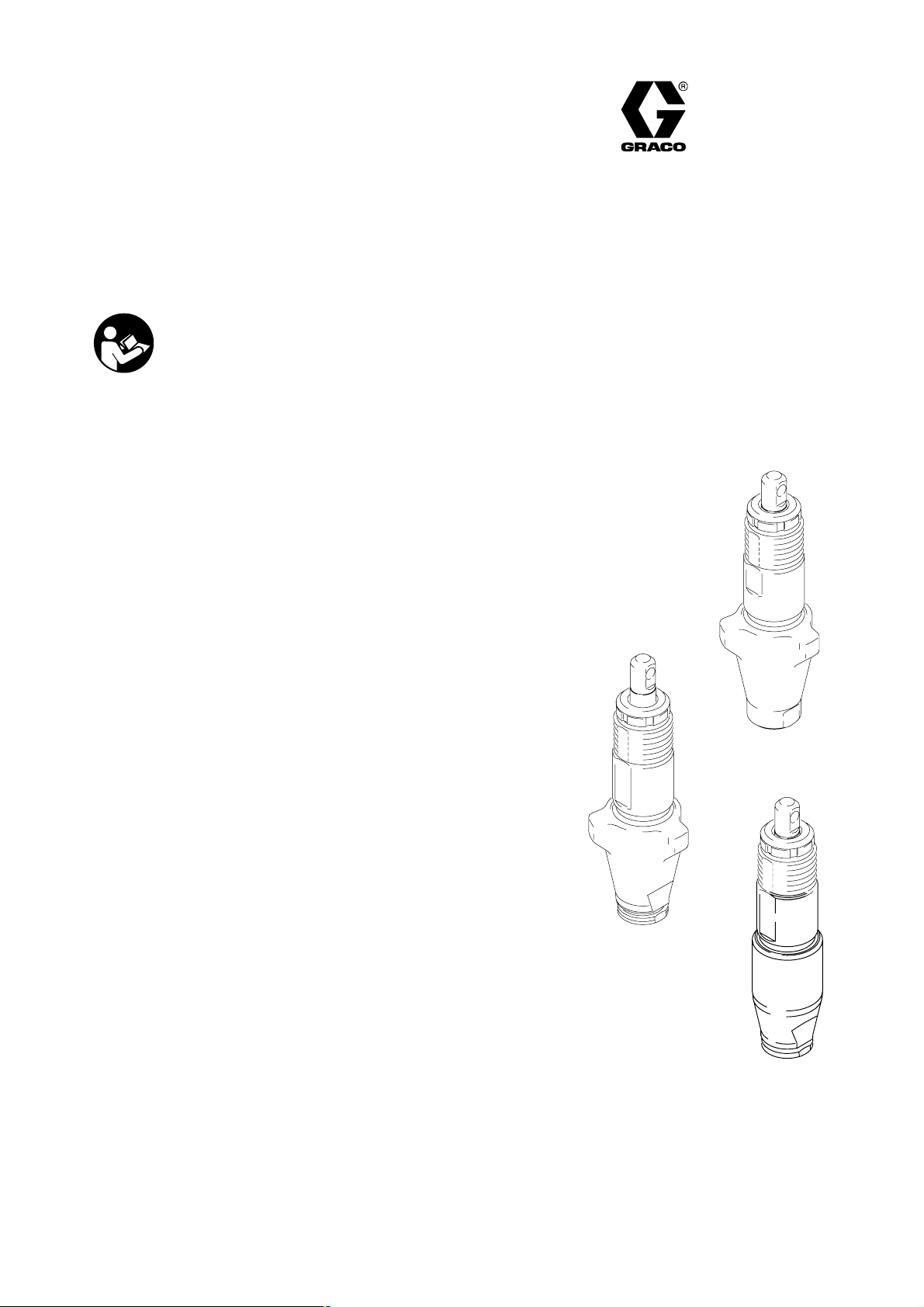
Displacement Pump / Bas de pompe
Unterpumpe / Onderpomp
Important Safety Instructions
Read all warnings and instructions in
this manual.Save these instructions.
Maximum Working Pressure / Pression de service maximum /Maximaler Arbeitsdruck
Maximum werkdruk: 228 bar (23 MPa)
Model 244195
Ultra Max 695, Series A
Ultimate Mx 695, Series A
Model 246428
Ultra 395/495/595
Ultimate NOVAt 395
Ultimate Super NOVAt 495/595
ST Max 395/495/595
Performance Max 395/495/595
Ultra Max 695, Series B
Ultra 695, Series A
Ultimate Mx 695, Series B
Ultimate 695, Series A
GMax 3400, Series A
LineLazer 3400, Series A
Ultra Max II 490/495/595, Series A
Ultimate MX II 490/495/595, Series A
ST Max II 490/495/595, Series A
390, Series A: Models 253958, 826084, 254968, 254969, 254998, 253961
246428
Model 249127
390, Series A: Models 248800, 248802, 248804, 248806, 248808, 248810, 826055
NOVA 390, Series A
244195
249127
ti6144a
GRACO N.V.; Industrieterrein — Oude Bunders;
Slakweidestraat 31, 3630 Maasmechelen, Belgium
Tel.: 32 89 770 700 – Fax: 32 89 770 777
ECOPYRIGHT 2005, GRACO INC.
Page 2
WARNING
FIRE AND EXPLOSION HAZARD
Flammable fumes, such as solvent and paint fumes, in work area can ignite or explode. To help prevent fire and
explosion:
D Use equipment only in well ventilated area.
D Eliminate all ignition sources; such as pilot lights, cigarettes, portable electric lamps, and plastic drop clothes
(potential static arc).
D Keep work area free of debris, including solvent, rags and gasoline.
D Do not plug or unplug power cords or turn lights on or off when flammable fumes are present.
D Ground equipment and conductive objects in work area. Read Grounding instructions.
D If there is static sparking or you feel a shock, stop operating immediately. Do not use equipment until you
identify and correct the problem.
INJECTION HAZARD
High pressure fluid from gun, hose leaks, or ruptured components will pierce skin. This may look like just a cut,
but it is a serious injury that can result in amputation. Get immediate medical attention.
D Do not point gun at anyone or any part of the body.
D Do not put your hand over the spray tip.
D Do not stop or deflect leaks with your hand, body, glove, or rag.
D Do not spray without tip guard and trigger guard installed.
D Engage trigger lock when not spraying.
D Follow Pressure Relief Procedure in this manual, when you stop spraying and before cleaning, checking or
servicing equipment.
MISE EN GARDE
RISQUES D’INCENDIE ET D’EXPLOSION
Les vapeurs inflammables de solvant et de peinture sur le lieu de travail peuvent prendre feu ou exploser.
Pour prévenir un incendie ou une explosion :
D N’utiliser l’équipement que dans des locaux bien ventilés.
D Supprimer toutes les source de feu, telles que les veilleuses, cigarettes, lampes électriques portatives et
bâches plastique (risque de décharge d’électricité statique).
D Veiller à débarrasser la zone de travail de tout résidu, comme les solvants, les chiffons et l’essence.
D Ne pas brancher ni débrancher de cordons d’alimentation électrique ni allumer ou éteindre la lumière en
présence de vapeurs inflammables.
D Raccorder le matériel et les objets conducteurs se trouvant dans la zone de travail à la terre. Lire les
instructions de Mise à la terre.
D Si l’on remarque la moindre étincelle d’électricité statique ou si l’on ressent une décharge électrique, arrêter
le travail immédiatement. Ne pas utiliser le matériel tant que le problème n’a pas été identifié et résolu.
DANGER D’INJECTION
Le produit s’échappant à haute pression du pistolet, d’une fuite sur le flexible ou d’un composant défectueux
risque de transpercer la peau. La blessure peut avoir l’aspect d’une simple coupure, mais il s’agit en fait d’une
blessure sérieuse pouvant entraîner une amputation. Consulter immédiatement un médecin.
D Ne pas pointer le pistolet vers une personne ou une partie quelconque du corps.
D Ne pas mettre la main devant la buse de projection.
D Ne jamais colmater ou dévier les fuites avec la main, le corps, un gant ou un chiffon.
D Ne pas pulvériser sans garde-buse ni sous-garde.
D Verrouiller la gâchette à chaque arrêt de la pulvérisation.
D Suivre la Procédure de décompression de ce manuel à chaque interruption de la pulvérisation et avant le
nettoyage, la vérification ou l’entretien du matériel.
2 309250
Page 3
ACHTUNG
BRAND- UND EXPLOSIONSGEFAHR
Brennbare Dämpfe wie z. B. Lösungsmittel- und Lackdämpfe im Arbeitsbereich können explodieren oder sich
entzünden. Durch folgende Maßnahmen kann die Brand- und Explosionsgefahr verringert werden:
D Gerät nur in gut belüfteten Bereichen verwenden.
D Mögliche Zündquellen wie z. B. Dauerflammen, Zigaretten, tragbare Elektrolampen und Plastik-Abdeckfolien
(Gefahr der Entstehung von Funkenbildung durch statische Elektrizität) beseitigen.
D Den Arbeitsbereich frei von Abfall, einschließlich Lösungsmittel, Lappen und Benzin, halten.
D Kein Stromkabel ein- oder ausstecken und keinen Lichtschalter betätigen, wenn brennbare Dämpfe vorhanden
sind.
D Geräte und elektrisch leitfähige Gegenstände im Arbeitsbereich erden. Abschnitt Erdung lesen.
D Wird bei Verwendung dieses Geräts statische Funkenbildung wahrgenommen oder ein elektrischer Schlag
verspürt, das Gerät sofort abschalten. Gerät nicht wieder verwenden, bevor nicht das Problem erkannt und
behoben wurde.
GEFAHR DURCH MATERIALEINSPRITZUNG
Eine mit Hochdruck aus Pistolen, Löchern im Schlauch oder gerissenen Komponenten austretende Flüssigkeit
kann in die Haut eindringen. Eine derartige Verletzung kann zwar wie ein gewöhnlicher Schnitt aussehen.
Tatsächlich handelt es sich dabei jedoch um eine schwere Verletzung, die eine Gliedmaßenamputation zur Folge
haben kann. Sofort einen Arzt aufsuchen.
D Die Pistole nicht gegen Personen oder Körperteile richten.
D Nicht die Hand über die Spritzdüse legen.
D Undichte Stellen nicht mit der Hand, dem Körper, einem Handschuh oder Lappen zuhalten oder ablenken.
D Niemals ohne Düsenschutz und Abzugssperre arbeiten.
D Immer die Abzugssperre verriegeln, wenn nicht gespritzt wird.
D Stets die in dieser Anleitung beschriebene Druckentlastung ausführen, wenn die Spritzarbeiten beendet
werden und bevor die Geräte gereinigt, überprüft oder gewartet werden.
WAARSCHUWING
BRAND- EN EXPLOSIEGEVAAR
Brandbare dampen in het werkgebied zoals die van oplosmiddelen en verf kunnen ontbranden of exploderen.
Voorkom brand en explosies o.a. als volgt:
D Gebruik de apparatuur alleen in goed geventileerde ruimtes.
D Zorg dat er geen ontstekingsbronnen zijn, zoals waakvlammen, sigaretten, draagbare elektrische lampen en
kunststof kleding (deze kunnen statische vonkoverslag geven).
D Houd de werkruimte vrij van afval, ook verdunning, poetslappen en benzine.
D Haal geen stekkers uit stopcontacten, steek geen stekkers in stopcontacten en doe geen lampen aan of uit als
er brandbare dampen aanwezig zijn.
D Aard de apparatuur en alle elektrisch geleidende voorwerpen en apparaten in het werkgebied. Lees de
aardingsvoorschriften.
D Als u merkt dat er sprake is van enige statische elektriciteit of u een schok voelt, zet het systeem dan
onmiddellijk uit. Gebruik het systeem pas weer als u de oorzaak van het probleem kent en het probleem
verholpen is.
INJECTIEGEVAAR
Vloeistof dat onder hoge druk uit pistool, uit lekkende slangen of uit beschadigde onderdelen komt, dringt door de
huid naar binnen in het lichaam. Dit kan eruit zien als een gewone snijwond, maar er is sprake van ernstig letsel.
Raadpleeg onmiddellijk een arts.
D De pistool niet op een persoon of enig lichaamsdeel richten.
D De hand nooit op de spuittip plaatsten.
D Nooit proberen lekkages te stoppen met uw handen, het lichaam, handschoenen of een doek.
D Niet spuiten als de tipbeveiliging en veiligheidspal van de trekker niet zijn aangebracht.
D Vergrendel de veiligheidspal van de trekker altijd wanneer u niet spuit.
D Volg altijd de Drukontlastingsprocedure in deze handleiding wanneer u ophoudt met spuiten, vóór reiniging,
controle, of onderhoud aan de apparatuur.
3309250
Page 4

PRESSURE RELIEF / DÉCOMPRESSION / DRUCKENTLASTUNG / DRUKONTLASTINGSPROCEDURE
Follow 1–5 when you
stop spraying.
Suivre les étapes 1 à 5
lorsqu’on arrête de
pulvériser.
Schritte 1–5 ausführen, wenn
die Spritzarbeiten beendet
werden.
Voer stappen 1–5 uit wanneer
u stopt met spuiten.
3
12
4
DISASSEMBLE / DEMONTAGE / ZERLEGEN / DEMONTEREN
oder
of
or
ou
1253
5
244195
246428 249127
4
or
ou
oder
of
TI0781A
4 309250
7571a
ti2776a
COMPONENT DAMAGE HAZARD
RISQUE DEDÉTÉRIORATION
DES COMPOSANTS
GEFAHR DER
TEILEBESCHÄDIGUNG
GEVAAR VAN SCHADE AAN COMPONENTEN
Do not clean piston valve threads. Cleaning piston valve threads
could destroy thread locking patch and cause piston valve to come
loose during operation, causing pump damage and possible serious
injury.
Ne pas nettoyer les filets du clapet piston. Un tel nettoyage pourrait
détruire l’enduit frein des filets et causer la dislocation du clapet
piston en fonctionnement, entraînant ainsi l’endommagement de la
pompe et des blessures graves.
Das Gewinde des Kolbenventils nicht reinigen. Das Reinigen des
Kolbenventilgewindes könnte die Gewindesicherung zerstören und
dazu führen, dass sich das Kolbenventil während des Betriebes
lockert, was zu einer Beschädigung der Pumpe sowie zu schweren
Körperverletzungen führen kann.
Maak de schroefdraad van de zuigerklep niet schoon. Hierdoor kan
namelijk het draadborgmiddel beschadigd raken, waardoor de zuiger
tijdens het werken los zou kunnen komen. Dat zou de pomp beschadigen en kan ernstig letsel veroorzaken.
WARNING
WARNUNG /
TI779A
/ MISE EN GARDE
WAARSCHUWING
ti6145a
Do not remove thread
locking
patch. On
fifth assembly apply
Loctiter to
threads.
Ne pas enlever l’enduit frein des filets.
Au cinquième assemblage, appliquer
du Loctiter sur les filets.
Die Gewindesicherung nicht entfernen.
Beim fünften Zusammenbau Loctiter
auf das Gewinde auftragen.
Het draadborgmiddel mag niet verwijderd
worden. Breng na keer demonteren en
monteren Loctiter aan op de schroefdraad.
TI0782A
Page 5

DISASSEMBLE / DÉMONTAGE / ZERLEGEN / DEMONTEREN
TI0783A
ASSEMBLE / MONTAGE / ZUSAMMENBAU / MONTEREN
2
76
Remove and discard
throat packings and
glands from cylinder.
Enlever du cylindre les
garnitures du presseétoupe et les mettre au
rebut.
Halsdichtungen und Ringe vom Zylinder
entfernen und wegwerfen.
Haal de halspakkingen en de pakkingdrukkers uit de cilinder, en gooi ze weg.
TI0780A
43
Soak leather packings in SAE 30W
oil for 1 hour before assembly.
Avant d’effectuer l’assemblage,
tremper les garnitures en cuir
dans de l’huile SAE 30W pendant
une heure.
Lederdichtungen vor dem Zusammenbau 1 Stunde lang in SAE
30W Öl einlegen.
Dompel leren pakkingen een uur
lang in SAE 30W olie voordat u
ze plaatst.
4
Soak leather packings
in SAE 30W oil for 1
hour before assembly.
Avant d’effectuer
l’assemblage, tremper
les garnitures en cuir
dans de l’huile SAE
30W pendant une
heure.
Lederdichtungen
vor dem Zusammenbau 1 Stunde
lang in SAE 30W
Öl einlegen.
Dompel leren pakkingen een uur
lang in SAE 30W olie voordat u ze
plaatst /
TI0784A
2
TI0785A
O-ring replaces clip
ring on older models
Le joint torique remplace les circlips sur
les anciens modèles.
Der O-Ring ersetzt
den Klemmenring an
älteren Modellen
De O-ring vervangt
de clipring op oudere
modellen
* Or additional 1/2 turn from hand tight
* Ou serrer à la main en faisant un demi-tour
supplémentaire.
* Oder eine weitere halbe Umdrehung nach dem
Festziehen mit der Hand
* Of nog een 1/2 slag vanaf handvast
TI0786A
ti2778a
8,5 "
0,5 N.m
3
37 "4 N.m
Apply liberal amounts of
grease or oil.
Appliquer généreusement de la graisse
ou de l’huile.
Großzügig Fett oder Öl auftragen.
Breng rijkelijk vet of olie aan.
TI0787A
TI0788A
5309250
Page 6

ASSEMBLE / MONTAGE / ZUSAMMENBAU / MONTEREN
6
Grease top two inches of piston rod.
Lubrifier sur deux pouces de hauteur
la partie supérieure de la tige du piston.
Die oberen fünf Zentimeter der
Kolbenstange einfetten.
Vet de bovenste vijf cm van de
zuigerstang in.
9
TI0790A
7
TI0789A
Grease and place on O.D. ring groove.
Lubrifier et placer sur la rainure
annulaire extérieure.
Einfetten und in die Rille legen.
Invetten en in de ringgroef aan de
buitenkant plaatsen.
10
Storage / Stockage /
Lagerung / Opslag
8
244195 246428 249127
ti6145a
81"7 N.m
TI0792A
THROAT PACKING ADJUSTMENT / AJUSTEMENT DE LA GARNITURE DE COLLET / EINSTELLUNG DER
HALSDICHTUNGEN / DE HALSPAKKINGEN AFSTELLEN
or ou
220
203
ti2779a
oder
of
Remove throat nut
spacer (220) when
pump packings begin
to leak after much use.
Then tighten packing
nut down until leakage
stops or lessens.
This allows approximately 100 gallons of
additional operation
before a repacking is
required.
O-ring (220) replaces
clip ring on older
models. Packing nut
can be tightened
without o-ring removal.
Enlever la cale (220)
d’écrou de collet
lorsqu’on décèle une fuite
par la garniture de la
pompe après usage
intense. Serrer ensuite le
presse-garniture jusqu’à
l’arrêt ou la diminution de
la fuite. Ceci permettra la
pulvérisation d’un
supplément de 380 litres
avant qu’il soit nécessaire
de remplacer la garniture.
Le joint torique (220)
remplace les circlips sur
les anciens modèles.
L’écrou de presse-étoupe
peut être resserré sans
qu’il faille enlever le joint
torique.
Halsmutterndistanzring
(220) entfernen, wenn die
Pumpenpackungen nach
starkem Gebrauch leck zu
werden beginnen. Danach
die Packungsmutter nach
unten schrauben, bis die
Leckage stoppt oder
geringer wird. Dadurch
können etwa
zusätzliche 380 Liter
verarbeitet werden, bevor
ein Packungswechsel
erforderlich wird.
Der O-Ring (220) ersetzt
den Klemmenring an älteren
Modellen. Die
Packungsmutter kann ohne
Abnehmen des O-Rings
festgezogen werden.
Als de pomp na lang
gebruik begint te lekken
kunt u de afstandhouder
(220) van de halsmoer
verwijderen. Draai
vervolgens de
pakkingmoer omlaag tot
het lekken ophoudt of
vermindert. Zo kunt u
weer ongeveer 380 liter
verpompen voordat er
nieuwe pakkingen in
moeten.
De o-ring (220) vervangt
de clipring op oudere
modellen. De
pakkingmoer kan
worden vastgedraaid
zonder dat de o-ring
hoeft te worden
verwijderd.
6 309250
Page 7

Parts / Pièces / Teile / Onderdelen – 244195
Ref
No. Part No. Description Qty.
201 249125 ROD, displacement, includes 212 1
202 180656 BUTTON, plug 1
203 193047 NUT, packing 1
204* 176757 GLAND, female, throat 1
205* 176754 GLAND, male, throat 1
206 243176 CYLINDER, pump 1
207* 105444 BALL, sst; 8 mm 1
208* 195129 GLAND, male, piston 1
209* 180073 GLAND, female, piston 1
211* 196759 GUIDE, piston 1
212 239937 VALVE, piston (included with 201) 1
213 196896 GUIDE, ball 1
214† 195134 SPACER, ball guide 1
215† 243190 KIT, seat, carbide 1
includes 214, 217 and 218
216 196755 VALVE, intake housing 1
217*† 195136 PACKING, o-ring
(18,4 mm; 0,725 in. OD) 1
218*† 105445 BALL, sst; 12,7 mm 1
219* 108526 O-RING; PTFE 1
220* 117459 O-RING (replaces clip ring on older
models) 1
221* 176755 V–PACKING; leather, throat 2
222* 192710 V-PACKING, throat, 3
V-Maxt UHMWPE, blue
223* 176749 V-PACKING; leather, piston 2
224* 192712 V-PACKING, piston 3
V-Maxt UHMWPE, blue
* Included in Kit 244194 (kit includes (2) 103413 intake tube o-rings)
† Included in Kit 243190
* Compris dans le kit 244194 (le kit comprend (2) joints toriques pour
tuyau d’aspiration 103413)
† Compris dans le kit 243190
* Im Satz 244194 enthalten (der Satz enthält (2) Einlassrohr-
O-Ringe 103413)
† Im Satz 243190 enthalten
* Zit in set 244194 (de set bevat (2) 103413 o-ringen voor de
inlaatbuis)
† Zit in set 243190
* These parts are included in Repair Kit xxx–xxx, which may be.
purchased separately.
oder of
*221
202
203
220*
or
ou
208*
204*
*224
222*
209*
205*
211*
207*
201
212
213
†214
†*218
†215
206
219*
*†217
216
*223
7567B
7567B
Technical Data / Caractéristiques techniques / Technische Daten /
Technische gegevens
Maximum working pressure / Pression de service maximum / Max. Arbeitsdruck / Maximum werkdruk: 228 bar (23 MPa)
Fluid inlet size / Dia. de l’orifice d’entrée / Materialeinlass–größe / Vloeistofinlaat: 3/4 npt(m)
Fluid outlet size / Sortie produit / Materialauslassgröße / Vloeistofuitlaat ; 1/4 npt(f)
Wetted partsstainless steel, PTFE, leather,nylon, zinc-plated carbon steel, tungsten carbidechrome plating, UHMWPE, Acetal, polyethylene, nylon
Pièces en contact avec le produitacier inox, PTFE, cuir, nylon, acier au carbone galvanisé, carbure de tungstène, chromage, UHMWPE, Acetal,
polyéthylène, nylon
Benetzte TeileEdelstahl, PTFE, Leder, Nylon, verzinkter Stahl, Hartmetall,Chromplattierung, UHMWPE, Acetal, Polyethylen, Nylon
Bevochtigde delenroestvrij staal, PTFE, leer,nylon, verzinkt koolstofstaal, wolfraamcarbide, verchroomde delen, UHMWPE, Acetal, polyethyleen,
nylon
7309250
Page 8

Parts / Pièces / Teile / Onderdelen– 246428
Ref
No. Part No. Description Qty.
201 249125 ROD, displacement, includes 212 1
202 180656 BUTTON, plug 1
203 193047 NUT, packing 1
204* 176757 GLAND, female, throat 1
205* 176754 GLAND, male, throat 1
206 243176 CYLINDER, pump 1
207* 105444 BALL, sst; 8 mm 1
208* 195129 GLAND, male, piston 1
209* 180073 GLAND, female, piston 1
211* 196759 GUIDE, piston 1
212 239937 VALVE, piston (included with 201) 1
213 15C011 GUIDE, ball 1
215† 246429 KIT, seat, carbide 1
includes 213, 217 and 218
216 15B611 VALVE, intake housing 1
217* 15B112 PACKING, o-ring
(23,9 mm; 0,941 in. OD) 1
218*† 105445 BALL, sst; 12,7 mm 1
219* 108526 O-RING, PTFE 1
220* 117459 O-RING 1
221* 176755 V–PACKING; leather, throat 2
222* 192710 V-PACKING, throat, 3
V-Maxt UHMWPE, blue
223* 176749 V-PACKING; leather, piston 2
224* 192712 V-PACKING, piston 3
V-Maxt UHMWPE, blue
225 162453 NIPPLE, 1/4 npsm x 1/4 npt 1
226 119789 FITTING, elbow, street, 45°, 1/4 npt 1
* Also included in Kit 244194
† Also included in Kit 246429
* Inclus aussi dans la trousse 244194
† Inclus aussi dans la trousse 246429
* Auch im Satz 244194 enthalten
† Auch im Satz 246429 enthalten
* Zit ook in set 244194
† Zit ook in set 246429
*221
226
202
203
220*
204*
222*
205*
201
225
208*
*224
209*
211*
207*
212
†213
†*218
†215
*†217
*223
Technical Data /
Caractéristiques techniques /
Technische Daten / Technische
gegevens
Maximum working pressure / Pression de service maximum /
Max. Arbeitsdruck / Maximum werkdruk . . . . . . . . . . . . . . . . . . .
228 bar (23 MPa)
228 bar (23 MPa)
Fluid inlet size / Diam. de l’orifice d’entrée /
Materialeinlassgröße / Vloeistofinlaat 3/4 npt(m). . . . . . . . . . . .
Fluid outlet size / Sortie produit / Materialauslassgröße /
Vloeistofuitlaat 1/4 npt(f). . . . . . . . . . . . . . . . . . . . . . . . . . . . . . .
Wetted parts stainless steel, PTFE, leather,. . . . . . . . . . . . . . . . . . . . . .
nylon, zinc-plated carbon steel, tungsten carbide,
chrome plating, UHMWPE, Acetal, polyethylene, nylon
Pièces en contact avec le produit acier inox, PTFE, cuir,. . . . . . . . . . . .
nylon, acier au carbone galvanisé, carbure de tungstène,
chromage, UHMWPE, Acetal, polyéthylène, nylon
Benetzte Teile Edelstahl, PTFE, Leder,. . . . . . . . . . . . . . . . . . . . . . . . . .
Nylon, verzinkter Stahl, Hartmetall,
Chromplattierung, UHMWPE, Acetal, Polyethylen, Nylon
Bevochtigde delen roestvrij staal, PTFE, leer,. . . . . . . . . . . . . . . . . . . .
nylon, verzinkt koolstofstaal, wolfraamcarbide,
verchroomde delen, UHMWPE, Acetal, polyethyleen, nylon
8 309250
206
216
219*
ti2780c
Page 9

Parts / Pièces / Teile / Onderdelen – 249127
Ref
No. Part No. Description Qty.
201 249125 ROD, displacement, includes 212 1
202 180656 BUTTON, plug 1
203 193047 NUT, packing 1
204* 176757 GLAND, female, throat 1
205* 176754 GLAND, male, throat 1
206 243176 CYLINDER, pump 1
207* 105444 BALL, sst; 8 mm 1
208* 195129 GLAND, male, piston 1
209* 180073 GLAND, female, piston 1
211* 196759 GUIDE, piston 1
212 239937 VALVE, piston (included with 201) 1
213 15C011 GUIDE, ball 1
215† 246429 KIT, seat, carbide 1
includes 213, 217 and 218
216 15E567 VALVE, intake housing 1
217* 15B112 PACKING, o-ring
(23,9 mm; 0,941 in. OD) 1
218*† 105445 BALL, sst; 12,7 mm 1
219* 108526 O-RING; PTFE 1
220* 117459 O-RING 1
221* 176755 V–PACKING; leather, throat 2
222* 192710 V-PACKING, throat, 3
V-Maxt UHMWPE, blue
223* 176749 V-PACKING; leather, piston 2
224* 192712 V-PACKING, piston 3
V-Maxt UHMWPE, blue
225 162453 NIPPLE, 1/4 npsm x 1/4 npt 1
* Also included in Kit 244194
† Also included in Kit 246429
* Inclus aussi dans la trousse 244194
† Inclus aussi dans la trousse 246429
* Auch im Satz 244194 enthalten
† Auch im Satz 246429 enthalten
* Zit ook in set 244194
† Zit ook in set 246429
Technical Data /
Caractéristiques techniques /
*221
202
203
220*
204*
222*
205*
201
225
206
208*
*224
209*
211*
207*
212
†213
†*218
†215
*†217
*223
Technische Daten / Technische
gegevens
Maximum working pressure / Pression de service maximum /
Max. Arbeitsdruck / Maximum werkdruk . . . . . . . . . . . . . . . . . . .
228 bar (23 MPa)
228 bar (23 MPa)
Fluid inlet size / Diam. de l’orifice d’entrée / Materialeinlass-
größe / Vloeistofinlaat 3/4 npt(m). . . . . . . . . . . . . . . . . . . . . . . .
Fluid outlet size / Sortie produit / Materialauslassgröße /
Vloeistofuitlaat 1/4 npt(f). . . . . . . . . . . . . . . . . . . . . . . . . . . . . . .
Wetted parts stainless steel, PTFE, leather,. . . . . . . . . . . . . . . . . . . . . .
nylon, zinc-plated carbon steel, tungsten carbide,
chrome plating, UHMWPE, Acetal, polyethylene, nylon
Pièces en contact avec le produit acier inox, PTFE, cuir,. . . . . . . . . . . .
nylon, acier au carbone galvanisé, carbure de tungstène,
chromage, UHMWPE, Acetal, polyéthylène, nylon
Benetzte Teile Edelstahl, PTFE, Leder,. . . . . . . . . . . . . . . . . . . . . . . . . .
Nylon, verzinkter Stahl, Hartmetall,
Chromplattierung, UHMWPE, Acetal, Polyethylen, Nylon
Bevochtigde delen roestvrij staal, PTFE, leer,. . . . . . . . . . . . . . . . . . . .
nylon, verzinkt koolstofstaal, wolfraamcarbide,
verchroomde delen, UHMWPE, Acetal, polyethyleen, nylon
216
219*
ti6146a
9309250
Page 10

Graco Standard Warranty
Graco warrants all equipment referenced in this document which is manufactured by Graco and bearing its name to be free from
defects in material and workmanship on the date of sale to the original purchaser for use. With the exception of any special, extended,
or limited warranty published by Graco, Graco will, for a period of twelve months from the date of sale, repair or replace any part of the
equipment determined by Graco to be defective. This warranty applies only when the equipment is installed, operated and maintained
in accordance with Graco’s written recommendations.
This warranty does not cover, and Graco shall not be liable for general wear and tear, or any malfunction, damage or wear caused by
faulty installation, misapplication, abrasion, corrosion, inadequate or improper maintenance, negligence, accident, tampering, or
substitution of non–Graco component parts. Nor shall Graco be liable for malfunction, damage or wear caused by the incompatibility
of Graco equipment with structures, accessories, equipment or materials not supplied by Graco, or the improper design, manufacture,
installation, operation or maintenance of structures, accessories, equipment or materials not supplied by Graco.
This warranty is conditioned upon the prepaid return of the equipment claimed to be defective to an authorized Graco distributor for
verification of the claimed defect. If the claimed defect is verified, Graco will repair or replace free of charge any defective parts. The
equipment will be returned to the original purchaser transportation prepaid. If inspection of the equipment does not disclose any defect
in material or workmanship, repairs will be made at a reasonable charge, which charges may include the costs of parts, labor, and
transportation.
THIS WARRANTY IS EXCLUSIVE, AND IS IN LIEU OF ANY OTHER WARRANTIES, EXPRESS OR IMPLIED, INCLUDING BUT
NOT LIMITED TO WARRANTY OF MERCHANTABILITY OR WARRANTY OF FITNESS FOR A PARTICULAR PURPOSE.
Graco’s sole obligation and buyer’s sole remedy for any breach of warranty shall be as set forth above. The buyer agrees that no other
remedy (including, but not limited to, incidental or consequential damages for lost profits, lost sales, injury to person or property, or any
other incidental or consequential loss) shall be available. Any action for breach of warranty must be brought within two (2) years of the
date of sale.
GRACO MAKES NO WARRANTY, AND DISCLAIMS ALL IMPLIED WARRANTIES OF MERCHANTABILITY AND FITNESS FOR
A PARTICULAR PURPOSE, IN CONNECTION WITH ACCESSORIES, EQUIPMENT, MATERIALS OR COMPONENTS SOLD
BUT NOT MANUFACTURED BY GRACO. These items sold, but not manufactured by Graco (such as electric motors, switches,
hose, etc.), are subject to the warranty, if any, of their manufacturer. Graco will provide purchaser with reasonable assistance in
making any claim for breach of these warranties.
In no event will Graco be liable for indirect, incidental, special or consequential damages resulting from Graco supplying equipment
hereunder, or the furnishing, performance, or use of any products or other goods sold hereto, whether due to a breach of contract,
breach of warranty, the negligence of Graco, or otherwise.
ADDITIONAL WARRANTY COVERAGE / GARANTIE PROLONGÉE / ZUSÄTZLICHER GARANTIEUMFANG /
AANVULLENDE GARANTIEDEKKING
Graco does provide extended warranty and wear warranty for products described in the “Graco Contractor Equipment Warranty
Program”.
Graco accorde une garantie étendue et se porte garant des produits décrits dans le “Programme de garantie d’équipements des
fournisseurs Graco”.
Graco gewährt eine erweiterte Garantie und eine Verschleißgarantie für die im ”Garantieprogramm für Graco-Contractorgeräte”
beschriebenen Produkte.
Graco biedt een aanvullende garantie en slijtagegarantie op producten die omschreven staan in het Graco-garantieprogramma voor
aannemersmaterieel.
All written and visual data contained in this document reflects the latest product information available at the time of publication. Graco reserves the
Toute information écrite et graphique incluse dans ce document reflète les caractéristiques les plus récentes des produits au moment d’aller sous
Die in dieser Dokumentation enthaltenen Daten entsprechen dem Stand zum Zeitpunkt der Drucklegung. Änderungen vorbehalten.
Alle teksten en illustraties in dit document geven de laatst bekende productinformatie op het moment van publicatie weer. Graco behoudt zich het
presse. Graco se réserve le droit d’apporter des modifications en tout temps sans avis.
recht voor om op ieder moment wijzigingen aan te brengen zonder voorafgaande kennisgeving.
right to make changes at any time without notice.
International Offices: Belgium, China, Japan, Korea
Bureaux à l’étranger: Belgique, Chine, Japon, Corée
Internationale Niederlassungen: Belgien, China, Japan, Korea
Kantoren in buitenland: België, China, Japan, Korea
Sales Offices: Minneapolis
Bureaux des Ventes: Minneapolis
Zentrale: Minneapolis
Verkoopkantoren: Minneapolis
GRACO N.V.; Industrieterrein — Oude Bunders;
Slakweidestraat 31, 3630 Maasmechelen, Belgium
Tel.: 32 89 770 700 – Fax: 32 89 770 777
309250 Revised 09/06
10 309250
 Loading...