

Page 1

INSTRUCTIONS
309368
This manual contains important
warnings and information.
READ AND KEEP FOR REFERENCE.
INSTRUCTIONS
Direct-Drive Pressure Washers
2730
Model 244811, Series B with Briggs & Stratton 6.5 HP Motor
2700 psi (186 bar, 18.6 MPa) Operating Pressure
3000 psi (210 bar, 21.0 MPa) Maximum Working Pressure
2730
Model 244812, Series B with Honda 6.5 HP Motor
2700 psi (186 bar, 18.6 MPa) Operating Pressure
3000 psi (210 bar, 21.0 MPa) Maximum Working Pressure
3030
Model 244813, Series B
3000 psi (210 bar, 21.0 MPa) Operating Pressure
3300 psi (227.5 bar, 22.75 MPa) Maximum Working Pressure
Rev. H
First choice when
quality counts.t
3340
Model 244814, Series B
3300 psi (227.5 bar, 22.75 MPa) Operating Pressure
3600 psi (248 bar, 24.8 MPa) Maximum Working Pressure
3540
Model 244815, Series B
3500 psi (241 bar, 24.1 MPa) Operating Pressure
3800 psi (262 bar, 26.2 MPa) Maximum Working Pressure
GRACO INC. P.O. BOX 1441 MINNEAPOLIS, MN 55440 --1441
3300 Pressure Washer
Model 244814 Shown
ECOPYRIGHT 2001 GRACO INC.
Graco Inc. is registered to I.S. EN ISO 9001
Page 2

Table of Contents
Symbols 2......................................
Warnings 3......................................
Component Identification 4........................
Pressure Relief Procedure 7.......................
Installing and Changing Spray Tips 13..............
Parts Drawing 16.................................
Parts List 17.....................................
Warning Symbol
WARNING
This symbol alerts you to the possibility of serious
injury or death if you do not follow instructions.
Caution Symbol
CAUTION
This symbol alerts you to the possibility of damage to
or destruction of equipment if you do not follow instructions.
2 309368
Page 3

WARNINGS
Fuel Hazard:
Fuel is combustible. When spilled on a hot surface it can ignite and cause a fire.
Do not fill fuel tank while engine is running or hot.
Exhaust Hazard:
Exhaust contains poisonous carbon monoxide, which is colorless and odorless. Do not operate this
equipment in a closed building.
Equipment Misuse Hazard:
Misuse of pressure washer or accessories can cause the equipment to rupture or malfunction and
result in serious injury.
DDo not alter or modify any part or factory--setting.
DCheck equipment daily. Repair or replace worn or damaged parts immediately.
DDo not exceed maximum working pressure (MWPR) of the lowest--rated system component.
DUse fluids and solvents that are compatible with the equipment wetted parts. See Specifications page
for this information.
DWear hearing protection when operating this equipment.
DDo not “blow back” fluid; this is not an air spray system.
DFollow Pressure Relief, page 7 before cleaning, checking or servicing equipment.
TOXIC FLUID HAZARD:
Hazardous fluid or toxi fumes can cause serious injury or death if splashed in eyes or on skin,
inhaled, or swallowed.
DKnow specific hazards of fluids you are using and take protective measures as recommended by
the fluid and solvent manufacturer.
Injection Hazard:
Spray from gun, leaks or ruptured components can inject fluid into your body and cause serious
injury. Fluid splashed in eyes or on skin can also cause serious injury.
DFluid injected into skin might look like just a cut, but it is a serious injury. Seek immediate surgical
treatment.
DDo not point gun at anyone or any part of the body.
DDo not stop or deflect leaks with hand, body, glove, or rag.
DDo not put your hand or fingers over the spray tip.
DTIghten fluid connections before you start this equipment.
DEngage the gun safety whenever you stop spraying.
DFollow Pressure Relief Procedure, page 7 if the spray tip clogs and before you clean, check or
service this equipment.
DRepair or replace worn or damaged parts immediately.
DCheck hoses, tubes, and couplings daily. Do not repair high--pressure couplings. Replace entire
hose. Fluid hoses must have spring guards on both ends to prevent kinks and rupture.
3309368
Page 4

Component Identification
Hose
On/Off Engine Switch (side)
Pressure Gauge (not
shown)
Hose Rack (a)/Gun Holder (b)
(b)
(a)
Gun and wand
Tip Storage
High Pressure Hose
Connection
Garden Hose
Connection
Pressure Unloader
Adjustment Knob
4 309368
Oil Level Site Gauge
Engine Oil Fill
Water Pump Oil Fill
Page 5

Setup
Shipping Damage
Check the pressure washer for shipping damage. Notify the carrier immediately if there is any damage.
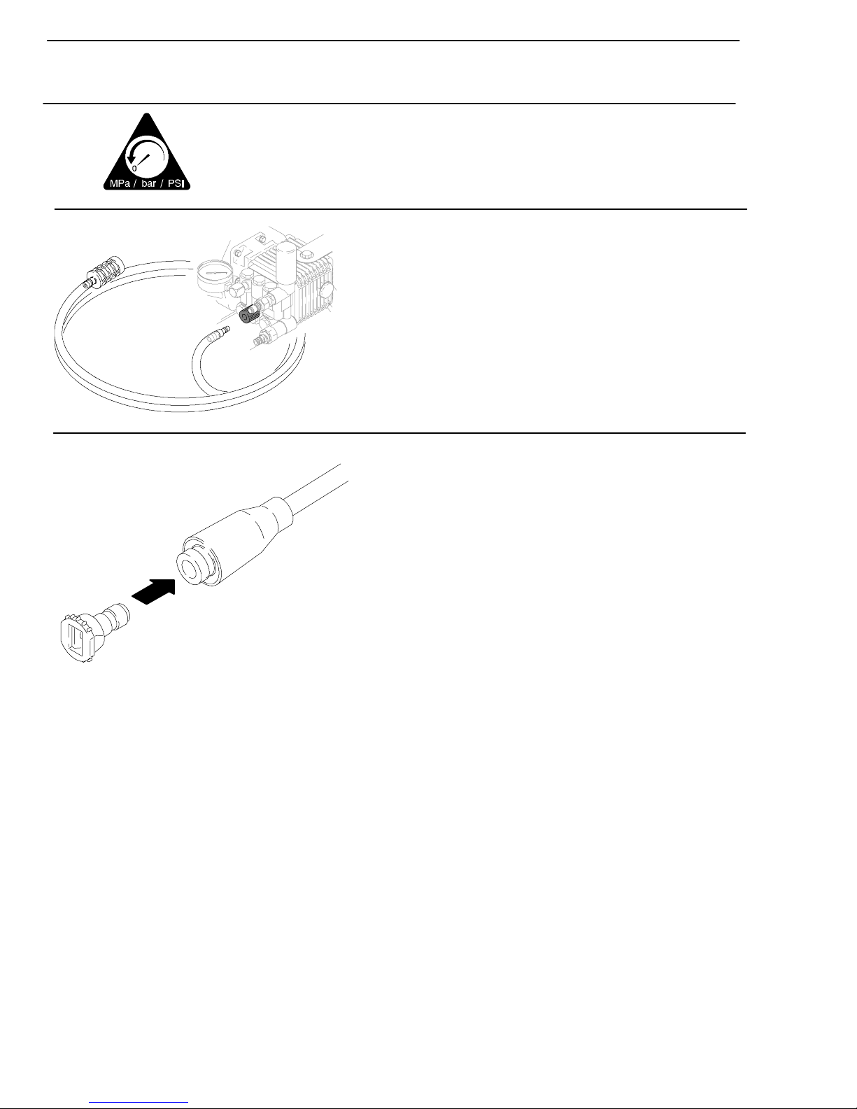
Connect High--Pressure Hose and Gun
Connect the high--pressure hose between the pump outlet and gun inlet.
Both of these connections are made with quick couplers.
CAUTION
Up to 100 ft (30 m) of 3/8” high--pressure hose may be used. Longer hoses could affect pressure
washer and chemical injector performance balance.
Install Spray Tip
Install the spray tip on the wand. (Installing and Changing Spray Tips, page 13). If you are using a Sandblasting Kit, see its separate manual for installation instructions.
Connect to Water Supply
Connect hose with at least a 3/4--in (19 mm) ID from the water supply to the 3/4--in garden hose inlet
on the pressure washer. The supply hose should not be more than 50 ft (15 m) long.
5309368
Page 6

CAUTION
Before you connect the garden hose to the pressure washer, check your local plumbing code regarding
cross--connection to the water supply. If required, install a backflow preventer.
If the inlet water pressure is over 60 psi (4.1 bar), a regulating water valve must be installed at the garden
hose connection.
Do not exceed 160_F(70_C) inlet water temperature.
NOTE: The water source must have a minimum flow rate equal to that of the pressure washer.
6 309368
Page 7

PRESSURE RELIEF
Follow these instructions whenever you are instructed to relieve pressure, stop spraying for more than 10 minutes, check or service the
equipment, or install or clean the spray nozzle.
1. Engage trigger safety latch.
2. Turn pressure washer off.
3. Remove ignition cable from spark plug.
4. Shut off water supply. Disconnect from water.
5. Disengage trigger safety latch and trigger the gun to
relieve pressure. Then re--engage the safety latch.
Note: If you suspect that the spray tip or hose is clogged or that pressure has not been fully relieved after
following the steps above, disengage the trigger safety latch and trigger the gun to relieve pressure.
7309368
Page 8

Operation
Startup
Always use this startup procedure to ensure that the pressure washer is started safely and properly.
D Always engage the gun trigger safety latch when you stop spraying. This reduces the risk of fluid
injection or splashing in the eyes or on the skin if the gun is bumped or triggered accidentally.
D Always observe the CAUTIONS in this section to avoid costly damage to the pressure washer.
D If you use the Sandblaster Kit, see the Sandblaster Kit Manual for detailed cleaning information.
.
. Check the oil level of the engine and pump.
1
Oil level
NOTE: All Honda engine powered pressure washers are equipped with an engine low-oil sensor that shuts the
engine off if the oil level falls below a certain level. If the engine stops unexpectedly, check the oil and the fuel
levels. Check the oil level each time you add fuel.
WARNING
FIRE HAZARD
Do not refuel a hot engine. Refueling a hot engine could cause a fire. Use only fresh, clean,
regular or unleaded gasoline. Close the fuel shutoff valve during refueling.
2. Check fuel level.
3. Check oil level in pump. It should be half way up the sight
glass located on the front of the pump. Add pump oil as
necessary . The system is equipped with a thermal overload to help prevent severe damage.
Fuel level
Oil level
NOTE: It is important to drain and refill the pump oil after the first 50 hours of operation.
8 309368
Page 9

4
. Turn on water supply.
CAUTION
Never run pressure washer without water. Costly damage to the pump will result. Always be sure the water
supply is completely turned on before you run the pressure washer.
5
. Trigger the gun until a constant stream of water sprays from the tip indicating
the air is purged from the system.
6. Open fuel shutoff valve. Be sure the spark plug ignition
cable is pushed firmly onto the spark plug.
7. Put the switch in the ON position and the throttle at HALF
throttle.
9309368
Page 10
CAUTION
Do not allow pressure washer to idle for more than 10 minutes. This causes the recirculating water to
overheat and serious damage to pump. Turn off pressure washer if it will not be spraying at least every 10
minutes. If heated inlet water is used, reduce this time more. Do not operate pressure washer with inlet
water screen removed. This screen helps keep abrasive sediment out of pump, which could clog pump or
damage cylinders. Keep screen clean. Do not pump caustic materials; such materials could corrode pump
components.
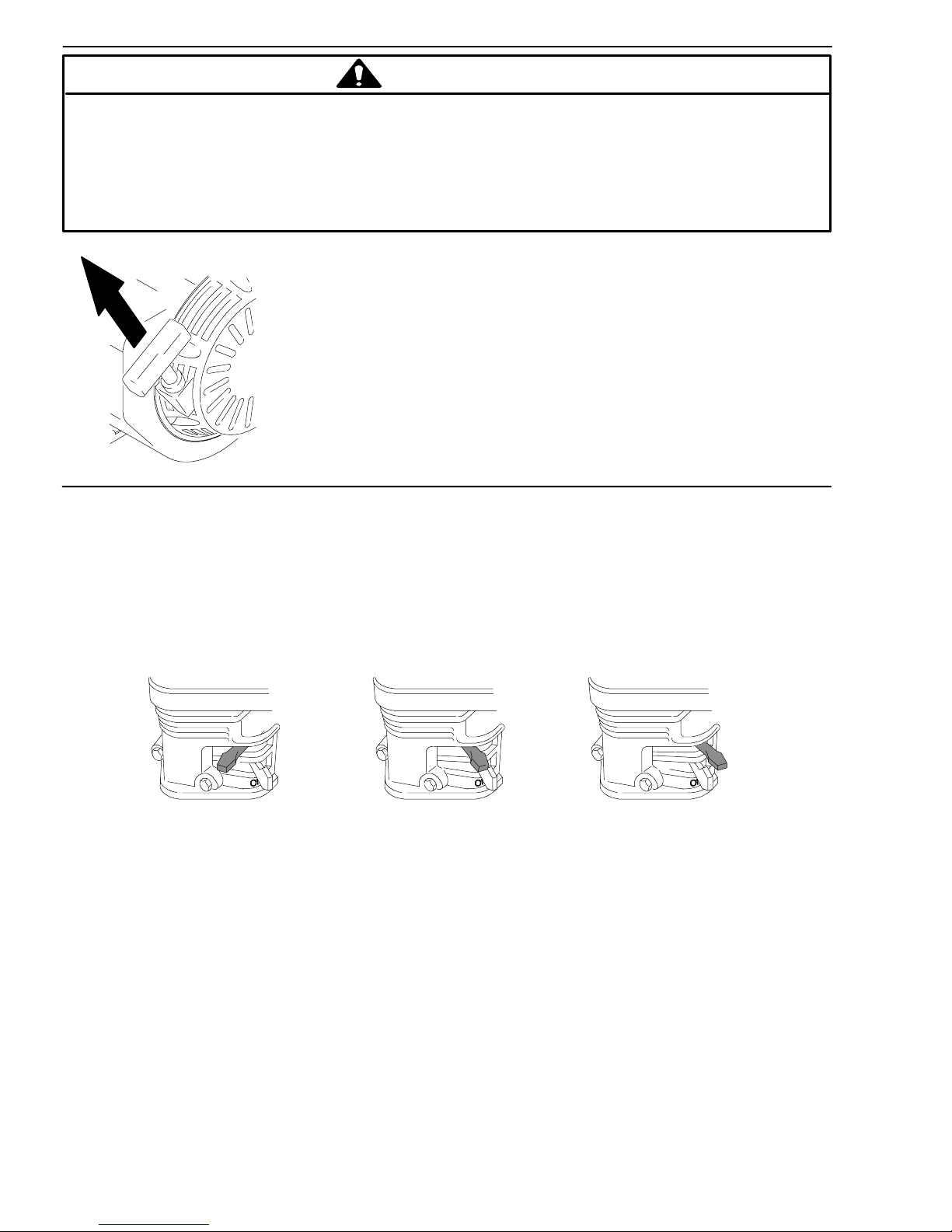
8. Pull the starter rope quickly to start the engine.
Pull and return the rope until the engine starts.
HINT: Placing one foot on the pressure washer
as a brace provides better leverage.
NOTE: For easier starting, have one person start pressure washer while another triggers gun.
D If engine is cold, start engine with choke completely closed. In cool weather, you might have to let engine
run with choke closed for first 10--30 seconds. In warm weather, open choke completely as soon as engine starts.
D If engine is warm, start engine with choke completely open or partially closed. When engine starts open
choke completely.
CLOSED
HALF
OPEN
10 309368
Page 11
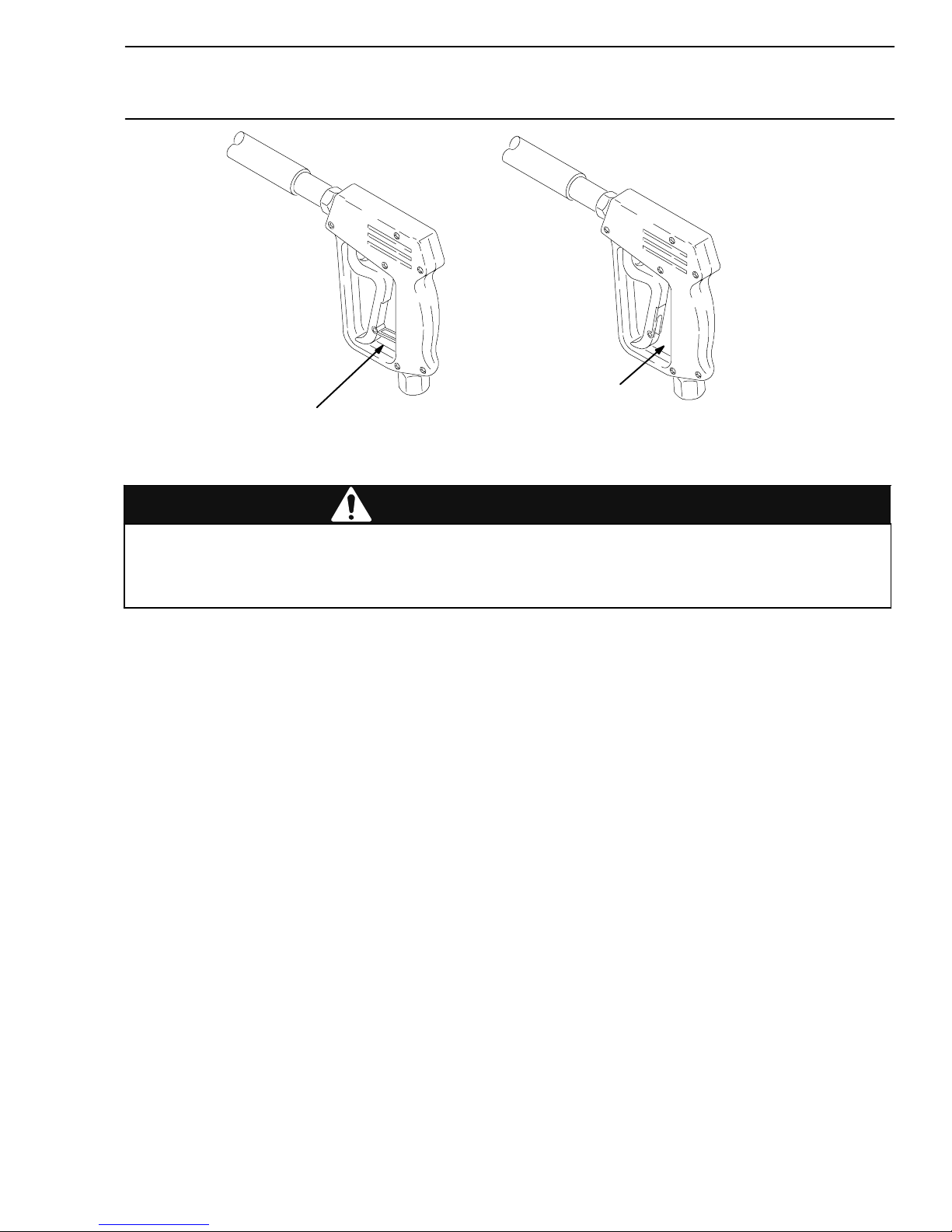
Trigger Safety Latch
Always engage the safety latch when you stop spraying.
disengaged
engaged
WARNING
Always engage the trigger safety latch when you stop spraying even for a moment. The
engaged, safety latch prevents the fun from being triggered accidentally by hand or when
dropped or bumped. Be sure the latch is pushed fully down, or it will not prevent the gun from
being triggered.
WARNING
11309368
Page 12
Chemical Injector Operation
1
. Follow Pressure Relief Procedure (page 7).
2. Insert chemical filter (attached with clear tubing to
chemical injector) into the container of chemical.
Insert brass coupler into chemical injector.
3. Install the black, large--orifice, chemical tip. (Instal-
ling and Changing Spray Tips page 13).
The large orifice of the chemical tip causes a drop in
pressure that actuates the chemical injector. Changing
back to a small orifice spray tip deactivates the chemical injector and produces high pressure for rinsing.
The chemical filter can be left in the chemical container
during high--pressure use. To regulate the flow rate of
the chemical, turn the chemical adjustment knob on the
injector.
12 309368
Page 13

Installing and Changing Spray Tips
Spray tips have 4-- or 5--digit numbers on them.
The first two digits are the spray angle. Tip
holding holes are provided on the chassis.
NOTE: The chemical injector tip is brass and has a large opening and a black plastic cap.
. Perform Pressure Relief Procedure (page 7).
1
2. Point the gun and wand away from you and anyone else.
Spray Tip
Number
00XXX
15XXX
25XXX
40XXX
Chemical
Spray Pattern Fan Angle
0_ blaster (red)
15_ (yellow)
25_ (green)
40_ (white)
XX_ (black)
3. Without holding your hand over the spray tip (A), pull back the
quick coupler ring (B). Remove the current tip, install a different one. Then push the ring back on.
A
B
CAUTION
To avoid blowing the O-ring out of the quick coupler due to the high pressure in the system, never operate
the pressure washer without a tip securely mounted in the quick coupler.
13309368
Page 14

Shutdown, Flushing, and Storage
D Before you store the pressure washer
overnight or transport it, disconnect the water
supply, and turn off the fuel supply valve.
D After each use, wipe all surfaces of the
pressure washer with a clean, damp cloth.
14 309368
Page 15

Long T erm (more than 30 days)/Winter Storage
S Do not store unit outside where it can be exposed to rain, dirt or adverse weather condi-
tions.
S Do not expose pressure washer to freezing temperatures or allow water to freeze in
pressure washer components, causing the pump to lock--up. If this happens let pump
thaw naturally in WARM ENVIRONMENT. DO NOT attempt to to speed up this process
by pouring warm water on pump. This could cause further damage.
ENGINE:
1. Run engine until gas is gone or stabilize the fuel and run it through the fuel system and carburetor.
2. Drain water out of pressure washer hose.
3. Turn fuel system to OFF position.
Pump:
1. Attach one end of a 4 or 5--foot section of hose to pump inlet and other end in an antifreeze
solution approximately 1--foot off the ground.
2. Pull pull--cord on engine until antifreeze comes out of pump outlet.
Storage Location:
1. Store pressure washer in garage, basement or other area where it is protected from freezing
temperatures.
15309368
Page 16

Parts for 2730 Pressure Washer
Model 244811, Series A
40
14
4
5
8--12
1
45
29*
41
42
44
31
43
18
27
34*
39
2
33*
35*
30
32*
28
23
25
3
20
21
22
16
ti1309B
17
19
7
26
38, 15
16 309368
Page 17

Parts for 2730 Pressure Washer
Model 244811, Series A with 6.5 HP Briggs & Stratton motor
Ref.
Ref.
Part
No.
No.
1 1 16299 1
2 244749 1
3 244767 1
4 244779 1
5 244782 1
7 80451 1 2
8 805535 1
9 805536 1
10 805537 1
1 1 805538 1
244768 1
12 805634 1
14 804275 1
15 1 16342 2
16 1 10837 4
17 1 11040 4
18 197428 1
19 1 16411 2
20 801546 2
Description Qty.
Part
No.
No.
21 100132 2
22 101566 2
23 801504 2
25 197792 1
26 1 16477 2
27 244803 1
28 1 16460 1
29 244741 1
30 1 16557 1
31 1 16558 1
32 804037 1
33 804402 1
34 80401 1 1
35 804033 1
38 1 16563 2
39 244821 1
40 198012 1
41 804582 1
42 15B910 1
43 244746 1
44 801 112 1
45 287643 1
Description Qty.
17309368
Page 18

Parts for 2730 Pressure Washer
Model 244812, Series A, with Honda 6.5 HP Motor
4
40
41
*34
*33
2
31
39
18
42
29*
45
44
* internal replacement parts
27
43
30
*35
*32
5
25
1
16
19
26
22
20
17
7
38, 15
14
28
3
23
21
8--12
18 309368
Page 19

Parts for 2730 Pressure Washer
Model 244812, Series A with Honda 6.5 HP Motor
Ref.
No.
1 1 16298 1
2 244749 1
3 244767 1
4 244779 1
5 244782 1
7 80451 1 2
8 805535 1
9 805536 1
10 805537 1
1 1 805538 1
12 805634 1
14 804275 1
15 116342 2
16 110837 4
17 111040 4
18 197428 1
19 116411 2
20 801546 2
Part No. Description Qty.
244768 1
Ref.
No.
21 100132 2
22 101566 2
23 801504 2
25 197792 1
26 116477 2
27 244803 1
28 116460 1
29 244741 1
30 116557 1
31 116558 1
32 804037 1
33 804402 1
34 804011 1
35 804033 1
38 116563 2
39 244821 1
40 198012 1
41 804582 1
42 15B910 1
43 244746 1
44 801112 1
45 287643 1
Part No. Description Qty.
19309368
Page 20

Parts for 3030/3340/3540 Pressure Washer
Model 244813, Series A with Honda 9 HP Motor†
Model 244814, Series A, with Honda 11 HP Motor
Model 244815, Series A, with Honda 13 HP Motor
4
41
3
42
31
40
18
43
29*
46
45
44
* internal replacement parts
*33
27
*34
2
30
*35
*32
28
14
5
8--12
1
25
16
19
26
23
21
20
22
17
38
39, 15
7
20 309368
Page 21

Parts for 3030/3340/3540 Pressure Washer
Model 244813, Series A with Honda 9 HP Motor†
Model 244814, Series A with Honda 11 HP MotorG
Model 244815, Series A with Honda 13 HP Motorn
Ref.
No.
1
2
3 244767 1
4 244779 1
5
7
8
9
10
11
12 805634 1
14 804275 1
15 1 16342 2
16 1 10837 4
17 1 11040 4
Part No. Description Qty.
803900
803158G 1
1 14703n 1
244750
244751G 1
244752n 1
244782
244783Gn 1
80451 1
1 16478Gn 2
805539
805543
805540
805544
805541
805545
805542
805546
244769
800708
†
†
†
†
†G
n 1
†G
n 1
†G
n 1
†G
n 1
†G
n 1
Ref.
No.
1
1
1
2
1
1
1
1
1
18 197428 1
19 116411 2
20 801546 2
21 100132 2
22 101566 2
23 801504 2
25 801137 1
26 116477 2
27 244804 1
28 116461 1
29 244741 1
30 116559 1
31 116558 1
32 804404 1
33 804402 1
34 804415 1
35 804033 1
38 198055 2
39 116563 2
40 244821 1
41 198012 1
42 804582 1
43 15B910 1
44 244746 1
45 801112 1
46 287643 1
Part No. Description Qty.
244805 1
244806 1
21309368
Page 22

Notes
22 309368
Page 23

Sound Data
Direct Drive Pressure Washer Models
Sound Data
Sound Pressure 92.5 dB(A) 89.0 dB(A) 93.3 dB(A) 90.4 dB(A) 90.7 dB(A)
Sound Level 106.8 dB(A) 103.3 dB(A) 107.6 dB(A) 104.7 dB(A) 105.0 dB(A)
2730
Briggs &
Stratton
Motor
2730
Honda Motor
3030 3340 3540
23309368
Page 24

Graco Standard Warranty
Graco warrants allequipment manufactured byGraco andbearing its nameto be free fromdefects in material andworkmanship onthe
date of sale by an authorized Gracodistributor tothe original purchaser foruse. With the exception ofany special,extended, orlimited
warrantypublished byGraco, Graco will, for a period oftwelve months from the dateof sale,repair or replace any part of the equipment
determined by Graco to be defective. This warranty applies only when the equipment is installed,operated and maintained in accordance with Graco’s written recommendations.
This warranty does not cover, and Gracoshall not be liable for general wear and tear, or any malfunction,damage or wear caused by
faultyinstallation, misapplication,abrasion, corrosion, inadequate orimproper maintenance, negligence, accident, tampering, orsubstitution of non--Graco component parts. Nor shall Graco be liable for malfunction, damage or wear caused by the incompatibility of
Graco equipment with structures, accessories, equipment or materials not supplied by Graco, or the improper design, manufacture,
installation, operation or maintenance of structures, accessories, equipment or materials not supplied by Graco.
This warranty is conditioned upon the prepaid return of the equipment claimed to be defective to an authorized Graco distributor for
verification of the claimed defect. If the claimed defect is verified, Graco will repair or replace free of charge any defective parts. The
equipmentwill bereturned to theoriginal purchaser transportationprepaid. If inspection ofthe equipmentdoes notdisclose any defect
in material or workmanship, repairs will be made at a reasonable charge, which charges may include the costs of parts, labor, and
transportation.
THIS WARRANTY IS EXCLUSIVE, AND IS IN LIEU OF ANY OTHER WARRANTIES, EXPRESS OR IMPLIED, INCLUDING BUT
NOT LIMITED TO WARRANTY OF MERCHANTABILITY OR WARRANTY OF FITNESS FOR A PARTICULAR PURPOSE.
Graco’ssole obligationand buyer’ssole remedyfor anybreach ofwarrantyshall be as set forth above. The buyer agrees thatno other
remedy (including, but not limited to, incidental or consequential damages for lost profits, lost sales, injury to person or property,or any
other incidental or consequential loss) shall be available. Any actionfor breachof warrantymust be brought withintwo (2) years of the
date of sale.
Graco makes no warranty, and disclaims all implied warranties of merchantability and fitness for a particular purpose in connection
with accessories, equipment, materials or components sold but not manufactured by Graco. These items sold, but not manufactured
by Graco (such as electric motors, switches, hose, etc.), are subject to the warranty, if any, of their manufacturer. Graco will provide
purchaser with reasonable assistance in making any claim for breach of these warranties.
In no event will Graco be liable for indirect, incidental, special or consequential damages resulting from Graco supplying equipment
hereunder, or the furnishing, performance, or use of any products or other goods sold hereto, whether due to a breach of contract,
breach of warranty, the negligence of Graco, or otherwise.
FOR GRACO CANADA CUST
The parties acknowledge that they have required that the present document, as well as all documents, notices and legal proceedings
entered into, given orinstituted pursuant hereto or relating directly or indirectly hereto, be drawn up in English. Les parties reconnaissent avoirconvenu que la rédaction du présente document sera en Anglais, ainsique tous documents, aviset procédures judiciaires
exécutés, donnés ou intentés à la suite de ou en rapport, directement ou indirectement, avec les procedures concernées.
OMERS
TO PLACE AN ORDER OR FOR SERVICE, contact your Graco distributor, or call this number to identify the
distributor near you:1--800--690--2894 Toll Free
mm 309368
All written and visual data contained in this document reflects the latest product information available at the time of publication.
Graco reserves the right to make changes at any time without notice.
International Offices: Belgium, China, Japan, Korea
GRACO INC. P.O. BOX 1441 MINNEAPOLIS, MN 55440 --1441
24 309368
Graco Headquarters: Minneapolis
www.graco.com
Printed in USA 309368F
8/2001 Rev. 07/2008
 Loading...