

Page 1

Instructions-Parts
ProDispense™
Used to meter and dispense paints, coatings, solvents, water, and lubrication fluids.
For Professional Use Only.
Not for use in explosive atmospheres.
309301G
Part No. 244561 Electronic Preset Dispense System
Important Safety Instructions
Read all warnings and instructions in this manual.
Save these instructions.
See page 4 for maximum working fluid pressure
and system component information.
ENG
Conforms to ANSI/UL
standard 3121-1
CAN/CSA C22.2 No 1010-1-92
Page 2

Contents
ProDispense System Components. . . . . . . . . . . . . . . . . . . . . . . . . . . . . . . . . . . . . . . . . . . . . . 4
Conventions . . . . . . . . . . . . . . . . . . . . . . . . . . . . . . . . . . . . . . . . . . . . . . . . . . . . . . . . . . . . . . . . 5
WARNING . . . . . . . . . . . . . . . . . . . . . . . . . . . . . . . . . . . . . . . . . . . . . . . . . . . . . . . . . . . . . . . . . . 6
Overview . . . . . . . . . . . . . . . . . . . . . . . . . . . . . . . . . . . . . . . . . . . . . . . . . . . . . . . . . . . . . . . . . . . 8
How the ProDispense System Works . . . . . . . . . . . . . . . . . . . . . . . . . . . . . . . . . . . . . . . . . . . . . . . . . . . . . . . . . . 8
Main Components . . . . . . . . . . . . . . . . . . . . . . . . . . . . . . . . . . . . . . . . . . . . . . . . . . . . . . . . . . . . . . . . . . . . . . . . . 9
Installation . . . . . . . . . . . . . . . . . . . . . . . . . . . . . . . . . . . . . . . . . . . . . . . . . . . . . . . . . . . . . . . . 14
Install the Fluid Supplies . . . . . . . . . . . . . . . . . . . . . . . . . . . . . . . . . . . . . . . . . . . . . . . . . . . . . . . . . . . . . . . . . . . 15
Mount the Fluid Panel(s) . . . . . . . . . . . . . . . . . . . . . . . . . . . . . . . . . . . . . . . . . . . . . . . . . . . . . . . . . . . . . . . . . . . 16
Connect the Air and Fluid Lines . . . . . . . . . . . . . . . . . . . . . . . . . . . . . . . . . . . . . . . . . . . . . . . . . . . . . . . . . . . . . 16
Install the Remote Operator Station . . . . . . . . . . . . . . . . . . . . . . . . . . . . . . . . . . . . . . . . . . . . . . . . . . . . . . . . . . 17
Mount the Controller . . . . . . . . . . . . . . . . . . . . . . . . . . . . . . . . . . . . . . . . . . . . . . . . . . . . . . . . . . . . . . . . . . . . . . 18
Connect the Cables and Power Cord . . . . . . . . . . . . . . . . . . . . . . . . . . . . . . . . . . . . . . . . . . . . . . . . . . . . . . . . . 19
Ground the System . . . . . . . . . . . . . . . . . . . . . . . . . . . . . . . . . . . . . . . . . . . . . . . . . . . . . . . . . . . . . . . . . . . . . . . 20
Check the Resistance . . . . . . . . . . . . . . . . . . . . . . . . . . . . . . . . . . . . . . . . . . . . . . . . . . . . . . . . . . . . . . . . . . . . . 20
Connect a Printer (optional) . . . . . . . . . . . . . . . . . . . . . . . . . . . . . . . . . . . . . . . . . . . . . . . . . . . . . . . . . . . . . . . . 21
Connect to a PC or Alarm (optional) . . . . . . . . . . . . . . . . . . . . . . . . . . . . . . . . . . . . . . . . . . . . . . . . . . . . . . . . . . 21
Before Beginning Operation . . . . . . . . . . . . . . . . . . . . . . . . . . . . . . . . . . . . . . . . . . . . . . . . . . . . . . . . . . . . . . . . 22
Startup. . . . . . . . . . . . . . . . . . . . . . . . . . . . . . . . . . . . . . . . . . . . . . . . . . . . . . . . . . . . . . . . . . . . 23
Pressure Relief Procedure . . . . . . . . . . . . . . . . . . . . . . . . . . . . . . . . . . . . . . . . . . . . . . . . . . . 24
Shutdown . . . . . . . . . . . . . . . . . . . . . . . . . . . . . . . . . . . . . . . . . . . . . . . . . . . . . . . . . . . . . . . . . 24
Setup Mode. . . . . . . . . . . . . . . . . . . . . . . . . . . . . . . . . . . . . . . . . . . . . . . . . . . . . . . . . . . . . . . . 25
Screen Navigation . . . . . . . . . . . . . . . . . . . . . . . . . . . . . . . . . . . . . . . . . . . . . . . . . . . . . . . . . . . . . . . . . . . . . . . .25
System Setup Screen . . . . . . . . . . . . . . . . . . . . . . . . . . . . . . . . . . . . . . . . . . . . . . . . . . . . . . . . . . . . . . . . . . . . . 26
Fluid Setup Screen . . . . . . . . . . . . . . . . . . . . . . . . . . . . . . . . . . . . . . . . . . . . . . . . . . . . . . . . . . . . . . . . . . . . . . . 27
Recipe Setup Screen. . . . . . . . . . . . . . . . . . . . . . . . . . . . . . . . . . . . . . . . . . . . . . . . . . . . . . . . . . . . . . . . . . . . . . 28
Calibrate Meter Screen . . . . . . . . . . . . . . . . . . . . . . . . . . . . . . . . . . . . . . . . . . . . . . . . . . . . . . . . . . . . . . . . . . . . 28
Dispense Mode. . . . . . . . . . . . . . . . . . . . . . . . . . . . . . . . . . . . . . . . . . . . . . . . . . . . . . . . . . . . . 29
Screen Navigation . . . . . . . . . . . . . . . . . . . . . . . . . . . . . . . . . . . . . . . . . . . . . . . . . . . . . . . . . . . . . . . . . . . . . . . .29
Run Screen . . . . . . . . . . . . . . . . . . . . . . . . . . . . . . . . . . . . . . . . . . . . . . . . . . . . . . . . . . . . . . . . . . . . . . . . . . . . . 30
Fluid Totals Screen . . . . . . . . . . . . . . . . . . . . . . . . . . . . . . . . . . . . . . . . . . . . . . . . . . . . . . . . . . . . . . . . . . . . . . . 32
Alarm History Screen . . . . . . . . . . . . . . . . . . . . . . . . . . . . . . . . . . . . . . . . . . . . . . . . . . . . . . . . . . . . . . . . . . . . . 33
Operation Procedures . . . . . . . . . . . . . . . . . . . . . . . . . . . . . . . . . . . . . . . . . . . . . . . . . . . . . . . 34
Loading Fluid Lines . . . . . . . . . . . . . . . . . . . . . . . . . . . . . . . . . . . . . . . . . . . . . . . . . . . . . . . . . . . . . . . . . . . . . . . 34
Manual Dispense. . . . . . . . . . . . . . . . . . . . . . . . . . . . . . . . . . . . . . . . . . . . . . . . . . . . . . . . . . . . . . . . . . . . . . . . . 34
Automatic Dispense. . . . . . . . . . . . . . . . . . . . . . . . . . . . . . . . . . . . . . . . . . . . . . . . . . . . . . . . . . . . . . . . . . . . . . . 34
Purging Fluid . . . . . . . . . . . . . . . . . . . . . . . . . . . . . . . . . . . . . . . . . . . . . . . . . . . . . . . . . . . . . . . . . . . . . . . . . . . . 35
Emergency Stop . . . . . . . . . . . . . . . . . . . . . . . . . . . . . . . . . . . . . . . . . . . . . . . . . . . . . . . . . . . . . . . . . . . . . . . . . 35
Troubleshooting . . . . . . . . . . . . . . . . . . . . . . . . . . . . . . . . . . . . . . . . . . . . . . . . . . . . . . . . . . . . 36
Service . . . . . . . . . . . . . . . . . . . . . . . . . . . . . . . . . . . . . . . . . . . . . . . . . . . . . . . . . . . . . . . . . . . 37
Removing and Installing Controller . . . . . . . . . . . . . . . . . . . . . . . . . . . . . . . . . . . . . . . . . . . . . . . . . . . . . . . . . . . 37
2 309301G
Page 3

Replacing Display Board . . . . . . . . . . . . . . . . . . . . . . . . . . . . . . . . . . . . . . . . . . . . . . . . . . . . . . . . . . . . . . . . . . 39
Replacing Display. . . . . . . . . . . . . . . . . . . . . . . . . . . . . . . . . . . . . . . . . . . . . . . . . . . . . . . . . . . . . . . . . . . . . . . . 40
Replacing Membrane . . . . . . . . . . . . . . . . . . . . . . . . . . . . . . . . . . . . . . . . . . . . . . . . . . . . . . . . . . . . . . . . . . . . . 40
Replacing Main Board . . . . . . . . . . . . . . . . . . . . . . . . . . . . . . . . . . . . . . . . . . . . . . . . . . . . . . . . . . . . . . . . . . . . 41
Replacing Power Supply. . . . . . . . . . . . . . . . . . . . . . . . . . . . . . . . . . . . . . . . . . . . . . . . . . . . . . . . . . . . . . . . . . . 42
Replacing Fluid Panel Junction Box . . . . . . . . . . . . . . . . . . . . . . . . . . . . . . . . . . . . . . . . . . . . . . . . . . . . . . . . . . 43
Servicing Fluid Panel 244599. . . . . . . . . . . . . . . . . . . . . . . . . . . . . . . . . . . . . . . . . . . . . . . . . . . . . . . . . . . . . . . 46
Servicing Fluid Panel 244600. . . . . . . . . . . . . . . . . . . . . . . . . . . . . . . . . . . . . . . . . . . . . . . . . . . . . . . . . . . . . . . 48
Servicing Fluid Panel 244601 and 246837. . . . . . . . . . . . . . . . . . . . . . . . . . . . . . . . . . . . . . . . . . . . . . . . . . . . . 50
Servicing Fluid Panel 246838. . . . . . . . . . . . . . . . . . . . . . . . . . . . . . . . . . . . . . . . . . . . . . . . . . . . . . . . . . . . . . . 52
Servicing Fluid Panel 246839. . . . . . . . . . . . . . . . . . . . . . . . . . . . . . . . . . . . . . . . . . . . . . . . . . . . . . . . . . . . . . . 54
Wiring Charts . . . . . . . . . . . . . . . . . . . . . . . . . . . . . . . . . . . . . . . . . . . . . . . . . . . . . . . . . . . . . . . . . . . . . . . . . . . 56
Parts. . . . . . . . . . . . . . . . . . . . . . . . . . . . . . . . . . . . . . . . . . . . . . . . . . . . . . . . . . . . . . . . . . . . . . 62
Part No. 244561, Controller . . . . . . . . . . . . . . . . . . . . . . . . . . . . . . . . . . . . . . . . . . . . . . . . . . . . . . . . . . . . . . . . 62
Part No. 244599, Fluid Panel . . . . . . . . . . . . . . . . . . . . . . . . . . . . . . . . . . . . . . . . . . . . . . . . . . . . . . . . . . . . . . . 64
Part No. 244600, Fluid Panel . . . . . . . . . . . . . . . . . . . . . . . . . . . . . . . . . . . . . . . . . . . . . . . . . . . . . . . . . . . . . . . 65
Part No. 244601, Fluid Panel . . . . . . . . . . . . . . . . . . . . . . . . . . . . . . . . . . . . . . . . . . . . . . . . . . . . . . . . . . . . . . . 66
Part No. 246837, Fluid Panel . . . . . . . . . . . . . . . . . . . . . . . . . . . . . . . . . . . . . . . . . . . . . . . . . . . . . . . . . . . . . . . 67
Part No. 246838, Fluid Panel . . . . . . . . . . . . . . . . . . . . . . . . . . . . . . . . . . . . . . . . . . . . . . . . . . . . . . . . . . . . . . . 68
Part No. 246839, Fluid Panel . . . . . . . . . . . . . . . . . . . . . . . . . . . . . . . . . . . . . . . . . . . . . . . . . . . . . . . . . . . . . . . 69
Notes . . . . . . . . . . . . . . . . . . . . . . . . . . . . . . . . . . . . . . . . . . . . . . . . . . . . . . . . . . . . . . . . . . . . . 70
Technical Data. . . . . . . . . . . . . . . . . . . . . . . . . . . . . . . . . . . . . . . . . . . . . . . . . . . . . . . . . . . . . . 71
Accessories and Kits . . . . . . . . . . . . . . . . . . . . . . . . . . . . . . . . . . . . . . . . . . . . . . . . . . . . . . . . 73
Graco Standard Warranty . . . . . . . . . . . . . . . . . . . . . . . . . . . . . . . . . . . . . . . . . . . . . . . . . . . . 74
Graco Information. . . . . . . . . . . . . . . . . . . . . . . . . . . . . . . . . . . . . . . . . . . . . . . . . . . . . . . . . . . 74
309301G 3
Page 4

ProDispense System Components
ProDispense System Components
Follow the instructions in this manual (309301) and refer to the component manuals for additional warning, operation, service, and parts information. See the table below for:
• maximum working pressure of the fluid panels
• component part numbers and manual numbers
• parts list page numbers
Fluid Panels Part No. 244599
Oil/Lubricant
Maximum Working Pressure 1500 psi (10 MPa, 103 bar) 250 psi (1.7 MPa, 17 bar) 3000 psi (21 MPa, 207 bar)
Fluid Meter Part No. 238618 513891 239716
Manual No. 308245 — 308778
Dispense Valve Part No. — — 205612
Manual No. — — 306715
Parts List Page No. 64 65 66
Fluid Panels Part No. 246837
Grease/Paint
Maximum Working Pressure 3000 psi (21 MPa, 207 bar) 3000 psi (21 MPa, 207 bar) 3000 psi (21 MPa, 207 bar)
Fluid Meter Part No. 244292 — 246190
Manual No. 308778 — 309834
Dispense Valve Part No. 205612 205612 205612
Manual No. 306715 306715 306715
Parts List Page No. 69 70 71
ProDispense Controller Part No. 244561
Parts List Page No. 62
244600
Water/Antifreeze
246838
Meterless
244601
Grease/Paint
246839
Sealants
Remote Operator Station Part No. 116669
4 309301G
Page 5
Conventions
The following conventions are used in this manual to help guide you through the information.
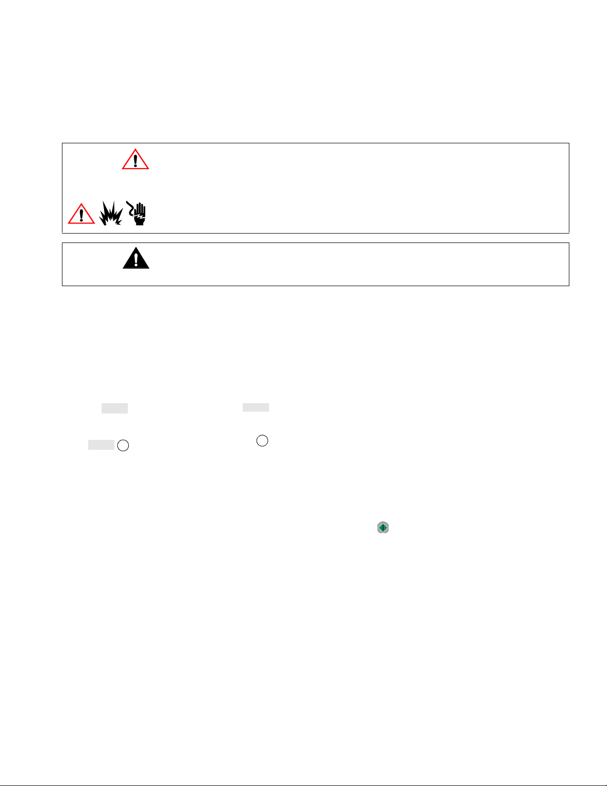
Warning Symbols
The warning symbol alerts you to the possibility of serious injury or death if you do not follow
the instructions.
Symbols, such as fire, explosion, or electric shock hazard (shown at left), alert you to the specific hazard. Read the main Warnings on pages 6-7 for detailed information about the hazard
indicated.
Caution Symbol
The caution symbol alerts you to the possibility of equipment or property damage or to operation errors if you do not follow the instructions.
Note Symbol
The note symbol is used to call your attention to additional helpful information.
Conventions
Amount 20 qts
Recipe#
ID#
1. Enter the ID
number.
• Italicized text in a screen diagram indicates the text may vary according to how the sys-
tem parameters have been configured. For example, the units of measure shown in the
manual may be qts (quarts). The units you see on your screen may be pounds, kilograms,
quarts, gallons, or liters.
• A shaded box is used to indicate a value/field that can be edited on the controller
screen.
1
• A circled number in a screen diagram relates a field on the screen to a step in a proce-
dure.
1
• Numbers and letters in parentheses in the text, such as (A) or (7), refer to reference num-
bers and letters in the figures.
• When you need to press a key during a procedure, the key is indicated by an icon as
shown in the following example: Press Start to begin the dispense.
309301G 5
Page 6
WARNING
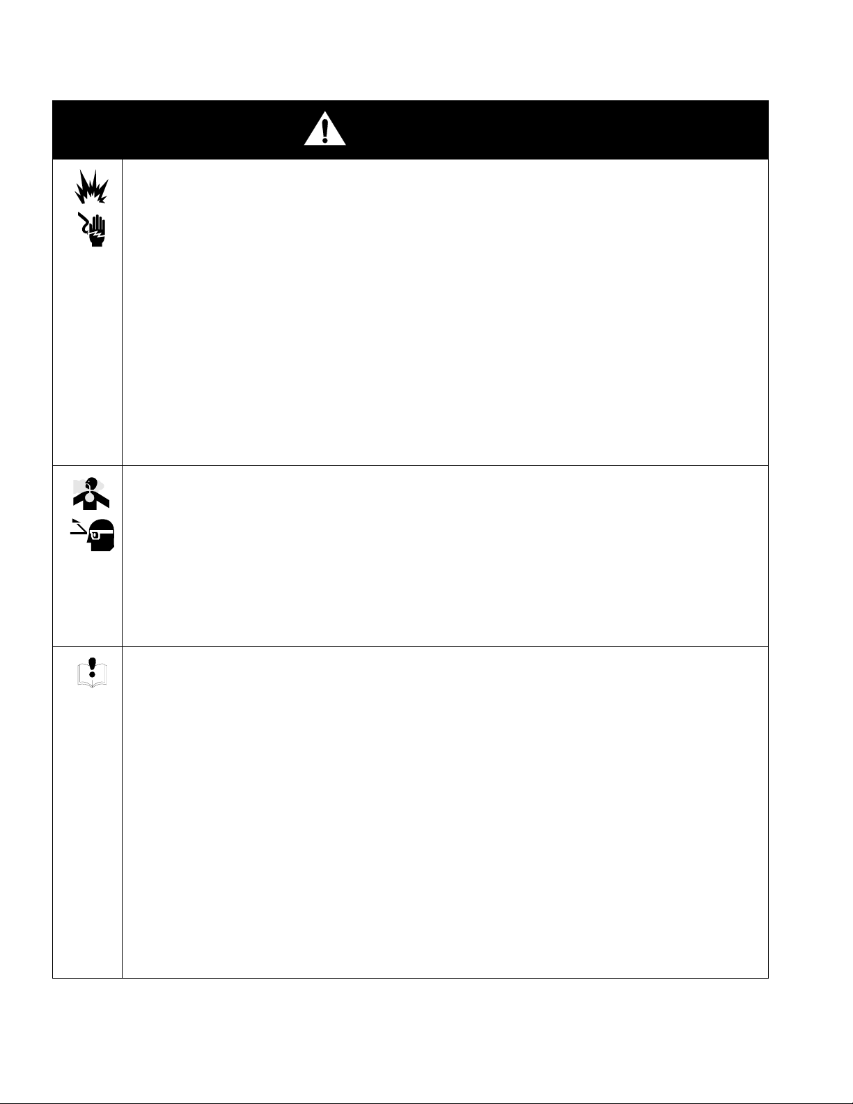
WARNING
FIRE, EXPLOSION, AND ELECTRIC SHOCK HAZARD
Improper grounding, poor ventilation, open flames or sparks can cause a hazardous condition and result
in fire, explosion or electric shock.
• Installation and service of electrical components must be completed by a qualified electrician.
• Do not install the ProDispense controller, fluid panels, or remote operator station in a hazardous
location.
• Ground the equipment. See Ground the System, page 20.
• If there is any static sparking while using equipment, stop dispensing immediately. Identify and
correct the problem.
• Provide fresh air ventilation to avoid buildup of flammable fumes.
• Eliminate all ignition sources, such as cigarettes.
• Avoid spilling fluids onto electrical components.
• Turn off the ProDispense controller power switch before servicing equipment.
TOXIC FLUID HAZARD
Hazardous fluid or toxic fumes can cause serious injury or death if splashed in the eyes or on the skin,
inhaled, or swallowed.
• Always wear protective eyewear, gloves, clothing and respirator as recommended by the fluid and
solvent manufacturer.
• Know the specific hazards of the fluid you are using.
• Store hazardous fluid in an approved container. Dispose of hazardous fluid according to all local,
state and national guidelines.
EQUIPMENT MISUSE HAZARD
Equipment misuse can cause the equipment to rupture or malfunction and result in serious injury.
• This equipment is for professional use only.
• Read all instruction manuals, tags, and labels before operating the equipment.
• Use the equipment only for its intended purpose. If you are not sure, call your Graco distributor.
• Do not alter or modify this equipment.
• Check equipment daily. Repair or replace worn or damaged parts immediately.
• Do not exceed the maximum working pressure stated on the equipment or in the Technical Data,
page 71.
• Use fluids and solvents which are compatible with the equipment wetted parts. Refer to the Techni-
cal Data in all equipment manuals and the fluid manufacturer warnings.
• Route hoses away from traffic areas, sharp edges, moving parts, and hot surfaces. Do not expose
Graco hoses to temperatures above 180° F (82° C) or below -40° F (-40° C).
• Comply with all applicable local, state, and national fire, electrical, and safety regulations.
6 309301G
Page 7

WARNING
WARNING
HIGH PRESSURE FLUID HAZARD/SKIN INJECTION HAZARD
Fluid Panels 244599 and 244601 can be operated at very high fluid pressure (see page 4). High pressure spray from dispense valves, hoses, or ruptured components can inject fluid into your body and
cause an extremely serious injury, including the need for amputation. Splashing fluid in the eyes or on
the skin can also cause a serious injury.
The following precautions should be taken for high pressure fluid dispensing:
• Fluid injected into the skin might look like just a cut, but it is a serious injury. Get immediate surgi-
cal treatment.
• Do not place a rag over the end of the nozzle and “blow back” fluid to clear the nozzle.
• Follow the additional precautions under LOW PRESSURE FLUID HAZARD.
LOW PRESSURE FLUID HAZARD
Fluid Panel 244600 is for low pressure use only (see page 4). Fluid coming from the dispense valves,
leaks or ruptured components can splash in the eyes or on the skin and cause serious injury.
The following precautions should be taken for either high or low pressure fluid dispensing:
• Wear protective eyewear.
• Do not put your hand or fingers over the valve nozzle or hose.
• Do not point the dispense valve or hose at anyone or at any part of the body.
• Do not stop or deflect leaks with your hand, body, glove or rag.
• Follow the Pressure Relief Procedure on page 24 before cleaning, checking, or servicing the
equipment or installing or cleaning the dispense valve nozzle.
• Tighten all fluid connections before operating the equipment.
• Check the hoses, tubes, and couplings daily. Replace worn, damaged, or loose parts immediately.
309301G 7
Page 8

Overview
Overview
How the ProDispense System Works
Usage
The ProDispense system enables you to accurately dispense preset amounts of up to three
different fluids or to manually dispense fluid as desired. The fluid meters provide accurate fluid
flow readings to the controller. Controller totalizers use the meter flow readings to calculate
fluid volume and usage and display the information on the screen. The controller can store the
parameters for up to 250 recipe dispenses.
Fluid Supply
The ProDispense system can dispense fluids supplied from pressure tanks or feed pumps.
Each fluid is supplied separately to the ProDispense fluid panels.
Choice of Recipe Dispense or Fluid Dispense
You can choose Fluid Dispense mode to individually enter a fluid preset volume and dispense
the fluid. Or you can choose Recipe Dispense mode to dispense a preset recipe. A recipe
allows you to select or set up to three preset fluid volumes simultaneously.
Regardless of which dispense mode you choose, a dispense tolerance must be entered for
each fluid. The controller monitors the Target and Actual dispense values and reports an error
if the tolerance is not maintained.
8 309301G
Page 9
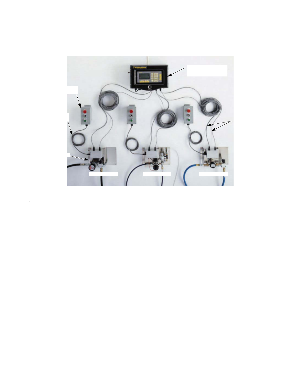
Remote
Operator Station
10’ (3.05 m) station
cable standard*
Fluid Panel
Overview
Main Components
ProDispense Controller
with display and
EasyKey™ pad
50’ (15.24 m) meter &
solenoid cables
FIG. 1
Oil/Lubricant Grease/Paint Water/Antifreeze
*20’ (6.1 m) station cable extension 198456 is available.
ProDispense Controller
The controller is used to setup the ProDispense system, fluids, and recipes, calibrate the
meters, and select a recipe or preset a dispense. The controller totalizers enable you to view
fluid dispense information and print the following reports:
• Alarm history report
• Totals report
• Configuration Setup report
• Fluid Setup report
• Recipe Setup report
• Run report
Display and EasyKey™ Pad
The EasyKey™ pad is the operator interface for the ProDispense system. The keypad consists of number keys, enter key, scrolling (arrow) keys, and operation (start, stop, clear, and
print) keys.
The graphic LCD screen displays system status, setup information, and operation options that
can be selected using the keypad.
309301G 9
Page 10
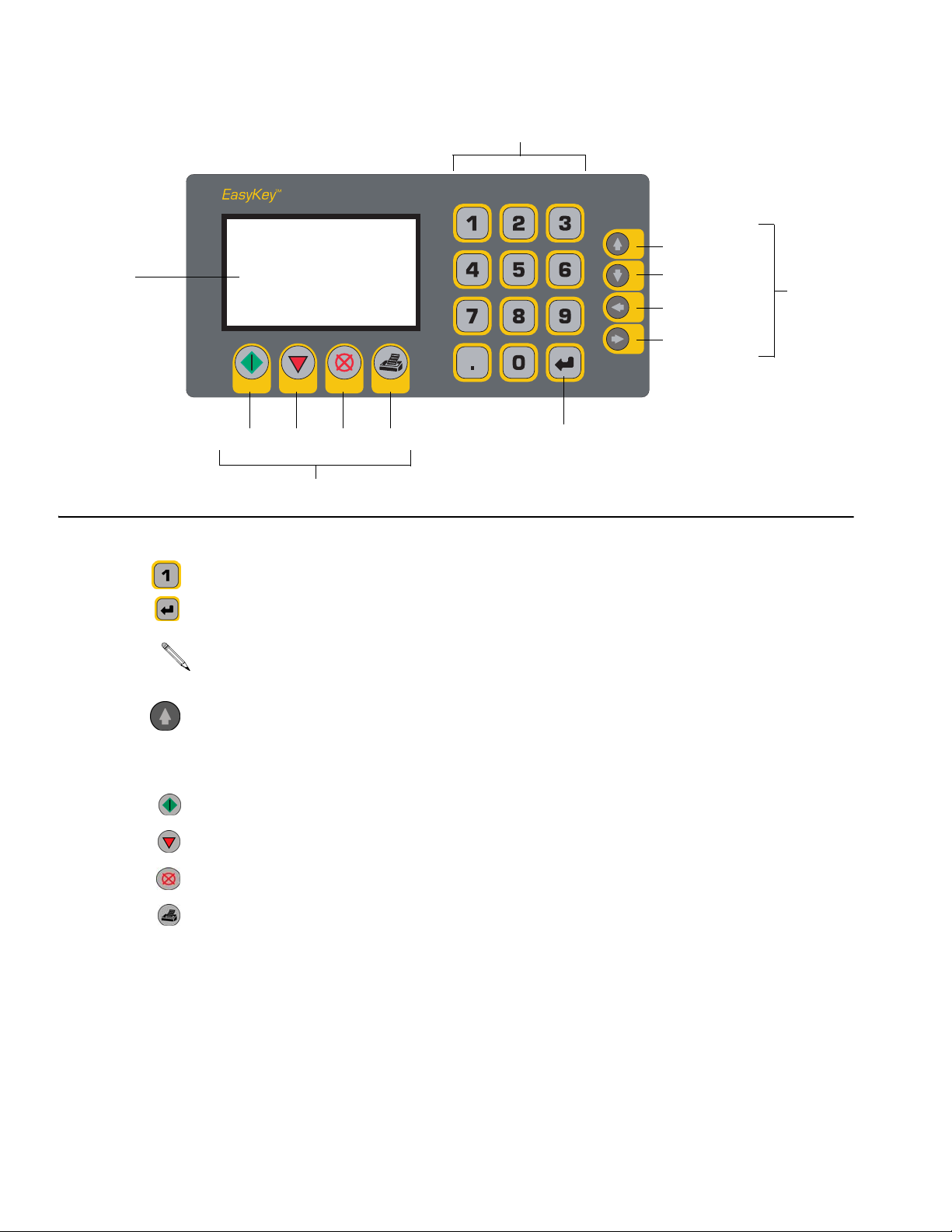
Number Keys
Overview
Previous Field
FIG. 2
Display
Start Stop Clear Print
Operation Keys
Next Field
Previous Screen
Next Screen
Enter
Key
Scrolling
Keys
Number Keys — type in setup or operation data.
Enter Key — press to accept and enter data.
If you press a scrolling key without pressing Enter, the cursor will move to the next field and
the information you typed will reset back to the previous data.
Scrolling Keys — press the up or down arrows to move between fields on the screen. Use the
left or right arrows to move between screens.
Operation Keys — use to operate the ProDispense system functions.
Start — press to start the current recipe dispense.
Stop — press to stop the current process.
Clear — press to clear an entry in an input field.
Print — press to print a report.
10 309301G
Page 11
Overview
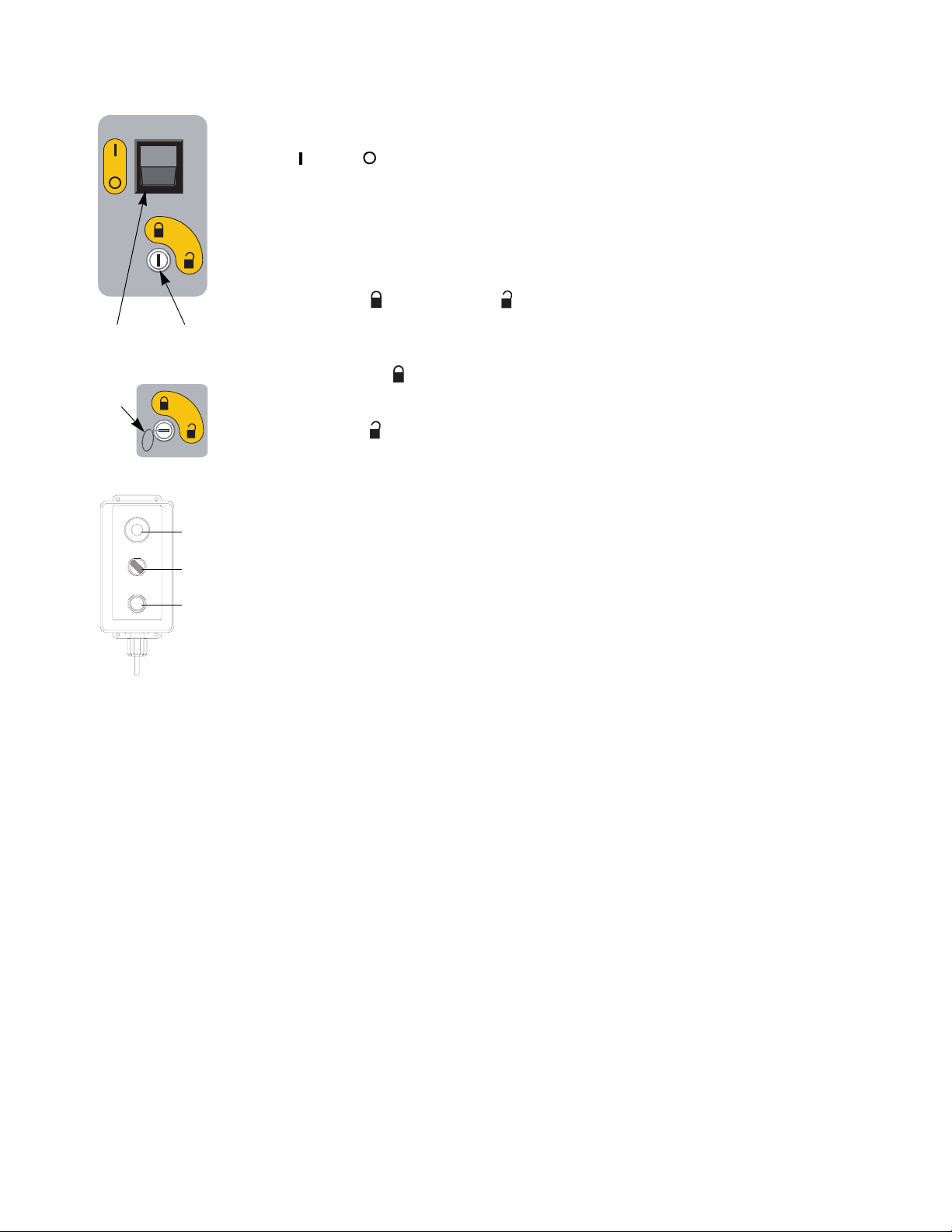
Power Switch (A)
On = Off = .
(On side of controller)
Operation Mode Switch (B) and Key (C)
The position of the switch (B) determines which mode of operation you are in:
Dispense Mode or Setup Mode . A key (C) supplied with the ProDispense system is
A
B
C
inserted into the switch and turned to change operation modes. The key cannot be removed
while the system is in Setup Mode.
Dispense Mode is used to dispense a recipe, fluid, check fluid totals, and to view the
alarms log.
Setup Mode is used to configure the system, fluid, and recipe parameters, and to cali-
brate the meters.
STOP
DISPENSE
AUTO ON
DISPENSE
START
ti1359a
Stop
button
Dispense
switch
Start
button
Remote Operator Stations
A cable connects the operator station to the fluid panel junction box. A separate operator station is needed for each fluid panel installed on the system. The dispense switch can be set to
dispense automatically (AUTO) or manually (ON).
If set to AUTO, the fluid panel will dispense when a recipe or fluid dispense is selected with
the controller and the start button is pressed either on the controller or the operator station.
The dispense will stop when the preset amount is reached or when the stop button is pressed
on either the controller or the operator station.
If set to ON, the fluid panel will begin dispensing immediately or when the dispense valve is
triggered. The dispense is stopped by releasing the trigger or turning the dispense switch to
AUTO or pressing the STOP button on the operator station.
309301G 11
Page 12
Overview
Fluid Panels
There are six types of fluid panels available:
• 244599 — Oil and Lubricant Fluid Panel
• 244600 — Water and Antifreeze Fluid Panel
• 244601 — Grease and Paint Fluid Panel
• 246837 — Grease and Paint Fluid Panel
• 246838 — Meterless Fluid Panel (meter supplied by user)
• 246839 — Grease and Paint Fluid Panel
There are three cable connections on the fluid panel junction box for connecting:
• operator station to the solenoid connection
• controller to solenoid connection
• controller to meter connection
Signals from the controller and operator station communicate to the fluid panel(s) when to
start and stop dispensing. Signals from the fluid panel’s fluid meter communicate to the controller how much fluid has been dispensed.
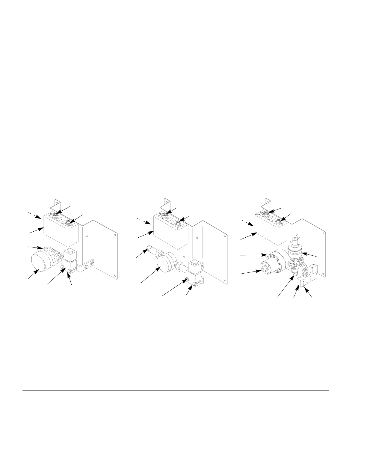
A
C
244599 244601
A
B
C
244600
B
A
B
C
D
E
D
E
F
G
H
ti1433a
F
G
H
ti1434a
D
E
F
H
G
J
ti1435a
I
Key
A Controller Solenoid Connection
B Controller Meter Connection
C Operator Station Connection
D Junction Box
E Fluid Inlet
F Meter
G Solenoid
H Fluid Outlet
I Air Inlet
J Fluid Valve
FIG. 3
12 309301G
Page 13
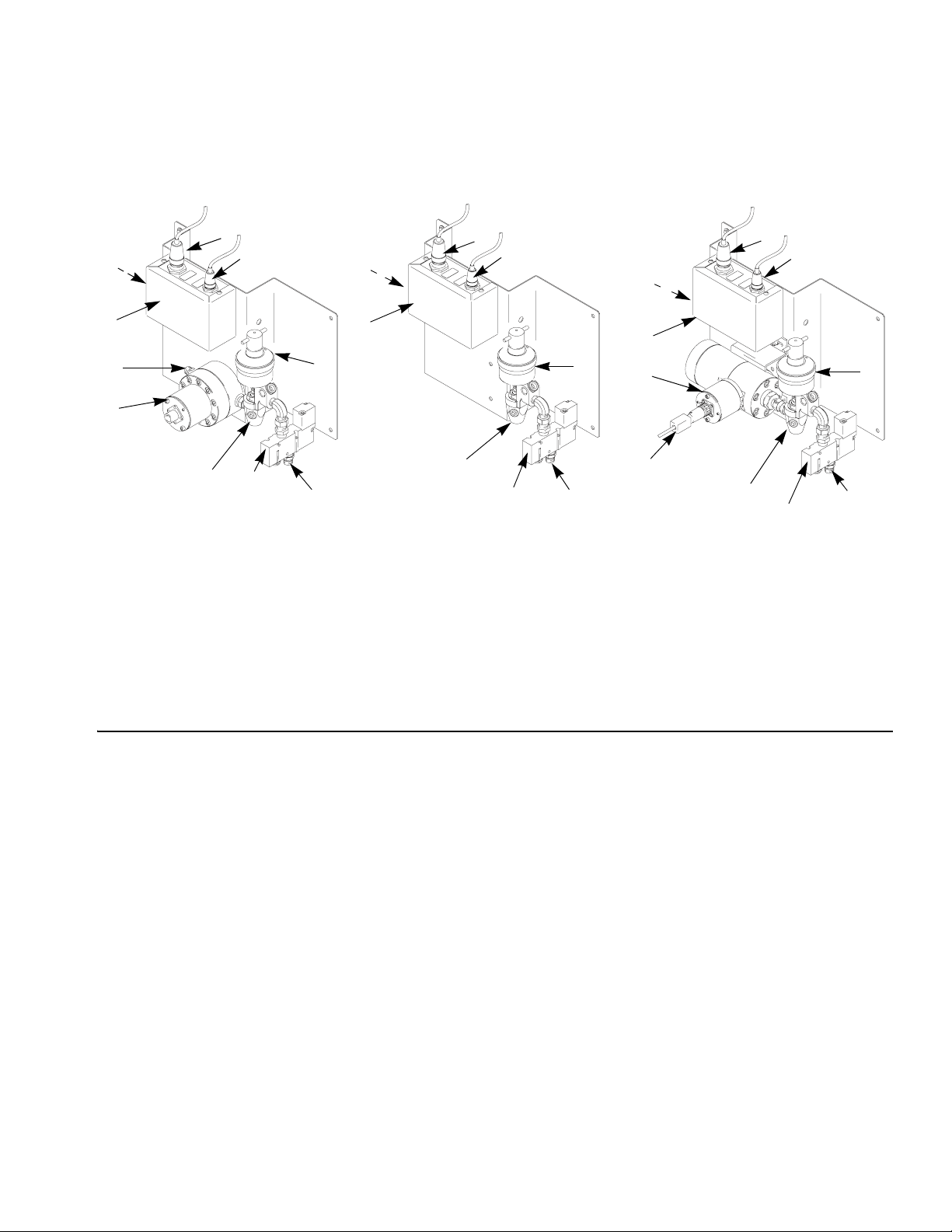
Overview
C
D
E
F
FIG. 4
B
246838
A
B
C
246837 246839
A
B
C
A
D
D
J
H
H
G
I
G
Key
A Controller Solenoid Connection
B Controller Meter Connection
C Operator Station Connection
D Junction Box
E Fluid Inlet
F Meter
G Solenoid
H Fluid Outlet
I Air Inlet
J Fluid Valve
J
E
J
F
I
H
I
G
309301G 13
Page 14

Installation
Do not install or service this equipment unless you are trained and qualified.
Do not install the ProDispense controller, fluid panels, or remote operator station in a
hazardous location.
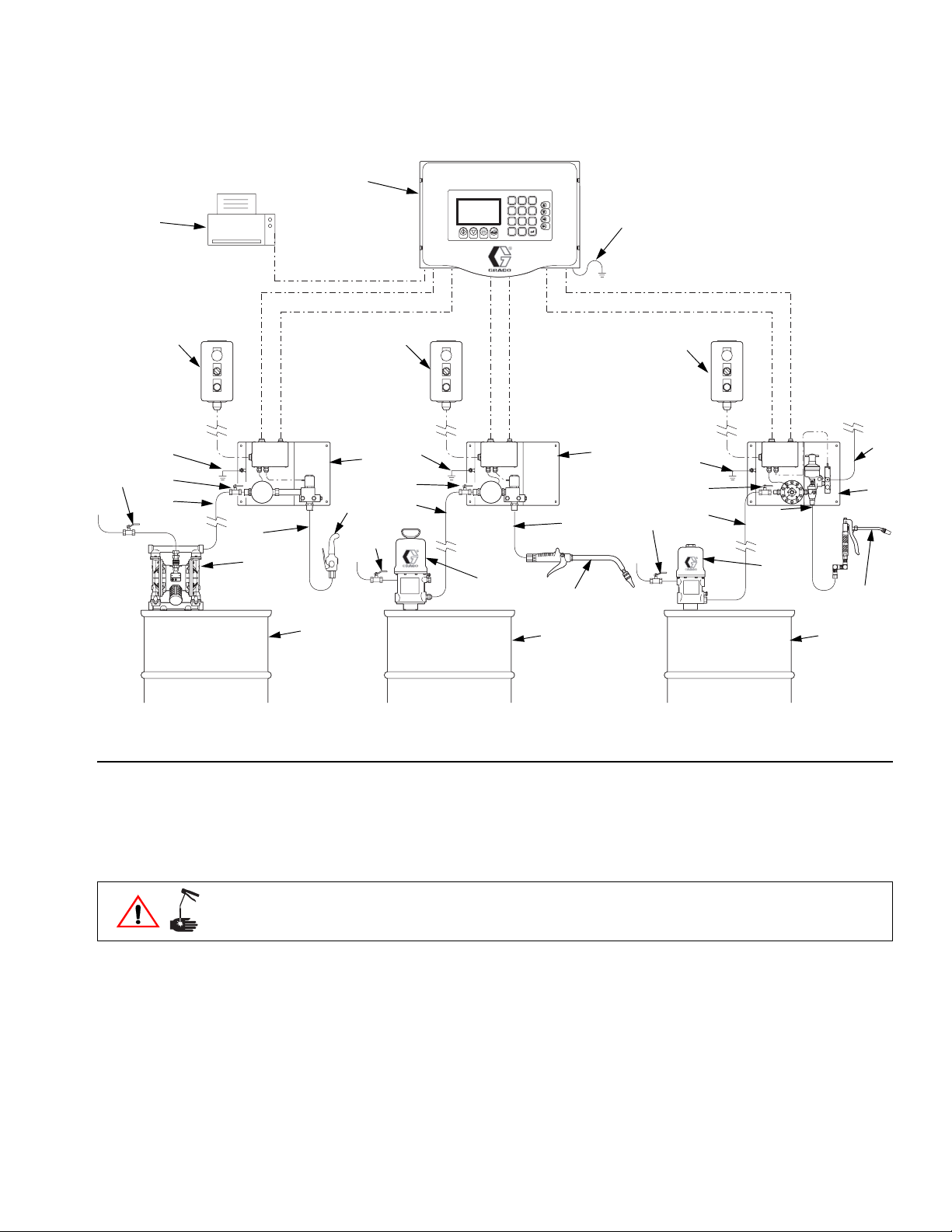
• FIG. 5 is not an actual system design. Contact your Graco distributor for assistance in
• See detailed installation instructions, beginning on page 18.
• Be sure all accessories are adequately sized and pressure rated to meet the system
• Be sure mounted surfaces and fasteners can support the weight of the equipment; hose,
Installation
designing your system.
requirements.
tubing and cable attachments; and fluid.
Key for F
1 ProDispense Controller with EasyKey™ Pad
2 Remote Operator Station
3 Oil/Lubricant Fluid Panel (244599)
4 Water/Antifreeze Fluid Panel (244600)
5 Grease/Paint Fluid Panel (244601)
6 Fluid Supply Pump
7 Fluid Supply
8 Air Supply Line
9 Dispense Valve
10 Ground Wire to true earth ground
11 Fluid Supply Line
12 Fluid Dispense Line
13 Fluid Shutoff Valve
14 Bleed-type Air Shutoff Valve
15 Optional Printer
IG. 5
14 309301G
Page 15
Installation
14
15
10
13
11
1
EasyKey
TM
123
456
789
0
.
2
2
10
4
13
9
12
11
12
14
6
6
9
10
2
3
10
13
14
11
12
8
5
6
9
7
FIG. 5: ProDispense System - Typical Installation
Install the Fluid Supplies
For maintenance and safety, you must install:
• a fluid shutoff valve between each fluid supply line and the ProDispense fluid panel.
• a bleed-type air shutoff valve on the air supply line to the fluid supplies.
The ProDispense fluid panels can be supplied by pressure tanks, pail or drum pumps, or central recirculating lines.
The fluid supply must be free of pressure spikes, commonly caused by a pump stroke
changeover. If necessary, install pressure regulators or a surge tank on the fluid supply outlets. Note that this will also reduce the fluid supply pressure.
7 7
ti1361a
309301G 15
Page 16
Installation
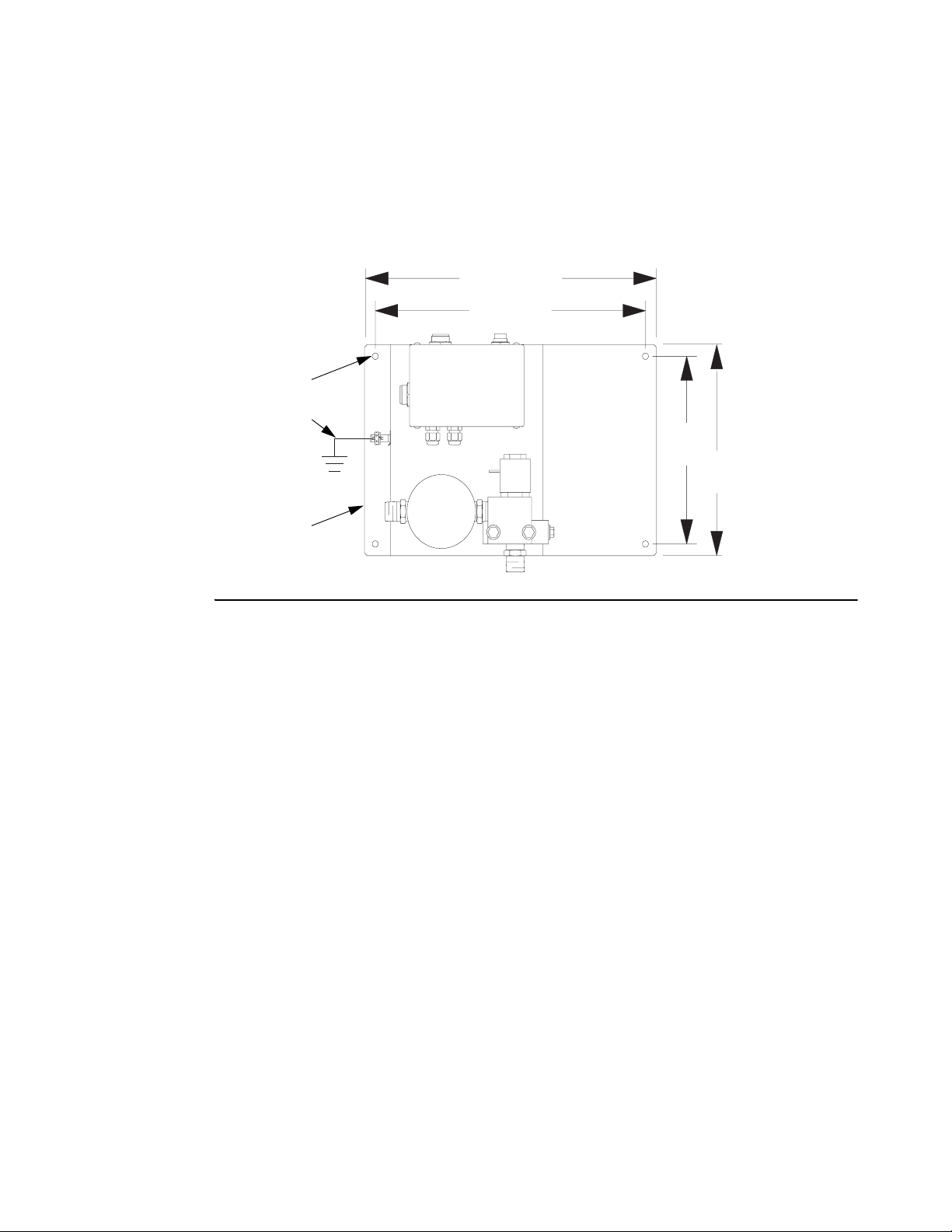
Mount the Fluid Panel(s)
Mount the fluid panel(s) on a flat, sturdy surface. Install 1/4” or M6 fasteners in the four 0.28”
mounting holes (C1) and secure the fluid panel (C) to the mounting surface. Connect a
ground wire (G) as instructed on page 20.
13.4”
(315 mm)
12.4”
(340 mm)
C1
G
8”
(203 mm)
9”
(229 mm)
C
ti1357a
FIG. 6
Connect the Air and Fluid Lines
Fluid Panel 244599 and 244600
Connect the fluid supply line (11) to the 1/2” npt(f) meter inlet. See FIG. 5. Connect a fluid dis-
pense line (12) to the 1/2” npt(f) solenoid outlet. Connect the other end to the dispense valve
(9).
Fluid Panel 244601 and 246837
Connect an air supply line (8) to the 1/4” npt(f) solenoid valve port. The air supply must be filtered to 10 micron to lengthen solenoid valve life.
Connect the fluid supply line (11) to the 1/4” npt(f) meter inlet. Connect a fluid dispense line
(12) to the 3/8” npt(m) outlet of the dispense valve on the fluid panel. Connect the other end to
the dispense valve (9).
16 309301G
Page 17
Installation
Fluid Panel 246838
Connect an air supply line (8) to the 1/4” npt(f) solenoid valve port. The air supply must be filtered to 10 micron to lengthen solenoid valve life.
Connect the fluid supply line (11) to the meter inlet. Connect a fluid dispense line (12) to the
3/8” npt(m) outlet of the dispense valve on the fluid panel. Connect the other end to the dispense valve (9).
Fluid Panel 246839
Connect an air supply line (8) to the 1/4” npt(f) solenoid valve port. The air supply must be filtered to 10 micron to lengthen solenoid valve life.
Connect the fluid supply line (11) to the 3/4” npt(f) meter inlet. Connect a fluid dispense line
(12) to the 3/8” npt(m) outlet of the dispense valve on the fluid panel. Connect the other end to
the dispense valve (9).
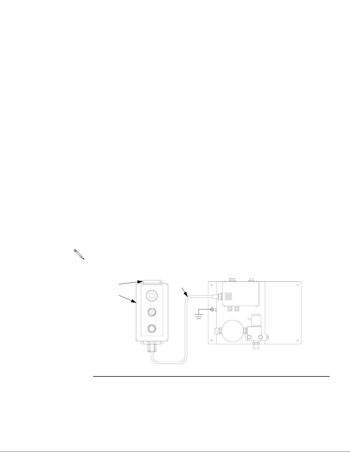
Install the Remote Operator Station
Mount the operator station (D) in a convenient location for the operator. Secure it with No. 10
or M5 fasteners through the four 0.22” mounting holes (D1). Connect the cable (D2) to the
fluid panel junction box connector marked
20 ft. (6.1 m) station cable extension 198456 is available.
D1
D
D2
C.
C
ti1451a
FIG. 7
309301G 17
Page 18
Installation
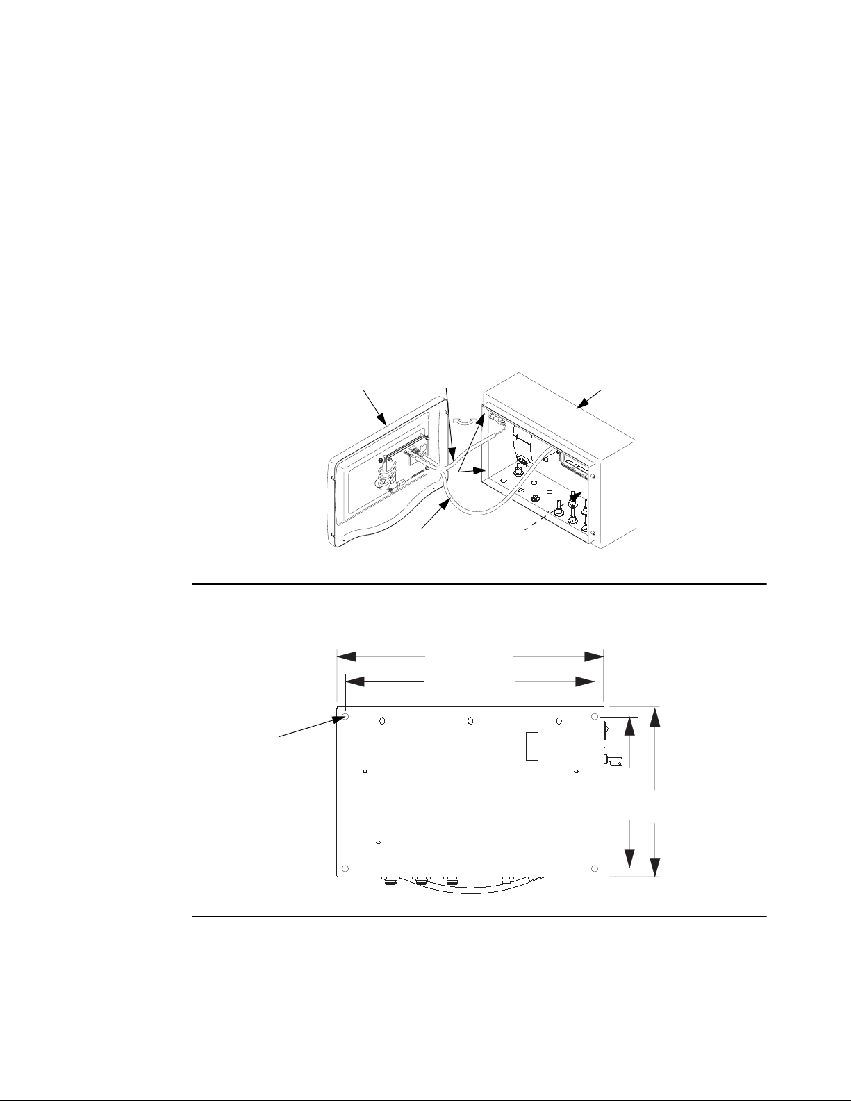
Mount the Controller
Mount the controller on a flat, sturdy surface as instructed below.
1. Loosen the four screws (A1), disconnect the two cables (A2, A3) and remove the controller cover (A).
2. Install 0.44” or M11 fasteners in the four 0.51” mounting knockouts (B1) and secure the
controller (B) to the mounting surface.
3. Reconnect the cables (A2, A3).
4. Install the controller cover (A) and secure it with the screws (A1).
FIG. 8
B1
A2
A3
A1
(441 mm)
(368 mm)
17.38”
14.5”
B1
B
TI1436a
8.5”
(216 mm)
11.3”
(287 mm)
A
TI1453A
FIG. 9
18 309301G
Page 19
Installation
Connect the Cables and Power Cord
On the bottom of the controller, there are meter and solenoid cable connectors for three Fluid
panels. The row of connectors marked
row of connectors marked
cables as instructed below.
1B, 2B, and 3B are for meter cable connections. Connect the
1A, 2A, and 3A are for solenoid cable connections. The
1. Connect the solenoid cable (E) between controller connector
first fluid panel.
2. Connect the meter cable (F) between controller connector
fluid panel.
3. Repeat the cable connection for each of the fluid panels installed in the system (
1A and connector A on the
1B and connector B on the first
2A to A,
2B to B, etc.).
A knockout, marked , is provided for a customer supplied power input (P) cable with strain
relief or for wire conduit.
F
P
FIG. 10
309301G 19
E
TI1438a
Page 20
Installation
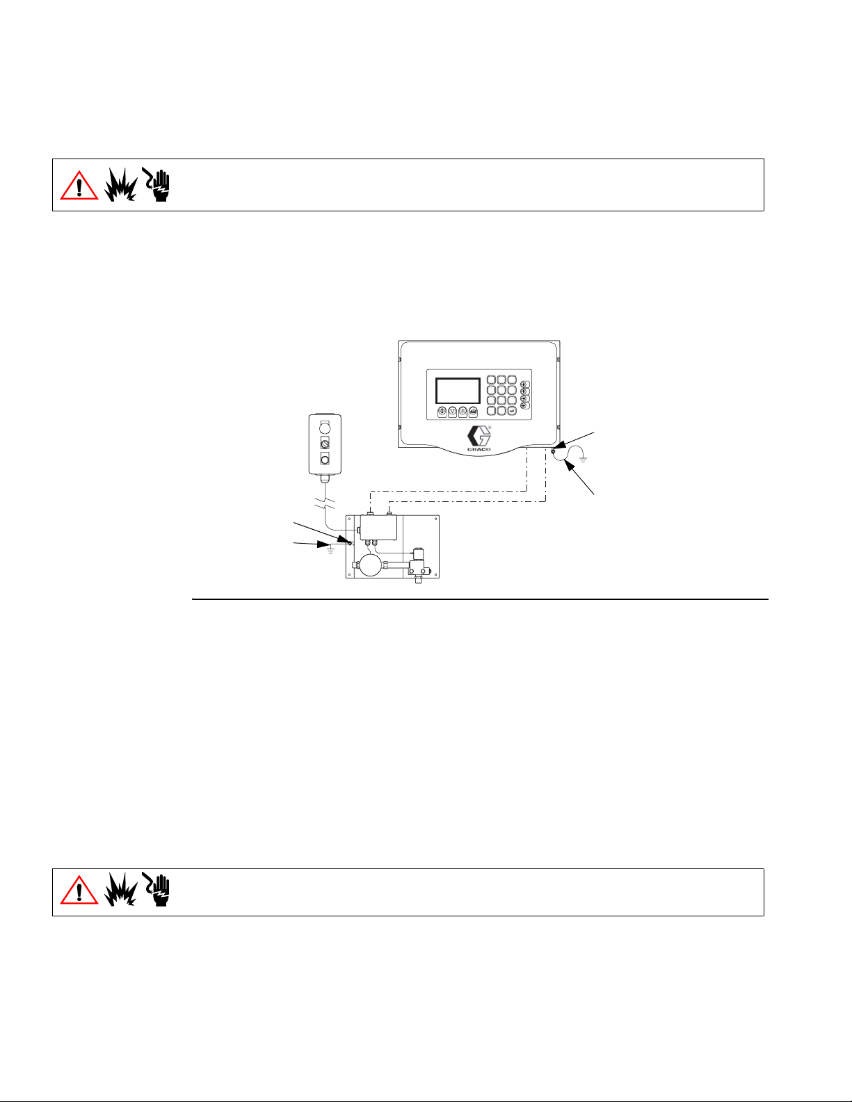
Ground the System
The system must be properly grounded. Follow the instructions here and on page 6.
ProDispense Controller: Connect a ground wire (G1) to the grounding lug (H1) on the bottom
of the controller. Connect the other end of the ground wire to a true earth ground.
Fluid Panels: Connect a ground wire (G) to the grounding lug (H) on the junction box bracket.
Connect the other end of the ground wire to a true earth ground.
EasyKey
TM
123
456
789
0
.
H1
G1
H
G
TI1439a
FIG. 11
Feed Pumps or Pressure Pots: See your separate pump or pressure pot manual.
Air and Fluid Hoses: Use only grounded hose.
Fluid Supply Container: Ground the container according to your local code.
Solvent Pails Used when Purging: Ground pails according to your local code. Use conductive,
metal pails, placed on a grounded surface. Do not place pails on nonconductive surfaces,
such as paper or cardboard.
Check the Resistance
To reduce the risk of fire, explosion, or electric shock, the resistance between the ProBatch
components and true earth ground must be less than 1 ohm.
Have a qualified electrician check the resistance between each ProDispense component and
true earth ground. If the resistance is 1 ohm or greater, a different ground site may be
required. Do not operate the system until the problem has been corrected.
20 309301G
Page 21
Installation
Connect a Printer (optional)
Connect the 5 ft. (1.52 m) printer cable (provided with printer kit 239873) between the printer
and controller printer connector marked . See F
Accessory Printer Cable 198669, 50 ft. (15.24 m) long, is available. Do not use longer cables.
IG. 5, page 15.
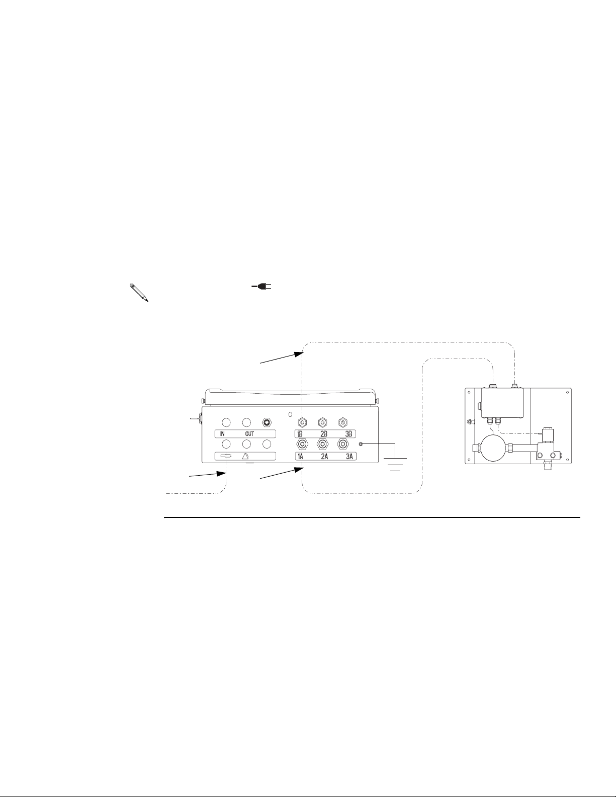
Connect to a PC or Alarm (optional)
The ProDispense system can be connected to a PC via Modbus RTU network protocol (6)
and/or audible alarms (7) as shown in F
instructions on page 26 to setup modbus station number and recipe selection. Contact your
Graco distributor for Modbus address mapping list.
IG. 12. Refer to field wiring chart, page 60. Follow
5
4
7
1
3
1
4
6
2
5
3
TI1454A
2
FIG. 12
309301G 21
Page 22

Before Beginning Operation
• Check all fluid and air connections for correctness and tightness.
• Follow the Startup procedure on page 23.
Installation
22 309301G
Page 23

Startup
Startup
Follow this procedure to start the ProDispense system for the first time (initial startup) or after
the system has been shut down.
1. Turn on the power. The ProDispense system startup screen will display while the system
is starting, then the Run screen (page 30) or System Setup screen (page 26) will appear,
depending on the mode of operation the system is in. For an explanation of operation
modes, see page 11.
FloSync
Startup screen
ProDispense: Rev. X.XX
2. If this is the initial startup, change to Setup Mode (page 25) and complete the setup procedures.
3. Change to the Dispense Mode Run screen if you are not there already (page 29).
4. Make sure the dispense lines run into the proper reservoir.
5. Load the fluids (page 34).
Software revision
309301G 23
Page 24

Pressure Relief Procedure
Follow this procedure to relieve pressure in the fluid panel and dispense line before cleaning,
checking, or servicing the equipment or installing or cleaning a dispense valve nozzle.
Follow the additional instructions in brackets if a dispense valve is installed on the
dispense line.
1. Shut off the fluid supply to the ProDispense fluid panel. Follow the Pressure Relief Proce-
STOP
dure for the fluid supply system.
Pressure Relief Procedure
DISPENSE
AUTO ON
DISPENSE
START
Dispense
Switch ON
2. Place the dispense line [or direct the dispense valve] into a waste container.
3. To begin dispensing, turn the Operator Station dispense switch to ON [and trigger the
ti1360a
4. When fluid stops flowing and pressure is relieved, [release the dispense valve trigger and]
STOP
DISPENSE
AUTO ON
DISPENSE
START
Dispense
Switch AUTO
ti1359a
5. Repeat the process for each fluid panel as needed.
Shutdown
Follow this procedure before servicing the equipment and to avoid having fluid dry in the
equipment and fluid lines when the equipment is not being operated.
dispense valve].
turn the dispense switch to AUTO to stop dispensing.
1. Purge the system until it is clean (page 35).
2. Relieve the pressure as instructed above.
3. Turn off the ProDispense controller power switch.
24 309301G
Page 25

Setup Mode
Screen Navigation
To enter Setup Mode:
Setup
Mode
You must have the key supplied with the system. Insert the key into the switch and turn it to
Setup Mode . The System Setup screen appears.
Do not turn the key to Setup Mode while the ProDispense is dispensing or the system will
abort the dispense.
Setup Mode
SYSTEM SETUP
Day/Month/Year: Dispense Mode:
1=Fluid Station
Hour:Minute 2=Recipe
Language:
1=English 2=Spanish 2=Network
3=German 4=French
5=Japanese Station Number:
System Fluids Recipes Meters
current screen
The name of the screen that is currently displayed is highlighted.
Press the left or right arrow keys on the keypad to move through the screens.
Press the up or down arrow keys to move through data fields on the screen.
Recipe Selection:
1=User Interface
System Setup Screen
4 screen selections
To exit Setup Mode:
Turn the key to Dispense Mode. The Run screen appears. Refer to page 30.
309301G 25
Page 26

Setup Mode
System
Day/Month/Year: Dispense Mode:
Hour:Minute 2=Recipe
Language:
1=English 2=Spanish 2=Network
3=German 4=French
5=Japanese Station Number:
System Fluids Recipes Meters
System Setup Screen
Use system setup to enter the date, time, language to display, dispense mode, means of recipe selection and station number.
SYSTEM SETUP
1=Fluid Station
Recipe Selection:
1=User Interface
To setup the system:
1. Type the current date: day (1-31) ,
month (1-12) , year (2000-2099) .
2. Type the current time: hour (0-23) ,
minute (0-59) .
The ProDispense clock is a 24 hour clock. The date
and time are used for date/time stamps on alarms
and reports.
3. Type the desired language number (1-5).
Power must be cycled before the language change
will take affect.
4. Type the number for the desired dispense mode
(1-2).
Fluid Station: use this mode to select individual
fluid stations when dispensing.
Recipe: use this mode to select a recipe when dispensing. Dispensing by recipe will signal all fluid stations included in the recipe to dispense
simultaneously.
5. Type the number for the desired recipe selection
(1-2).
User Interface: use to select recipes from the
EasyKey pad.
Network: use to select recipes from a networked
source.
6. Type the station number (1-99).
This number is used for network communications to
identify the station. Each station must have a
unique number.
7. Press the right arrow key to go to the Fluid Setup
screen.
26 309301G
Page 27

Setup Mode
Fluids
Units of Measure
1=cc 2=oz 3=Qt
4=Ltr 5=Gal
Tolerance %
Timeout Value (min)
K-factor (cc/pulse)
System Fluids Recipes Meters
Fluid Setup Screen
Use fluid setup to designate the parameters for each fluid you will dispense.
Fluid parameters must be set before the fluid can be used in a recipe.
FLUID SETUP
Fluid 1 Fluid 2 Fluid 3
To set up the fluids:
You can have 1-3 fluid panels connected to the ProDispense controller. Setup the fluids for each of your fluid
panels as follows:
1. Type the number for the desired units of measure
(1-5).
2. Type the dispense tolerance percentage (1-99).
3. Type the timeout value in minutes (1-99).
If a dispense does not complete by the end of the
entered value, a Dispense Timeout alarm occurs.
See page 33.
4. Type the fluid meter’s K-factor (cc/pulse).
Fluid Panel
part no.
244599 oil/lubricant 4.73
244600 water/antifreeze 25
244601 grease/coating 0.119
246837 grease/coating .061
246838 grease/coating n/a
246839 grease/coating 0.286
The K-factors in the table are a starting point. You
can calibrate the meter as instructed on page 28.
5. Repeat steps 1-4 for each additional fluid panel.
6. Press the right arrow key to go to the Recipe
Setup screen.
Meter Type K-factor
(cc/pulse)
309301G 27
Page 28

Setup Mode
Recipes
Target Amount
Type in 0 for Target Amount if Fluid
System Fluids Recipes Meters
Meters
Recipe Setup Screen
Use recipe setup to configure your recipes by assigning a recipe number and designating Target Amounts for each fluid in the recipe.
RECIPE SETUP
Fluid 1 Fluid 2 Fluid 3
ltr ltr ltr
is not used in this Recipe.
*
Calibrate Meter Screen
Use this screen to calibrate your fluid panel meters. All values are in cubic centimeters (cc).
Follow the additional instructions in brackets if a dispense valve is installed on the
dispense line.
To setup the recipes:
1. Type a recipe number (1-250).
2. Type the Target Amount for each fluid used in the
recipe (0-999.99).
Type in 0 if a fluid is not used in the recipe. The
units of measure are set in Fluid Setup (page 27).
3. Press the right arrow key to go to the Calibrate
Meter screen.
CALIBRATE METER
K-factor
(cc/pulse)
Fluid 1 04.730 0
Fluid 2 00.119 0
Fluid 3 25.000 0
1) Manually dispense fluid into a calibrated container
(minimum of 300 cc).
2) Type in Actual Value and Press ENTER.
System Fluids Recipes Meters
Dispensed
(cc)
Actual
(cc)
To calibrate a meter:
1. Dispense fluid into a calibrated container (minimum
300 cc) by turning the Operator Station dispense
switch to ON [and triggering the dispense valve].
2. Stop dispensing by [releasing the dispense valve
trigger and] turning the dispense switch to AUTO.
3. The amount the controller detected was dispensed
appears on the screen in the Dispensed column. If
the value in the column differs from the measured
amount in the container, enter the measured value
(in cc) in the Actual column.
If nothing is entered in the Actual column, the K-factor remains unchanged.
4. The controller will calculate the meter K-factor and
display the new value in the K-factor column.
5. Repeat the process for each of your fluid panels.
28 309301G
Page 29

Dispense Mode
Screen Navigation
Dispense Mode is used to dispense a fluid or recipe, check fluid dispense totals, and view
Dispense
Mode
the alarms log.
Target 005.00 ltr 050.00 ltr 010.10 ltr
Actual 5.00 ltr 51.00 ltr 10.00 ltr
Tolerance % 555
Difference % 0+2-1
RECIPE DISPENSE ID#
Fluid 1 Fluid 2 Fluid 3
Idle Idle Idle
Dispense Mode
Recipe Dispense screen
AUTO
Run Totals Alarms
current screen
The name of the screen that is currently displayed is highlighted.
The Operator Station dispense switch must be set to AUTO to dispense using the controller.
Press the left or right arrow keys on the keypad to move through the screens.
Press the up or down arrow keys to move through data fields on the Run screen.
3 screen selections
309301G 29
Page 30

Dispense Mode
Run
Run Screen
Use the Run screen to dispense a recipe or individual fluids. The Run screen displays either
Recipe Dispense or Fluid Dispense, depending on which Dispense Mode was selected in
System setup.
Idle, Dispense, and Alarm Status
In each of the fluid columns, under the Fluid panel number, is a status line, which shows the
status of the associated fluid panel. The three possible statuses are:
Idle — fluid panel is idle (not dispensing).
Dispense — fluid panel is dispensing.
Alarm — controller has detected the fluid panel has an alarm condition. To view alarm
information, press the right arrow key twice to move to Alarm screen. Refer to page 33.
Status line
RECIPE DISPENSE
Fluid 1 Fluid 2 Fluid 3
Idle Idle Idle
Target 005.00 ltr 050.00 ltr 010.10 ltr
Actual 5.00 ltr 51.00 ltr 10.00 ltr
Tolerance % 555
Difference % 0+2-1
ID#
Recipe Dispense
Recipe Dispense displays in the Run screen if “Recipe”
is selected as the Dispense Mode. Recipe Dispense is
used to dispense a set amount of fluid, typically from
more than one fluid panel simultaneously.
1. Place the dispense lines into the receptacle(s) you
2. Set the Operator Station dispense switch to AUTO.
want to dispense into.
Run Totals Alarms
Start
STOP
DISPENSE
AUTO ON
DISPENSE
START
ti1359a
Dispense
Switch AUTO
START
3. Type the desired recipe number (1-250).
The Target value is set in Recipe Setup. You cannot
change it in the Run screen.
4. Type a 4 digit ID# if desired.
5. Press the Start button on the Controller or on the
Remote Operator Station to begin dispensing the
recipe.
6. As the fluids dispense, their statuses on the screen
change from Idle to Dispense and the amounts dispensed appear in the Actual row.
7. Each fluid panel stops dispensing when its individual
Target is reached.
30 309301G
Page 31

Dispense Mode
Target
Status line
FLUID DISPENSE ID#
Fluid 1 Fluid 2 Fluid 3
Idle Idle Idle
005.00 ltr 050.00 ltr 010.10 ltr
Fluid Dispense
Fluid Dispense displays in the Run screen if “Fluid Station” is selected as the Dispense Mode. Fluid Dispense
allows you to select a fluid panel and the amount to dispense on an individual basis.
Actual 5.00 ltr 51.00 ltr 10.00 ltr
1. Place the fluid panel dispense line into the recepta-
Tolerance % 555
Difference % 0+2-1
Run Totals Alarms
2. Type a 4 digit ID# if desired.
3. In the column for the fluid you want to dispense, type
4. Press the Start button on the Remote Operator Sta-
5. As the fluid dispenses, the status on the screen
STOP
DISPENSE
AUTO ON
DISPENSE
START
ti1359a
Dispense
Switch AUTO
START
6. The fluid panel stops dispensing when its Target is
cle.
the desired amount of fluid in the Target field.
tion to begin dispensing the fluid.
changes from Idle to Dispense and the amount dispensed appears in the Actual row.
reached.
309301G 31
Page 32

Dispense Mode
Totals
Fluid Totals Screen
Press the left or right arrow key to select Totals. The Fluid Totals screen shows how
much of each of the fluids has been dispensed overall. Two totals are shown. Grand totals are
tracked from the time the system is first started up and they are not resettable. Resettable
totals show the total amount of each fluid dispensed since the last reset.
FLUID TOTALS
Fluid# Resettable Grand
1 00005.1 ltr 00312.1 ltr
2 00005.2 ltr 00582.8 ltr
3 00004.8 ltr 00468.2 ltr
Press ENTER and CLEAR to reset totals
Run
To tal s A l ar m s
Clear Print
Last Reset
Date:23/04/01
Time: 07:35
Press Print key to print Fluid Totals Report.
Press Clear and Enter keys simultaneously to reset all
resettable totals.
All resettable totals are reset when Clear and
!
Enter are pressed. Fluid totals cannot be reset
+
individually.
32 309301G
Page 33

Dispense Mode
Alarms
Date Time Description Recipe Fluid
03/09 9:39 Invalid K-factor 10 1
03/08 14:32 Out of Tolerance 0 1
03/05 15:01 Timeout 6 2
03/05 8:12 Out of Tolerance 62
03/02 10:59 Invalid K-factor 0 3
Run Totals
Alarm History Screen
Press the left or right arrow key to select Alarms. This screen summarizes the last five
alarms that have occurred.
ALARMS
Alarms
Print
Press Print key to print an Alarms Report.
Out of Tolerance Alarm
This alarm occurs when the current actual dispense is either less than target – tolerance or
greater than target + tolerance.
Dispense Timeout Alarm
The controller stops an active dispense and initiates this alarm when the current dispense is
not finished by the end of the Timeout. Timeout is a value entered during Fluid Setup (page
27).
Invalid K-factor Alarm
This alarm occurs if the meter K-factor is set to zero (00.000).
Memory Failure Alarm
This alarm occurs when the memory has been replaced but not programmed or when the
memory has become corrupt.
See page 36 for alarm troubleshooting information.
309301G 33
Page 34

Operation Procedures
Wear eye protection whenever you are dispensing fluid.
Follow the additional instructions in brackets if a dispense valve is installed on the
dispense line.
Loading Fluid Lines
Follow this procedure to load the fluid lines and purge out any air:
1. Place the dispense line [or direct the dispense valve] into a waste container.
1. To begin loading fluid, turn the Operator Station dispense switch to ON [and trigger the
dispense valve].
Operation Procedures
DISPENSE
AUTO ON
DISPENSE
START
2. Continue dispensing until all air is purged from the fluid line and fluid flows steadily from
the valve.
3. Turn the dispense switch to AUTO to stop dispensing.
Manual Dispense
1. Place the dispense line [or direct the dispense valve] into the reservoir.
STOP
ti1360a
STOP
Dispense
Switch ON
START
2. To begin dispensing, turn the Operator Station dispense switch to ON [and trigger the dispense valve].
3. Turn the dispense switch to AUTO [or release the dispense valve trigger] to stop dispensing.
Automatic Dispense
Refer to page 30 for instructions on dispensing a recipe or page 31 to dispense individual
fluids.
34 309301G
Page 35

Operation Procedures
Purging Fluid
Follow this procedure to purge the fluid lines:
1. Connect the fluid supply line to a solvent supply. Set the fluid supply pressure as low as
possible to avoid splashing.
2. To begin purging the lines, direct the fluid outlet into a grounded metal pail, turn the Operator Station dispense switch to ON [and trigger the dispense valve].
3. Continue dispensing until fluid lines are clean.
4. Turn the dispense switch to AUTO or [release the dispense valve trigger] to stop dispensing.
5. If you are loading a new material, connect the fluid supply line to the new fluid supply, and
follow the procedure for Loading Fluid Lines.
Emergency Stop
RECIPE DISPENSE
ID#
To stop fluid flow at all the fluid panels connected to the
controller, press the Stop button on the controller.
Fluid 1 Fluid 2 Fluid 3
Idle Idle Idle
Target 005.00 ltr 050.00 ltr 010.10 ltr
Actual 000.00 ltr 000.00 ltr 000.00 ltr
Tolerance % 555
Difference % -98 -99 -97
Run Totals Alarms
Stop
To stop fluid flow at an individual fluid panel, press the
STOP
DISPENSE
AUTO ON
DISPENSE
START
STOP
ti1359a
STOP button on the Operator Station connected to the
fluid panel.
309301G 35
Page 36

Troubleshooting
Problem Cause Solution
Troubleshooting
Out of Tolerance Alarm Dispense is under or over tolerance
limit set for the fluid.
Dispense Timeout Alarm The dispense did not complete within
set Dispense Timeout value.
Run screen shows tolerance difference for last
dispense. Use the value to determine whether
you should:
• Increase the tolerance value
• Model 244601 only — increase fluid flow
by further opening the dispense valve
(turn the t-handle clockwise).
• Increase or decrease fluid flow rate of the
fluid supply.
Check the following:
• Fluid supply container is not empty.
• Fluid supply equipment is not faulty.
• Fluid flow rate is sufficient.
• Timeout value is too low and needs
increase.
• Fluid line is not clogged.
• Solenoids are operating.
• Model 244601 only — solenoid is receiv-
ing air and dispense valve is open.
• Cables are properly connected.
• Meters are operating and communicating
with controller.
• Dispense valves are operating.
Service equipment as needed.
Invalid K-factor Alarm Meter K-factor is set to zero (00.000). Set valid meter K-factor (page 27).
Memory Failure Alarm The system is not configured. Enter setup values (page 25).
The memory is corrupt. Replace flash EPROM.
No display No power Turn on or reconnect power.
Faulty cable(s) Replace cable(s).
Blown fuse(s) Replace fuse(s).
36 309301G
Page 37

Service
Service
Removing and Installing Controller
Wear a grounding strap when replacing any of the controller boards to avoid shorting them
out.
Check with your Graco distributor periodically to see if circuit board or software updates are
available.
To remove controller:
1. Turn off controller power switch.
2. Disconnect meter (F), solenoid (E), and power (P) cables and ground wire (G) from the
bottom of the controller (B). See F
IG. 13.
.
F
F
G
B
P
P
FIG. 13
3. Loosen the four screws (A1) and carefully remove the controller cover (A). See FIG. 14.
4. Disconnect cable connectors (A2, A3) from the display board.
5. Remove the four bolts (B1) and remove the control box. (B).
E
TI1438a
309301G 37
Page 38

To install controller:
6. Secure controller (B) to the mounting surface with four bolts (B1).
Service
7. Plug two connectors (A2, A3) into the display board. See F
IG. 14.
8. Install controller cover (A) and secure it with four screws (A1).
9. Reconnect ground wire (G) and power (P), meter (F), and solenoid (E) cables to the controller. See F
IG. 13.
A3
B
A
A1
A2
B1
TI1436a
FIG. 14
38 309301G
Page 39

Service
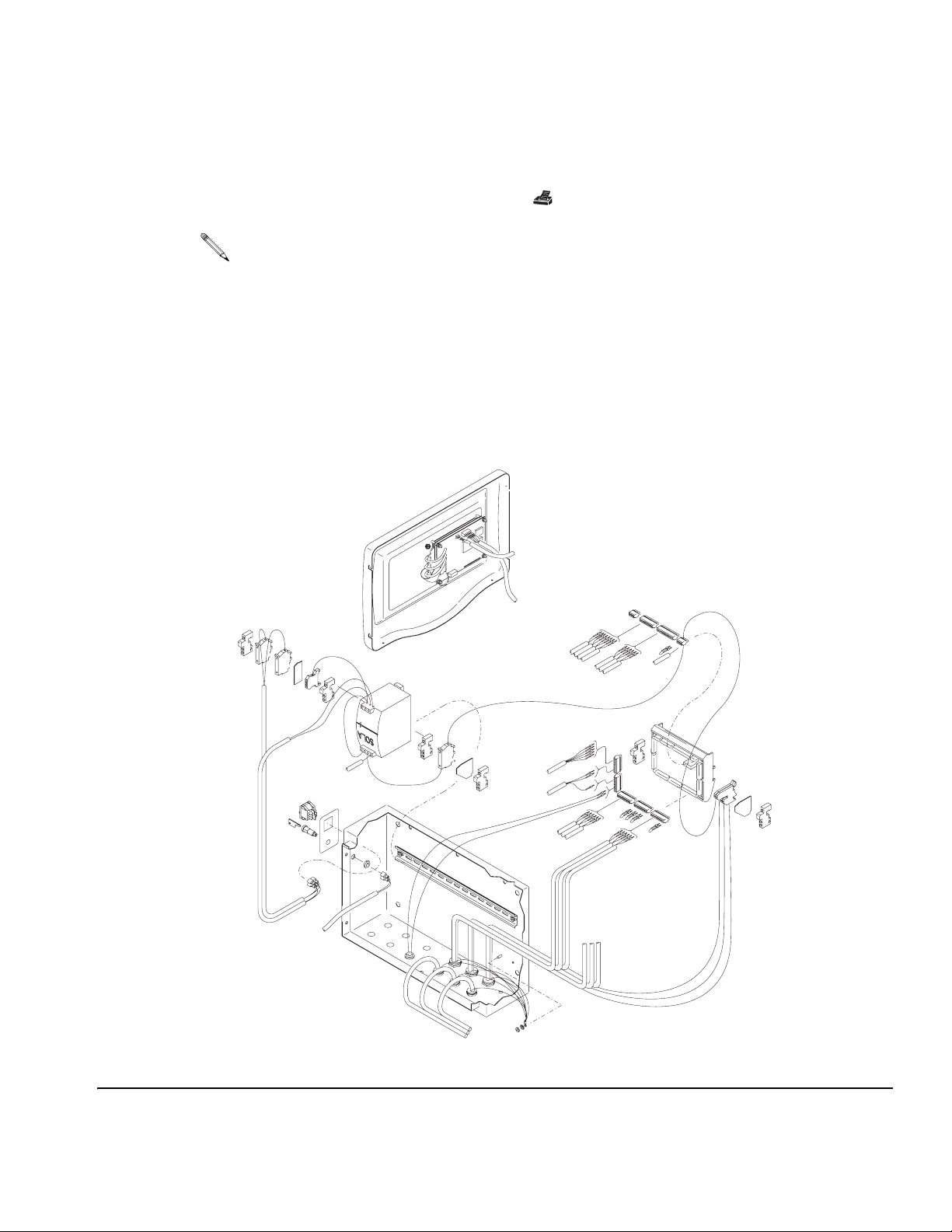
Replacing Display Board
1. Turn off controller power switch.
2. Remove controller cover (A). See page 37, steps 1-4.
3. Unplug keypad (D) ribbon cable from the display board. Note position of cable in connector. Arrow indicates pin #1, reconnect with pin #1 engaged.
4. Remove four nuts (C1) from the board. See F
IG. 15.
5. Disconnect ground wire.
6. Unplug three fiber optic connectors (C3) from the diodes, then remove display board (F).
7. Install parts in reverse order of disassembly.
• If replacing software chip, use a chip puller to remove it.
• Spacers (G) must be used in correct positions to protect the display and board.
C
F
C1
G
D
C3
A
TI1056A
FIG. 15
309301G 39
Page 40

Replacing Display
1. Follow steps 1 through 6 in the procedure for replacing the display board.
Service
2. Remove the display (C). See F
3. Install the parts in reverse order of disassembly.
• Make sure the keypad ribbon cable does not interfere with the display.
• Spacers (G) must be used in correct positions to protect the display and board.
IG. 15.
Replacing Membrane
1. Follow steps 1-6 in the procedure for replacing the display board, page 39.
2. Remove display (C). See F
3. Peel the membrane (D) off the controller cover.
4. Remove adhesive liner from the new membrane. Align the membrane with recessed area
on the panel (A), and press it into place.
5. Install parts in reverse order of disassembly.
Spacers (G) must be used in correct positions to protect the display and board.
IG. 15.
40 309301G
Page 41

Replacing Main Board
1. Turn off controller power switch.
2. Remove controller cover. See page 37, steps 1-4.
Service
3. Unplug all wire connectors (G) from the main board (H). See F
4. Squeeze release clips and pull the main board (H) away from the din rail (J).
5. Install parts in reverse order of disassembly.
If replacing software chip, use a chip puller to remove it.
IG. 16.
5
G
4
1
3
H
1
5
4
J
2
3
TI1441A
2
FIG. 16
309301G 41
Page 42

Replacing Power Supply
1. Turn off controller power switch.
2. Remove controller cover. See page 37, steps 1-4.
3. Unplug all wire connectors from the power supply.
Service
4. Pull the tab up with a screw driver and remove the power supply from the din rail. See F
17.
5. Install parts in reverse order of disassembly.
TI1455a
FIG. 17
IG.
42 309301G
Page 43

Replacing Fluid Panel Junction Box
1. Turn off controller power switch.
2. Disconnect three cables (C) from the junction box (J). See FIG. 18.
3. Remove four screws (K) and remove junction box cover (L).
4. Disconnect meter and solenoid wires (M) from the terminal block.
5. Loosen two strain relief connectors (N) to pull out the wires.
C
Service
FIG. 18
J
N
K
M
M
L
L
ti1403a
309301G 43
Page 44

FIG. 19
Service
P
M
J
ti1404a
6. Remove the two screws (P) and remove the junction box (J). See F
7. Secure the new junction box with the two screws (P).
IG. 19.
44 309301G
Page 45

Service
8. Connect meter and solenoid wires (M) to the terminal block. Connect as shown for the
specific fluid panel in F
IG. 20.
FIG. 20
9. Tighten two strain relief connectors (N). See F
IG. 18.
10. Secure the cover (L) with four screws (K).
11. Reconnect three cables (C).
309301G 45
Page 46

Service
Servicing Fluid Panel 244599
Replacing Fluid Meter or Solenoid
1. If necessary, purge ProDispense system (page 35).
2. Relieve pressure (page 24) and turn off controller power switch.
3. Follow steps 3–5 on page 43 to disconnect meter and solenoid cables from the terminal
block.
4. Disconnect fluid lines from the meter and solenoid.
5. Remove two bolts (6) and washers (7) from the solenoid (3), and remove solenoid and
meter assembly. See F
6. Place flats of the solenoid (3) in a vice and unscrew the meter (4).
IG. 21.
7. Install new meter or solenoid.
8. Secure the assembly to the fluid panel with solenoid washers (7) and bolts (6).
9. Follow steps 8–10 on page 45 to connect meter and solenoid cables to the terminal block.
10. Connect fluid lines to the meter and solenoid.
11. Load fluid at low pressure and check for leaks. Tighten fittings as needed.
46 309301G
Page 47

ti1413a
Service
4
FIG. 21
5
7
6
3
309301G 47
Page 48

Service
Servicing Fluid Panel 244600
Replacing Fluid Meter or Solenoid
1. If necessary, purge ProDispense system (page 35).
2. Relieve pressure (page 24) and turn off controller power switch.
3. Follow steps 3–5 on page 43 to disconnect meter cable from the terminal block. If replacing the solenoid, also disconnect solenoid cable.
4. If replacing meter (4):
a. Disconnect fluid line from the meter. Loosen two nuts (A) holding the meter and
remove meter. See F
b. Secure new meter (4) with the nuts (A). Continue with step 6.
IG. 22.
5. If replacing solenoid (3):
a. Disconnect fluid lines from meter and solenoid.
b. Remove two bolts (6) and washers (7) from the solenoid (3), and remove solenoid
and meter assembly. See F
c. Place flats of the solenoid (3) in a vice and unscrew the meter (4).
d. Secure new solenoid (3) to the meter with the nut (A).
e. Secure meter and solenoid assembly to the fluid panel with solenoid washers (7) and
bolts (6).
6. Follow steps 8–10 on page 45 to connect meter cable (and solenoid cable if it was disconnected) to the terminal block.
7. Connect fluid line(s).
8. Load fluid at low pressure and check for leaks. Tighten fittings as needed.
IG. 22.
48 309301G
Page 49

Service
ti1412a
A
4
A
FIG. 22
7
6
3
309301G 49
Page 50

Service
Servicing Fluid Panel 244601 and 246837
Replacing Fluid Meter, Solenoid, or Dispense Valve
1. If necessary, purge ProDispense system (page 35).
2. Relieve pressure (page 24) and turn off controller power switch.
3. Follow steps 3–5 on page 43 to disconnect meter and solenoid cables from the terminal
block.
4. Disconnect fluid lines from the meter and dispense valve. Disconnect air line from the
solenoid.
5. Remove screw (20) and washer (21) from the meter (4). Remove meter, dispense valve
and solenoid assembly from the fluid panel.
Remove fittings from old components and reinstall in new components as needed.
6. If replacing meter (4):
a. Place flats of the solenoid (3) in a vice and unscrew the meter (4).
b. Screw new meter into connector (A).
7. If replacing dispense valve (19):
a. Place flats of the solenoid (3) in a vice and unscrew the meter (4).
b. Unscrew dispense valve (19) from the solenoid (3).
c. Screw new dispense valve into connector (C).
d. Screw the meter into the connector (A).
8. If replacing solenoid (3):
a. Place flats of the solenoid (3) in a vice and unscrew dispense valve and meter
assembly.
b. Screw new solenoid (3) into connector (B).
9. Secure the assembly to the fluid panel with screw (20) and washer (21).
10. Follow steps 8–10 on page 45 to connect meter and solenoid cables to the terminal block.
11. Connect fluid lines to the meter and dispense valve. Connect air line to the solenoid.
50 309301G
Page 51

12. Load fluid at low pressure and check for leaks. Tighten fittings as needed.
21
Service
20
4
FIG. 23
ti1411a
Show meter removal
3
A
19
C
B
309301G 51
Page 52

Service
Servicing Fluid Panel 246838
Replacing Solenoid or Dispense Valve
1. If necessary, purge ProDispense system (page 35).
2. Relieve pressure (page 24) and turn off controller power switch.
3. Follow steps 3–5 on page 43 to disconnect meter and solenoid cables from the terminal
block.
4. Disconnect fluid lines from the meter and dispense valve. Disconnect air line from the
solenoid.
5. Remove dispense valve and solenoid assembly from the fluid panel.
Remove fittings from old components and reinstall in new components as needed.
6. If replacing dispense valve (19):
a. Place flats of the solenoid (3) in a vice.
b. Unscrew dispense valve (19) from the solenoid (3).
c. Screw new dispense valve into connector (C).
7. If replacing solenoid (3):
a. Place flats of the solenoid (3) in a vice and unscrew dispense valve.
b. Screw new solenoid (3) into connector (B).
8. Follow steps 8–10 on page 45 to connect meter and solenoid cables to the terminal block.
9. Connect fluid lines to the meter and dispense valve. Connect air line to the solenoid.
10. Load fluid at low pressure and check for leaks. Tighten fittings as needed.
52 309301G
Page 53

Service
FIG. 24
3
A
19
C
B
309301G 53
Page 54

Service
Servicing Fluid Panel 246839
Replacing Fluid Meter, Solenoid, or Dispense Valve
1. If necessary, purge ProDispense system (page 35).
2. Relieve pressure (page 24) and turn off controller power switch.
3. Follow steps 3–5 on page 43 to disconnect meter and solenoid cables from the terminal
block.
4. Disconnect fluid lines from the meter and dispense valve. Disconnect air line from the
solenoid.
5. Remove screw (20) and washer (21) from the meter (4). Remove meter, dispense valve
and solenoid assembly from the fluid panel.
Remove fittings from old components and reinstall in new components as needed.
6. If replacing meter (4):
a. Place flats of the solenoid (3) in a vice and unscrew the meter (4).
b. Screw new meter into connector (A).
7. If replacing dispense valve (19):
a. Place flats of the solenoid (3) in a vice and unscrew the meter (4).
b. Unscrew dispense valve (19) from the solenoid (3).
c. Screw new dispense valve into connector (C).
d. Screw the meter into the connector (A).
8. If replacing solenoid (3):
a. Place flats of the solenoid (3) in a vice and unscrew dispense valve and meter
assembly.
b. Screw new solenoid (3) into connector (B).
9. Secure the assembly to the fluid panel with screw (20) and washer (21).
10. Follow steps 8–10 on page 45 to connect meter and solenoid cables to the terminal block.
11. Connect fluid lines to the meter and dispense valve. Connect air line to the solenoid.
54 309301G
Page 55

12. Load fluid at low pressure and check for leaks. Tighten fittings as needed.
21
Service
20
4
FIG. 25
ti1411a
Show meter removal
3
A
19
C
B
309301G 55
Page 56

Wiring Charts
Service
Control Box Wiring Chart
Wire / Harness
Internal Wiring
198556
Main PCB to 7 pin
bulkhead (1A)
198556
Main PCB to 7 pin
Bulkhead (2A)
Connection
(Connector-Pin)
Fuse 1 PWR SW 1A black
Fuse 2 PWR SW 2A black
PWR SW 1 P Supply L black
PWR SW 2 P Supply N black
GND TB P Supply G green/yellow
P Supply G P Supply - green/yellow
P Supply - J7-3 blue ground
P Supply + Fuse 3 blue
Fuse 3 J7-4 blue
J7-4 J7-1 blue jumper
J7-1 terminal block red 24 VDC power
J9-9 J9-10 blue jumper
J10-1 J10-2 blue jumper
J10-2 J10-3 blue jumper
J10-3 J10-4 blue jumper
terminal block P-1 red 24 VDC power
J9-5 P-2 red stop PB
P-3 open
J9-6 P-4 black start PB
J6-2 P-5 red solenoid
J6-1 P-6 black ground
ring terminal P-7 green ground
terminal block P-1 red 24 VDC power
J9-3 P-2 red stop PB
P-3 open
J9-4 P-4 black start PB
J6-4 P-5 red solenoid
J6-3 P-6 black ground
ring terminal P-7 green ground
Color Function
56 309301G
Page 57

Control Box Wiring Chart
Service
Wire / Harness
198556
Main PCB to 7 pin
bulkhead (3A)
198557
Main PCB to 4 pin
bulkhead (1B)
198557
Main PCB to 4 pin
bulkhead (2B)
198557
Main PCB to 4 pin
bulkhead (3B)
116726
Main PCB to 3 pin
bulkhead
197827
Main board to
front panel
197835
Front panel to
key switch
Connection
(Connector-Pin)
terminal block P-1 red 24 VDC power
J9-1 P-2 red stop PB
P-3 open
J9-2 P-4 black start PB
J6-6 P-5 red solenoid
J6-5 P-6 black ground
ring terminal P-7 green ground
J11-7 P-1 red 24 VDC power
J11-8 P-2 black ground
J11-9 P-3 clear meter signal
ring terminal P-4 drain ground
J11-4 P-1 red 24 VDC power
J11-5 P-2 black ground
J11-6 P-3 clear meter signal
ring terminal P-4 drain ground
J11-1 P-1 red 24 VDC power
J11-2 P-2 black ground
J11-3 P-3 clear meter signal
ring terminal P-4 drain ground
J2-6 P-1 black ground
J2-7 P-2 clear printer
P-3 shield
J3-1 J4-1 brown RS485_B
J3-2 J4-2 white RS485_A
J3-3 J4-5 black ground
J3-5 J4-3 green DSRI
J3-10 J4-4 red VCC
J1-1 SW1 black key switch
J1-2 SW2 red key switch
Color Function
309301G 57
Page 58

Fluid Panel Wiring Chart
Service
Harness
198426
Control box to fluid
panel (1A, 2A, 3A)
198427
Control box to fluid
panel (1B, 2B, 3B)
116669
Remote operator
station
Connection
(Connector-Pin)
Pin-1 Pin-1 orange
Pin-2 Pin-2 white
Pin-3 Pin-3 green
Pin-4 Pin-4 blue
Pin-5 Pin-5 black
Pin-6 Pin-6 red
Pin-7 Pin-7 shield
Pin-1 Pin-1 red
Pin-2 Pin-2 black
Pin-3 Pin-3 white
Pin-4 Pin-4 shield
F1 2POS SW NC 2 orange
F2 2POS SW NO 3 orange
F3 Start PB X1 orange
F4 Start PB NO 4 brown
F5 2POS SW NO 4 brown
F6 Stop PB NC 1 brown/green
F7 Start PB NO 3 white
F8 Start PB X2 black/green
F9 Ground Lug green
F10 Stop PB NC 2 red
F11 Stop PB NC 1 blue
F12 Ground Lug shield
stop PB NC 2 2POS SW NC 1 blue jumper
Color Function
58 309301G
Page 59

Fluid Panel Wiring Chart
Service
Harness
244660
Fluid panel
junction box
Terminal block 5 & 6
are bridged
Terminal block 7 & 8
are bridged
Used for 244599,
244600, 244601
fluid panels
244599
Fluid panel (oil)
244600
Fluid panel (water)
246837
246839
244601
Fluid panel (grease)
Connection
(Connector-Pin)
T Block 1 Pin-1 orange
T Block 2 Pin-2 white
T Block 3 Pin-5 black
T Block 4 Pin-4 blue
T Block 7 Pin-6 red
ground Pin-7 green/yellow
T Block 1 Pin-1 orange
T Block 2 Pin-2 white
T Block 3 Pin-6 red
T Block 4 Pin-4 blue
T Block 5 Pin-5 black
ring terminal Pin-7 green/yellow
T Block 9 Pin-1 red
T Block 10 Jumper
T Block 11 Pin-2 black
T Block 12 Pin-3 white
T Block 13 Pin-4 G/Y & shield
TB 10 red
TB 12 white
TB 6 black
TB 8 black
TB 10 brown
TB 12 green
TB 6 black
TB 8 black
TB 10 red
TB 11 black
TB 12 white
TB13 green/shield
TB 6 black
TB 8 black
Color Function
197573
6 pin bulkhead
operator station
197574
7 pin bulkhead (A)
cable connection
197575
4 pin bulkhead (B)
cable connection
meter wiresTB 11 black
solenoid wires
meter wiresTB 11 white
solenoid wires
meter wires
solenoid wires
309301G 59
Page 60

Fluid Panel Wiring Chart
Service
Harness
246838
Fluid Panel
(Grease)
Harness
197458
(5 ft., 1.52 m)
198669
(50 ft. 15.24 m)
Printer Cable
Connection
(Connector-Pin)
TB 6 black
TB 8 black
Color Function
Accessories Wiring Chart
Connection
(Connector-Pin)
2 1 shield
3 3 clear
15black
4
6
Color Function
jumper
Field Wiring Chart - Output
solenoid wires
Harness
Connection
(Connector-Pin)
J5-1 ground
J5-2 General Alarm (24 VDC)
J5-3 ground
J5-4 Fluid 1 Alarm (24 VDC)
J5-5 ground
J5-6 Fluid 2 Alarm (24 VDC)
J5-7 ground
J5-8 Fluid 3 Alarm (24 VDC)
J3-8 Modbus B
J3-9 Modbus A
J2-6 ground
Color Function
60 309301G
Page 61

Notes:
Service
309301G 61
Page 62

Parts
Part No. 244561, Controller
32
Parts
E
48
46
D
4a
12
31
33
5
A
3
24
C
D
B
4
E
16
20
B
C
49
A
47
19
TI1462A
50
Ref. # Part # Description Qty.
3 197386 LABEL, power switch 1
4 116368 SWITCH, key, 2-position, includes item 4a 1
4a 116370 • KEY PACKAGE (2 duplicate keys) 1
5 116320 SWITCH, power 1
12 196975 POWER SUPPLY, 24 VDC 1
13 244952 BOARD, circuit, main control 1
16 197835 HARNESS, wire 1
18 245222 COVER ASSEMBLY, electrical section, includes items 18a-18h 1
18a 197431 • COVER, enclosure 1
18b 116371 • SPACER, 0.151” ID 4
18c 197281 • SWITCH, membrane 1
18d 198573 • DISPLAY, graphic 1
13
62 309301G
Page 63

Ref. # Part # Description Qty.
18e 116374 • SPACER, 0.14” ID 4
18f 244407 • BOARD, circuit, display 1
18g 103181 • WASHER, lock, external, #6 4
18h 100072 • NUT, hex, 6-32 UNC-2B 4
19 198556 WIRE HARNESS, solenoid 3
20 198557 WIRE HARNESS, meter 3
22 194741 LABEL, warning (not shown) 1
24 116726 WIRE HARNESS, printer 1
31 114835 FUSE, time lag, 4 A, 250 V 1
32 120614 FUSE, time lag, 1.6 A, 250 V 2
33 197827 WIRE HARNESS 1
46 116772 CONNECTOR, plug, 3.81 mm, 4 position 1
47 116773 CONNECTOR, plug, 3.81 mm, 10 position 3
48 116774 CONNECTOR, plug, 3.81 mm, 13 position 1
49 116343 SCREW, ground 1
50 222011 CLAMP, grounding 1
Parts
Item 18 Cover Assembly
Part No. 245222
18f
18d
18h
18g
18e
18b
18a
TI1056A
18c
309301G 63
Page 64

Part No. 244599, Fluid Panel
Parts
21
9, 10, 11, 12, 20
54
22
14, 15
23
1
ti1323a
26, 7
Ref. # Part # Description Qty.
1 116421 PANEL, fluid dispense 1
2 197576 BLOCK, solenoid mount 1
3 110025 VALVE, solenoid 1
4 238618 METER, electronic pulse, see Manual 308245 for parts 1
5 158491 FITTING, nipple, 1/2-14 npt 1
6 102313 SCREW, cap, 1/4-20 UNC-2A x 1.75” 2
7 110755 WASHER, plain, 0.281” ID 6
8 102040 NUT, lock, hex, 1/4-20 UNC-3B 2
9 104029 CLAMP, ground 1
10 104582 WASHER, tab, 5.3 mm ID 1
11 100718 WASHER, lock, #10 1
12 105332 NUT, lock, hex, M5 x 0.8 1
13 244660 JUNCTION BOX, electrical 1
14 101577 SCREW, cap, hex hd., 10-24 UNC-2A x 0.375” 2
15 C38163 WASHER, lock, star, #10 2
16 100021 SCREW, cap, hex hd., 1/4-20 UNC-2A x 1” 2
17 112514 FERRULE, wire, AWG 18 (not shown) 2
18 112512 FERRULE, wire, AWG 26-22 (not shown) 3
20 237569 WIRE ASSY., 25 ft. (7.6 m) 1
21 116669 OPERATOR STATION, remote 1
22 198426 HARNESS, wire 1
23 198427 HARNESS, wire 1
13
3
7, 8, 16
64 309301G
Page 65

Part No. 244600, Fluid Panel
Parts
21
9, 10, 11, 12
4
6, 7
, 20
22
14, 15
23
1
13
7, 8, 16
3
ti1322a
2
Ref. # Part # Description Qty.
1 116421 PANEL, fluid dispense 1
2 197576 BLOCK, solenoid mount 1
3 110025 VALVE, solenoid 1
4 513891 METER, pulse, water 1
6 102313 SCREW, cap, 1/4-20 UNC-2A x 1.75” 2
7 110755 WASHER, plain, 0.281” ID 6
8 102040 NUT, lock, hex, 1/4-20 UNC-3B 2
9 104029 CLAMP, ground 1
10 104582 WASHER, tab, 5.3 mm ID 1
11 100718 WASHER, lock, #10 1
12 105332 NUT, lock, hex, M5 x 0.8 1
13 244660 JUNCTION BOX, electrical 1
14 101577 SCREW, cap, hex hd., 10-24 UNC-2A x 0.375” 2
15 C38163 WASHER, lock, star, #10 2
16 100021 SCREW, cap, hex hd., 1/4-20 UNC-2A x 1” 2
17 112514 FERRULE, wire, AWG 18 (not shown) 2
18 112512 FERRULE, wire, AWG 26-22 (not shown) 3
20 237569 WIRE ASSY., 25 ft. (7.6 m) 1
21 116669 OPERATOR STATION, remote 1
22 198426 HARNESS, wire 1
23 198427 HARNESS, wire 1
309301G 65
Page 66

Part No. 244601, Fluid Panel
9, 10, 11, 12, 25
Parts
26
20, 21
4
2
27
14, 15
28
13
ti1324b
3
Ref. # Part # Description Qty.
1 116421 PANEL, fluid dispense 1
2 156971 NIPPLE, short, 1/4-18 npt 1
3 116463 VALVE, solenoid 1
4 239716 METER, gear, G3000, see Manual 308778 for parts 1
6 112173 MUFFLER, 1/4-18 npt 1
7 181256 NEEDLE, fluid 1
8 110249 ADAPTER, male, 90° elbow, 1/4-18 npt 1
9 104029 CLAMP, ground 1
10 104582 WASHER, tab, 5.3 mm ID 1
11 100718 WASHER, lock, #10 1
12 105332 NUT, lock, hex, M5 x 0.8 1
13 244660 JUNCTION BOX, electrical 1
14 101577 SCREW, cap, hex hd., 10-24 UNC-2A x 0.375” 2
15 C38163 WASHER, lock, star, #10 2
16 156823 UNION, swivel, 1/4-18 npt 2
17 112514 FERRULE, wire, AWG 18 (not shown) 2
18 112512 FERRULE, wire, AWG 26-22 (not shown) 3
19 205612 VALVE, dispense, automatic, see Manual 306715 for parts 1
20 105468 SCREW, cap, hex hd., M6 x 12 2
21 110755 WASHER, 0.281” ID 2
22 244661 CABLE, G3000 meter (not shown) 1
23 164749 TIP, valve 1
24 164111 WASHER, 0.465” ID 1
25 237569 WIRE ASSY., 25 ft. (7.6 m) 1
26 116669 OPERATOR STATION, remote 1
27 198426 HARNESS, wire 1
28 198427 HARNESS, wire 1
1
7, 19, 23, 24
8
16
6
66 309301G
Page 67

Part No. 246837, Fluid Panel
9, 10, 11, 12, 25
Parts
26
20, 21
4
2
27
14, 15
28
13
ti1324a
3
Ref. # Part # Description Qty.
1 116421 PANEL, fluid dispense 1
2 156971 NIPPLE, short, 1/4-18 npt 1
3 116463 VALVE, solenoid 1
4 244292 METER, gear, G3000 HR, see Manual 308778 for parts 1
6 112173 MUFFLER, 1/4-18 npt 1
7 181256 NEEDLE, fluid 1
8 110249 ADAPTER, male, 90° elbow, 1/4-18 npt 1
9 104029 CLAMP, ground 1
10 104582 WASHER, tab, 5.3 mm ID 1
11 100718 WASHER, lock, #10 1
12 105332 NUT, lock, hex, M5 x 0.8 1
13 244660 JUNCTION BOX, electrical 1
14 101577 SCREW, cap, hex hd., 10-24 UNC-2A x 0.375” 2
15 C38163 WASHER, lock, star, #10 2
16 156823 UNION, swivel, 1/4-18 npt 2
17 112514 FERRULE, wire, AWG 18 (not shown) 2
18 112512 FERRULE, wire, AWG 26-22 (not shown) 3
19 205612 VALVE, dispense, automatic, see Manual 306715 for parts 1
20 105468 SCREW, cap, hex hd., M6 x 12 2
21 110755 WASHER, 0.281” ID 2
22 244661 CABLE, G3000 meter (not shown) 1
23 164749 TIP, valve 1
24 164111 WASHER, 0.465” ID 1
25 237569 WIRE ASSY., 25 ft. (7.6 m) 1
26 116669 OPERATOR STATION, remote 1
27 198426 HARNESS, wire 1
28 198427 HARNESS, wire 1
1
7, 19, 23, 24
8
16
6
309301G 67
Page 68

Part No. 246838, Fluid Panel
9, 10, 11, 12, 25
Parts
26
27
14, 15
28
13
ti1324a
3
Ref. # Part # Description Qty.
1 116421 PANEL, fluid dispense 1
3 116463 VALVE, solenoid 1
6 112173 MUFFLER, 1/4-18 npt 1
7 181256 NEEDLE, fluid 1
8 110249 ADAPTER, male, 90° elbow, 1/4-18 npt 1
9 104029 CLAMP, ground 1
10 104582 WASHER, tab, 5.3 mm ID 1
11 100718 WASHER, lock, #10 1
12 105332 NUT, lock, hex, M5 x 0.8 1
13 244660 JUNCTION BOX, electrical 1
14 101577 SCREW, cap, hex hd., 10-24 UNC-2A x 0.375” 2
15 C38163 WASHER, lock, star, #10 2
16 156823 UNION, swivel, 1/4-18 npt 2
17 112514 FERRULE, wire, AWG 18 (not shown) 2
18 112512 FERRULE, wire, AWG 26-22 (not shown) 3
19 205612 VALVE, dispense, automatic, see Manual 306715 for parts 1
22 244661 CABLE, G3000 meter (not shown) 1
23 164749 TIP, valve 1
24 164111 WASHER, 0.465” ID 1
25 237569 WIRE ASSY., 25 ft. (7.6 m) 1
26 116669 OPERATOR STATION, remote 1
27 198426 HARNESS, wire 1
28 198427 HARNESS, wire 1
1
7, 19, 23, 24
8
16
6
68 309301G
Page 69

Part No. 246839, Fluid Panel
9, 10, 11, 12, 25
Parts
26
20, 21
30, 31
32
29
4
27
14, 15
28
13
1
3
2
Ref. # Part # Description Qty.
1 116421 PANEL, fluid dispense 1
2 15B556 NIPPLE, short, 1/4-18 npt 1
3 116463 VALVE, solenoid 1
4 246190 METER, heli gear, amb with sensor (see manual 309834 for parts) 1
6 112173 MUFFLER, 1/4-18 npt 1
7 181256 NEEDLE, fluid 1
8 110249 ADAPTER, male, 90° elbow, 1/4-18 npt 1
9 104029 CLAMP, ground 1
10 104582 WASHER, tab, 5.3 mm ID 1
11 100718 WASHER, lock, #10 1
12 105332 NUT, lock, hex, M5 x 0.8 1
13 244660 JUNCTION BOX, electrical 1
14 101577 SCREW, cap, hex hd., 10-24 UNC-2A x 0.375” 2
15 C38163 WASHER, lock, star, #10 2
16 156823 UNION, swivel, 1/4-18 npt 2
17 112514 FERRULE, wire, AWG 18 (not shown) 2
18 112512 FERRULE, wire, AWG 26-22 (not shown) 3
19 205612 VALVE, dispense, automatic, see Manual 306715 for parts 1
20 117028 SCREW, cap, hex hd., M6 x 16 2
21 115226 WASHER, M6 2
22 198578 CABLE, G3000 meter (not shown) 1
23 164749 TIP, valve 1
24 164111 WASHER, 0.465” ID 1
25 237569 WIRE ASSY., 25 ft. (7.6 m) 1
26 116669 OPERATOR STATION, remote 1
27 198426 HARNESS, wire 1
28 198427 HARNESS, wire 1
29 193715 FITTING, union, swivel 1
7, 19, 23, 24
8
16
6
309301G 69
Page 70

Notes
Notes
70 309301G
Page 71

Technical Data
Power Requirements
Electrical . . . . . . . . . . . . . . . . . . . . 115/230 VAC, 1.6 amp maximum,
Pneumatic . . . . . . . . . . . . . . . . . . .
(Model 244601 only)
Number of fluids . . . . . . . . . . . . . . . . . .
Totalizers . . . . . . . . . . . . . . . . . . . . . . . .
No. of Recipes. . . . . . . . . . . . . . . . . . . .
Cable Lengths
Meter Signal. . . . . . . . . . . . . . . . . . . 50 ft. (15.24 m)
Solenoid signal. . . . . . . . . . . . . . . . . 50 ft. (15.24 m)
Operator Station. . . . . . . . . . . . . . . . 10 ft. (3.05 m)
Fluid Panels
244599 Oil /Lubricant
Flow rate . . . . . . . . . . . . . . . . . . . . . 0.25-4 gpm (0.95-15 lpm)
Viscosity range. . . . . . . . . . . . . . . . . 10 wt. oil - #2 grease
Accuracy . . . . . . . . . . . . . . . . . . . . . +
Resolution . . . . . . . . . . . . . . . . . . . . 4.73 cc/pulse
Maximum Working Pressure . . . . . . 1500 psi (10 MPa, 103 bar)
Fluid inlet . . . . . . . . . . . . . . . . . . . . . 1/2 npt(f)
Fluid outlet . . . . . . . . . . . . . . . . . . . . 1/2 npt(f)
244600 Water/Antifreeze
Flow rate . . . . . . . . . . . . . . . . . . . . . 0.25-4 gpm (0.95-15 lpm)
Viscosity range. . . . . . . . . . . . . . . . . 1-20 cps
Accuracy . . . . . . . . . . . . . . . . . . . . . +
Resolution . . . . . . . . . . . . . . . . . . . . 25 cc/pulse
Maximum Working Pressure . . . . . . 250 psi (1.7 MPa, 17 bar)
Fluid inlet . . . . . . . . . . . . . . . . . . . . . 1/2 npt(m)
Fluid outlet . . . . . . . . . . . . . . . . . . . . 1/2 npt(f)
244601 Grease/Paint
Flow rate . . . . . . . . . . . . . . . . . . . . . 0.2-1 gpm (0.76-3.8 lpm)
Viscosity range. . . . . . . . . . . . . . . . . 20-5000 cps
Accuracy . . . . . . . . . . . . . . . . . . . . . +
Resolution . . . . . . . . . . . . . . . . . . . . 0.119 cc/pulse
Maximum Working Pressure . . . . . . 3000 psi (21 MPa, 207 bar)
Maximum Air Pressure. . . . . . . . . . . 120 psi (0.8 MPa, 8 bar)
Fluid inlet . . . . . . . . . . . . . . . . . . . . . 1/4 npt(f)
Fluid outlet . . . . . . . . . . . . . . . . . . . . 3/8 npt(m)
Air inlet . . . . . . . . . . . . . . . . . . . . . . . 1/4 npt(f)
Technical Data
50 or 60 Hz
85-120 psi (0.59-0.9 MPa, 5.9-9 bar) at 1/4 cfm
maximum (filtered to 10 micron)
1-3 valves
Last dispense
Resettable
Grand
250 maximum
20 ft. (6.10 m) available
1/2% on dispenses over one gallon
3% on dispenses over one gallon
3% on dispenses over 12 cc
309301G 71
Page 72

246837 Grease/Paint
Flow rate . . . . . . . . . . . . . . . . . . . . . .01-.5 gpm (.038-1.9 lpm)
Viscosity range . . . . . . . . . . . . . . . . 20-3000 cps
Accuracy . . . . . . . . . . . . . . . . . . . . . +
Resolution . . . . . . . . . . . . . . . . . . . . .061 cc/pulse
Maximum Working Pressure. . . . . . 3000 psi ( 21 MPa, 207 bar)
Maximum Air Pressure . . . . . . . . . . 120 psi (0.8 MPa, 8 bar)
Fluid inlet. . . . . . . . . . . . . . . . . . . . . 1/4 npt(f)
Fluid outlet . . . . . . . . . . . . . . . . . . . 3/8 npt(f)
Air inlet . . . . . . . . . . . . . . . . . . . . . . 1/4 npt(f)
246838 Meter-less
(flow meter supplied by user)
Flow rate . . . . . . . . . . . . . . . . . . . . . (TBD) User supplied
Viscosity range . . . . . . . . . . . . . . . . (TBD) User supplied
Accuracy . . . . . . . . . . . . . . . . . . . . . (TBD) User supplied
Resolution . . . . . . . . . . . . . . . . . . . . (TBD) User supplied
Maximum Working Pressure. . . . . . 3000 psi (21 MPa, 207bar)
Maximum Air Pressure . . . . . . . . . . 120 psi (0.8 MPa, 8 bar)
Fluid inlet. . . . . . . . . . . . . . . . . . . . . (TBD) User supplied
Fluid outlet . . . . . . . . . . . . . . . . . . . 1/4 npt(f)
Air inlet . . . . . . . . . . . . . . . . . . . . . . 1/4 npt(f)
246839 Grease/Paint/Sealants
Flow rate . . . . . . . . . . . . . . . . . . . . . .013-6 gpm (.05-22 lpm)
Viscosity range . . . . . . . . . . . . . . . . 30-1,000,000 cps
Accuracy . . . . . . . . . . . . . . . . . . . . . +
Resolution . . . . . . . . . . . . . . . . . . . . 0.286 cc/pulse
Maximum Working Pressure. . . . . . 3000 psi (21 MPa, 207 bar)
Maximum Air Pressure . . . . . . . . . . 120 psi (0.8 MPa, 8 bar)
Fluid inlet. . . . . . . . . . . . . . . . . . . . . 3/4 npt(f)
Fluid outlet . . . . . . . . . . . . . . . . . . . 3/8 npt(m)
Air inlet . . . . . . . . . . . . . . . . . . . . . . 1/4 npt(f)
Technical Data
1.5% on dispenses over 12 cc
5% on dispenses over 12 cc
72 309301G
Page 73

Wetted Parts
244599 . . . . . . . . . . . . . . . . . . . . . . . aluminum, carbon steel, bronze, buna-N,
stainless steel
244600 . . . . . . . . . . . . . . . . . . . . . . . brass, stainless steel, polyimide,
polypropylene, EPDM o-ring, aluminum,
buna-N, carbon steel
244601 . . . . . . . . . . . . . . . . . . . . . . . 303, 400 series, and 416 stainless steel,
Tungsten carbide, PTFE, carbon steel,
chrome, nylon, UHMWPE, leather
ProDispense™ and EasyKey™ are trademarks of Graco Inc.
Accessories and Kits
Part Number Description
239873 Printer kit
Accessories and Kits
514037 Printer paper roll
198669 Printer cable
50 ft. (15.24 m)
197902 Paint Shield
For display screen, package of 10
198456 Remote Station Extension Cable
20 ft. (6.1 m)
245248 Software Upgrade Kit for Main PCB
Includes main PCB chip with software upgrade, chip extractor, and grounding strap.
244840 Software Upgrade Kit for Display PCB
Includes display PCB chip, chip extractor, and grounding strap.
309301G 73
Page 74

Graco Standard Warranty
Graco warrants all equipment manufactured by Graco and bearing its name to be free from defects in material and workmanship
on the date of sale to the original purchaser for use. With the exception of any special, extended, or limited warranty published by
Graco, Graco will, for a period of twelve months from the date of sale, repair or replace any part of the equipment determined by
Graco to be defective. This warranty applies only when the equipment is installed, operated and maintained in accordance with
Graco's written recommendations.
This warranty does not cover, and Graco shall not be liable for general wear and tear, or any malfunction, damage or wear caused
by faulty installation, misapplication, abrasion, corrosion, inadequate or improper maintenance, negligence, accident, tampering,
or substitution of non-Graco component parts. Nor shall Graco be liable for malfunction, damage or wear caused by the
incompatibility of Graco equipment with structures, accessories, equipment or materials not supplied by Graco, or the improper
design, manufacture, installation, operation or maintenance of structures, accessories, equipment or materials not supplied by
Graco.
This warranty is conditioned upon the prepaid return of the equipment claimed to be defective to an authorized Graco distributor
for verification of the claimed defect. If the claimed defect is verified, Graco will repair or replace free of charge any defective
parts. The equipment will be returned to the original purchaser transportation prepaid. If inspection of the equipment does not
disclose any defect in material or workmanship, repairs will be made at a reasonable charge, which charges may include the costs
of parts, labor, and transportation.
THIS WARRANTY IS EXCLUSIVE, AND IS IN LIEU OF ANY OTHER WARRANTIES, EXPRESS OR IMPLIED, INCLUDING BUT
NOT LIMITED TO WARRANTY OF MERCHANTABILITY OR WARRANTY OF FITNESS FOR A PARTICULAR PURPOSE.
Graco's sole obligation and buyer's sole remedy for any breach of warranty shall be as set forth above. The buyer agrees that no
other remedy (including, but not limited to, incidental or consequential damages for lost profits, lost sales, injury to person or
property, or any other incidental or consequential loss) shall be available. Any action for breach of warranty must be brought
within two (2) years of the date of sale.
Graco makes no warranty, and disclaims all implied warranties of merchantability and fitness for a particular purpose in
connection with accessories, equipment, materials or components sold but not manufactured by Graco. These items sold, but not
manufactured by Graco (such as electric motors, switches, hose, etc.), are subject to the warranty, if any, of their manufacturer.
Graco will provide purchaser with reasonable assistance in making any claim for breach of these warranties.
In no event will Graco be liable for indirect, incidental, special or consequential damages resulting from Graco supplying
equipment hereunder, or the furnishing, performance, or use of any products or other goods sold hereto, whether due to a breach
of contract, breach of warranty, the negligence of Graco, or otherwise.
FOR GRACO CANADA CUSTOMERS
The parties acknowledge that they have required that the present document, as well as all documents, notices and legal
proceedings entered into, given or instituted pursuant hereto or relating directly or indirectly hereto, be drawn up in English. Les
parties reconnaissent avoir convenu que la rédaction du présente document sera en Anglais, ainsi que tous documents, avis et
procédures judiciaires exécutés, donnés ou intentés à la suite de ou en rapport, directement ou indirectement, avec les
procedures concernées.
Graco Information
For the latest information about Graco products, visit www.graco.com.
TO PLACE AN ORDER, contact your Graco distributor, or call to identify the nearest distributor:
1-800-328-0211 Toll Free, 612-623-6921, 612-378-3505 Fax
All written and visual data contained in this document reflects the latest product information available at the time of publication.
Graco reserves the right to make changes at any time without notice.
This manual contains English. MM 309301
Graco Headquarters: Minneapolis
International Offices: Belgium, China, Japan, Korea
GRACO INC. P.O. BOX 1441 MINNEAPOLIS, MN 55440-1441
Copyright 2001, Graco Inc. is registered to ISO 9001
www.graco.com
Revised 11/2009
 Loading...