

Page 1
INSTRUCTIONS–P
This manual contains important
warnings and information.
READ AND RETAIN FOR REFERENCE
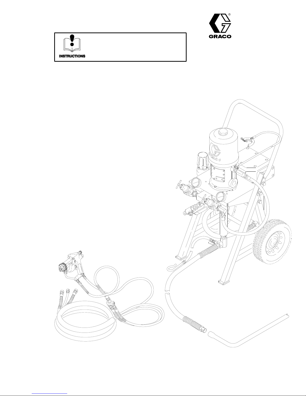
30:1 PRESIDENT, CARBON STEEL, CART MOUNTED
ARTS LIST
308–462
Rev.
B
Supersedes A
Heated
See the Data Sheet, 305–665, for application information
3000 psi (210 bar) Maximum System Working Pressure
100 psi (6.9 bar) Maximum Air Inlet Pressure
Model 237–423, Series A
This
complete package includes a pump,
an air-assisted airless–spray gun with size a 41
a portable cart, 25 ft. (7.6 m) air and fluid hoses,
air and fluid controls, and a fluid feed.
This manual provides the basic safety
operation information for the spray system. For your
safety
, also read the component manuals supplied with
this system before operating it.
A
ir-Assiste
IMPORTANT
1 spray tip,
, installation and
d A
irles
s P
ackage
GRACO INC. P.O. BOX 1441
COPYRIGHT
MINNEAPOLIS, MN
1994, GRACO INC.
04129
55440–1441
Page 2

Table
of Contents
Symbols
Symbols 2.
Warnings 3
Setup 5
System
Operation 9
Parts 14
Technical
Warranty 16
Graco
. . . . . . . . . . . . . . . . . . . . . . . . . . . . . . . . . . . . .
. . . . . . . . . . . . . . . . . . . . . . . . . . . . . . . . . . . . . .
. . . . . . . . . . . . . . . . . . . . . . . . . . . . . . . . . . . . . . . . .
Component Information7. . . . . . . . . . . . . . . . . .
. . . . . . . . . . . . . . . . . . . . . . . . . . . . . . . . . . . . .
. . . . . . . . . . . . . . . . . . . . . . . . . . . . . . . . . . . . . . . .
Data
Phone Numbers
. . . . . . . . . . . . . . . . . . . . . . . . . . . . . . .
. . . . . . . . . . . . . . . . . . . . . . . . . . . . . . . . . . . . .
. . . . . . . . . . . . . . . . . . . . . . . .
16.
16.
Warning Symbol
WARNING
This
symbol alerts you to the possibility of serious
injury or death if you do not follow the instructions.
Caution Symbol
CAUTION
This
symbol alerts you to the possibility of damage to
or destruction of equipment if you do not follow the
corresponding instructions.
Page 3
WARNINGWARNING
SKIN INJECTION HAZARD
Spray
from the gun, hose leaks or ruptured components can inject fluid into your body and cause
extremely serious injury
can also cause can also cause serious injury
D
Fluid injected into the skin is a serious injury
iuos injury
D
Do not point the spray gun at anyone or any part of the body
D
Do not put hand or fingers over the spray tip.
D
Do not stop or deflect fluid leaks with your hand, body
D
Do not “blow back” fluid; this is not an air spray system.
D
Always have the tip guard and the trigger guard on the spray gun when spraying.
D
Check the gun dif
D
Be sure the gun trigger safety operates before spraying the gun.
D
Lock the gun trigger safety when you stop spraying.
D
Follow the
checking or servicing the equipment.
. Get immediate medical attention.
Pressure relief procedure
, including the need for amputation. Splashing fluid in the eyes or on the skin
.
. The injury might look like just a cut, but it is a ser
.
, glove or rag.
fuser operation weekly
. Refer to the gun manual.
on page 9 if the spray tip clogs and before cleaning,
-
D T
ighten all fluid connections before each use.
D
Check the hoses, tubes and couplings daily
manently coupled hoses cannot be repaired.
D
Handle and route hoses and tubes carefully. Keep hoses and tubes away from moving parts and
hot surfaces. Do not use the hoses to pull equipment. Do not expose Graco hoses to tempera
tures above 180
_F (82_
C) or below –40
. Replace worn or damaged parts immediately
_F (–40_C).
TOXIC FLUID HAZARD
Improper
even death, due to splashing in the eyes, ingestion, or bodily contamination.
D
D
D W
handling of hazardous fluids or inhaling toxic fumes can cause extremely serious injury
Know the specific hazards of the fluid you are using.
Store hazardous fluid in an approved container
state and national guidelines.
ear appropriate clothing, gloves, eyewear and respirator
. Dispose hazardous fluid according to all local,
.
FLUID HEATER HAZARD
D The
heater is not appropriate for use in certain hazardous locations when soft wired as of
this package. The heater is CSA certified and FM Approved as explosion proof for Class I, Divi
sion 1, Group D, Hazardous Locations, T
manual, 307–805, for additional information.
emp Code (identification number) T3. Read the heater
. Per
-
-
,
fered in
-
D
Do not touch the heater during operation, it is very hot.
Page 4
WARNINGWARNING
FIRE AND EXPLOSION HAZARD
Improper
and result in a fire or explosion and serious injury
D
D
D
D
D
D
D
D
D
grounding, poor air ventilation, open flames or sparks can cause a hazardous condition
.
Ground the equipment and the object being sprayed. See
If there is any static sparking while using the equipment,
and correct the problem.
Provide fresh air ventilation to avoid the buildup of flammable vapors from solvent or the fluid be
ing sprayed.
Do not smoke in the spray area.
Extinguish all open flames or pilot lights in the spray area.
Do not turn on or of
Electrically disconnect all equipment in the spray area.
Keep the spray area free of debris, including solvent, rags and gasoline.
Do not operate a gasoline engine in the spray area.
f any light switch in the spray area.
Ground the system
stop spraying immediately
on 6.
. Identify
EQUIPMENT MISUSE HAZARD
Equipment
in serious injury
D
This equipment is for professional use only
misuse can cause the equipment to rupture, malfunction or start unexpectedly and result
.
.
-
Read all instruction manuals, tags, and labels before operating the equipment.
D
D
Use the equipment only for its intended purpose. If you are in doubt about this, call Graco T
cal Assistance at 1–800–543–0339.
D
Do not alter or modify this equipment. Use only genuine Graco parts and accessories.
D
Check equipment daily
D
Do not exceed the
mum incoming air pressure
used with it.
D
Do not move or lift pressurized equipment.
D Use
D
D
fluids or solvents which are compatible with equipment
section
Fluid hoses must have spring guards on both ends to protect it from rupture caused by kinks or
bends at or close to the couplings.
Comply with all applicable local, state and national fire, electrical and other safety regulations.
of all equipment manuals. Read the fluid and solvent manufacturer’s warnings.
. Repair or replace worn or damaged parts immediately
2760 psi (190 bar) maximum working pressure at 120 psi (8.3 bar) maxi
of the pump, or the maximum working pressure of any accessory
wetted parts. Refer to the Technical Data
.
MOVING PARTS HAZARD
Moving
amputate fingers.
parts, such as the air motor piston located behind the air motor plates, which can pinch or
echni-
-
D
Never operate the equipment with the air motor plates removed.
D
Keep clear of any moving parts when starting or operating the equipment.
Page 5
Setup
I. Prepare the operator.
All
persons who operate the system should be trained
in the safe, efficient operation of all system compo
nents as well as the proper handling of the chemical
coating. At a minimum, all operators should
thoroughly read the safety
, installation and operation
sections of this manual and the component manuals.
II. Prepare the site.
1. Use
2.
3.
a minimum recommended 5 HP (3.7 kW)
compressor for ef
ficient operation.
Clear obstacles and debris that could hinder the
operator’
s movement.
Bring an air line from your compressed air supply
to the pump location. Be sure the air is dry and
filtered. Install a bleed–type master air valve (A)
upstream from the pump. Another master air valve
(32) is supplied with the package. When the
bleed–type master air valve is closed and the
pump air regulator (31a) is opened, the valve
relieves all air pressure to the system.
-
air
4.
Have a grounded waste pail available to use when
draining the fluid filter
5. V
entilate the spray booth.
.
WARNING
T
o prevent hazardous concentrations of
toxic and/or flammable vapors, spray
only in a properly ventilated spray
booth.
Never operate the spray gun
unless ventilation fans are operating.
Check and follow all of the national, state and local
codes
regarding air exhaust velocity requirements.
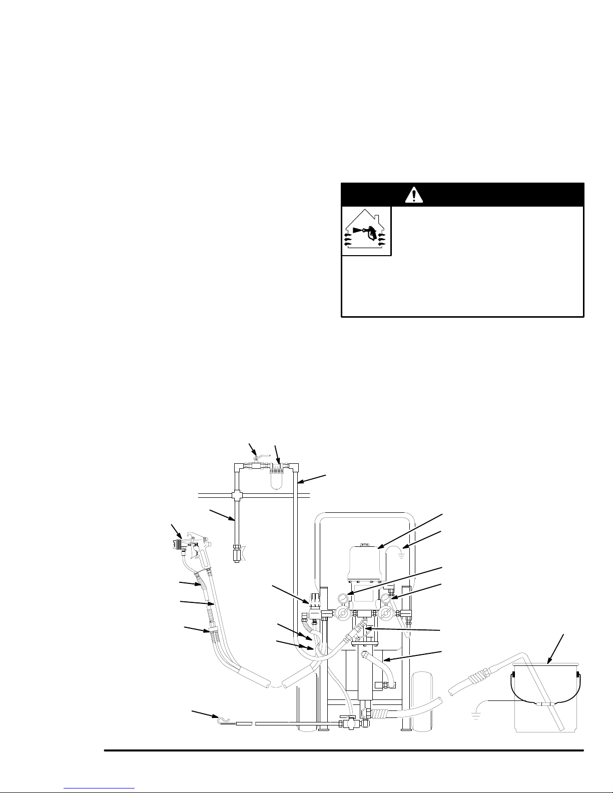
KEY
Components
A
B
C
D
E
you must supply:
Bleed-type master air valve
Required for pump, order
part no. 107–142, 1/4” npt(f)
Air filter
. Order part no.
106–149, 1/2 npt(f)
Air supply line
Grounded 5 gallon metal pail
Air line moisture trap
55
19
64b
64b
Components supplied with package:
1
30:1 President pump
2
Fluid heater
3
Back pressure regulator
28
Fluid filter (not visible)
29
Filter drain valve (not visible)
AB
E
3
28
29
C
31a
Pump air regulator
31b
Gun air regulator
32
Bleed–type air valve
55
Air-assisted airless spray gun
64a
Gun fluid hose
64b
Gun air hose
66
Pump ground wire
1
66
31b
31a
32
2
D
8
Fig.
1
Page 6

Setup
III. Unpack the system.
1. In
addition to the assembled unit, these compo
nents are packed separately: suction assembly
hose set, gun. In Fig. 1 items identified with a
number are supplied with the system. Items identi
fied with a letter are supplied by you.
2.
These are the manuals you should receive:
306–981
308–176
307–273
307–805
306–860
308–167
306–861
308–136 Cart
30:1 President pump
Air-Assisted Airless spray gun
Fluid filter
Fluid heater
Back pressure regulator
Air regulator
Ball valve
,
IV. Connect the hose set and gun to the
system.
1.
Connect the air hose (64b
regulator (31b) and the air inlet of the spray gun
(55). These are 1/4–18 swivel fittings.
2.
Connect one blue fluid hose (64a
(28) outlet. Connect the other blue fluid hose to the
back pressure regulator (3) outlet. These are
1/4–18 swivel fittings.
See
Fig. 1 and 2.
) between the gun air
) to the fluid filter
V. Ground the system.
To
reduce the risk of static sparking, ground the
pump and all other equipment used or located in
the spray area. Check your local electrical code for
detailed grounding instructions for your area and
type of equipment.
Also read .
page 4
1.
Pump
connected to the air motor grounding lug. Connect
the clamp end of the ground wire to a true earth
ground. Connect the clamp end of the ground wire
to a true earth ground.
2.
Air and fluid hoses
a maximum of 500 ft. (150 m) combined hose
length to ensure grounding continuity
FIRE OR EXPLOSION HAZARD
: one end of the ground wire (66) is already
WARNING
Ground all of this equipment.
on
: use only grounded hoses with
.
3.
Connect the whip hose (19) to the fluid inlet of
the spray gun (55). These are 1/4–18 swivel fit
tings.
4. V
erify that all fittings throughout the system are
tightened securely
Use a tie strap to secure the insulated hose to the
5.
leg of the cart. This provides strain relief so that
tugs on the heavy hoses don’t damage the hose
connections.
To
fluid filter (28) outlet
To
gun air regulator (31b) outlet
T
o back pressure regulator (3) outlet
64b
64a
54
.
55
19
Ref
-
64a
3.
Heater:
trical outlet. If you use an extension cord, be sure
it is a 3-wire grounded cord which is properly sized
for the heater
Air compressor
4.
recommendations.
Spray gun:
5.
tion to properly grounded air and fluid hoses and
pump.
Object being sprayed:
6.
7.
Fluid supply container:
by plugging into a properly grounded elec
.
: according to manufacturer’s
grounding is obtained through connec
according to local code.
according to local code.
-
-
Fig. 2
8.
All solvent pails used when flushing
local code. Use only metal pails, which are con
ductive. Do not place the pail on a non-conductive
surface, such as paper or cardboard, which inter
rupts the grounding continuity
, according to
.
-
-
Page 7

System Component Information
I. How to use the air–assisted airless
spray gun.
With
an air-assisted airless spray gun, the spray tip
shapes the fluid into a fan pattern. Air from the air cap
further atomizes the fluid and completes the atomiza
tion of the paint tails into the pattern to produce a more
uniform pattern.
The
spray gun has a built-in lead and lag operation. When
triggered,
When
flow
the gun emits air before the fluid is discharged.
the trigger is released, the fluid stops before the
stops. This helps assure
the spray is atomized and
prevents fluid buildup on the air cap.
NOTE: The gun air and fluid inlets have 1/4–18 npsm
(R1/4–19) compound male threads that are compatible
with
NPSM and BSP female swivel connectors.
1.
Use the fan pattern valve (E) can be used to
reduce the pattern by about 25% of the total pat
tern width. As the valve is opened, the pattern will
reduce slightly
. The tip used designates the total
width of the spray pattern.
2. T
o unlock the gun trigger safety, turn the safety so
it is parallel with the trigger
safety
, turn the safety to a right angle with the trig
ger
. See Fig. 3.
. T
o lock the gun trigger
-
air
-
-
II. How to change the spray pattern
direction.
1. Relieve
2.
Install a spray tip in the gun. Rotate the air cap
(the spray tip rotates with it) to determine the
direction of the spray pattern. See Fig. 4.
V
ertical Spray Pattern
Fig. 4
the air and fluid pressure.
Horizontal Spray Pattern
0791
1
UNLOCKED
2
LOCKED gun trigger safety
gun trigger safety
Fig. 3
E
2
1
0795A
Page 8

System Component Information
III. Fluid heater.
See
Fig. 5.
The heater (3) used in this system is a high mass
heater
. Always circulate the fluid when the heater is
operating to prevent overheating and damaging the
fluid. Do not use catalyzed material in this heater
.
IV. How to use the 3–way valve.
See
Fig. 5.
Heated systems require that the fluid circulate
constantly when the heater is turned on. The 3-way
valve (7) supplied with this system allows you to drain
or circulate the fluid. The words
are marked on the valve.
1.
In the
Drain
position and with the gun untriggered,
the fluid returns from the gun, to the back pressure
regulator (3), to the hose (19) and to the 3–way
valve (7) which directs the fluid out the drain hose
(8). This position is used when flushing the system
and when relieving system pressure.
2.
In the
Circulate
fluid returns from the gun, to the back pressure
regulator (3), to the hose (19) and to the 3–way
valve (7) which directs the fluid back into the pump
intake. This position is used during normal opera
tion and it helps keeps the fluid at a constant
temperature.
position, with the gun untriggered,
Drain
and
Circulate
V. How to adjust the air and
back pressure regulators. See
This system has two air regulators. As you look at the
system, the regulator (31a) on the left of the pump
regulates air to the gun and the regulator (31b) on the
right regulates air to the pump.
1.
Always open air regulators slowly to prevent surg
ing during startup.
2. T
o open the regulator
the T–handle IN (clockwise). T
OUT (counterclockwise) to close off the air flow
Be sure the jam nut under the T–handle does not
interfere with your adjustments. T
nut to lock in the setting, if desired.
3.
The back pressure regulator (3), located on the
fluid return side of the circulating system, acts as a
flow control. Use it to balance the pressure of the
circulating fluid so that the pump sucks in a suf
cient volume of fluid without running too fast or too
slow. T
fluid and slow down the pump. T
OUT (counterclockwise) to allow more flow which
speeds up the pump. See Fig. 6.
-
4. T
fluid to flow
urn the regulator IN (clockwise) to restrict
o open the back pressure regulator
, turn the knob IN (clockwise).
, which allows air to flow
urn the T–handle
ighten the jam
urn the regulator
Fig. 6.
-
, turn
.
fi-
, which allows
3
19
8
7
Fig. 5
5.
2
Adjust the back pressure regulator only when the
gun is triggered and fluid is flowing through the
regulator for an accurate setting.
3
31a
31b
CCW
CW
Fig. 6
Page 9

Operation
I. Pressure relief procedure
WARNING
To
reduce the risk of serious injury
splashing fluid or solvent in the eyes or on the skin,
always follow the procedure below when you stop
spraying or shut of
f the pump, check or service any
part of the system, or install, clean or change spray
tips.
1.
Engage the gun trigger safety
urn off the heater (turn to
2. T
urn the 3-way valve (7) to
3. T
4.
Close the bleed-type master air valve (A,14).
5.
Close the air regulators (31a,31b).
6.
Disengage the gun trigger safety
7.
Hold the gun firmly to a grounded metal pail.
T
rigger the gun to relieve pressure.
8.
Engage the gun trigger safety
Open the drain valve (29), having a container
9.
ready to catch the drainage.
If you suspect that the spray tip or hose is completely
clogged or that pressure has not been fully relieved,
very slow loosen the tip guard retaining nut or hose
end coupling and relieve pressure gradually
tip or hose obstruction.
, including
.
0).
Drain.
.
.
. Clean the
II. Flush the pump before the first use.
Flush
with a solvent compatible to your fluid. Consult
the fluid manufacturer’s literature for recommenda
tions. See
Flushing
on page 12.
-
III. Prime the system.
See
Fig. 7.
1.
Remove the air cap and spray tip from the gun.
2.
Close the filter drain valve (29).
3.
Put the suction tube into the fluid supply container
4.
Hook the drain hose (8) on the waste pail.
5. T
urn the 3-way valve (7) to the
6. T
urn the back pressure regulator (3) all the way
out (counterclockwise)
7.
Make sure the air regulators (31a,31b) are closed.
8.
Open the master air valves (A,32).
Drain
position.
.
A
C
KEY
A Bleed-type
C
Air supply line
2
Fluid heater
3
Back pressure regulator
7
3–way valve
28
Fluid filter (not visible)
29
Filter drain valve
(not visible)
31a
Pump air regulator
31b
Gun air regulator
32
Bleed–type air valve
master air valve)
31b
3
28
29
31a
32
2
7
8
Fig. 7
Page 10

Operation
NOTE:
until air is purged.
9.
10.
11. T
12.
In the next steps, the pump will cycle quickly
Slowly turn on the pump air regulator (31b) until
the pump cycles slowly
drain hose, turn the 3-way valve to
Hold the gun firmly to the grounded metal waste
pail. T
rigger the gun while adjusting pressure at
the pump air regulator (31b) just enough to purge
the air and storage solvent out of the system.
When new fluid comes from the gun, release the
trigger
. Engage the gun trigger safety
urn IN the back pressure regulator (3) to raise the
system pressure until the pump stops.
Raise the air pressure to the pump to 35 psi (2.4
bar). Adjust the back pressure valve to set the
pump cycle rate at 1 stroke every 10 seconds.
. When fluid flows from the
Circulate.
.
13. T
urn the heater dial to 3. When adjusting the
heater
, always allow the fluid to circulate and stabi
lize (about 10 minutes) before checking the tem
perature.
CAUTION
Be sure the fluid is circulating whenever the heater
is on to reduce the risk of damage to the fluid or
the heater
14.
Use the fluid manufacturer’s recommendations for
temperature and adjust the heater accordingly
unknown, set the temperature to 1
the outlet thermometer
temperature has stabilized. Do not allow the fluid
to exceed 140
manufacturer recommends higher temperatures.
15.
Spray fluid into a waste pail for about 10 seconds
to bring heated material to the gun.
16.
Hook the drain hose (8) on the fluid supply pail.
.
10_F (43_
. Do not proceed until the
_F (60_
C) unless your fluid
-
-
. If
C) at
10
308-462
Page 11

Operation
IV. How to set the fluid and air pressure.
1. Install
2.
3. T
4.
the spray tip and air cap on the gun.
Adjust the pump air pressure regulator until the
pressure shown on the fluid filter gauge is about
900 psi (63 bar). This should require approximately
30 psi (2.1 bar) air pressure to the pump.
est spray a pass or stationary horizontal pattern.
Hold the gun 10 to 12 in. (250 to 300 mm) from a
piece of paper
pass or spots at the ends of the stationary pattern
are likely at this point.
NOTE:
fluid pressure until they appear
the air to the gun.
Partially trigger the gun so only air is emitted. Set
the gun air regulator to 50 psi (3.5 bar).
. Stripes in the outer edges of the
If there are no stripes or spots, lower the
before
turning on
WARNING
This system has a maximum air working pressure
of 100 psi (7 bar) which produces a maximum fluid
working pressure of 3000 psi (210 bar). Higher
pressure can cause the system to rupture or mal
function and result in serious injury
With the fluid pressure set, check the pump cycle
7.
rate with the gun triggered and with the gun untrig
gered. With the gun untriggered, the pump should
cycle at 10 cycles per minute. Adjust the back
pressure regulator (3) to obtain the desired circula
tion rate. With the gun triggered, the cycle rate will
depend on tip size, but some circulation is always
desired.
8.
Use the gun air control valve (E) to adjust the
degree of atomization. Always use the lowest air
pressure possible for the most ef
.
ficiency.
E
-
-
-
5.
Retest the spray pattern. If there are no stripes or
spots, you are ready to start spraying.
6.
If there are stripes or spots in the spray pattern,
raise the pump air pressure until you raise the fluid
outlet pressure by about 100 psi (7 bar) and try
again. Continue to raise the fluid pressure in
100
psi (7 bar) increments until the pattern is full
and clean. Do not exceed 100 psi (7 bar) incoming
air pressure or 3000 psi (210 bar) fluid working
pressure.
NOTE: Always use the lowest fluid and air pres
sure required for good atomization and spray pat
tern for maximum fluid ef
approximately 50 psi (3.3 bar) will cause turbu
lence in the fan pattern, dirty air caps and slower
production capability
.
ficiency
. Air pressure over
Fig. 8
0795A
V. You are now ready for production
spraying.
NOTE:
T
-
-
-
VI. When to shut down the system.
Shut
before checking, adjusting, cleaning or repairing the
system. Always follow the
on page 9.
If you stop spraying for more than 30 minutes,
urn of
f the heater to prevent overheating the fluid.
down the system at the end of the work shift and
Pressure relief procedure
,
308-462
11
Page 12

Operation
I. When to flush.
D Before
D
D
D
the first time use
When changing colors
Before fluid can dry or settle out in a dormant sys
tem (observe the recommended fluid pot life on cat
alyzed fluids)
Before storing the system
urn of
1. T
2.
Remove the air cap and spray tip from the gun and
-
clean separately. Do not reinstall at this time.
f the heater and allow the system to cool.
-
3.
Open the filter drain valve (29). Unscrew the fluid
filter (28) bowl. Remove the screen. See manual
307–273. Reinstall the bowl without the screen.
II. How to flush.
WARNING
Before
you flush, be sure the heater is turned of
and the fluid has cooled. This is to reduce the risk
of a fire or explosion and serious injury
A
.
3
28
29
4.
Hook the drain hose (8) on the waste pail.
5. T
urn the 3-way valve (7) to
Drain.
f
urn the back pressure regulator (3) all the out
6. T
(counterclockwise).
KEY
A Bleed-type
C
Air supply line
2
Fluid heater
3
Back pressure regulator
7
C
3–way valve
28
Fluid filter (not visible)
29
Filter drain valve
(not visible)
31a
Pump air regulator
31b
Gun air regulator
32
Bleed–type air valve
master air valve)
31b
31a
32
2
8
Fig. 9
12
308-462
7
Page 13

Operation
7. Put
8.
NOTE:
closed during flushing.
9.
10.
11.
12. T
the suction tube into a grounded metal pail
with about 1 gal. (4 liters) of a compatible solvent.
Make sure the air regulators (31a,31b) are closed.
The gun air regulator (31a) always stays
Open the master air valves (A,14).
Slowly turn on the pump air regulator (31b) until
the pump cycles slowly
drain hose, turn the 3-way valve to
the air pressure to 40 psi (2.8 bar).
Hold the gun firmly against and aimed into the
grounded metal waste pail. T
adjust the pump air regulator setting until the fluid
flows freely
the fluid arrives.)
rigger the gun and decrease the pump air regu
lator pressure as much as possible without stalling
the pump, and pump out all the solvent (air comes
through the gun).
. (Some air will spit from the gun until
. When fluid flows from the
Circulate.
rigger the gun. Slowly
Set
13.
For a first–time flush
the solvent for 30 seconds.
For flushing after spraying fluid
and circulate the solvent until the system is thor
oughly cleaned. Repeat with clean solvent,
if necessary
14.
Release the trigger and engage the gun trigger
safety.
15.
Remove the suction hose from the solvent and
place it in an empty container
16. T
urn the 3–way valve to
from the system.
17. T
urn the pump air regulator all the way out. Close
the master air valves (A,14).
18.
Clean the filter screen, air cap and spray tip sepa
rately.
19.
Open the filter drain valve (29). Remove the filter
-
bowl and reinstall the filter screen.
20.
Thoroughly clean the inside and outside of the
suction tube.
.
: trigger the gun and circulate
: trigger the gun
-
.
Drain
to purge solvent
-
308-462
13
Page 14

Parts
Model 237–423, Series A
Includes
Ref
No. Part No. Description Qty
1 223–586 PRESIDENT PUMP
2 220–522 VISCON
3 206–819 BACK PRESSURE VALVE
4 100–840
5 162–453
6 166–998
7 214–711 3–WA
8 206–965 DRAIN HOSE, 1/4” ID,
9 206–962 CHECK VAL
10 159–801 90_ ADAPTER UNION,
11 158–683 ELBOW 1
12 235–022
13 156–849
14 107–219
15 112–408
16 110–160 CORD ASSY
17 224–044 CART
19 206–966 HOSE
20 214–960 SUCTION HOSE, 3/4 npt(mbe),
21 165–767 SUCTION TUBE, 3/4 npt(f) 1
22 100–016 LOCKW
23 100–270 CAPSCREW
26 179–749
27 150–286
28 218–029
29 210–658
30 156–877
31 104–267 AIR REGULATOR
32 107–142 BLEED TYPE AIR VAL
44 206–994 THROAT SEAL LIQUID, 8 oz.
46 155–470
48 101–180 AIR PRESSURE GAUGE,
items 1 to 72
See 308–106 for parts
See manual 307–805 for parts
See manual 307–860 for parts
90
NIPPLE, 1/4 npt x 1/4 npsm
FLUID INLET MANIFOLD, 1/4 npt(f) x
3/4 npt(f) x 3/4 npsm(f) swivel
See 306–861 for parts
cpld 1/4 npsm(f)
3/8 npt(f) x 1/2 npsm(f) swivel
HOSE, pump to heater
NIPPLE, 3/8 npt x 3/8–18.6 sf
BUSHING, 3/4 npt(m) x 1/2 npt(f)
90
1/2 npt(m), includes nut,
washer
600V
6.5’ (2 m) long
See 308–136 for parts
1/4” ID x 18” (6 mm x 457 mm)
3/4” ID x 3.5’ (19 mm ID x 1.06 m)
1/4–20 x 5/8” (16 mm) long
AIR MANIFOLD, 1/2 npt inlet,
two 1/2 npt outlets
ADAPTER, 3/8 npt (m x f)
FLUID FIL
See 307–273 for parts
BALL VALVE, 3/8 npt x 1/4 npt (mbe),
See 306–861 for parts
NIPPLE, 1/2 npt, 2.5” (63.5 mm)
0–125 psi (0–9 bar) range
See 308–167 for parts
1/2 npt (m x f)
not shown
90
1/2 npt(m) x 1/2 npsm(f) swivel
0–200 psi (0–14 bar)
2
FLUID HEA
_ ELBOW
_ CORD GRIP ELBOW
, 20 AMP
_ ADAPTER UNION,
, street, 1/4 npt(mxf)
Y BALL VALVE, 1/4 npt(m),
VE, 3/8 npt (mbe)
, and grommet
, heater
, 105_C (221
, portable
ASHER, spring, 1/4”
, hex hd,
TER
TER, 120V
, 12 A
VE,
,
WG,
_F),
Ref
No. Part No. Description Qty
49 218–093
1
50 222–297 45_ ADAPTER UNION,
1
51 158–491
1
52 166–999 ELBOW
4
4
53 102–254 SCREW
1
55 223–283 AIR
1
56 182–411 SPRAY
1
59 167–002 INSULATOR,
1
60 100–527 W
61 155–494 90_ ADAPTER UNION
1
62 100–509
1
63 188–595 PUMP MOUNTING PLATE 1
1
64 237–494 FLUID & AIR HOSE SET
1
64a
1
64b 237–423
1
65 102–814 FLUID GAUGE 1
66 237–569 GROUND WIRE 1
1
67 169–797
68 169–795
1
69 100–139
71 214–699
1
2
72 157–416 SWIVEL ADAPTER 1
2
Manual
1
1
1
1
3
2
1
1
1
2
Assembly
Changed
Package
AIR HOSE, cpld 1/2 npt(mbe),
1/2” ID X 22” (13 mm ID X 559 mm)
1/2 npt(m) x 1/2 npsm(f) swivel
NIPPLE, 1/2 npt, 1 5/8” (41 mm) long
, reducing street,
1/2 npt(m) x 1/4 npt(f)
, hex hd, 1/4–20 x
7/8” (22 mm) long
ASSISTED AIRLESS
SPRA
Y GUN
See
manual 308–136 for parts
TIP
heat
ASHER, wrought, 1/4”
3/8 npt(m) x 3/8 npt(f) swivel
PLUG, pipe, sq hd, 1/4 npt
two fluid hoses, cpld 1/4 npsm(fbe)
swivel, spring guards both ends,
1/4” ID x 25’ (6 mm ID x 7.6 m)
one air hose, cpld 1/4–18 npsm,
5/16” ID x 25’ (7.9 mm ID x 7.6 m)
and hose insulator
NIPPLE, 1/4 npsm x 1/8 npt
MANIFOLD, 1/8 npt(f)
PLUG, hex socket, 1/8 npt 1
WHIP HOSE, cpld 1/4 npsm (fbe),
3/16” ID x 6 feet
(4.8 mm x 1.8 m)
Change
Summary
Part
Status
Old
New
Old
New
Old
New
Delete(1)
Add (1)
Delete
Old
New
Ref
Part No. Name
No.
15
102–363
15
112–408
19
214–701
19
206–966
64
222–407
64
237–494
––
64b
169–797
67
159–840
70
214–701
71
214–699
71
1
1
1
1
4
1
1
4
2
1
3
, includes:
1
3
1
1
Elbow
Elbow
Hose
Hose
Hose set
Hose set
Hose
Nipple
Adapter
Hose
Hose
14
308-462
Page 15

Model 237–423, Series A
Includes
items 1 to 72
52
48
3
4
5
4
5
59
60
Parts
53
53
1
66
15
14
16
5
31
62
30
19
26
C
32
30
48
31
46
30
50
51
2
13
61
28
27
29
62
5
65
62
12
9
B
10
C
A
72
49
A
63
17
22
23
4
55,56
B
67
11
Ref
12
71
64b
67
8
68
69
67
64a
20
21
6
4
7
308-462
15
Page 16

Technical
Data
Maximum
Maximum
Pump
Gun
Heater
Wetted
The
Fluid W
Air Operating Pressure
Air Consumption
Air Consumption
Electrical Requirement
Parts
Pump
Fluid heater
Gun
Fluid filter
Fluid fittings
Back
Fluid hose and tubing
NOTE: all 304, 316 and 17–4 pH SST are electropolished and/or passivated.
Delrin
orking Pressure
.
. .
. . . . . . . . . . . . . . . . . . . . . . .
. . . . . . . . . . . . . .
.
. . . . . . . . . . . . . . . . . . . . . . . . . . . . . . . . . . .
.
. . . . . . . . . . . . . . . . . .
.
. . . . . . . . . . . . . . . . . . . . . . . . . . . . . . . . . . .
.
. . . . . . . . . . . . . . . . . . . . . . . . . . . . . . . . . . . . . . . .
pressure fluid regulator
303/416 stainless steel, Delrin, chrome plated stainless steel
is a registered trademark of the Du Pont Company
.
. . . . . . . . . . . . . . . . . . . . . . . .
.
. . . . . . . . . . . . . . . . . . . . . . . . .
free flow:
.
. . . . . . . . . . . . . . . . .
. . . . . . . . . . . . . . . . . . . . . . . . . . . . . . . . . . . . .
20 scfm at 100 psi (0.56 m3/min at 6.9 bar)
8 scfm at 60 psi (0.22 m3/min).
2000 W
Carbon steel, chrome and zinc plating, PTFE,
304/316/420/17–4
tungsten carbide, leather
303
stainless steel, carbide, UHMWPE CV75,
polyethylene, PTFE, Delrin
304/316
.
. . . . . . . . . . . . . . . . . . .
cadmium
stainless steel, polyethylene
and zinc–plated carbon steel,
.
3000 psi (210 bar)
100 psi (6.9 bar)
atts, 1
10 V
pH stainless steel,
304 stainless steel
Carbon steel,
Carbon steel
T
ungsten carbide,
, 16.7 Amp
.
PTFE,
Nylon.
Graco Warranty and Disclaimers
WARRANTY
warrants all equipment manufactured by it and bearing its name to be free from defects in fluid and workmanship on the date of
Graco
sale
by an authorized Graco distributor to the original purchaser for use. As purchaser’s sole remedy for breach of
will,
for a period of twelve months from the date of sale, repair or replace any part of the equipment proven defective. This warranty
applies
only when the equipment is installed, operated and maintained in accordance with Graco’
This
warranty does not cover
plication,
component
structures,
maintenance of structures, accessories, equipment or fluids not supplied by Graco.
This
verification
will
workmanship,
DISCLAIMERS AND LIMITATIONS
The terms of this warranty constitute purchaser’s sole and exclusive remedy and are in lieu of any other warranties (express or
implied),
ties, including product liabilities, based on negligence or strict liability. Every form of liability for direct, special or consequential
damages
action
EQUIPMENT NOT COVERED BY GRACO WARRANTY
Graco makes no warranty, and disclaims all implied warranties of merchantability and fitness for a particular purpose, with
respect
tured
purchaser
abrasion, corrosion,
parts. Nor shall Graco be liable for malfunction, damage or
accessories, equipment or fluids not supplied by Graco, or the improper design, manufacture, installation, operation or
warranty is conditioned upon the prepaid return of the equipment claimed to be defective to an authorized Graco distributor for
of the claim. If the claimed defect is verified, Graco will repair or replace free of charge any defective parts. The equipment
be returned to the original purchaser transportation prepaid.
repairs will be made at a reasonable charge, which charges may include the costs of parts, labor and transportation.
including warranty of merchantability or warranty of fitness for a particular purpose
or loss is expressly excluded and denied. In no case shall Graco’s liability exceed the amount of the purchase price. Any
for breach of warranty must be brought within two (2) years of the date of sale.
to accessories, equipment, fluids, or components sold
by Graco (such as electric motor
with reasonable assistance in making any claim for breach of these warranties.
, and Graco shall not be liable for
inadequate or improper maintenance, negligence, accident, tampering, or substitution of non–Graco
, switches, hose, etc.) are subject to the
, any malfunction, damage or wear caused by faulty installation, misap
wear caused by the incompatibility with Graco equipment of
If inspection of the equipment does not disclose any defect in fluid or
but not manufactured by Graco. These items sold, but not manufac
warranty
, if any
s written recommendations.
, and of any non–contractual liabili
, of their manufacturer
this warranty
. Graco will provide
, Graco
-
-
-
Graco
TO
PLACE AN ORDER
utor
, or call this number to identify the distributor
closest to you:
16
308-462
1–800–367–4023 T
Foreign Offices:
, contact your Graco distrib
oll Free
Sales
Offices:
Atlanta, Chicago, Dallas, Detroit, Los Angeles, Mt. Arlington (N.J.)
Canada, England, Korea, Switzerland, France, Germany
GRACO INC. P.O. BOX 1441
PRINTED
IN U.S.A.
Phone Numbers
-
308–462 September,
FOR TECHNICAL ASSIST
information or assistance regarding the application of
Graco equipment:
MINNEAPOLIS, MN
1994, Revised November
1–800–543–0339 T
, Hong Kong, Japan
55440–1441
, 1994
ANCE,
service repair
oll Free
 Loading...