

Page 1

Instructions - Parts List
™
308391J
Power-Star
Used to pump high volumes of petroleum and synthetic based oils. For professional use
only.
Model No. 236754, Series A
1:1 Ration Universal Pump and Reciprocator
Model No. 236752, Series A
Reciprocator Only
1500 psi (10 MPa, 103 bar) Maximum Hydraulic Input Pressure
1500 psi (10 MPa, 103 bar) Maximum Fluid Outlet Pressure
Important Safety Instructions
Read all warnings and instructions in this
manual. Save these instructions.
EN
This pump is designed to be used only in pumping
non-corrosive and non-abrasive oils and lubricants.
Any other use of the system can cause unsafe
operating conditions and result in components
rupture, fire, or explosion which can cause serious
injury, including fluid injection.
Page 2

Contents
Warnings . . . . . . . . . . . . . . . . . . . . . . . . . . . . . . . . . 3
Installation . . . . . . . . . . . . . . . . . . . . . . . . . . . . . . . . 5
Pump Accessories . . . . . . . . . . . . . . . . . . . . . . . 5
Grounding . . . . . . . . . . . . . . . . . . . . . . . . . . . . . . 5
Hydraulic Power Supply . . . . . . . . . . . . . . . . . . . 6
Hydraulic Components . . . . . . . . . . . . . . . . . . . . 7
Operation . . . . . . . . . . . . . . . . . . . . . . . . . . . . . . . . . 8
Pressure Relief Procedure . . . . . . . . . . . . . . . . . 8
Before Starting the Pump . . . . . . . . . . . . . . . . . . 8
To Start the Pump . . . . . . . . . . . . . . . . . . . . . . . . 8
Shutdown and Care . . . . . . . . . . . . . . . . . . . . . . 9
Emergency Stop Procedure . . . . . . . . . . . . . . . . 9
Troubleshooting . . . . . . . . . . . . . . . . . . . . . . . . . . . 10
Repair . . . . . . . . . . . . . . . . . . . . . . . . . . . . . . . . . . . 11
Disassembly . . . . . . . . . . . . . . . . . . . . . . . . . . . 11
Reassembly . . . . . . . . . . . . . . . . . . . . . . . . . . . 12
Intake Valve . . . . . . . . . . . . . . . . . . . . . . . . . . . . 13
Displacement Pump . . . . . . . . . . . . . . . . . . . . . 14
Notes . . . . . . . . . . . . . . . . . . . . . . . . . . . . . . . . . . . . 15
Parts . . . . . . . . . . . . . . . . . . . . . . . . . . . . . . . . . . . . 16
Technical Data . . . . . . . . . . . . . . . . . . . . . . . . . . . . 19
Graco Standard Warranty . . . . . . . . . . . . . . . . . . . . 20
2 308391J
Page 3
Warnings
Warnings
The following warnings are for the setup, use, grounding, maintenance, and repair of this equipment. The exclamation point symbol alerts you to a general warning and the hazard symbols refer to procedure-specific risks. When
these symbols appear in the body of this manual or on warning labels, refer back to these Warnings. Product-specific
hazard symbols and warnings not covered in this section may appear throughout the body of this manual where
applicable.
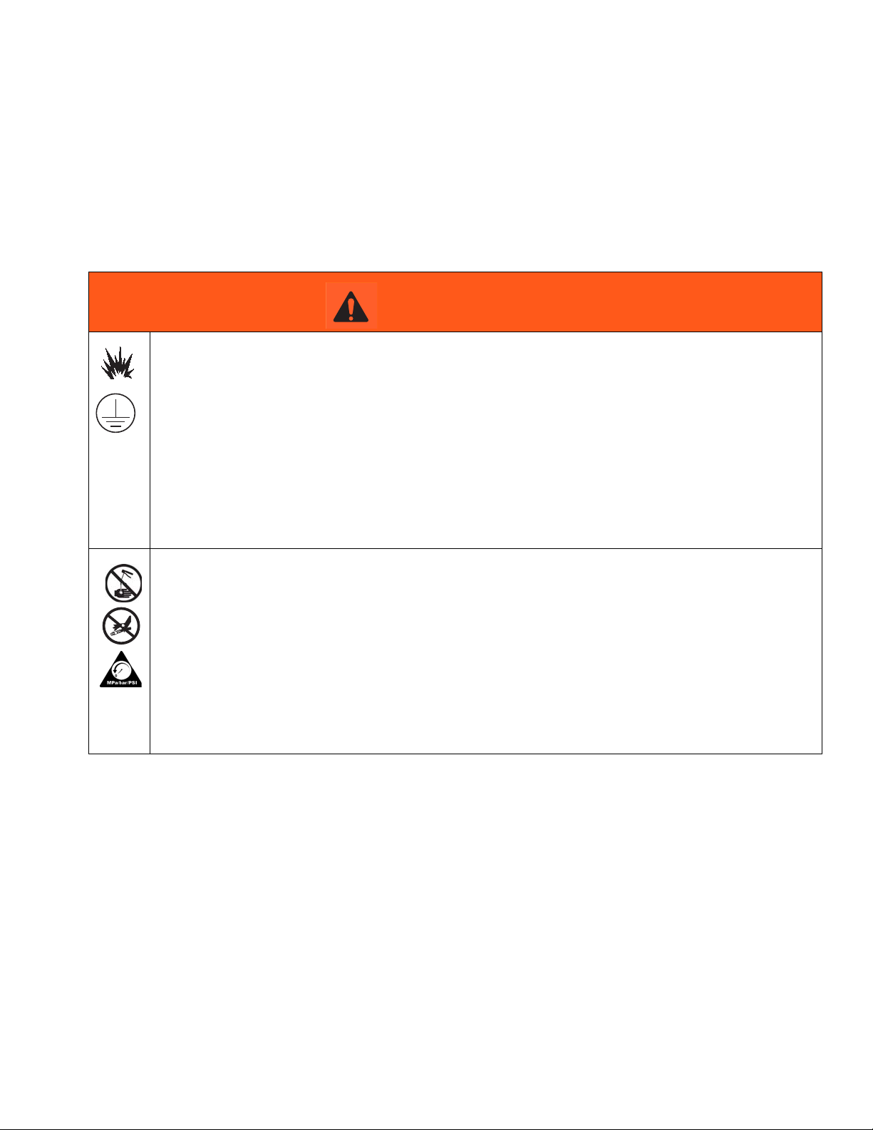
WARNING
FIRE AND EXPLOSION HAZARD
When flammable fluids are present in the work area, such as gasoline and windshield wiper fluid, be
aware that flammable fumes can ignite or explode. To help prevent fire and explosion:
• Use equipment only in well ventilated area.
• Eliminate all ignition sources, such as cigarettes and portable electric lamps.
• Keep work area free of debris, including rags and spilled or open containers of solvent and gasoline.
• Do not plug or unplug power cords or turn lights on or off when flammable fumes are present.
• Ground all equipment in the work area.
• Use only grounded hoses.
• Stop operation immediately if static sparking occurs or you feel a shock. Do not use equipment
until you identify and correct the problem.
• Keep a working fire extinguisher in the work area.
SKIN INJECTION HAZARD
High-pressure fluid from dispensing device, hose leaks, or ruptured components will pierce skin. This
may look like just a cut, but it is a serious injury that can result in amputation. Get immediate surgical
treatment.
• Do not point dispensing device at anyone or at any part of the body.
• Do not put your hand over the fluid outlet.
• Do not stop or deflect leaks with your hand, body, glove, or rag.
• Follow the Pressure Relief Procedure when you stop dispensing and before cleaning, checking, or
servicing equipment.
• Tighten all fluid connections before operating the equipment.
• Check hoses and couplings daily. Replace worn or damaged parts immediately.
308391J 3
Page 4
Warnings
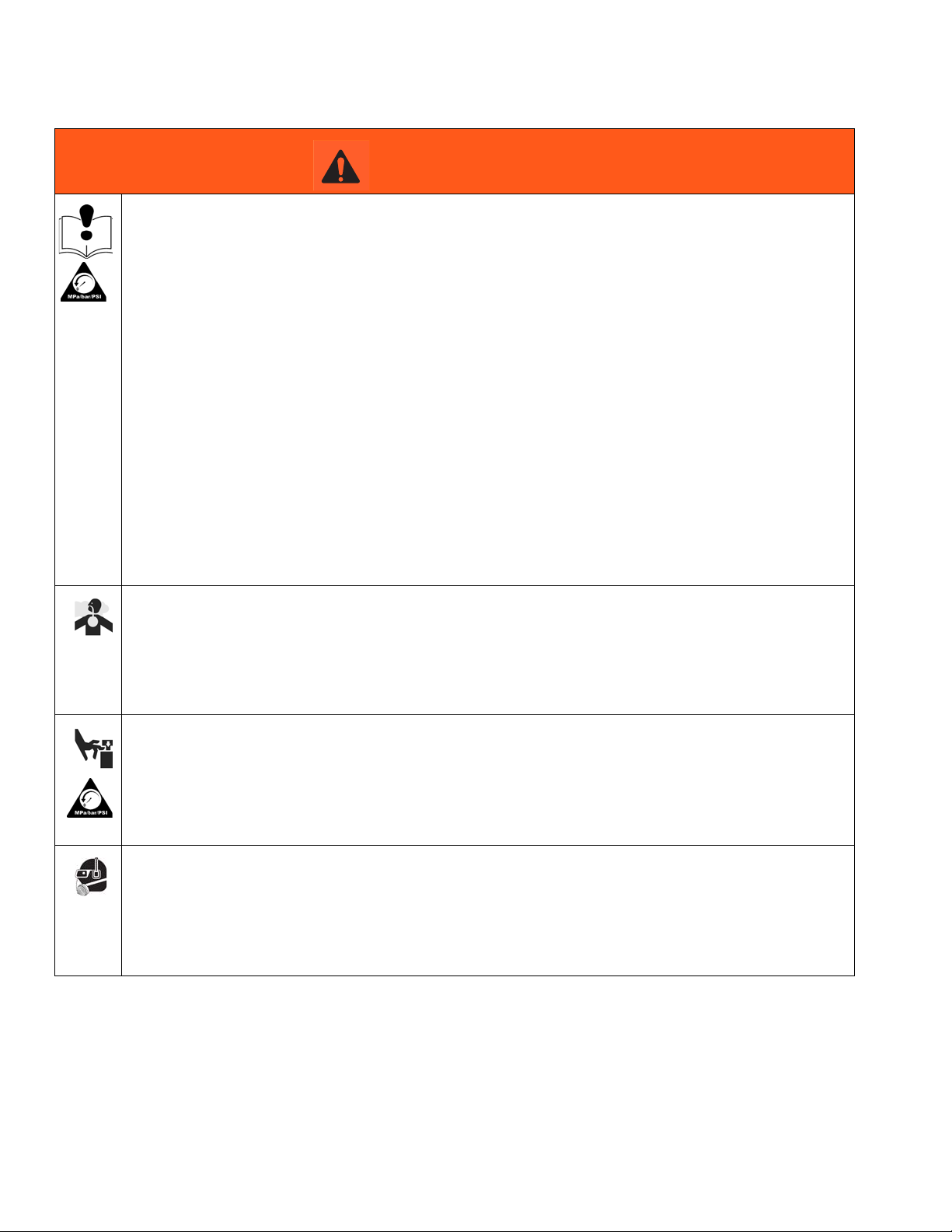
WARNING
EQUIPMENT MISUSE HAZARD
Misuse can cause death or serious injury.
• Do not operate the unit when fatigued or under the influence of drugs or alcohol.
• Do not exceed the maximum working pressure or temperature rating of the lowest rated system com-
ponent. See Technical Data in all equipment manuals.
• Use fluids and solvents that are compatible with equipment wetted parts. See Technical Data in all
equipment manuals. Read fluid and solvent manufacturer’s warnings. For complete information
about your material, request MSDS from distributor or retailer.
• Do not leave the work area while equipment is energized or under pressure.
• Turn off all equipment and follow the Pressure Relief Procedure when equipment is not in use.
• Check equipment daily. Repair or replace worn or damaged parts immediately with genuine manufacturer’s replacement parts only.
• Do not alter or modify equipment. Alterations or modifications may void agency approvals and create
safety hazards.
• Make sure all equipment is rated and approved for the environment in which you are using it.
• Use equipment only for its intended purpose. Call your distributor for information.
• Route hoses and cables away from traffic areas, sharp edges, moving parts, and hot surfaces.
• Do not kink or over bend hoses or use hoses to pull equipment.
• Keep children and animals away from work area.
• Comply with all applicable safety regulations.
TOXIC FLUID OR FUMES HAZARD
Toxic fluids or fumes can cause serious injury or death if splashed in the eyes or on skin, inhaled, or
swallowed.
• Read MSDSs to know the specific hazards of the fluids you are using.
• Store hazardous fluid in approved containers, and dispose of it according to applicable guidelines.
• Always wear chemically impermeable gloves when spraying, dispensing, or cleaning equipment.
MOVING PARTS HAZARD
Moving parts can pinch, cut or amputate fingers and other body parts.
• Keep clear of moving parts.
• Do not operate equipment with protective guards or covers removed.
• Pressurized equipment can start without warning. Before checking, moving, or servicing equipment,
follow the Pressure Relief Procedure and disconnect all power sources.
PERSONAL PROTECTIVE EQUIPMENT
Wear appropriate protective equipment when in the work area to help prevent serious injury, including
eye injury, hearing loss, inhalation of toxic fumes, and burns. This protective equipment includes but is
not limited to:
• Protective eyewear, and hearing protection.
• Respirators, protective clothing, and gloves as recommended by the fluid and solvent manufacturer
4 308391J
Page 5
Installation
Y
Z
Installation
Maximum Working Pressure of Accessories
To reduce the risk of serious injury including fluid
injection and splashing in the eyes or on the skin,
which may be caused by component ruptures, all
accessories added to the reciprocator power supply
side of the pump fluid outlet side must have at least a
1500 psi (10 MPa, 103 bar) maximum working
pressure.
Pump Accessories
Suction Tube Kit: A suction tube kit is available for
siphoning from 55 gallon containers.
Intake Tube: To install, apply PTFE tape to the female
threads at the top of the tube (Q). Screw the tube tightly
into the intake housing of the stubby pump.
Low-Level Cutoff Valve: To install, screw the low-level
cutoff valve into the bottom of the pump intake tube or
the suction tube. This valve closes the pump intake
when the fluid level is low, causing the pump to stall to
avoid running all day.
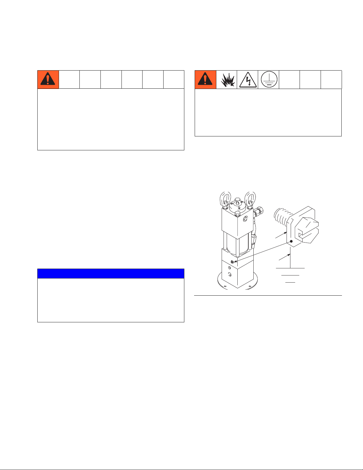
The equipment must be grounded to reduce the risk
of static sparking and electric shock. Electric or static
sparking can cause fumes to ignite or explode.
Improper grounding can cause electric shock.
Grounding provides an escape wire for the electric
current.
Pump: Use a ground wire and clamp. Remove the
ground screw (Z) and insert through the eye of the ring
terminal at end of ground wire (Y). Fasten the ground
screw back onto the pump and tighten securely. Connect the other end of the ground wire to a true earth
ground. (F
IG. 1)
NOTICE
A pump outlet drain valve is required in the system.
This valve helps relieve pressure in the
displacement pump and hose when shutting down
the system and in case of a clogged outlet hose.
Install the valve hose close the pump outlet.
Pump Outlet Drain Valve: Install a drain valve (D) close
to the pump fluid outlet assist in relieving fluid pressure
in the pump, hose, and dispense valve when the pump
is shut off.
Thermal Relief Kit: Install a Thermal Relief Kit (T) at the
pump fluid outlet.
Grounding
FIG. 1
Hydraulic and fluid hoses: Use only electrically con-
ductive hoses.
Hydraulic power supply: Follow manufacturer’s recom-
mendations.
Any pails used when flushing: Use only metal,
grounded pails when flushing. Make firm metal-to-metal
contact between the metal part of the dispense valve
and the pail. Use the lowest possible pressure.
308391J 5
Page 6
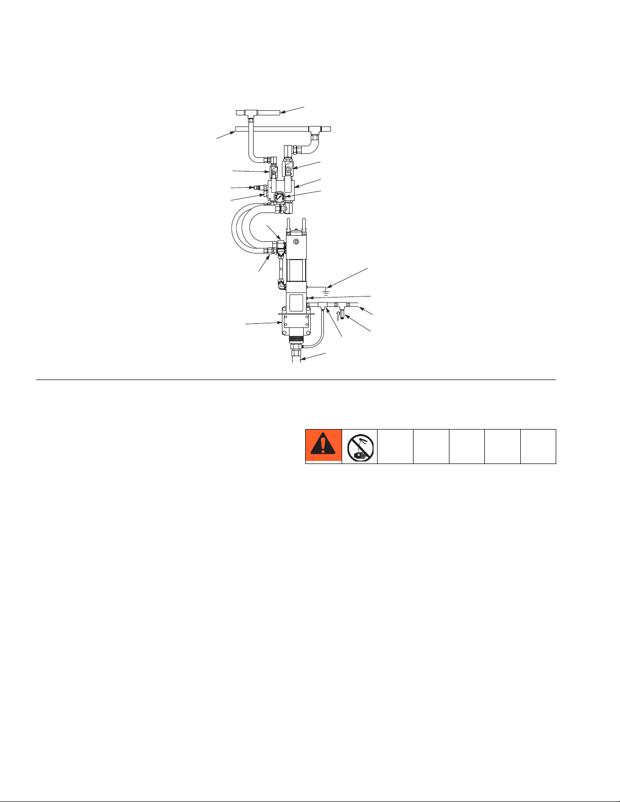
Installation
H
R
E
N
A
G
J
L
M
B
P
D
C
K
F
S
T
FIG. 2: Typical Installation
Key:
A Hydraulic Control (See manual 308395)
B Porous Plug (weep tube optional)
C Fluid Dispense Outlet
D Drain Valve (required)
E Hydraulic Return Line
F Hydraulic Outlet, 1 1/4 npt
G Return Line Shutoff Valve
H Hydraulic Inlet, 3/4 npt
J Hydraulic Supply Line Shutoff Valve
K Pressure Gauge
L Pressure Reducing Valve
M Flow Control Valve
N Hydraulic Supply Line (Use only Graco Hydraulic power
supply)
P Dispensed Material Supply Suction Hose Kit
R Ground Wire (required)
S Wall Mounting Bracket (See manual 308394)
T Thermal Relief Kit (required)
NOTE: The installation shown in FIG. 2 is only a guide.
For assistance in designing a system to suit your needs.
Contact your Graco representative.
Mount the pump to suit the type of installation planned.
Hydraulic Power Supply
To reduce the risk of damaging the hydraulic power supply, blow out all hydraulic lines with air, flush thoroughly
with solvent, and then blow out with air again before
connecting the lines to the motor.
Always plug the hydraulic inlets, outlets, and lines when
disconnecting them to avoid introducing dirt and other
contaminants to the system.
Carefully follow the manufacturers recommendations on
reservoir and filter cleaning, and periodic changes of the
hydraulic fluid.
6 308391J
Page 7

Installation
24
Hydraulic Components
Always turn off the hydraulic supply side valve (K)
first to avoid possible serious injury or component
damage. See the Typical Installation on page 6.
Drain Line: Remove the plug (24) from the pump
adapter, and install a 1/8 inch diameter weep tube, ending in a waste container. Monitor the weepage of
hydraulic fluid. If it seems excessive or increases suddenly, the reciprocator or pump throat seals may need to
be changed. (F
IG. 3)
Pump Isolation: The hydraulic fluid control has ball
valves on the supply and return sides of the manifold.
The ball valves isolate the hydraulic fluid control and
pump for servicing without stopping the hydraulic power
supply.
FIG. 3
Hydraulic Fluid Control: The hydraulic fluid control provides pressure regulator, and pump isolation. (F
Pressure Regulation: The hydraulic fluid control reduces
the hydraulic oil pressure to the operating pressure
required for the application.
Flow Regulation: The hydraulic fluid control limits the
maximum amount of oil flow to the motor to keep the
hydraulic motor within the cycle rate limit. This prevents
pump runaway. The limit on the Power-Star is 66 cpm.
308391J 7
IG. 2)
Page 8

Operation
Operation
Pressure Relief Procedure
Follow the Pressure Relief Procedure whenever
you see this symbol.
This equipment stays pressurized until pressure is
manually relieved. To help prevent serious injury from
pressurized fluid, such as skin injection, splashing
fluid and moving parts, follow the Pressure Relief
Procedure when you stop spraying and before
cleaning, checking, or servicing the equipment.
1. Close the supply line shutoff valve, and then the
return line shutoff valve.
2. Open the dispensing valve to relieve the pressure.
3. Place a container under the drain valve to catch any
drainage. Open the pump outlet drain valve.
4. Leave the drain valve open until you are ready to
dispense again.
NOTE: If you suspect that the dispensing valve, extension, or grease fitting coupler is clogged, or that the
pressure has not been fully relieved after following the
steps above, VERY SLOWLY loosen the coupler or
hose end coupling and relieve pressure gradually, then
loosen completely and clear the clog.
Before Starting the Pump
Recommended Hydraulic Oil
Use a Graco-approved Hydraulic Oil or a premium, ISO
grade 46 petroleum-based hydraulic oil containing rust
and oxidation inhibitors and anti-wear agents.
Before using any other type of oil in this motor contact
your Graco distributor. Unauthorized use of lesser grad
oil or substitutes may void the warranty.
1. Check the hydraulic fluid level in the hydraulic power
supply before each use, and add fluid as necessary
to fill the lines.
2. Flush the pump before using it for the first time to
remove the light oil that was left in after factory testing to protect the pump from corrosion. Be sure the
solvent used is compatible with the fluid to be
pumped and the pump’s wetted parts. See Technical Data, page 18. Flush until clean solvent comes
from the outlet hose.
To Start the Pump
1. Turn on the hydraulic power supply.
2. Open the return line shutoff valve (H) first, and
slowly open the hydraulic supply line shutoff valve
(K). (F
IG. 2)
3. Adjust the hydraulic inlet pressure from 500 to 1500
psi (3.5 to 10.3 MPa, 35 to 103 bar) with the regulator control adjustment (M) on the hydraulic fluid control (A). Increasing the inlet pressure increases the
outlet pressure. Decreasing the inlet pressure
decreases the outlet pressure.
4. Always use the lowest pressure possible to obtain
the desired results. This reduces pump wear.
8 308391J
Page 9

5. Never allow a pump to run dry of the fluid being
pumped. A dry pump quickly speeds up and can
damage itself. If it speeds up, shut off the power
supply to the reciprocator immediately. Refill the
supply container and prime the pump to eliminate
air.
NOTE: To prevent the pump from running dry, use a
low-level cutoff valve.
Shutdown and Care
At the end of the work shift or when the pump is unattended, always relieve the pressure, see Pressure Relief
Procedure on page 8.
Operation
Emergency Stop Procedure
Close the supply line shutoff valve marked STOP.
308391J 9
Page 10
Troubleshooting
Troubleshooting
Problem Cause Solution
1. Follow Pressure Relief Procedure, page 8, before
checking or repairing gun.
2. Check all possible problems and causes before disassembling gun.
Closed dispense valve Pump only runs with valve open.
Pump will not run
Pump speeds up or runs erratically
Pump runs, but output low on up
and/or down strokes
Pressure too low
Insufficient hydraulic fluid supply
Clogged fluid outlet line, intake
valve, dispense valve, suction line
Motor stalled
Reciprocator damaged Repair. See pages 11 through 15.
Pump piston and/or intake valve
worn
Empty supply container
Pump piston and/or intake valve
worn
Insufficient material fluid supply Refill fluid supply container.
Pressure too low
Increase supply pressure using the
pressure adjusting valve.
Check hydraulic power supply.
Adjust to a maximum of 12 gpm
(45.4 lpm) flow
Check; clear obstructions.
Press reciprocator reset button (39).
Pump should start immediately. See
Parts Drawing on page 16.
Check and repair. See Page 11
Refill and reprime. Do not allow
pump to run dry. Monitor closely or
use a low-level cutoff valve.
Check and repair. See Page 11.
Increase supply pressure using the
pressure adjustment on the control.
Clogged fluid outlet line, intake
valve, dispense valve, suction line
Excessive weepage from porous
plug (B)
Hydraulic oil leaks from seal nuts in
the upper housing or cap (36, 43)
Pump runs slowly with dispense
valve closed
10 308391J
Worn throat seals Repair. See page 11
Seal nuts (19) are loose, worn, or
damaged
Pump/dispense line leakage
Check; clear obstructions.
Tighten the seal nuts. If leaking persists, change the seal nuts.
If system is OK, rebuild the pump.
Use kits 220457 and 236862.
Page 11

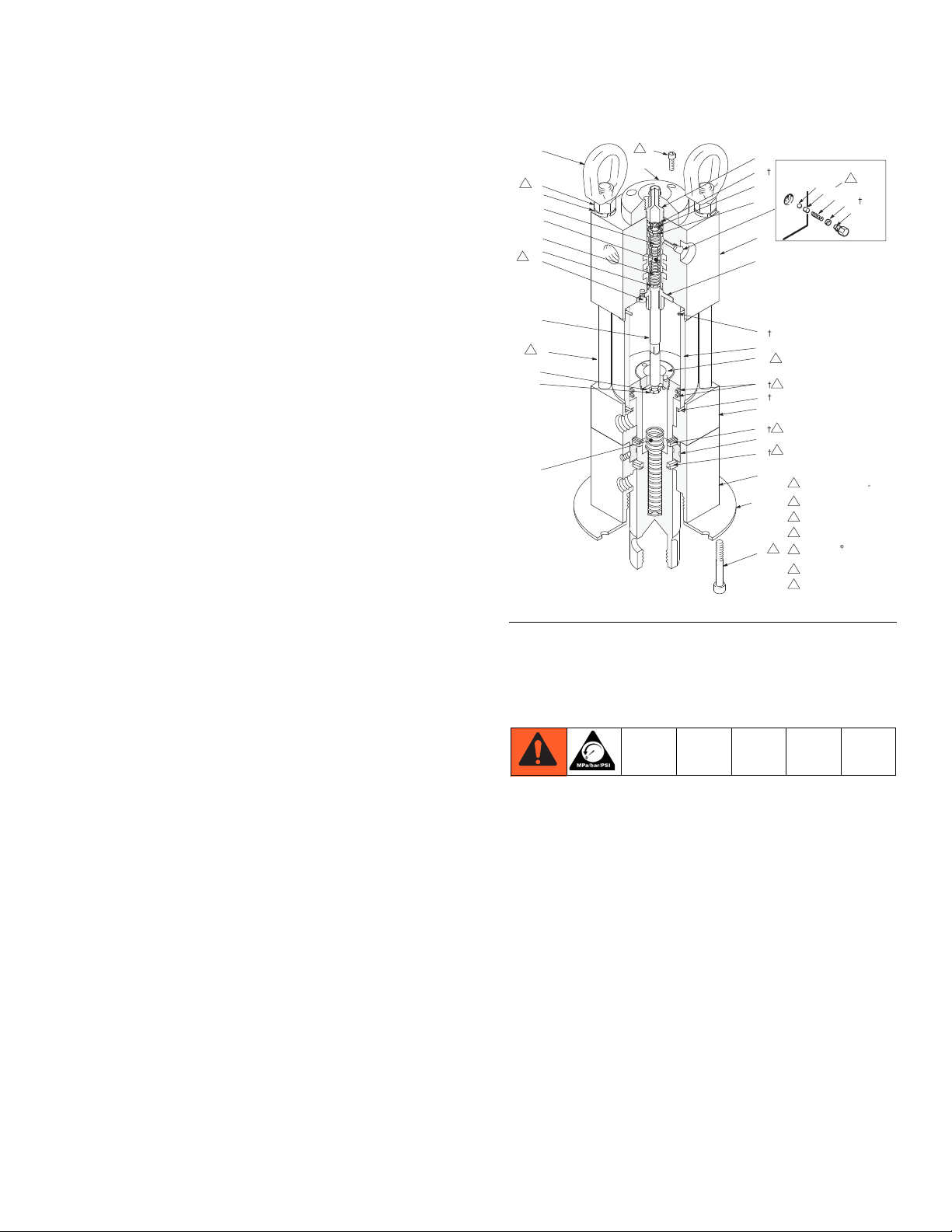
Repair
Repair
Refer to Parts Drawing on page 15 unless otherwise
specified.
NOTE:
• Spool valve Repair Kit 220457 is available to
replace the gaskets (29), spring retaining plugs (31),
springs (21), spool (38), trip rod (33) and piston stop
(37). The spool, plugs, and springs must be
replaced as a group.
• Clean all parts as you disassemble them, and
inspect for wear or damage. Replace parts as nec-
essary. Use Loctite
equivalent, when thread sealant is specified.
• Pump Repair Kit 236862 is available to replace the
gasket (29), o-rings (11, 12, 105 and 108) seals
(17), packing (107), and piston rings (15).
®
TL-242 thread sealant, or
Disassembly
Refer to Parts Drawing on page 15 unless otherwise specified.
To avoid serious injury, do not move this unit without the
use of lifting equipment. Keep the hoist attached for
steps 1 through 15.
1. Relieve the pressure (page 8), and stop the pump at
the bottom of its stroke.
NOTICE
Avoid getting dust or dirt in the motor during repair.
Cleanliness is essential when repairing a hydraulic
motor.
3. Place the hydraulic motor horizontally in a bench
vise at the pump adapter (42) and bottom cylinder
cap (43).
4. Remove the displacement pump with a strap
wrench.
5. Remove the cap screws (25) and the mounting plate
(46).
6. Remove the hydraulic motor from the vise.
7. Place the piston (110) flats in the vise.
8. Loosen, but do not remove the piston rod (44) with a
wrench.
9. Remove the piston (110) flats from the vise.
10. Place the motor vertically in the vise at the pump
adapter (42) and the bottom cylinder cap (43).
11. Remove the piston (110), ball (103), and seal (107).
NOTICE
To prevent damage to the spool (38) and the upper
housing (36), remove the detent parts (31, 21, 29, 30,
and 7) before removing the end cap (40).
NOTE: The socket screw (9), cap screws (22), and
retainer (32) are fastened with Loctite
may be used sparingly to soften the adhesive during disassembly.
12. Remove one detent assembly retaining plug (31),
spring (21), gasket (29), ball guide (30), and ball (7).
If the ball or other parts stick in the upper housing
(36), use a magnet to extract the parts. Do not allow
the parts to fall into the motor. Repeat the procedure
for the other detent assembly.
13. Unscrew the top and bottom flare nuts on the
hydraulic tube (49), and remove the tube. Allow the
oil to drain from the motor into a pan.
®
TL-242. Heat
2. Disconnect the displacement pump hoses. Disconnect the hydraulic hoses and plug all hydraulic connections and lines to prevent contamination.
308391J 11
14. Remove the socket screws (9), and remove the end
cap (40).
15. Remove the bolts (23), but do not remove the rods
(47).
Page 12

Repair
NOTICE
With the bolts removed, the assembly may separate
at the joints between the cylinder (35) and the upper
housing (36) and bottom cylinder cap (43),
16. Remove the stop plug (39) from the upper housing
(36). Pull the upper housing about 3 inches off the
cylinder (35). Shim the housing with 3/4 in. flat stock
to keep an opening. The cylinder can stay in the
lower housing (43).
17. Hold the trip rod (33) steady with a trip rod pliers
(P/N 207579) on the rod, and remove the top hex
nut (16) from the trip rod.
18. Remove the upper housing (36). Remove the valve
spool (38) from the upper housing (36). Save the
spring collars (41), the springs (34), and the parts
remaining inside the upper housing.
19. Inspect the bore in the upper housing (36) and the
outside diameter of the valve spool (38) for wear.
Replace parts if damaged. Inspect the trip rod (33)
above the shoulder for damage. There must be no
reduction in diameter.
20. Pull the trip rod and piston rod (44) from the lower
housing (43) and cylinder (35).
21. The seals (17) must be replaced if they are leaking.
Remove seals from adapter (42).
22. Perform steps 23 and 24 if parts inspected in step
19 are damaged.
23. Place the piston rod (44) in a vise; tighten the vise
on the flats of the piston rod. Use a spanner wrench
to remove the retainer (32). Remove the trip rod (33)
from the piston rod (44).
24. Remove the trip rod nut (10) and piston stop (37). If
the piston rod is replaced, remove the compression
springs (18), and compression rings (15) to use the
new piston rod.
Reassembly
Refer to FIG. 4 for the following instructions.
tom cylinder cap (43). Ensure all fluid ports are facing the same direction.
2. Install the piston rod (44) into the pump adapter (42)
and the bottom cylinder cap (43). Lubricate the piston rings (15) and install the piston rod (44) with the
openings on the rings opposed 180°.
3. Only perform steps 4 and 5 if steps 23 and 24 of
Disassembly were performed.
4. Install the compression spring (18) inside the piston
rod. Install the trip rod nut (10) and piston stop (37)
on the trip rod (33).
5. Install the trip rod (33) in the piston rod (44). Apply
thread sealant to the retainer (32). With the piston
flat in a vise, tighten the retainer until it is flush or
below the piston surface. This is important to prevent the retainer from backing out during operation
and damaging the motor.
6. Install the o-ring (12) on cylinder (35). Install the cylinder over the piston and rings.
7. Install the upper housing (36). Install a 3/4 inch flat
stock shim between the upper housing and the cylinder. Install the trip rod guide (41), the spring (34),
valve spool (38), and the remaining parts from the
inside of the upper housing. See Parts Drawing,
page 15,
8. Holding the trip rod (33) steady with a trip rod pliers
on the rod, and install the top hex nut (16) on the trip
rod.
9. Replace the o-ring (11) on the stop plug (39). Install
the stop plug in the upper housing (36).
10. Install tie rods (47) and bolts (23); hand tighten.
11. Install the two lock nuts (5) and washers (6).
12. Apply thread sealant to the socket screws (9). Install
the end cap (40) with the socket screws.
NOTICE
To avoid damaging the internal parts, install detent
parts (31, 21, 29, 30, and 7) after install the end cap
(40).
1. Place the pump adapter (42) in a vise. Grease the
new seal (17) from the repair kit. Install a seal in the
pump adapter (42) with the lip facings down. Install
the rod guide (45) and install the second seal with
the lip facing up in the pump adapter. Install the bot-
12 308391J
13. Install one detent assembly; retaining plug (31),
spring (21), gasket (29), ball guide (30), and ball (7).
Repeat for the other detent assembly.
Page 13
Repair
5
22
33
18
16
41
50
12
15
12
17
42
47
25
Lips must face
up toward top of motor
Rings must be positioned
with joints opposed 180
38
31
30
7
41
Apply Loctite TL–242
thread sealant to threads
43
Torque to
70–80 ft–lb (95–108 N.m)
1
4
5
2
1
2
6
4
6
Concave surface faces ball
6
37
10
34
34 36
9
7
7
Torque to
120–130 ft–lb (163–176 N.m)
17
3
Lips must face down toward bottom of pump
3
4
5
29
21
46
32
40
11
39
5
35
45
5
14. Align the tie rods (47) and bolts (23) and torque to
70 to 80 ft-lbs (95 to 108 N.m). Install eyelet (26)
Attach hoist to the eyelet.
15. Screw the top and bottom flare nuts on the hydraulic
tube (49), and install the tube.
16. Place the motor horizontally in a vise at the pump
adapter (42) and the bottom cylinder cap (43).
17. Apply thread sealant to the threads of the piston
(110) and install the piston, ball (103), and the seal
(107) with the lips facing up.
18. Remove the hydraulic motor from the vise.
19. Place the piston (110) flats in a vise.
20. Tighten the piston rod (44) with a wrench.
21. Remove the piston from the vise.
22. Place the pump horizontally in the vise.
23. Install the displacement pump with a strap wrench.
26
24. Remove the hydraulic motor from the bench vise.
25. Unplug all hydraulic connections and lines and connect the hydraulic hoses. Connect the displacement
pump hoses.
26. Flush the displacement pump if possible. Relieve
the pressure (page 8)
308391J 13
FIG. 4
Intake Valve
Refer to FIG. 5 for the following instructions.
1. Relieve the pressure, see page 8.
2. Unscrew the valve body (112). Remove the o-ring
(105), ball (104), and retainer (113).
3. Inspect the parts for wear or damage. If the ball is
nicked, replace it. Reassemble, using grease on the
male threads.
Page 14

Repair
104
112
105
111
107
113
1
108
Displacement Pump
Refer to FIG. 5 for the following instructions.
NOTE: Clean and inspect all parts for wear of damage
as you disassemble them. Replace parts as needed. For
the best results, always replace all the o-rings and packings when you disassemble the pump.
1. Relieve the pressure, see page 8.
2. Remove the piston (110). Follow steps 1 through 11
of Disassembly (page 11).
3. Carefully inspect the smooth inner surface of the
cylinder (111) for scoring or irregular surfaces. Such
damage causes premature seal wear and leaking.
Replace the parts as needed.
4. Grease the new piston seal and install with the lips
facing up.
5. Reconnect the reciprocator and displacement pump
as described in steps 16 through 26 of Reassembly,
page 12.
FIG. 5
14 308391J
Page 15

Parts
29
See the repair section for important
torque and lubrication notes
Rings must be positioned
with joints opposed 180
Torque to
70–80 ft–lb (95–108 N.m)
1
2
9
6
27
26
28
13
49
47
5
14
19
45
17
24
17
43
35
12
12
40
23
39
32
37
10
15
15
18
44
25
46
11
16
41
34
38
34
41
50
33
7
30
21
31
19
22
36
3
2
2
42
1
1
Torque to
120–130 ft–lb (163–176 N.m)
3
4
5
4
5
Lips face up
Lips face down
56
54
Parts
308391J 15
Page 16

Parts
Part No./Description
Ref. Part Description Qty.
5 100127 NUT, mscr, hex, 5/8-11 unc-2B 2
6 100128 LOCKWASHER, spring, 5/8” 4
7 101701 BALL, 1/4 inch dia 2
8 101754 PLUG, pipe, 3/8 npt(f) 1
9 101864 CAPSCREW, soc hd, 5/16-18 x 1
inch
10 103450 NUT, hex, self locking, 5/16-18 1
11† 104093 O-RING, nitrile rubber 1
12† 104095 O-RING, nitrile rubber 2
13 104098 TEE, tube, for 3/4 in. (19 mm) tube 1
14 104099 ELBOW, 90°, for 3/4 in (19 mm)
tube
15† 104103 RING, piston, compression 2
16 104105 NUT, hex lock, 1/4-20 1
17† 104203 SEAL, v-block, polyurethane 2
18 104664 SPRING, compression 1
19 105429 NUT, seal, 3/4-14 npt 2
20 105430 NUT, seal, 1 in. npt 1
21 108522 SPRING, helical compression 2
22 108538 SCREW, soc flat hd, self locking,
1/4-20 x 1/2 in.
23 109203 BOLT, hex hd 2
24 110064 PLUG, pipe, vented 1
25 112570 SCREW, cap, soc hd 4
26 112571 NUT, eye 2
27 112573 ADAPTER, pipe, female 1
28 112574 UNION, swivel 1
29† 150111 GASKET, plug 2
30 167210 GUIDE, ball 2
31 167431 PLUG, spring retaining 2
32 171398 RETAINER 1
33 171407 ROD, trip 1
34 171411 SPRING, compression 2
35 171412 CYLINDER 1
36 172814 HOUSING, upper 1
37 181243 STOP, piston 1
38 181874 SPOOL, valve 1
39 183252 PLUG, stop 1
40 183290 CAP, end 1
41 183659 GUIDE, trip, shaft 2
42 189714 ADAPTER, pump 1
43 189715 CAP, cylinder, bottom 1
44 189716 PISTON, rod, hydraulic 1
45 189717 GUIDE, rod 1
46 189718 PLATE, mounting 1
47 189719 ROD, tie 2
48 189720 LABEL, identification 1
49 210108 TUBE 1
50 210292 BEARING and GUIDE 1
54 116343 SCREW, ground 1
56▲ 290331 LABEL, instruction, English 1
German (Part No. 290396)
French (Part No. 290397)
Spanish (Part No. 290398)
† Parts included in Pump Repair Kit 236862 (purchase
3
1
3
separately).
▲ Replacement Danger and Warning labels, tags, and
cards are available at no cost. Also available in the
following languages:
16 308391J
Page 17

Parts
104
110
113
108
112
114
101
111
107
105
103
03845
Ref. Part Description Qty.
101 236752 RECIPROCATOR, hydra,
Power-Star
103 101178 BALL, metallic 1
104 108001 BALL, metallic, sst 1
105† 110828 PACKING, o-ring 1
107† 112565 SEAL, block vee 1
108† 166071 PACKING, o-ring 1
Ref. Part Description Qty.
110 189707 PISTON, fluid 1
1
111 189708 CYLINDER, pump 1
112 189709 VALVE, housing 1
113 189710 RETAINER, ball 1
114 189711 WASHER, piston 1
† Parts included in Pump Repair Kit 236862 (purchase
separately).
308391J 17
Page 18

Technical Data
30 in.
(762 mm)
7.0 in.
(177.8 mm)
8.0 in.
(203.2 mm)
.406 in. ( 10.31 mm) diameter (4);
for 3/8 in. screw
4.0 in.
(101.6 mm)
Technical Data
.
Power-Star
Fluid Ratio 1:1
Maximum Output Flow 12.0 gpm 45.4 lpm
Maximum Output Pressure 1500 psi 10.3 MPa, 103 bar
Maximum Input Flow
Maximum Hydraulic Fluid Input Pressure 1500 psi 10.3 MPa, 103 bar
Maximum Input Fluid Temperature 130°F 55°C
Pressure Reducing Adjustment Range 300-1500 psi 2.07 - 10.3 MPa, 20.7 - 103 bar
Weight 100lb 45.4 kg
Rod Seals Nitrile
Piston Seals Polyurethane
Displacement Pump Wetted Parts Iron, Steel, SST Nitrile, Polyurethane
Sound Pressure 78 dB(A)*
* Sound pressure reading taken with pump operating at 60 cycles per minute. Sound pressure measured per
CAGI-PNEUROP, 1971
Loctite® is a registered trademark of the Loctite Corporation.
™
US Metric
12.0 gpm
45.4 lpm
Dimensions
18 308391J
Page 19

Performance Chart
Technical Data
308391J 19
Page 20

Graco Standard Warranty
Graco warrants all equipment referenced in this document which is manufactured by Graco and bearing its name to be free from defects in
material and workmanship on the date of sale to the original purchaser for use. With the exception of any special, extended, or limited warranty
published by Graco, Graco will, for a period of twelve months from the date of sale, repair or replace any part of the equipment determined by
Graco to be defective. This warranty applies only when the equipment is installed, operated and maintained in accordance with Graco’s written
recommendations.
This warranty does not cover, and Graco shall not be liable for general wear and tear, or any malfunction, damage or wear caused by faulty
installation, misapplication, abrasion, corrosion, inadequate or improper maintenance, negligence, accident, tampering, or substitution of
non-Graco component parts. Nor shall Graco be liable for malfunction, damage or wear caused by the incompatibility of Graco equipment with
structures, accessories, equipment or materials not supplied by Graco, or the improper design, manufacture, installation, operation or
maintenance of structures, accessories, equipment or materials not supplied by Graco.
This warranty is conditioned upon the prepaid return of the equipment claimed to be defective to an authorized Graco distributor for verification of
the claimed defect. If the claimed defect is verified, Graco will repair or replace free of charge any defective parts. The equipment will be returned
to the original purchaser transportation prepaid. If inspection of the equipment does not disclose any defect in material or workmanship, repairs will
be made at a reasonable charge, which charges may include the costs of parts, labor, and transportation.
THIS WARRANTY IS EXCLUSIVE, AND IS IN LIEU OF ANY OTHER WARRANTIES, EXPRESS OR IMPLIED, INCLUDING BUT NOT LIMITED
TO WARRANTY OF MERCHANTABILITY OR WARRANTY OF FITNESS FOR A PARTICULAR PURPOSE.
Graco’s sole obligation and buyer’s sole remedy for any breach of warranty shall be as set forth above. The buyer agrees that no other remedy
(including, but not limited to, incidental or consequential damages for lost profits, lost sales, injury to person or property, or any other incidental or
consequential loss) shall be available. Any action for breach of warranty must be brought within two (2) years of the date of sale.
GRACO MAKES NO WARRANTY, AND DISCLAIMS ALL IMPLIED WARRANTIES OF MERCHANTABILITY AND FITNESS FOR A
PARTICULAR PURPOSE, IN CONNECTION WITH ACCESSORIES, EQUIPMENT, MATERIALS OR COMPONENTS SOLD BUT NOT
MANUFACTURED BY GRACO. These items sold, but not manufactured by Graco (such as electric motors, switches, hose, etc.), are subject to
the warranty, if any, of their manufacturer. Graco will provide purchaser with reasonable assistance in making any claim for breach of these
warranties.
In no event will Graco be liable for indirect, incidental, special or consequential damages resulting from Graco supplying equipment hereunder, or
the furnishing, performance, or use of any products or other goods sold hereto, whether due to a breach of contract, breach of warranty, the
negligence of Graco, or otherwise.
FOR GRACO CANADA CUSTOMERS
The Parties acknowledge that they have required that the present document, as well as all documents, notices and legal proceedings entered into,
given or instituted pursuant hereto or relating directly or indirectly hereto, be drawn up in English. Les parties reconnaissent avoir convenu que la
rédaction du présente document sera en Anglais, ainsi que tous documents, avis et procédures judiciaires exécutés, donnés ou intentés, à la suite
de ou en rapport, directement ou indirectement, avec les procédures concernées.
Graco Information
For the latest information about Graco products, visit www.graco.com.
TO PLACE AN ORDER, contact your Graco distributor or call to identify the nearest distributor.
Phone: 612-623-6928 or Toll Free: 1-800-533-9655, Fax: 612-378-3590
All written and visual data contained in this document reflects the latest product information available at the time of publication.
GRACO INC. AND SUBSIDIARIES • P.O. BOX 1441 • MINNEAPOLIS MN 55440-1441 • USA
Copyright 1994, Graco Inc. All Graco manufacturing locations are registered to ISO 9001.
Graco reserves the right to make changes at any time without notice.
For patent information, see www.graco.com/patents.
Original instructions. This manual contains English. MM 308391
Graco Headquarters: Minneapolis
International Offices: Belgium, China, Japan, Korea
www.graco.com
Revised February 2014
 Loading...