

Page 1
Operating Instructions
309388
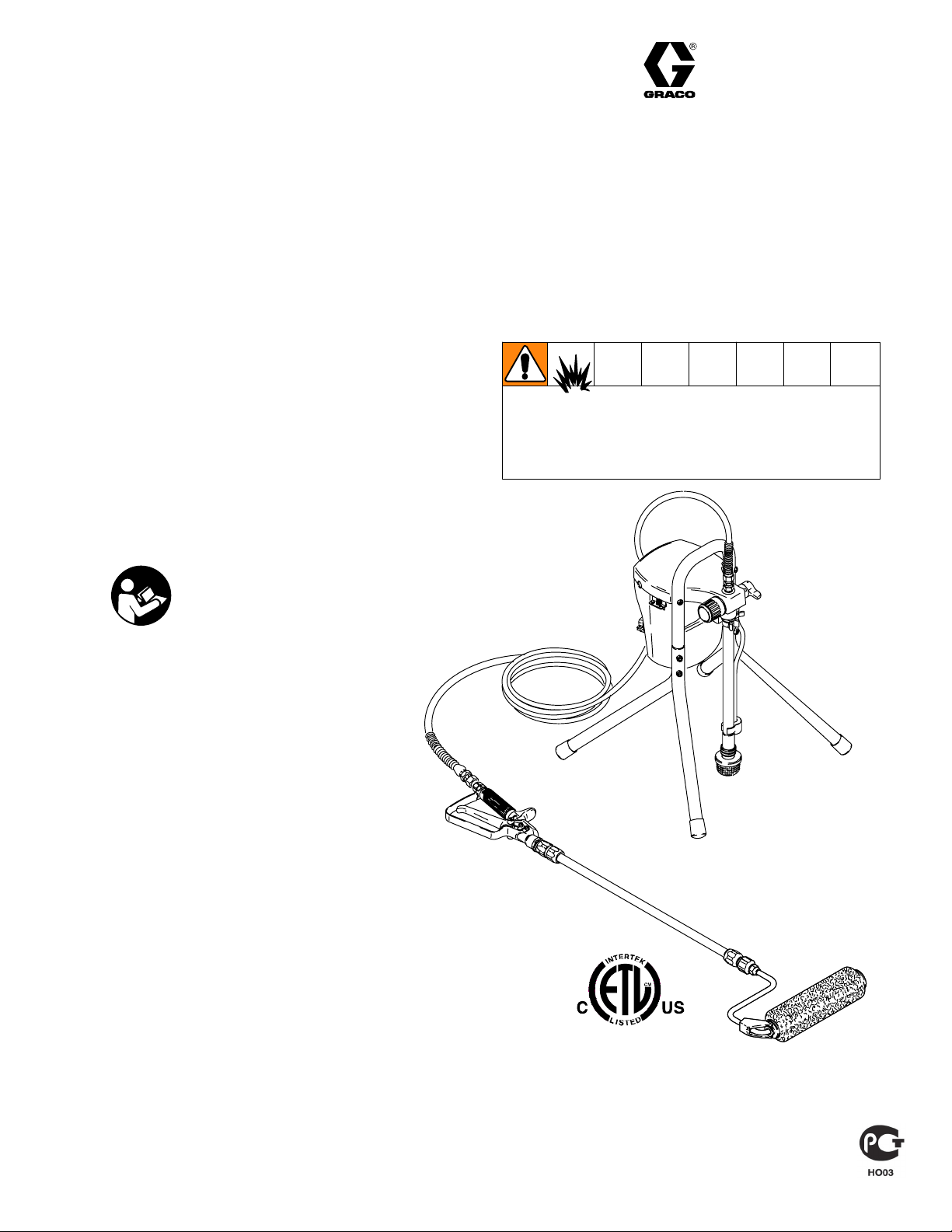
150 RPX Pressure Roller
and Spray System
– For roller and portable spray application
of architectural paints and coatings –
Model 233687, Series B
2800 psi (193 bar, 19 MPa) Maximum Working Pressure*
* The best operating pressure is the lowest pressure that provides an even paint supply to the roller and
typically does not exceed 300 psi (2.1 MPa, 21 bar).
Also Includes: ContractortIn–line Valve 244161
and Pressure Roller 244279
D 20 in. (50 cm) heavy-duty extension
D 3/16 in. x 25 ft DuraFlext hose
D 9 in. (23 cm) roller frame
D 1/2 in. (13 mm) nap roller cover
Use water based or mineral spirit–type material
only. Do not use materials having flash points
lower than 70_ (21_). For information about
your material request MSDS from distributor or
retailer.
Rev. J
Important Safety Instructions
Read all warnings and instructions in this
manual. Save these instructions.
Table of Contents
Warnings 2. . . . . . . . . . . . . . . . . . . . . . . . .
Pressure Relief 6. . . . . . . . . . . . . . . . . . .
Component Identification 7. . . . . . . . .
Setup 8. . . . . . . . . . . . . . . . . . . . . . . . . . . . .
Priming 9. . . . . . . . . . . . . . . . . . . . . . . . . .
Operation 13. . . . . . . . . . . . . . . . . . . . . . . .
Cleanup 17. . . . . . . . . . . . . . . . . . . . . . . . .
Trouble Shooting 28. . . . . . . . . . . . . . . .
Service 31. . . . . . . . . . . . . . . . . . . . . . . . . .
Parts 36. . . . . . . . . . . . . . . . . . . . . . . . . . . .
Technical Information 42. . . . . . . . . . .
Graco Warranty 44. . . . . . . . . . . . . . . . . .
Graco Phone Number 44. . . . . . . . . . .
ti8468a
GRACO INC.ąP.O. BOX 1441ąMINNEAPOLIS, MNą55440-1441
ECOPYRIGHT 2001, GRACO INC.
Graco Inc. is registered to I.S. EN ISO 9001
Page 2
Specifications
This equipment is not intended for use with flammable or combustible materials used in places such as
cabinet shops or other “factory” or fixed locations. If you intend to use this equipment in this type of
application, you must comply with NFPA 33 and OSHA requirements for the use of flammable and
combustible materials.
The following are general warnings related to the setup, use, grounding, maintenance, and repair of this equipment.
Additional, more specific warnings may be found throughout the body of this manual where applicable. Symbols
appearing in the body of the manual refer to these general warnings. When these symbols appear throughout the
manual, refer back to these pages for a description of the specific hazard.
WARNING
FIRE AND EXPLOSION HAZARD
Flammable fumes, such as solvent and paint fumes, in work area can ignite or explode. To help
prevent fire and explosion:
D Use equipment only in well ventilated area.
D Eliminate all ignition sources; such as pilot lights, cigarettes, portable electric lamps, and plastic
drop clothes (potential static arc).
D Sprayer generates sparks. When flammable liquid is used in or near sprayer or for flushing or
cleaning, keep sprayer at least 20 ft (6 m) away from explosive vapors.
D Keep work area free of debris, including solvent, rags and gasoline.
D Do not plug or unplug power cords or turn lights on or off when flammable fumes are present.
D Ground equipment and conductive objects in work area. Read Grounding instructions.
D If there is static sparking or you feel a shock, stop operating immediately. Do not use equipment
until you identify and correct the problem.
D Keep a fire extinguisher in the work area.
ELECTRIC SHOCK HAZARD
Improper grounding, setup, or usage of the system can cause electric shock.
D Turn off and disconnect power cord before servicing equipment.
D Use only grounded electrical outlets
D Use only 3–wire extension cords.
D Ensure ground prongs are intact on sprayer and extension cords.
D Do not expose to rain. Store indoors.
2 309388
Page 3
INSTRUCTIONS
SKIN INJECTION HAZARD
High pressure fluid from gun, hose leaks, or ruptured components will pierce skin. This may look like
just a cut, but it is a serious injury that can result in amputation. Get immediate surgical attention.
D Do not point gun at anyone or any part of the body.
D Do not put your hand over the spray tip.
D Do not stop or deflect leaks with your hand, body, glove, or rag.
D Engage trigger lock when not spraying.
D Follow Pressure Relief Procedure in this manual, when you stop spraying and before cleaning,
checking or servicing equipment.
EQUIPMENT MISUSE HAZARD
Misuse can cause death or serious injury.
D Do not exceed the maximum working pressure or temperature rating of the lowest rated system
component. Read Technical Data in all equipment manuals.
D Use fluids and solvents that are compatible with equipment wetted parts. Read Technical Data in
all equipment manuals. Read fluid and solvent manufacturer’s warnings. For complete information
about your material, request MSDS from distributor or retailer.
D Check equipment daily. Repair or replace worn or damaged parts immediately with genuine Graco
replacement parts only.
D Do not alter or modify equipment.
D Use equipment only for its intended purpose. Call your Graco distributor for information.
D Route hoses and cables away from traffic areas, sharp edges, moving parts and hot surfaces.
D Do not kink or overbend hoses or use hoses to pull equipment.
D Keep children and animals away from work area.
D Do not operate the unit when fatigured or under the influence of drugs or alcohol.
D Comply with all applicable safety regulations.
PRESSURIZED ALUMINUM PARTS HAZARD
Do not use 1,1,1-trichloroethane, methylene chloride, other halogenated hydrocarbon solvents or
fluids containing such solvents in this equipment. Such use could result in a serious chemical reaction,
with the possibility of explosion, which could cause death, serious injury and/or substantial property
damage.
TOXIC FLUID HAZARD
Toxic fluid or fumes can cause serious injury or death if splashed in the eyes or on skin, inhaled, or
swallowed.
D Read MSDS’s to know the specific hazards of the fluids you are using.
D Store hazardous fluid in approved containers and dispose of it according to all applicable guide-
lines.
PERSONAL PROTECTIVE EQUIPMENT
You must wear appropriate protective equipment when operating, servicing, or when in the operating
area of the equipment to help protect you from serious injury, including eye injury, inhalation of toxic
fumes, burns, and hearing loss. This equipment includes, but is not limited to:
D Protective eye wear.
D Clothing and respirator as recommended by the fluid and solvent manufacturer.
D Gloves.
D Hearing protection.
3309388
Page 4

Grounding and Electric Requirements
The sprayer must be grounded. Grounding reduces the risk of static
and electric shock by providing and escape wire for the electrical
current due to static build up or in the event of a short circuit.
ti5572a
ti3001b
D The sprayer requires a 120V AC, 60 Hz, 15A circuit
with grounding receptacle. Never use an outlet that is
not grounded or an adapter.
D Do not use the sprayer if the electrical cord has a damaged
ground prong. Only use an extension cord with an undamaged,
3–prong plug.
D Recommended extension cords for use with this sprayer:
D 25 ft (7.6 m) 18 AWG
D 50 ft (15.2 m) 16 AWG
D 100 ft (30.5 m) 14 AWG
D 150 ft. (45.7 m) 12 AWG
Smaller gauge or longer extension cords may reduce sprayer
performance.
4 309388
D Ground sprayer gun through connection to a
properly grounded fluid hose and pump.
D Ground fluid supply container. Follow local code.
Page 5
Grounding and Electric Requirements
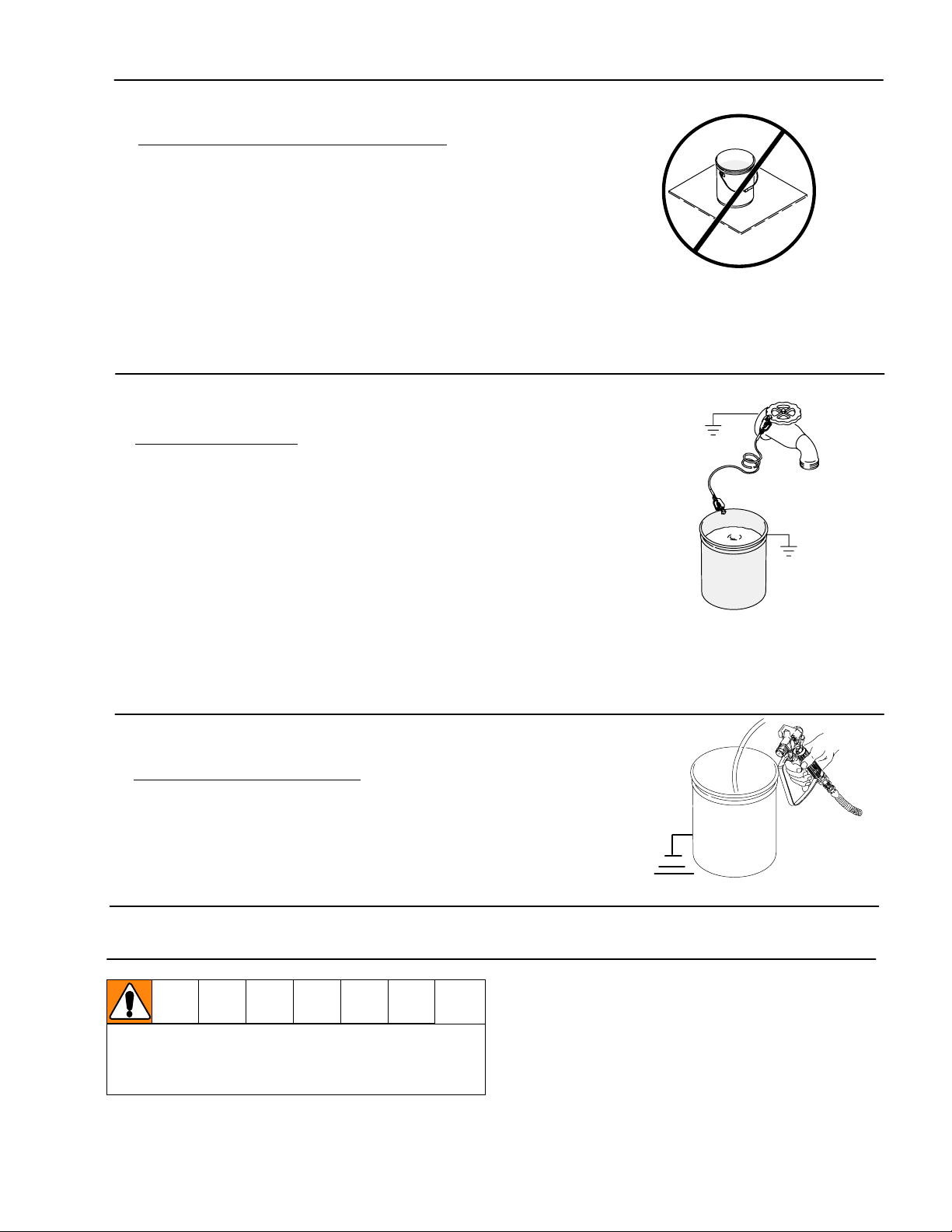
D Ground solvent pails used when flushing. Follow local code. Use
only conductive, metal pails, placed on a grounded surface such as
concrete. Do not place the pail on a non–conductive surface such
as paper or cardboard, which interrupts the grounding continuity.
D Ground the metal pail by connecting a ground wire to the
pail by clamping one end to pail and the other end to
ground such as as water pipe.
ti5850a
D Maintain grounding continuity when flushing or
relieving pressure by holding metal part of spray gun
firmly to side of a grounded metal pail, then trigger gun.
Thermal Overload
To reduce risk of injury from motor staring
unexpectedly when it cools, always turn power
switch OFF if motor shuts down.
ti5851a
D Motor has a thermal overload switch
to shut itself down if overheated.
5309388
Page 6
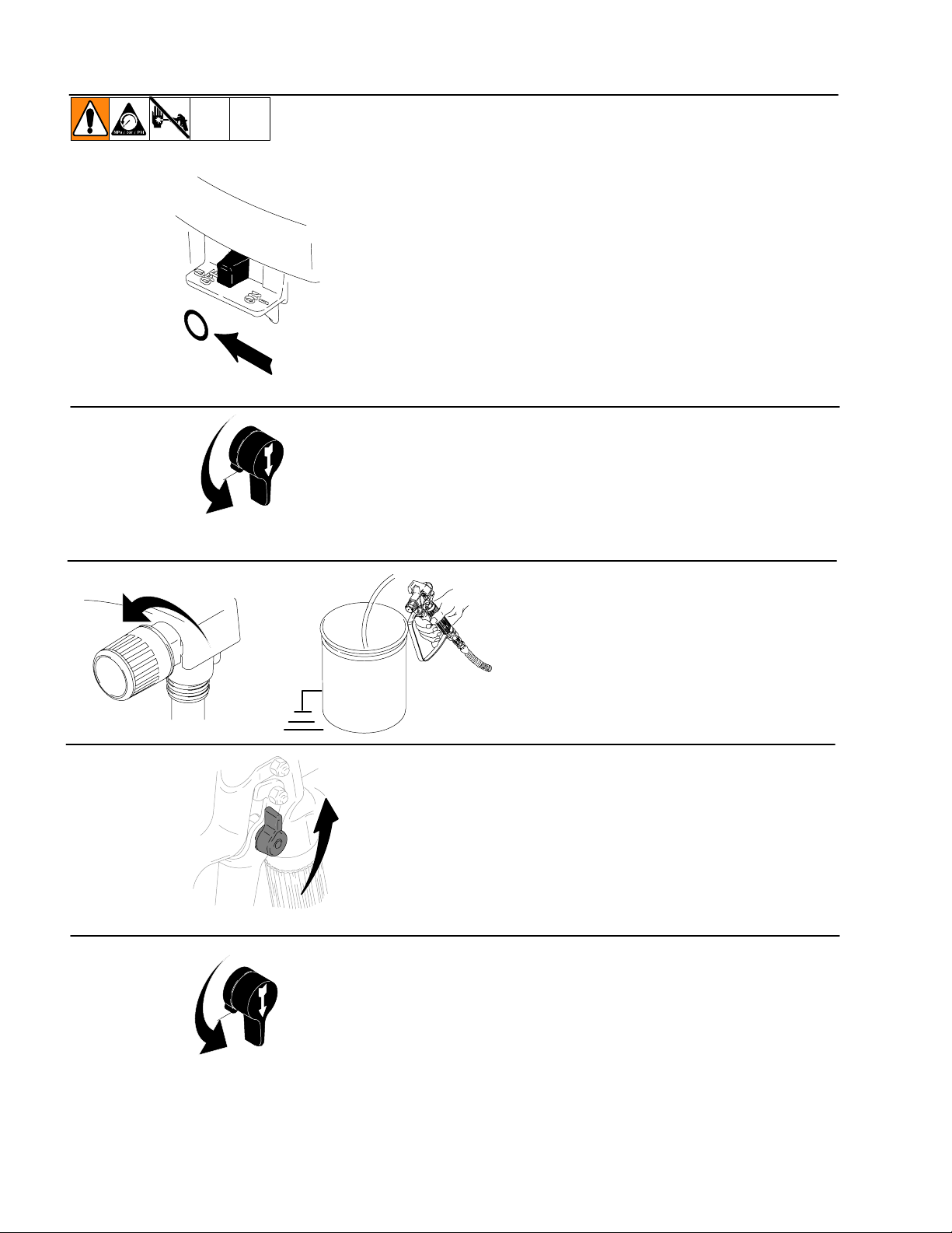
Pressure Relief Procedure
1. Turn power switch OFF and unplug power
cord.
2. Turn Spray–Prime/Drain valve to
PRIME/DRAIN to relieve pressure.
PRIME
3. Turn pressure to lowest setting. Hold metal
part of gun firmly to a grounded metal pail.
Trigger gun to relieve pressure.
4. Engage trigger lock.
D Leave Spray–Prime/Drain valve in PRIME/
DRAIN position until you are ready to spray
again.
6 309388
PRIME
D If you suspect the spray tip is clogged or
that pressure has not been fully relieved
after following the above steps, VERY
SLOWLY loosen tip guard retaining nut or
hose end coupling to relieve pressure
gradually. Then loosen completely. Clear
hose or tip obstruction.
Page 7
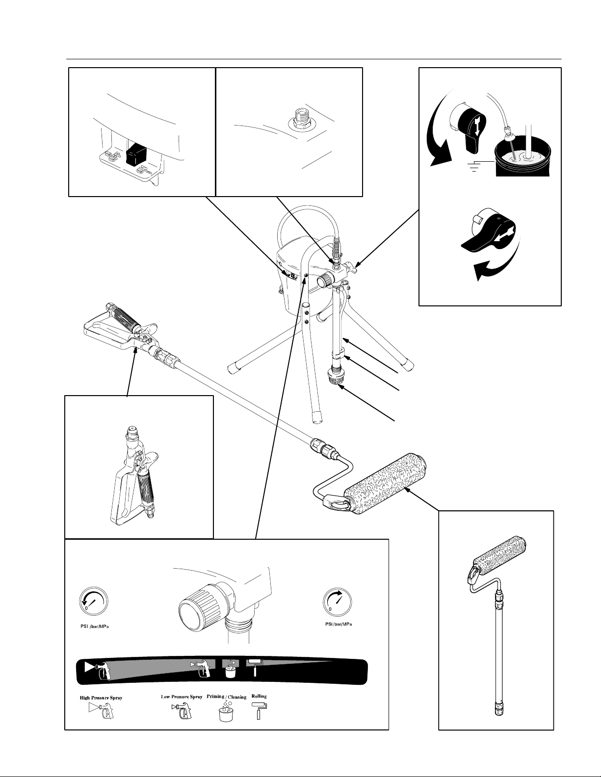
Component Identification
Power Switch
Fluid Outlet Fitting
Spray/Prime Valve
Prime/drain position
Paint position
Contractort In–line Valve
Pressure Control Knob
Prime Tube
Suction Tube
Inlet Screen
Pressure Roller
7309388
Page 8
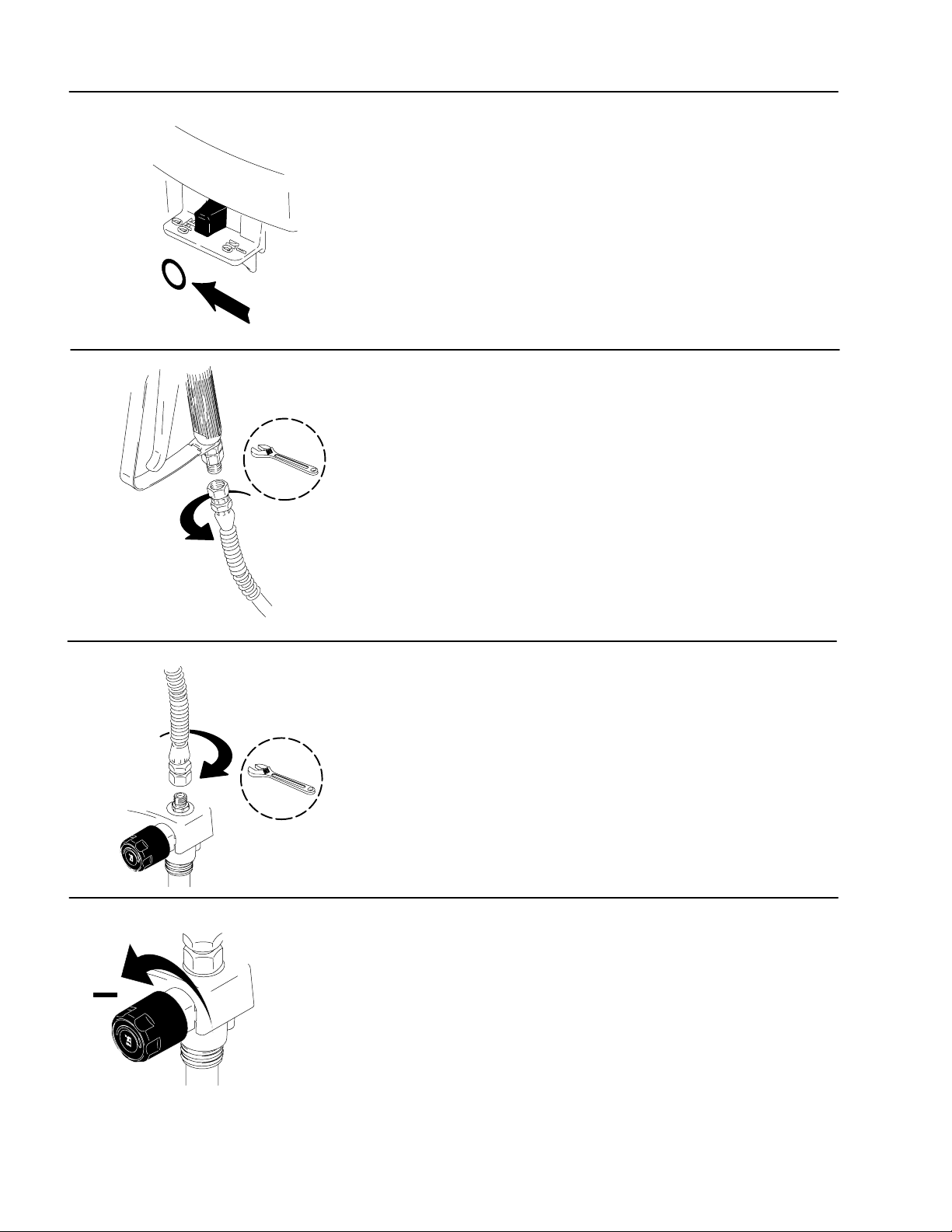
Setup
1. Turn power switch OFF.
2. Connect one end of grounded fluid hose
to the In–line Valve. Use a wrench to
tighten.
NOTE: The Contractort In–line Valve
can be used as an airless spray gun
for small jobs by attaching a Handtitet Guard and RAC5 Switchtip.
For larger jobs the sprayer can be
used for airless spraying by attaching
an airless spray gun rated at 2800 psi
(193 bar, 19 MPa) Maximum Working
Pressure or higher.
3. Connect other end of hose to sprayer
fluid outlet fitting. Use a wrench to
tighten.
4. Turn pressure control knob all the way left
(counterclockwise) to minimum pressure.
8 309388
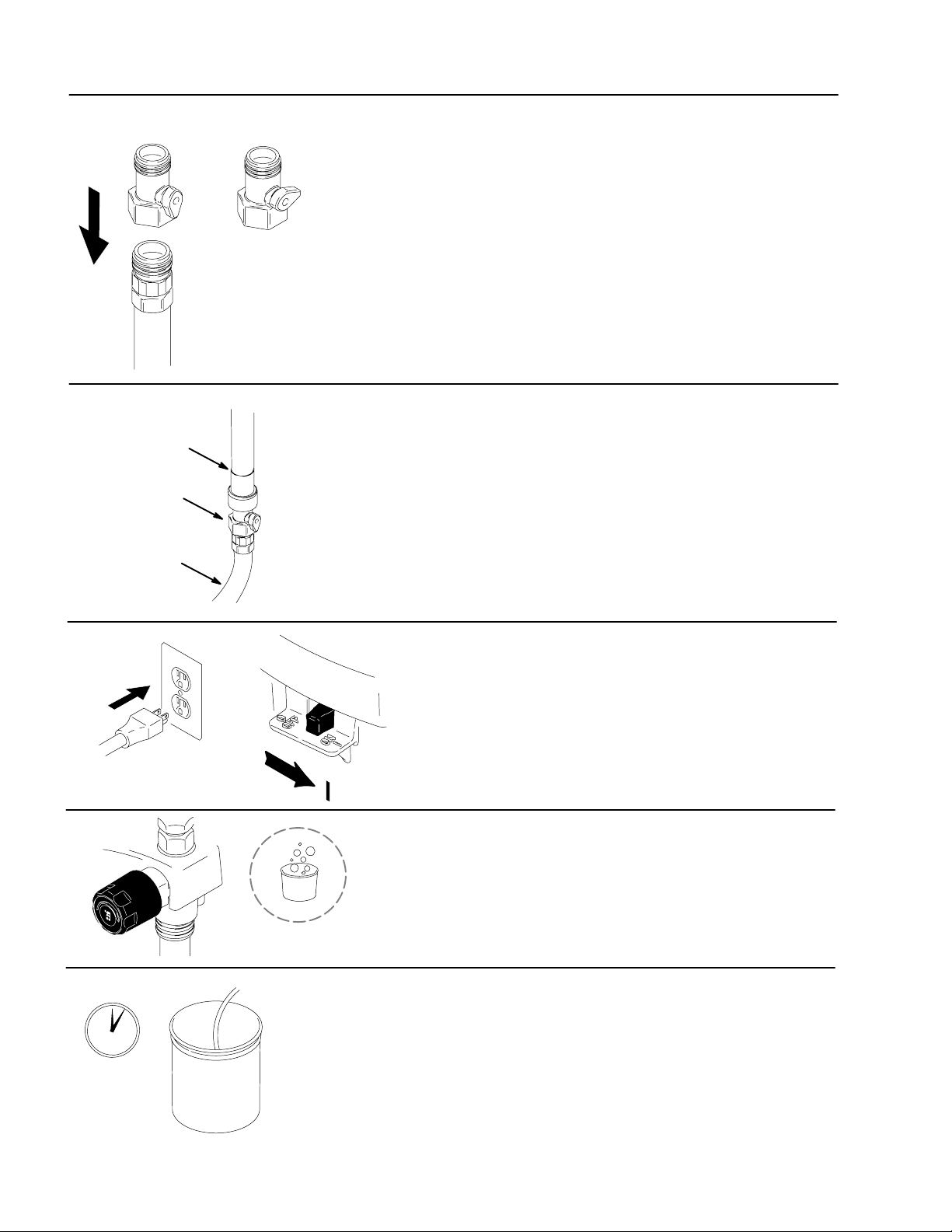
Page 9
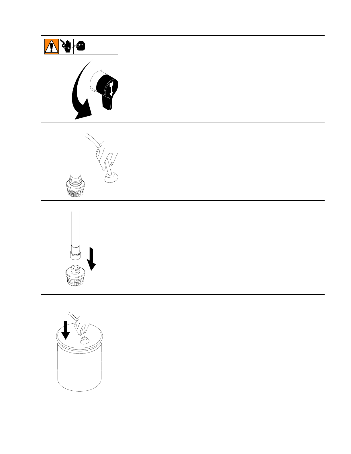
Priming – For flushing factory or storage fluid and loading pump with water
1. Turn Spray/Prime valve to PRIME.
2. Separate the (smaller) prime tube from
the (larger) suction tube.
suction
tube
prime
tube
prime tube
WASTE
3. Unscrew inlet screen from suction tube.
4. Place prime tube in waste pail.
9309388
Page 10
Priming – For flushing factory or storage fluid and loading pump with water
Power Flush attachment
open closed
garden hose
suction tube
Power Flush
attachment
garden hose
(turn on)
5. Screw Power Flush attachment (included with
sprayer) onto garden hose and OPEN Power
Flush attachment.
6. Screw garden hose and Power Flush
attachment onto suction tube and turn
ON garden hose.
30 to 60
seconds
7. Plug sprayer in to grounded outlet and turn
power switch ON.
8. Align arrow on sprayer pressure
control knob to (bucket symbol) until
the pump starts.
9. Let water flow out of prime tube into waste
pail for 30 to 60 seconds. Water flowing
out of prime tube indicates pump is primed
with water.
WASTE
10 309388
Page 11
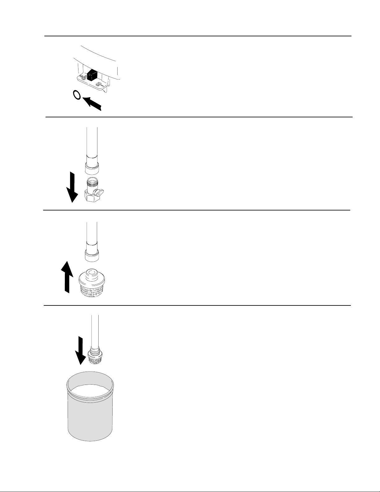
Priming – For flushing water and loading pump and hose with paint
1. Turn power switch OFF.
2. Turn Power Flush to closed position and
garden hose OFF. Unscrew Power Flush
attachment from suction hose.
3. Screw inlet screen onto suction tube.
4. Submerge suction tube in paint.
PAINT
11309388
Page 12
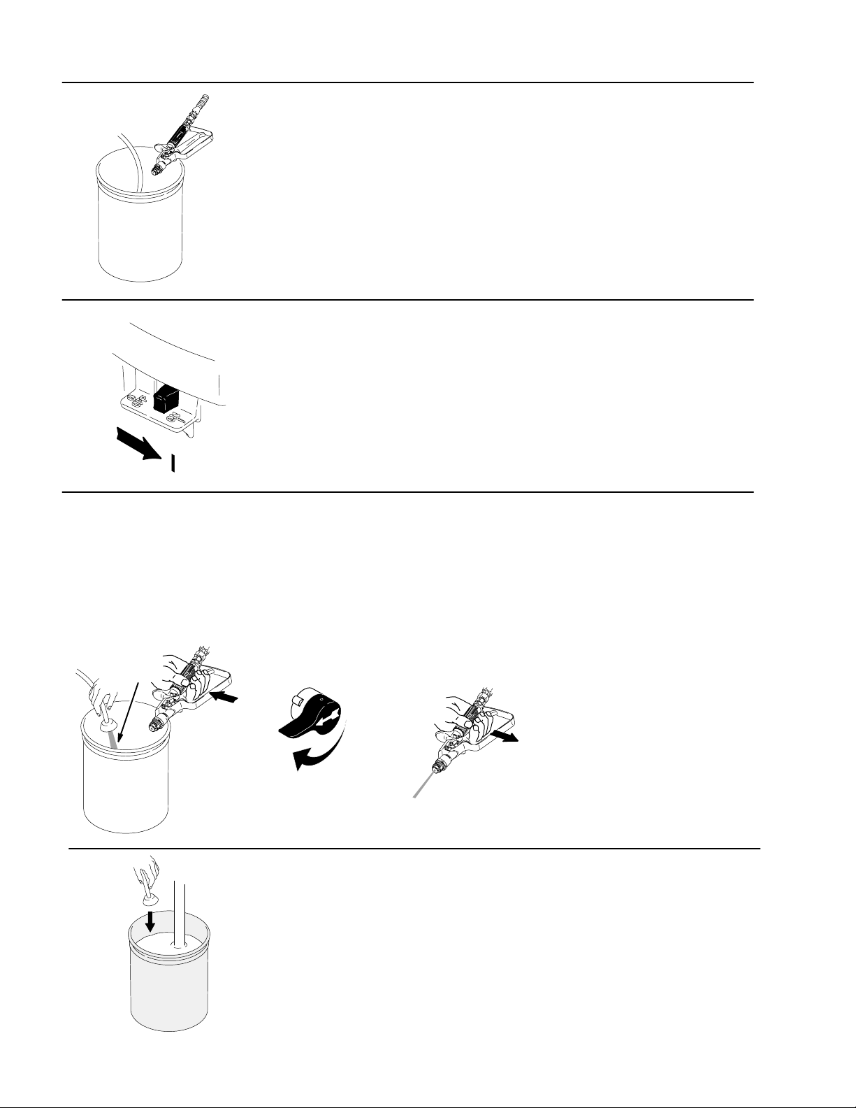
Priming – For flushing water and loading pump and hose with paint
5. Point In–line Valve into waste pail.
WASTE
6. Turn power switch ON.
paint
WASTE
7. When paint starts to come out of prime tube,
pull and hold In–line Valve trigger and turn
Spray/Prime valve to spray. When paint
comes out of In–line Valve release trigger.
NOTE: The motor stopping indicates the
pump and hose are primed with paint.
Release trigger
SPRAY
8. Transfer prime tube to paint pail.
12 309388
PAINT
Page 13
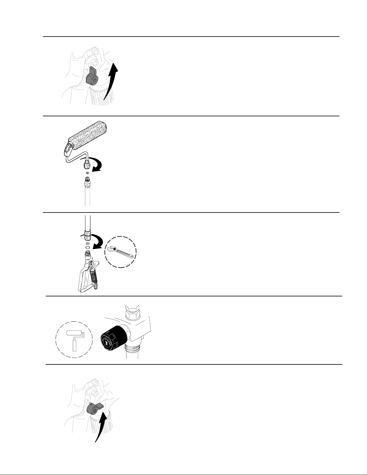
Operation
1. Engage the In–line Valve safety latch.
2. Firmly tighten pressure roller to 20” extension.
3. Attach pressure roller assembly to In–line
Valve. Use a wrench to tighten.
4. Turn pressure control knob to roller symbol.
5. Disengage In–line Valve safety latch.
Trigger In–line Valve and roll the surface
until paint comes to roller.
NOTE: Trigger the In–line Valve briefly
only when you need more paint. Determine
how often you must trigger the gun to
maintain an even paint supply to the roller.
13309388
Page 14
Operation
6. Increase pump pressure only if triggering
7. Whenever you stop painting, relieve
In–line Valve cannot supply enough paint
for your rolling speed.
pressure, page 6, and elevate roller
end of extension tube to prevent
paint from draining out.
Flush the pump, In–line Valve and
pressure roller immediately after
each use to prevent paint from drying
in the pressure roller and damaging
it. Cleanup page 17.
14 309388
Page 15

Rolling Techniques
1. Rolling vertically, roll out the letter “M”.
2. Cross roll, horizontally, to spread the
paint.
3. Finish with light vertical strokes until the
entire area has been evenly covered.
15309388
Page 16

Ceilings, Woodwork and Walls
1. Ceilings: Using a paint brush, apply a
starting row of paint approximately the
width of your brush where the walls and
ceiling meet.
2. With the roller, apply paint to the ceiling,
working the short way of the room and
applying as wide a strip as possible.
1. Woodwork & Walls: Using a brush,
paint woodwork first. Apply a starting
row of paint approximately the width of
the paint brush around the woodwork and
where the walls meet the ceiling.
2. With the roller, apply paint to the walls,
following the Roller Techniques described on
page 15.
16 309388
Page 17

Cleanup
Leave the roller assembly attached to the In–line Valve for this procedure.
1. Relieve the pressure. Turn power switch
OFF.
2. Remove roller cover and diffuser from roller frame
as follows:
a. Using your thumb, slide clip down and release
end caps, diffuser, and roller cover into a pail.
b. Remove roller cover from diffuser.
c. Pull end caps off diffuser.
17309388
Page 18

Solvent
Paint
Cleanup (continued)
3. Clean roller cover, caps and diffuser with water or a
compatible solvent for non–water–based materials.
4. Place roller frame in paint pail. Be sure the holes in the
frame are facing inside the paint pail.
Solvent
5. Place suction tube in bucket of water or compatible
solvent for non–water–based materials.
6. Turn pressure control knob to roller symbol.
18 309388
Page 19

Cleanup (continued)
7. Turn power switch ON.
8. Trigger In–line Valve.
9. Turn Spray/Prime valve to SPRAY.
Solvent
10. Continue to trigger In–line Valve until flushing
fluid begins to dilute paint. Then release
In–line Valve trigger.
11. Place roller frame in another bucket.
If you are flushing a non–water–based fluid, flush
until fluid coming out of roller frame is clear. Proceed
to page 25, Cleanup–Cleaning Contractort In–line
Valve Filter.
If water–based, follow Power Flushing procedure,
page 20.
12. Relieve pressure, page 6. Turn power
switch OFF.
19309388
Page 20

Cleanup – Power Flushing After Spraying Water–based Paint
1. Relieve pressure, page 6. Turn power switch OFF.
Power Flush attachment
2. Screw Power Flush attachment onto garden hose.
close
open
garden hose
closed
3. Turn lever to close Power Flush attachment.
4. Unscrew inlet screen from suction tube and place in
waste pail.
inlet screen
20 309388
WASTE
Page 21

Cleanup – Power Flushing After Spraying Water–based Paint – (continued)
5. Connect garden hose to suction tube with Power Flush
attachment. Leave prime tube in waste pail.
Suction tube
Power Flush attachment
garden hose
6. Turn lever to open Power Flush attachment. Turn on
garden hose.
open
7. Align arrow on sprayer with bucket symbol on Pressure
Knob.
8. Turn power switch ON.
21309388
Page 22

Cleanup – Power Flushing After Spraying Water–based Paint – (continued)
9. Place roller frame in waste pail and trigger In–line
Valve. Be sure the holes of the roller frame are facing
inside the pail.
WASTE
10. Turn Spray/Prime Valve to SPRAY.
WASTE
11. Keep In–line Valve triggered for 1–2 minutes until
somewhat clear water flows out of roller frame.
1–2 MIN.
22 309388
Page 23

Cleanup – Power Flushing After Spraying Water–based Paint – (continued)
12. Turn Spray/Prime Valve to PRIME.
13. Let water flow through sprayer into waste pail
for 20 seconds.
20 SEC.
WASTE
14. Turn Power Switch OFF.
23309388
Page 24

Cleanup – Power Flushing After Spraying Water–based Paint – (continued)
15. Close Power Flush. Turn off garden hose.
closed
16. Unscrew Power Flush attachment from suction hose.
24 309388
17. Remove roller frame and extension from In–line Valve.
Page 25

Cleanup – Cleaning Contractort In–line Valve Filter
1. Relieve pressure, page 6.
2. Push up on the trigger guard and swing it away from
the trigger.
Solvent
3. Unscrew the In–line Valve handle from the housing.
Remove the filter and clean it in compatible solvent.
NOTE: Do not soak the entire In–line Valve in
solvent. Prolonged exposure to solvent can ruin
the packings.
4. Apply Lithium–based greased to the threads of the
In–line Valve handle and reassemble In–line Valve.
25309388
Page 26

suction tube
Cleanup – Filling the Sprayer with Storage Fluid
Always pump storage fluid through the pump
system after cleaning. Water left in the sprayer
will corrode and ruin pump.
1. Place suction tube in storage fluid bottle
and prime tube in waste pail.
prime tube
WASTE
2. Turn Prime/Spray valve to PRIME.
3. Turn Pressure Control knob all the way left
(counterclockwise) to minimum pressure.
26 309388
Page 27

Cleanup – Filling the Sprayer with Storage Fluid
4. Turn power switch ON.
5. Align arrow on the sprayer with the (roller symbol) on
the Pressure Control knob.
watch for storage fluid from prime
tube (in 5 to 10 seconds)
WASTE
6. When storage fluid comes out of prime tube (in 5–10
seconds) turn power switch OFF.
7. Turn Spray/Prime valve to SPRAY to keep storage
fluid in sprayer during storage.
27309388
Page 28

Troubleshooting
as sprayer is stroking.
out
Check everything in this Troubleshooting table before you bring the sprayer to a Graco authorized service center.
PROBLEM CAUSE SOLUTION
Pump will not prime.
HINT:
S Attempt to free check balls
by tapping side of inlet valve
as sprayer is stroking.
SStrain paint before spraying
and keep sand and debris
.
S Thoroughly flush after every
paint job.
S Do not store in water. Use
Pump Armor or mineral
spirits.
Power switch is on and
sprayer is plugged in, but
pump does not cycle.
Cannot pull In–line Valve
trigger.
In–line Valve stops spraying. Tip is clogged. Aim In–line Valve into waste pail. Squeeze trigger.
Pump cycles but does not
build up pressure. (i.e., will
not stop cycling even though
gun trigger is released)
Spray/Prime valve is set at
SPRAY.
Spray/Prime valve is plugged Clean/replace drain tube as necessary. See Graco authorized
Inlet screen is clogged or
suction tube is not immersed.
Inlet valve check ball is stuck. Remove the tube and place a pencil into the inlet section to
Outlet valve check ball is
stuck.
Electrical outlet is not
providing power or extension
cord is damaged or sprayer
power cord is damaged.
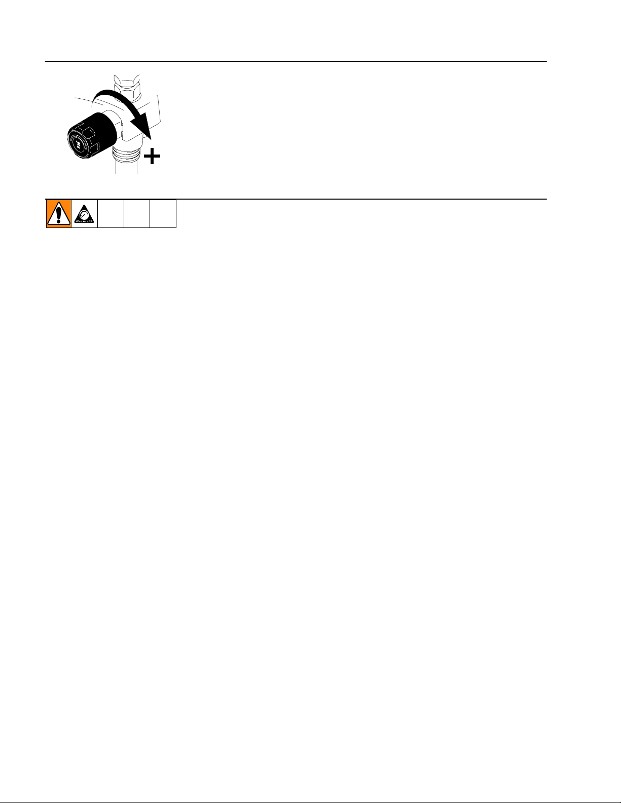
Pressure is set at minimum. Turn Pressure Control Knob to the right (clockwise) to
Motor or control is damaged. Return sprayer to Graco authorized service center.
Paint is frozen or hardened in
pump.
Trigger safety is in SAFETY
ON position.
Pump check valves are dirty
or damaged.
Spray/Prime valve is worn or
obstructed with debris.
Pump is not primed. See Priming on page 9.
Inlet screen is clogged or
suction tube is not immersed.
Paint pail is empty. Refill paint pail and reprime sprayer.
Suction tube has vacuum air
leak.
Pump check ball is stuck. See “Pump will not prime” section of Trouble Shooting
Turn Spray/Prime valve to PRIME (pointing down).
service center if drain valve is plugged.
Clean debris off inlet screen. Make sure suction tube is at
bottom of paint pail.
dislodge the ball, allowing the pump to prime properly. OR
Power Flush the unit (page 20).
Remove hose from sprayer. Unscrew outlet valve to remove
assembly. Gently nudge the ball in the outlet assembly with a
screwdriver. Screw the valve back into the pump.
Try a different outlet or reset building circuit breaker or replace
extension cord/power cord.
increase pressure.
Unplug sprayer from electrical outlet.
NOTE: If frozen, do not try to start sprayer until
completely thawed, or damage to motor, control board,
and/or drivetrain may occur.
Make sure power switch is OFF. Place sprayer in warm area
for several hours, then plug in and turn on. Slowly increase
pressure setting to see if motor starts.
If paint hardened in sprayer, pump packings, valves, drivetrain,
or pressure switch may need to be replaced.
Put trigger safety in SAFETY OFF position.
Clean or replace check valves.
Return sprayer to Graco authorized service center.
Clean debris off inlet screen. Make sure suction tube is at
bottom of pail. Reprime sprayer.
Tighten suction tube connection. Inspect for cracks or vacuum
leaks. If cracked or damaged, replace suction tube.
instructions.
28 309388
Page 29

Troubleshooting
g
intermittentl
NOTE: This is a thermal
excessive heat
2. Damage can occur if
as soon as sprayer is plugged
PROBLEM CAUSE SOLUTION
Pump cycles but paint only
dribbles or spurts when
trigger is pulled.
Pressure is set at maximum,
but cannot achieve a good
spray pattern.
When paint is sprayed, it runs
down the wall or sags.
When paint is sprayed, coat is
not covering.
Motor is hot and runs
y.
NOTE: This is a thermal
overload condition. Motor will
automatically shut off due to
.
See Startup Hazard After
Thermal Overload on page
2. Damage can occur if
cause is not corrected.
Pressure is set too low. Turn Pressure Control Knob to the right (clockwise) to
increase pressure.
Tip is clogged. Clear tip. See your gun manual.
Spray tip is too large or worn. Replace tip.
Gun filter is clogged. Clean or replace In–line Valve fluid filter. Page 25.
Extension cord is too long or
not a heavy enough gauge.
Tip is too large for sprayer. Select a smaller tip.
Tip is worn beyond capability
of sprayer.
Gun filter is clogged. Clean or replace In–line Valve fluid filter. Page 25.
Inlet screen is clogged. Clean debris off inlet screen.
Pump valves are worn. Check for worn pump valves as follows: Prime sprayer with
Coat is going on too thick. Move gun faster.
Coat is going on too thin. Move gun slower.
Vent holes in shroud are
plugged, or sprayer is
covered.
Extension cord is too long or
not a heavy enough gauge.
Unregulated electrical
generator being used has
excessive voltage.
Sprayer was operated at high
pressure with small tip, which
caused frequent motor starts
and excessive heat build up.
Replace extension cord.
Replace tip.
paint. See Priming on page 9. Trigger In–line Valve
momentarily. When trigger is released, pump should cycle
momentarily and stop. If pump continues to cycle, pump
valves may be worn. Replace check valves.
Choose tip with smaller hole size.
Choose tip with wider fan.
Make sure gun is far enough from surface.
Choose tip with larger hole size.
Choose tip with narrower fan.
Make sure gun is close enough to surface.
Keep vent holes in shroud clear of obstructions and overspray,
and keep sprayer open to air.
Replace extension cord.
Use electrical generator with a proper voltage regulator.
Sprayer requires a 120V AC, 60 Hz, 1500-Watt generator.
Decrease pressure setting, or increase tip size.
Building circuit breaker opens
after sprayer operates for 5 to
10 minutes.
OR
Building circuit breaker opens
into outlet, and sprayer is
turned on.
Too many appliances are
plugged in on same circuit.
Extension cord is damaged or
too long or not a heavy
enough gauge.
Sprayer power cord is
damaged.
Free up circuit (unplug things), or use a less busy circuit.
D Plug in something that you know is working to test
extension cord.
D Replace extension cord.
Check for broken insulation or wires. Replace power cord if
damaged.
29309388
Page 30

Fan pattern varies
dramatically while spraying or
sprayer does not turn on
promptly when resuming
spraying.
Spray comes out of gun in
two thick streams.
Pressure control switch is
worn and causing excessive
pressure variation.
Reversible tip is in UNCLOG
position.
Return sprayer to Graco authorized service center.
Rotate arrow–shaped handle on tip so it points forward in
SPRAY pattern.
Sprayer does not turn on
promptly when resuming
spraying.
Paint is coming out of
pressure control switch.
Pressure drain actuates
automatically, relieving
pressure through prime tube.
Paint leaks down outside of
pump.
Pressure control switch is
worn and causing excessive
pressure variation.
Pressure control switch is
worn.
System is overpressurizing. Return sprayer to Graco authorized service center.
Pump packings are worn. Replace pump packings.
Return sprayer to Graco authorized service center.
Return sprayer to Graco authorized service center.
30 309388
Page 31

Service – Changing the Needle on the Contractort In–line Valve
NOTE: The needle, diffuser/seat, gasket and locknut must be replaced together. They are included
in Repair Kit 218070.
Disassembly
1. Relieve pressure, page 6.
2. Squeeze trigger while unscrewing diffuser/seat and
gasket.
trigger guard
3. Remove Trigger. Remove locknut and bracket.
bracket
locknut
4. Tap rear of the In–line Valve with plastic mallet and
punch to push needle assembly out through front of
housing.
31309388
Page 32

Service – Changing the Needle on the Contractort In–line Valve
NOTE: The needle, diffuser/seat, gasket and locknut
must be replaced together. They are included in Repair
Kit 218070.
Reassembly
1. Guide threaded end of needle assembly into front of
In–line Valve.
2. Install bracket and locknut loosely on threaded end of
needle. Squeeze trigger to pull needle assembly into
In–line Valve body. Tighten locknut and install
trigger guard.
bracket
locknut
trigger guard
3. Squeeze trigger while installing gasket and diffuser/
seat. Torque diffuser/seat to 26–32 ft–lb (35–43 N·M).
26–32 lb
4. If In–line Valve handle was removed, hand tighten into
fluid housing. It should fit easily. Be sure trigger guard
is reassembled.
32 309388
5. Adjust needle before using In–line Valve.
Page 33

Service – Adjusting the Needle on the Contractort In–line Valve
1. Engage In–line Valve safety latch.
2. Hold In–line Valve with nozzle straight up.
5/16”
3. Remove trigger guard.
4. Hold your finger against trigger with light pressure.
Using a 5/16–in, open ended wrench, turn locknut
clockwise until you feel trigger depress slightly.
33309388
Page 34

Service – Adjusting the Needle on the Contractort In–line Valve
5. Turn adjusting nut 3/4 turn counterclockwise.
5/16”
3/4 turn
6. Connect fluid hose. Use a wrench to tighten.
7. Prime system. Page 9.
Trigger
8. Trigger the In–line Valve and release it. The fluid
should stop immediately.
Release
9. Engage safety latch and try to trigger In–line Valve.
NO FLUID SHOULD FLOW.
If the In–line Valve fails either test, relieve pressure, disconnect hoses and readjust needle.
No Fluid
34 309388
Page 35

Notes
35309388
Page 36

150 RPX Model 233687
Parts
Ref.
No. Part No. Description Qty.
1 15A680 FRAME 1
2 195697 STRAINER 1
3 244035 DEFLECTOR, barbed 1
5 15A473 TUBE, suction 1
6 15H772 SUPPORT, frame 1
7 196586 COVER, switch 1
8 113955 SCREW 4
9 102040 NUT, lock 4
12 15A475 TUBE, drain 1
13 115489 CLAMP, drain tube 2
23 244266 KIT, pressure switch, repair 1
30 224807 CAM, drain valve 1
31 235014 KIT, valve, repair 1
32 111600 DRIVE PIN, drain valve 1
38 187625 HANDLE, drain valve 1
41 245148 KIT, motor enclosure (includes
enclosure and 2 warning labels) 1
42 245147 KIT, cover, housing (includes 3 labels,
2 dowel pins, 2 bushings) 1
Ref.
No. Part No. Description Qty.
44 245149 KIT, gear, (includes two gears
and connecting rod) 1
50 245078 KIT, pump repair 1
51 245079 KIT, control board 1
52 245080 KIT, motor, repair 1
53 245076 KIT, outlet valve 1
54 245077 KIT, inlet valve 1
55 116295 CLAMP, spring, .88 diameter 1
56 115478 SCREW, machine; pan head 2
57 196594 CORD, power 1
58 243954 HOSE, DuraFlex, 3/16 in. x 25 ft 1
(available from Service Center only)
61Y 196932 LABEL, warning 1
62Y 198668 LABEL, warning 1
63 115477 SCREW, machine, pan head 9
64 196574 FITTING, drain 1
66 103473 STRAP, tie 1
69+ 115648 VALVE, shutoff, power flush 1
Y Replacement Danger and Warning labels, tags and cards are
available at no cost.
+ Not shown.
36 309388
Page 37

150 RPX Model 233687
150 RPX Model 233687
1
1
Apply light coat of lithium–based grease.
Apply light coat of lithium–based grease.
50
50
1
1
57
57
51
51
63
63
42
42
44
44
53
63
63
53
30, 32, 38
30, 32, 38
31
31
64
64
13
13
54
23
23
12
52
52
7
7
62
62
55
55
5
5
12
13
13
58
58
41
41
61
61
1
1
56
56
3
3
2
2
9
9
8
8
ti8469a
6
6
37309388
Page 38

Pressure Roller Assembly Model 244279
Parts List
78
79
c
b
a
d
g
f
h
e
Ref.
No. Part No. Description Qty.
78 244271 FRAME, roller includes a, b, c, d, e, f 1
a FRAME
b 246277 CAP, end (includes seal, retainer, and
o–ring) 1
c 15B065 DIFFUSER 2
d 197106 CLIP, roller 1
e 107590 ROLLER, cover, 9 inch,
1/2 in. (13 mm) nap 1
f 115524 GASKET 1
g 245999 CAP, end (includes seal and retainer) 1
79 232122 EXTENSION, includes h, k, m
h EXTENSION, 20 in. (50 cm) 1
k 162863 GASKET 1
m 114049 O–RING 1
m
Additional Roller Covers
HINT:
k
When replacing gasket k*) and
o-ring (m*), position o-ring first,
then press gasket into place.
The following pressure roller covers are available at
your local distributor:
107590 9 in. (23 cm); 1/2 in. (13 mm) nap
107591 9 in. (23 cm); 3/4 in. (19 mm) nap
107592 9 in. (23 cm); 1-1/4 in. (32 mm) nap
38 309388
Page 39

Notes
39309388
Page 40

Contractort In–line Valve
Model 244161
Parts List
Ref.
No. Part No. Description Qty.
101 218070 NEEDLE–DIFFUSER/SEAT KIT 1
102 244193 TRIGGER, valve, In–line 1
103 196869 GUARD, trigger 1
104 238817 KIT, swivel 1
105n 218131 FLUID FILTER ASSEMBLY 1
(standard 50 mesh) includes
replacement parts 5a, 5b, 5c, 5d
105a 179722 RETAINER, spring 1
105b 179731 ELEMENT, strainer 1
105c 179763 SPRING, compression 1
105d 179750 RETAINER, spring 1
106n 179733 SEAL, sleeve 1
107 107110 LOCKNUT 1
108 197052 ADAPTER, RAC 1
110 197058 BRACKET, stem 1
Ref.
No. Part No. Description Qty.
111 197568 HOUSING, fluid, locking 1
112 113409 RETAINER, guard 1
113 195788 HANDLE, valve 1
114 104938 PACKING, o–ring 1
119 177538 STUD, trigger 2
120 105334 NUT, lock, hex 2
121Y 222385 WARNING CARD (not shown) 1
123Y 187348 COVER, warning 1
Y Replacement Danger and Warning labels, tags and cards are
available at no cost.
n Keep these spare parts on hand to reduce down time.
D Part number provided for reference only. Not available as a replace-
ment part.
40 309388
Page 41

Contractort In–line Valve Model 244161
101
119
Parts
108
111
103
110
102
113
112
105a
120
106
105b
107
105
105c
105d
114
TI0667
104
41309388
Page 42

Technical Data
Maximum fluid working pressure – sprayer 2800 psi (19 MPa, 193 bar). . . . . . . . . . . . . . . . . . . . . . . . . . . . . . . . . . . . . . .
Maximum fluid working pressure – Contractort In–line Valve, extension, roller* 3600 psi (25 MPa, 248 bar). . . . . . .
Sprayer inlet size 3/4 in. internal thread (standard garden hose). . . . . . . . . . . . . . . . . . . . . . . . . . . . . . . . . . . . . . . . . . . . .
Sprayer outlet size 1/4 npsm external thread. . . . . . . . . . . . . . . . . . . . . . . . . . . . . . . . . . . . . . . . . . . . . . . . . . . . . . . . . . . . .
Contractort In–line Valve fluid inlet size 1/4 npsm (swivel). . . . . . . . . . . . . . . . . . . . . . . . . . . . . . . . . . . . . . . . . . . . . . . . . .
Contractort In–line Valve fluid outlet size 7/8–14 unf. . . . . . . . . . . . . . . . . . . . . . . . . . . . . . . . . . . . . . . . . . . . . . . . . . . . . .
Electric motor 3/8 hp 7A open frame universal. . . . . . . . . . . . . . . . . . . . . . . . . . . . . . . . . . . . . . . . . . . . . . . . . . . . . . . . . . . . .
Sprayer weight only 13 lb (6 kg). . . . . . . . . . . . . . . . . . . . . . . . . . . . . . . . . . . . . . . . . . . . . . . . . . . . . . . . . . . . . . . . . . . . . . . . .
Dimensions . . . . . . . . . . . . . . . . . . . . . . . . . . . . . . . . . . . . . . . . . . . . . . . . . . . . . . . . . . . . . . . . . . . . . . . . . . . . . . . . . . . . . . . . . . .
Length 14.9 in. (37.8 cm). . . . . . . . . . . . . . . . . . . . . . . . . . . . . . . . . . . . . . . . . . . . . . . . . . . . . . . . . . . . . . . . . . . . . . . . . . . .
Width 15.0 in. (38.1 cm). . . . . . . . . . . . . . . . . . . . . . . . . . . . . . . . . . . . . . . . . . . . . . . . . . . . . . . . . . . . . . . . . . . . . . . . . . . . .
Height 15.6 in. (39.6 cm). . . . . . . . . . . . . . . . . . . . . . . . . . . . . . . . . . . . . . . . . . . . . . . . . . . . . . . . . . . . . . . . . . . . . . . . . . . .
Wetted parts sprayer . . . . . . . . . . . . . . . . . . . . . . . . . . . . . . . . . . . . . . . . . . . . . . . . . . . . . . . . . . . . . . . . . . . . . . . . . . . . . . . . . . .
stainless steel, brass, ultra–high molecular weight polyethylene (UHMWPE), leather
carbide, nylon, aluminum, PVC, polypropylene, fluroelastomer
Wetted parts Contractort In–line Valve UHMWPE, aluminum, tungsten carbide, stainless steel, PTFE, brass. . . . .
Inlet Screen on Suction Tube 35 mesh (450 microns). . . . . . . . . . . . . . . . . . . . . . . . . . . . . . . . . . . . . . . . . . . . . . . . . . . . . .
Maximum material temperature 120_F (50_ C). . . . . . . . . . . . . . . . . . . . . . . . . . . . . . . . . . . . . . . . . . . . . . . . . . . . . . . . . . . .
Contractort In–line Valve fluid Valve orifice size 0.125 in. (2.286 mm) dia.. . . . . . . . . . . . . . . . . . . . . . . . . . . . . . . . . . . .
Electrical power requirement 120V AC, 60 Hz, 1 phase, 15A. . . . . . . . . . . . . . . . . . . . . . . . . . . . . . . . . . . . . . . . . . . . . . . .
Sound data * Contractort In–line Valve
Sound pressure level 78 dB(A). . . . . . . . . . . . . . . . . . . . . . . . . . . . . . . . . . . . . . . . . . . . . . . . . . . . . . . . . . . . . . . . . . . . . . .
Sound power level 87 dB(A). . . . . . . . . . . . . . . . . . . . . . . . . . . . . . . . . . . . . . . . . . . . . . . . . . . . . . . . . . . . . . . . . . . . . . . . . .
* Measured while spraying waterbase paint – specific gravity 1.36 through a 517 tip at 3,000 psi (21 MPa, 207 bar)
per ISO 3744. Actual sound levels may vary with length of extension used.
* The best operating pressure is the lowest pressure that provides an even paint supply to the roller and typically does
not exceed 300 psi (2.1 MPa, 21 bar).
42 309388
Page 43

Notes
43309388
Page 44

Graco Standard Warranty
Graco warrants all equipment manufactured by Graco and bearing its name to be free from defects in material and workmanship on the
date of sale to the original purchaser for use. With the exception of any special, extended, or limited warranty published by Graco,
Graco will, for a period of twelve months from the date of sale, repair or replace any part of the equipment determined by Graco to be
defective. This warranty applies only when the equipment is installed, operated and maintained in accordance with Graco’s written
recommendations.
This warranty does not cover, and Graco shall not be liable for general wear and tear, or any malfunction, damage or wear caused by
faulty installation, misapplication, abrasion, corrosion, inadequate or improper maintenance, negligence, accident, tampering, or substitution of non–Graco component parts. Nor shall Graco be liable for malfunction, damage or wear caused by the incompatibility of
Graco equipment with structures, accessories, equipment or materials not supplied by Graco, or the improper design, manufacture,
installation, operation or maintenance of structures, accessories, equipment or materials not supplied by Graco.
This warranty is conditioned upon the prepaid return of the equipment claimed to be defective to an authorized Graco distributor for
verification of the claimed defect. If the claimed defect is verified, Graco will repair or replace free of charge any defective parts. The
equipment will be returned to the original purchaser transportation prepaid. If inspection of the equipment does not disclose any defect
in material or workmanship, repairs will be made at a reasonable charge, which charges may include the costs of parts, labor, and
transportation.
THIS WARRANTY IS EXCLUSIVE, AND IS IN LIEU OF ANY OTHER WARRANTIES, EXPRESS OR IMPLIED, INCLUDING BUT
NOT LIMITED TO WARRANTY OF MERCHANTABILITY OR WARRANTY OF FITNESS FOR A PARTICULAR PURPOSE.
Graco’s sole obligation and buyer’s sole remedy for any breach of warranty shall be as set forth above. The buyer agrees that no other
remedy (including, but not limited to, incidental or consequential damages for lost profits, lost sales, injury to person or property, or any
other incidental or consequential loss) shall be available. Any action for breach of warranty must be brought within two (2) years of the
date of sale.
Graco makes no warranty, and disclaims all implied warranties of merchantability and fitness for a particular purpose in connection
with accessories, equipment, materials or components sold but not manufactured by Graco. These items sold, but not manufactured
by Graco (such as electric motors, switches, hose, etc.), are subject to the warranty, if any, of their manufacturer. Graco will provide
purchaser with reasonable assistance in making any claim for breach of these warranties.
In no event will Graco be liable for indirect, incidental, special or consequential damages resulting from Graco supplying equipment
hereunder, or the furnishing, performance, or use of any products or other goods sold hereto, whether due to a breach of contract,
breach of warranty, the negligence of Graco, or otherwise.
FOR GRACO CANADA CUSTOMERS
The parties acknowledge that they have required that the present document, as well as all documents, notices and legal proceedings
entered into, given or instituted pursuant hereto or relating directly or indirectly hereto, be drawn up in English. Les parties reconnaissent avoir convenu que la rédaction du présente document sera en Anglais, ainsi que tous documents, avis et procédures judiciaires
exécutés, donnés ou intentés à la suite de ou en rapport, directement ou indirectement, avec les procedures concernées.
TO PLACE AN ORDER, contact your Graco distributor, or call this number to identify the distributor closest to you:
1–800–690–2894 Toll Free
All written and visual data contained in this document reflects the latest product information available at the time of publication.
Graco reserves the right to make changes at any time without notice.
44 309388
MM 309388
Graco Headquarters: Minneapolis
International Offices: Belgium, China, Japan, Korea
www.graco.com
Written in USA 7/2001, Rev 9/2006
 Loading...