

Page 1
Instructions--Parts List
R
President
For use with Graco fluid handling pumps.
See your pump instruction manual for Maximum Working Pressure.
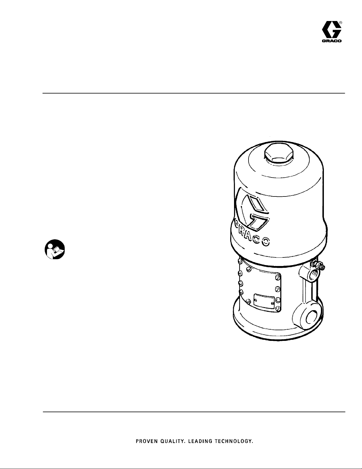
Model 205647, Series M
For in-line mounting, medium-pressure oil pump
Model 206078, Series M
For in-line mounting, high-pressure grease pump
Model 205038, Series N
For stanchion tube mounting
Model 207352, Series G
For divorced mounting
Model 222772, Series G
For divorced mounting
Important Safety Instructions
Read all warnings and instructions in this manual.
Save these instructions.
Air Motors
306982ZAC
EN
Table of Contents
Warnings 2......................................
Installation 5.....................................
Operation 7.....................................
Service 8.......................................
Parts Drawings and Parts LIsts
Model 205647 14..............................
Model 206078 16..............................
Model 205038 18..............................
Model 207352 20..............................
Model 222772 22..............................
Mounting Hole Layouts 24.........................
Dimensional Drawing 24..........................
Technical Data 25................................
Graco Standard Warranty 26......................
Graco Phone Number 26..........................
Model 207352 Shown
Page 2
Symbols
Warning Symbol
WARNING
This symbol alerts you to the possibility of serious
injury or death if you do not follow the instructions.
WARNING
EQUIPMENT MISUSE HAZARD
Equipment misuse can cause the equipment to rupture or malfunction and result in serious injury.
D This equipment is for professional use only.
D Read all instruction manuals, tags, and labels before operating the equipment.
D Use the equipment only for its intended purpose. If you are not sure, call your Graco distributor.
D Do not alter or modify this equipment.
D Check equipment daily. Repair or replace worn or damaged parts immediately.
Caution Symbol
CAUTION
This symbol alerts you to the possibility of damage to
or destruction of equipment if you do not follow the
instructions.
D Do not exceed the maximum working pressure stated on the equipment or in the Technical Data
for your equipment. Do not exceed the maximum working pressure of the lowest rated component
in your system.
D Use fluids and solvents which are compatible with the equipment wetted parts. Refer to the Tech-
nical Data section of all equipment manuals. Read the fluid and solvent manufacturer’s warnings.
D Handle hoses carefully. Do not pull on hoses to move equipment.
D Route hoses away from traffic areas, sharp edges, moving parts, and hot surfaces. Do not expose
Graco hoses to temperatures above 66_C (150_F) or below --40_C(--40_F).
D Wear hearing protection when operating this equipment.
D Do not move or lift pressurized equipment.
D Comply with all applicable local, state, and national fire, electrical, and safety regulations.
D Never exceed 180 psi (1.2 MPa, 12 bar) air pressure to the motor, and never exceed the stated
maximum working pressure of the pump or the lowest rated component in your system. Refer to
your separate pump instruction manual.
D Be sure that all spray/dispensing equipment and accessories are rated to withstand the maximum
air and fluid working pressures of this system. Do not exceed the maximum working pressure of
any component or accessory used in the system.
2 306982
Page 3
WARNING
SKIN INJECTION HAZARD
Spray from the gun, leaks or ruptured components can inject fluid into your body and cause extremely
serious injury, including the need for amputation. Fluid splashed in the eyes or on the skin can also
cause serious injury.
D Fluid injected into the skin is a serious injury. The injury may look like just a cut, but it is a serious
injury. Get immediate surgical treatment.
D Do not point the dispensing valve at anyone or any part of the body.
D Do not put your hand or fingers over the end of the dispensing valve.
D Do not stop or deflect leaks with your hand, body, glove or rag.
D Use only extensions and no-drip tips that are designed for use with your dispensing valve.
D Tighten all fluid connections before operating the equipment.
D Check the hoses, tubes, and couplings daily. Replace worn or damaged parts immediately . Do not
repair high pressure couplings; you must replace the entire hose.
MOVING PARTS HAZARD
Moving parts can pinch or amputate your fingers.
D Keep clear of all moving parts when starting or operating the pump.
D Before checking or servicing the equipment, follow the Pressure Relief Procedure on page 6 to
prevent the equipment from starting unexpectedly.
3306982
Page 4
WARNING
FIRE AND EXPLOSION HAZARD
Improper grounding, poor ventilation, open flames or sparks can cause a hazardous condition and result in a fire or explosion and serious injury.
D Ground the equipment and the object being sprayed. Refer to Grounding on page 5.
D If there is any static sparking or you feel an electric shock while using this equipment, stop spray-
ing immediately. Do not use the equipment until you identify and correct the problem.
D Provide fresh air ventilation to avoid the buildup of flammable fumes from solvents or the fluid
being sprayed.
D Keep the spray area free of debris, including solvent, rags, and gasoline.
D Before operating this equipment, electrically disconnect all equipment in the spray area.
D Before operating this equipment, extinguish all open flames or pilot lights in the spray area.
D Do not smoke in the spray area.
D Do not turn on or off any light switch in the spray area while spraying or while operating if fumes
are present.
D Do not operate a gasoline engine in the spray area.
TOXIC FLUID HAZARD
Hazardous fluid or toxic fumes can cause serious injury or death if splashed in the eyes or on the skin,
inhaled, or swallowed.
D Be sure that all fluids and solvents used are chemically compatible with the wetted parts shown in
the Technical Data section of your pump manual. Always read the manufacturer’s literature before
using fluid or solvent in your pump.
D Know the specific hazards of the fluid you are using.
D Store hazardous fluid in an approved container . Dispose of hazardous fluid according to all local,
state and national guidelines.
D Always wear protective eyewear, gloves, clothing and respirator as recommended by the fluid and
solvent manufacturer.
United States Government safety standards have been adopted under the Occupational Safety and Health Act. You
should consult these standards -- particularly the General Standards, Part 1910, and the Construction Standards,
Part 1926.
4 306982
Page 5
General Information
Installation
NOTE: Reference numbers and letters in parentheses
in the text refer to the callouts in the figures and the
parts drawing.
NOTE: Always use Genuine Graco Parts and
Accessories, available from your Graco distributor.
Grounding
WARNING
FIRE AND EXPLOSION HAZARD
Before operating the pump, ground the
system as explained below. Also read
the section FIRE OR EXPLOSION HAZ-
ARD on page 4.
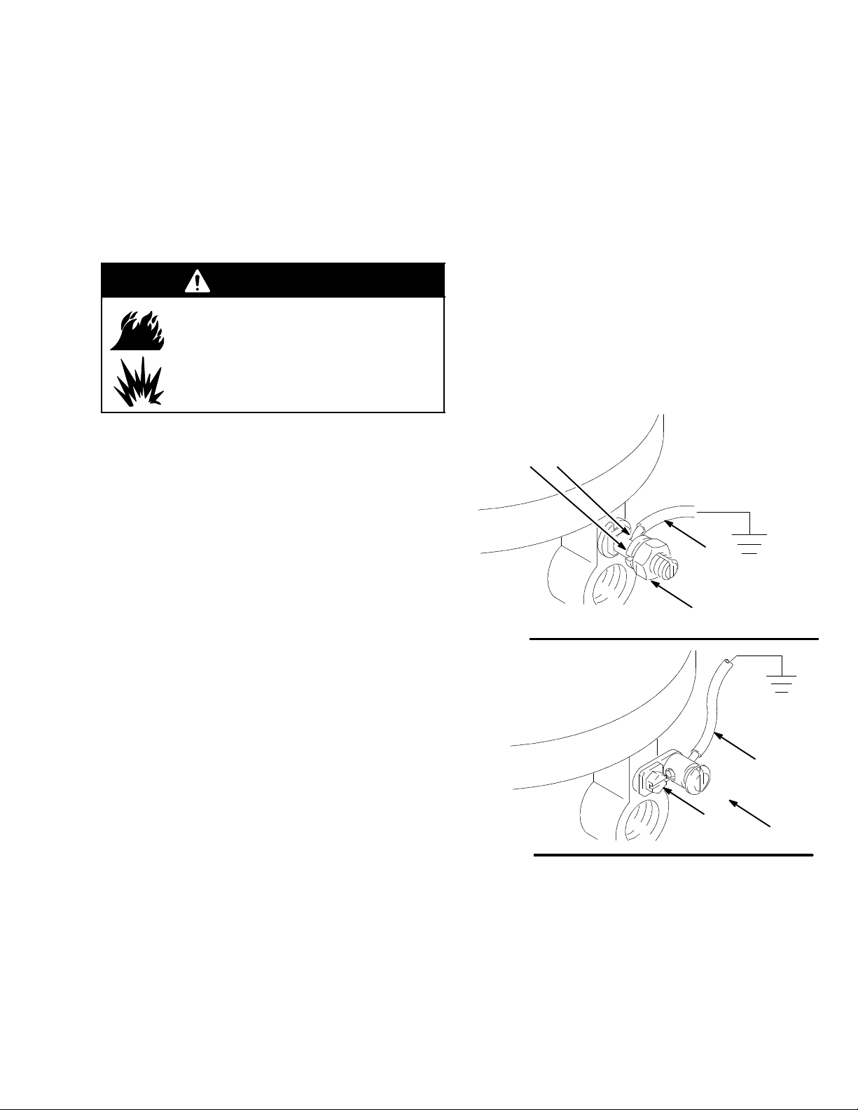
D Pump: Use a ground wire and clamp as shown in
Fig. 1. Loosen the grounding lug locknut (A) and
washer (B). Insert one end of a 12 ga (1.5 mm@)
minimum ground wire (C) into the slot in lug (D) and
tighten the locknut securely. Connect the other end
of the wire to a true earth ground.
D Spray gun and dispensing valve: Ground through
connection to a properly grounded fluid hose and
pump.
D Object being sprayed: Follow your local code.
D Solvent pails used when flushing: Follow your local
code. Use only metal pails, which are conductive,
placed on a grounded surface. Do not place the pail
on a nonconductive surface, such as paper or
cardboard, which interrupts the grounding
continuity.
D To maintain grounding continuity when flushing or
relieving pressure, hold a metal part of the spray
gun firmly to the side of a grounded metal pail, then
trigger the gun.
DB
Model No. 206078: Remove the ground screw (Z)
and insert through the eye of the ring terminal at
end of ground wire (Y). Fasten the ground screw
back onto the pump and tighten securely. Connect
the other end of the ground wire to a true earth
ground. See Fig. 2. To order a ground wire and
clamp, order Part No. 22201 1.
D Air, and fluid hoses: Use only electrically
conductive hoses.
D Air compressor: Follow manufacturer’s
recommendations.
Fig. 1
Fig. 2
C
A
0720
Y
Z
TI1052
5306982
Page 6
Installation
Pressure Relief Procedure
WARNING
SKIN INJECTION HAZARD
Fluid under high pressure can be injected through the skin and cause
serious injury. To reduce the risk of an
injury from injection, splashing fluid, or moving
parts, follow the Pressure Relief Procedure
whenever you
D Areinstructedtorelievethepressure
D Stop spraying
D Check or service any of the system equipment
D Install or clean the spray tips
1. Engage the spray gun/dispensing valve safety
latch.
2. Shut off the air to the motor.
3. Close the bleed-type master air valve (required in
your system).
4. Disengage the gun/valve safety latch.
WARNING
A bleed-type master air valve is required in your
system to reduce the risk of serious bodily injury
from moving parts if you are adjusting or repairing
the air motor.
The bleed-type master air valve relieves air trapped
between this valve and the motor after the air
regulator is shut off. T rapped air can cause the
motor and pump to cycle unexpectedly. Install the
valve between the pump air inlet and the air
regulator within easy reach of the pump.
WARNING
Moving parts can pinch or amputate your fingers or
other body parts. When the pump is operating, the
priming piston (located at the pump intake) and the
air motor piston (located behind the air motor
plates) move. Never Operate the pump with the air
motor plates removed, and keep your fingers and
hands away from the priming piston. See Moving
Parts Hazard on page 3.
5. Hold a metal part of the gun/valve firmly to the side
of a grounded metal pail, and trigger the gun/valve
to relieve pressure.
6. Engage the gun/valve safety latch.
7. Open the pump drain valve (required in your
system), having a container ready to catch the
drainage.
8. Leave the drain valve open until you are ready to
spray/dispense again.
If you suspect that the spray tip/nozzle or hose is
completely clogged, or that pressure has not been fully
relieved after following the steps above, very slowly
loosen the tip guard retaining nut or hose end coupling
and relieve pressure gradually, then loosen completely,
then clear the tip/nozzle or hose.
6 306982
Page 7

Operation
NOTE: See your separate pump manual for detailed
operation instructions.
Restarting a Stalled Air Motor
CAUTION
Never exceed 180 psi (1.2 MPa, 12 bar) air supply
pressure to the air motor . Exceeding this pressure
may cause the air motor to stall with the air transfer
valves stuck at mid position, making the air motor
inoperative.
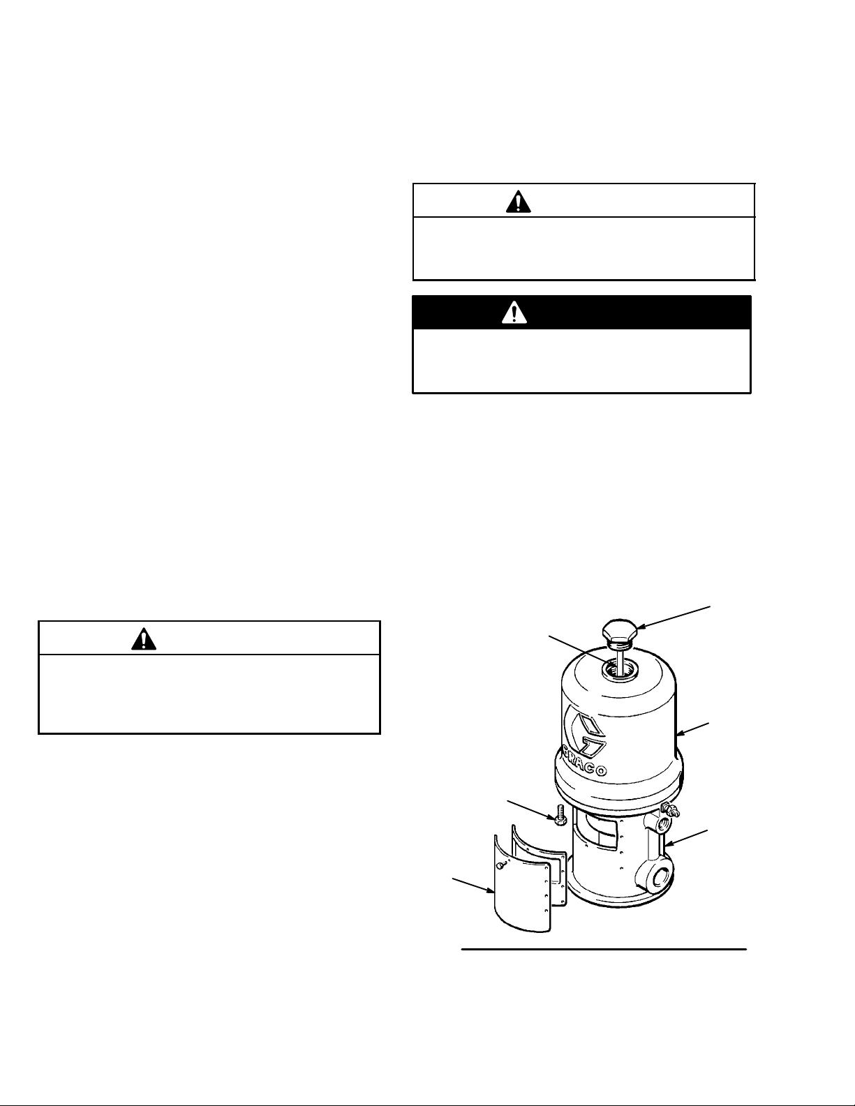
To reseat the air transfer valves and restart a stalled
air motor , relieve the air supply pressure to the motor
by closing the bleed-type master air valve. If the air
transfer valves fail to reseat, screw the cap nut (F) out
of the cylinder (G), pull up on the trip rod (H) and
screw the cap nut back into the cylinder . See Fig. 2.
Be sure the air supply pressure is less than 180 psi
(1.2 MPa, 12 bar) before opening the bleed-type
master air valve.
7306982
Page 8
Servicing the Air Motor
Service
Before you Start
D Be sure you have all necessary parts on hand. Air
Motor Repair Kit 207385 includes repair parts for
the motor. Use all the parts in the kit for best
results. Parts included in the air motor kit are
marked with double asterisks (**) in text and
drawings. See the parts list and drawing for your
pump (pages 14 to 22) for further information.
D Two accessory tools should be used. Padded
pliers, 207579 is used to grip the trip rod without
damaging its surface. Gauge, 171818, is used to
ensure the proper clearance between the poppets
and seat of the transfer valve.
Disassembly
1. Flush the pump. Follow the Pressure Relief
Procedure Warning, at left, before proceeding.
2. Disconnect the air hose from the motor. If
necessary, disconnect the motor from the pump.
Clamptheairmotorbaseinavise.
3. Manually push up on the piston rod to move the
piston assembly to the top of its stroke. Unscrew
the cylinder cap nut (F) from the cylinder (G). Pull
up on the cap nut. Grip the trip rod (H) with
padded pliers 207579 and screw the cap nut off
thetriprod.SeeFig.2.
4. Remove the eight screws (Z) holding the cylinder
(G) to the base (J). Carefully pull the cylinder
straight up off the piston. See Fig. 2.
CAUTION
To avoid damaging the cylinder wall, ALWAYS lift the
cylinder straight up off of the piston. Never tilt the
cylinder as it is being removed.
WARNING
Always keep fingers clear of the toggle assemblies
(E), to avoid pinching or amputating them. See
Fig. 3.
5. Use a screwdriver to push down on the trip rod
yoke (K) and snap the toggle assemblies (E)
down. See Fig. 3. Remove the lockwires (L) from
the adjusting nuts (M and Q) of the transfer valves
(N). Screw the top nuts (M) off. Screw the valve
stems (O) out of the grommets (P) and lower
adjusting nuts (Q). Take the valve poppets (R) off
the stems and squeeze them firmly to check for
cracks.
F
CAUTION
Do not damage the plated surface of the trip rod.
Damaging the surface of the trip rod can result in
erratic air motor operation. Use the special padded
pliers, 207579, to grasp the rod.
H
Hold trip rod with
padded pliers
207579, to prevent
damage to rod
G
Z
J
BB
Fig. 2
8 306982
Page 9

Service
6. Grip the toggle rockers (S) with a pliers. Compress
the springs (T) and swing the toggle assembly (E)
up and away from the piston lugs (U), and remove
the parts. Check that the valve actuator (V) is
supported by the spring clips (W), but slides easily
into them. See Fig. 3.
7. Remove the trip rod yoke (K), valve actuator (V)
and trip rod (H). Check the exhaust valve poppets
(X) for cracks.
Push toggles (E) in
and then up.
Turn wires up.
T
E
S
U
HK
L**
M**
O**
P**
Q**
NOTE: To remove the exhaust valve poppets (X),
stretch them out and cut with a sharp knife.
8. Pull the piston (Y) up out of the base (J) and
inspect the piston o-ring (AA) and the o-ring in the
base casting.
Cut off tops of
poppets (x) as
indicated by dotted
lines
H
W
V
X**
O**
M**
Fig. 3
W
P**
Q**
0.125 in.
(3.18 mm)
R**
Y
AA**
N
Y
J
CUTAWAY VIEW
V
X**
R**
9306982
Page 10

Service
Reassembly
1. Clean all the parts carefully in a compatible solvent
and inspect for wear or damage. Use all the repair
kit parts during reassembly and replace other parts
as necessary.
2. Check the polished surfaces of the piston, piston
rod and cylinder wall for scratches or wear. A
scored rod will cause premature packing wear and
leaking.
3. Lubricate all parts with a light, waterproof grease.
4. Be sure the o-rings are in place. Slide the piston
rod down through the throat bearing and lower the
piston (Y) into the air motor base (J).
7. Set gap on inlet valve (N) using the .125 in. (3.18
mm) side of gauge 171818. Rotate valve stem
(O**) until snug against gauge, then back of f until
valve stem slot is lined up with wire holes in valve
nut (M**) (do not back off more than 1/2 turn). See
Fig. 3. Install lockwires (L**) in the adjusting nuts
M** and Q**).
8. Snap the toggle assemblies (E) to the up position.
Reinstall the cylinder (G) and hold the trip rod (H)
in place with tool 207579. Apply a medium
strength thread locking compound to the threads of
the trip rod (H) and assemble the cap nut (F) to the
trip rod (H). Torque the cap nut (F) to 60 lb--in (6.8)
N--m). Install cap nut (F) into cylinder (G).
5. Pull the exhaust valve poppets (X**) into the valve
actuator (V) and clip off the top part shown with
dotted lines. See Fig. 3.
6. Install the transfer valve poppets (R**) onto the
valve stems (O**), then reassemble the valve
stems (O**), bottom adjusting nuts (Q**),
grommets (P**), and top adjusting nuts (M**) on
thepiston(Y).Assemblethetriprod(H),valve
actuator (V), trip rod yoke (K) and toggle
assemblies (E) on the piston. See Fig. 3.
9. Before remounting the pump, connect an air hose
and run the pump slowly, at about 40 psi
(0.28 MPa, 2.8 bar) to ensure that it operates
smoothly.
10. Reconnect the ground wire before regular
operation of the pump.
10 306982
Page 11

Service
Throat Packing Service for In-Line Pump M o del 205647
3. Remove one louvered air exhaust plate (BB) and
WARNING
The piston in the air motor, located behind the air
motor plates, moves when air is supplied to the
motor. Moving parts can pinch or amputate your
fingers or other body parts. Therefore, never
operate the pump with the air motor plates
removed.
NOTE: See Fig. 4 on page 12 and the Parts Drawing
on page 14.
1. Clamp the pump in a vise and unscrew the
displacement cylinder (CC) from the air motor
base (J). Pull the displacement cylinder away from
the air motor until the cotter pin (DD) which
secures the displacement pump connecting rod to
the air motor piston rod (FF) is visible. See Fig. 4.
unscrew the throat packing nut (HH), using a
spanner wrench or a 0.22 in. (5.6 mm) diameter
rod. See Fig. 4. Remove the spacer and packing
from the base and packing nut. Clean the throat
packing area in the base and the packing nut.
Clean and inspect all parts and replace as
necessary.
4. Lubricate the packings, piston rod and piston
flange with a light waterproof grease. Reinstall the
spacer and packing in the base and packing nut.
Be sure the lips of the v-packings face down. See
Detail B. Screw the packing nut loosely into the
base. Carefully slide the piston rod down through
the throat packing and lower the piston into the
base. T ighten the packing nut securely. Reinstall
the plate (BB) and cylinder (G). Reassemble the
air motor to the displacement pump.
2. Remove the cotter pin (DD) and unscrew the pump
connecting rod (EE) from the air motor piston rod
(FF). See Fig. 4. Remove the cylinder (G) from the
air motor base (J) as described under
Disassembly on page 8.
CAUTION
When reinstalling cotter pin (DD), always spread and
flatten the pin (both the head and prongs) around the
rodtowithina1in.(25mm)totaldiameter.See
Detail A of Fig. 4.
11306982
Page 12

In-Line Pump Models
205647 and 206078
Service
G
DETAIL B, for In-Line Pump Model 205647
DETAIL A
190249
J
HH
BB
CC
Fig. 4
1in.
(25 mm)
SEE DETAIL A
FF
DD
EE
B
112843
190495
NOTE: To avoid seal damage during installa-
tion, insert the seal at an angle as shown above,
so that side A is below hole C. Then press side
B down until the seal bottoms out.
C
A
12 306982
Page 13

Service
Throat Packing Service for In-Line Pump M o del 206078
5. Clean the throat packing area in the base and the
WARNING
The piston in the air motor, located behind the air
motor plates, moves when air is supplied to the
motor. Moving parts can pinch or amputate your
fingers or other body parts. Therefore, never
operate the pump with the air motor plates
removed.
See Fig. 4 on page 12 and the Parts Drawing on
page 16.
1. Clamp the pump in a vise and unscrew the
displacement cylinder (CC) from the air motor
base (J). Pull the displacement cylinder away from
the air motor until the cotter pin (DD) which
secures the displacement pump connecting rod to
the air motor piston rod (FF) is visible. See Fig. 4.
packing nut. Clean and inspect all parts, and
replace as necessary.
6. Lubricate the packings, piston rod and piston
flange with a light waterproof grease.
7. Install the washer (26{) into the base. Assemble
the packing (25{) and the wiper (22{) into the
retainer (24{). Install the o-ring (23{) onto the
retainer, and insert the retainer assembly into the
base.
NOTE: Make sure the packing (25{) lips face
down, and make sure the wiper (22{) lips face up.
8. Insert the bearing (46{) and the washer (44{)into
the base. Assemble the female gland (48{),
v-packings (49{), and the male gland (47{)into
the packing nut (45{).
2. Remove the cotter pin (DD) and unscrew the pump
connecting rod (EE) from the air motor piston rod
(FF). See Fig. 4. Remove the cylinder (G) from the
air motor base (J) as described under
Disassembly on page 8.
3. Remove one louvered air exhaust plate (BB) and
unscrew the throat packing nut (HH), using a
spanner wrench or a 0.22 in. (5.6 mm) diameter
rod. See Fig. 4.
4. Remove the packing nut (45{), male and female
glands (47{,48{), v-packings (49{), washer
(44{), bearing (46{), retainer (24{), wiper (22{),
o-ring (23{), u-cup (25{), and washer (26{)from
the base.
9. Reinstall the spacer and packing in the base and
packing nut (45{). Screw the packing nut into the
base, and tighten it securely. Carefully slide the
piston rod (FF) down through the throat packing,
and lower the piston into the base. Reinstall the
plate (BB) and cylinder (G). Reassemble the air
motor to the displacement pump.
10. Torque the outlet adapter (42) to 45 to 55 ft-lb (61
to 75 N-m).
CAUTION
When reinstalling cotter pin (DD), always spread and
flatten the pin (both the head and prongs) around the
rodtowithina1in.(25mm)totaldiameter.See
Detail A of Fig. 4.
13306982
Page 14

Model 205647, Series M
for in-line mounting, medium-pressure oil pump
31
*9
32
13 14
Parts
2
17
16
**20
15
29
*4
28**
27**
38**
18**
3
5
8
27**
1
34
37**
30**
7
25
10*
24
58
21**
19
33
14 306982
35
36
5354
6
33
57
Page 15

Model 205647, Series M
for in-line mounting, medium-pressure oil pump
Parts
Ref
No. Part No. Description Qty
1 207150 TRIP ROD 1
2 207391 PISTON
includes items 3 to 5 (also includes
207385 repair kit when ordered
as a replacement part) 1
3 102975 .SCREW, rd hd mach; 6--32 x 1/4 in. 2
4 158361* .CLIP, spring 2
5 .BARE PISTON (not sold separately) 1
6 17M262 SCREW, hex head; 8 --32 x 3/8 in. 20
7 101578 SCREW, hex head Nylock;
8--32x3/8in. 8
8 150647 GASKET; copper 1
9 156698* O-RING; Buna--N 1
10 112843* PACKING, block, V 1
13 158359 ACTUATOR, valve 1
14 158360 YOKE, rod, trip 1
15 158362 PIN, toggle 2
16 158364 ROCKER, toggle 2
17 167585 SPRING, helical compression 2
18 158367** GROMMET; rubber 2
19 158377 SEAL, flat ring; nitrile rubber 1
20 158378** SEAL, o-ring; nitrile rubber 1
21 158379** SEAL, o-ring; nitrile rubber 1
24 190495 SPACER, throat 1
25 190249 NUT, packing 1
27 160261** NUT, adjusting 4
28 160618** LOCKWIRE, transfer valve 2
29 160623 ARM, toggle 2
Ref
No. Part No. Description Qty
30 160896** STEM, valve 2
31 161435 NUT, cylinder cap 1
32 162629 CYLINDER, motor, air 1
33 178270 PLATE, muffler 2
34 164924 BASE, motor, air 1
35 164925 ROD, piston 1
36 177844 PLATE, identification 1
37 170708** POPPET, valve; urethane 2
38 170709** POPPET, valve; urethane 2
53 104029 LUG, grounding 1
54 104582 WASHER, tab 1
57 180233 LABEL, warning 2
58Y 177843 PLATE, warning 1
* Recommended spare parts to keep on hand.
** Included in Repair Kit 207385. Must be
purchased separately .
Y If users of this equipment do not read English, you
may order one of the following labels to apply to
your air motor. Apply the label over the matching
label on the air motor plate for good visibility. Do
not cover the air exhaust holes. Order the labels
free of charge directly from Graco. Contact your
distributor to order.
French 290466
Spanish 290468
15306982
Page 16

Model 206078, Series M
for in-line mounting, high-pressure grease pump
Parts
16
17
32
15
29
31
*9
13
45{
48{
49{
47{
44{
14
3
28**
27**
38**
18**
27**
46{
22{
23{
24{
25{
26{
*4
2
5
**20
8
52
1
37**
30**
56
42
1
40
7
33
6
1
Torque to 45 to 55 ft-lb (61 to 75 N-m).
36
57
21**
19
53
33
58
16 306982
06733B
Page 17

Model 206078, Series L
for in-line mounting, high-pressure grease pump
Parts
Ref
No. Part No. Description Qty
1 207150 TRIP ROD 1
2 207391 PISTON
includes items 3 to 5 (also includes
207385 repair kit when ordered
as a replacement part) 1
3 102975 .SCREW, rd hd mach; 6--32 x 1/4 in. 2
4* 158361 .CLIP, spring 2
5 .BARE PISTON (not sold separately) 1
6 17M262 SCREW, hex head; 8 --32 x 3/8 in. 20
7 101578 SCREW, hex head Nylock;
8--32x3/8in. 8
8 150647 GASKET; copper 1
9* 156698 O-RING; Buna--N 1
13 158359 ACTUATOR, valve 1
14 158360 YOKE, rod, trip 1
15 158362 PIN, toggle 2
16 158364 ROCKER, toggle 2
17 167585 SPRING, helical compression 2
18** 158367 GROMMET; rubber 2
19 158377 SEAL, flat ring; nitrile rubber 1
20** 158378 SEAL, o-ring; nitrile rubber 1
21** 158379 SEAL, o-ring; nitrile rubber 1
22{ 113935 WIPER, rod 1
23{ 113944 PACKING, o-ring 1
24{ 192172 RETAINER, packing 1
25{ 113936 PACKING, u-cup 1
26{ 192173 WASHER, packing 1
27** 160261 NUT, adjusting 4
28** 160618 LOCKWIRE, transfer valve 2
29 160623 ARM, toggle 2
30** 160896 STEM, valve 2
31 161435 NUT, cylinder cap 1
32 162629 CYLINDER, motor, air 1
33 178270 PLATE, muffler 2
36 177844 PLATE, identification 1
15E555 for FireBallr 425 models: 205394,
205395,239729, 239730 and 239731
37** 170708 POPPET, valve; urethane 2
38** 170709 POPPET, valve; urethane 2
Ref
No. Part No. Description Qty
40 150461 GASKET; copper 1
42 621201 ADAPTER, outlet 1
44{ 158697 WASHER, thrust 1
45{ 159047 NUT, packing 1
46{ 159048 BEARING, brass 1
47{ 159306 GLAND, male 1
48{ 159307 GLAND, female 1
49{ 159308 V-PACKING; nitrile rubber 4
52 162553 ROD, piston 1
53 116343 SCREW, grounding 1
56 15F570 BASE, motor, air 1
57 180233 LABEL, warning 2
58Y 177843 PLATE, warning 1
* Recommended spare parts to keep on hand.
** Included in Repair Kit 207385. Must be purchased
separately.
{ Service parts for air motor throat packing area.
Must be purchased separately.
Y If users of this equipment do not read English,
you may order one of the following labels to
apply to your air motor. Apply the label over the
matching label on the air motor plate for good
visibility. Do not cover the air exhaust holes.
Order the labels free of charge directly from
Graco. Contact your distributor to order.
German 290467
French 290466
Spanish 290468
17306982
Page 18

Model 205038, Series N
for stanchion tube mountings
30
*12
27
Parts
17
16
2
**20
13
15
24
*4
14
23**
22**
33**
8
18**
3
1
5
11
22**
29
32**
25**
10
9
21**
19
31
28
18 306982
26
35 34
7
6
363837
Page 19

Model 205038, Series N
for stanchion tube mountings
Parts
Ref
No. Part No. Description Qty
1 207150 TRIP ROD 1
2 207391 PISTON
includes items 3 to 5 (also includes
207385 repair kit when ordered
as a replacement part) 1
3 102975 .SCREW, rd hd mach; 6--32 x 1/4 in. 2
4 158361* .CLIP, spring 2
5 .BARE PISTON (not sold separately) 1
6 17M262 SCREW, hex head; 8 --32 x 3/8 in. 20
7 16H224* SEAL, wiper; polyurethane 1
8 101525 RING, retainer 1
9 101526 BEARING; bronze 1
10 101578 SCREW, hex head Nylock;
8--32x3/8in. 8
11 150647 GASKET; copper 1
12 156698* O-RING; Buna--N 1
13 158359 ACTUATOR, valve 1
14 158360 YOKE, rod, trip 1
15 158362 PIN, toggle 2
16 158364 ROCKER, toggle 2
17 167585 SPRING, helical compression 2
18 158367** GROMMET; rubber 2
19 158377 SEAL, flat ring; nitrile rubber 1
20 158378** SEAL, o-ring; nitrile rubber 1
21 158379** SEAL, o-ring; nitrile rubber 1
22 160261** NUT, adjusting 4
23 160618** LOCKWIRE, transfer valve 2
24 160623 ARM, toggle 2
25 160896** STEM, valve 2
Ref
No. Part No. Description Qty
26 162628 ROD, piston 1
27 162629 CYLINDER, motor, air 1
28 178270 PLATE, muffler 1
29 162663 BASE, motor, air 1
30 164704 NUT, cylinder cap 1
31 177844 PLATE, identification 1
32 170708** POPPET, valve; urethane 2
33 170709** POPPET, valve; urethane 2
34 104029 LUG, grounding 1
35 104582 WASHER, tab 1
36 180233 LABEL, warning 2
37Y 177841 PLATE, warning 1
38 178269 PLATE, muffler 1
* Recommended spare parts to keep on hand.
** Included in Repair Kit 207385. Must be
purchased separately .
Y If users of this equipment do not read English, you
may order one of the following labels to apply to
your air motor. Apply the label over the matching
label on the air motor plate for good visibility. Do
not cover the air exhaust holes. Order the labels
free of charge directly from Graco. Contact your
distributor to order.
German 290464
French 290463
Spanish 290465
19306982
Page 20

Model 207352, Series G
for divorced mountings
26
*13
27
Parts
30
17
14
16
24
7
*8
6
9
**20
12
15
5
33**
25**
23**
22**
34**
18**
22**
32
1
includes
items2to4
21**
19
28
38
20 306982
29
11
31 28 37
10
36 35
Page 21

Model 207352, Series G
for divorced mountings
Parts
Ref
No. Part No. Description Qty
1 205529 PACKING NUT
includes items 2 to 4 1
2 16H224* .SEAL, wiper; polyurethane 1
3 101526 .BEARING; bronze 1
4 164701 .NUT, packing 1
5 207150 TRIP ROD 1
6 207391 PISTON
includes items 7 to 9 (also includes
207385 repair kit when ordered
as a replacement part) 1
7 102975 .SCREW, rd hd mach; 6--32 x 1/4 in. 2
8 158361* .CLIP, spring 2
9 .BARE PISTON (not sold separately) 1
10 17M262 SCREW, hex head; 8--32 x 3/8 in. 20
11 101578 SCREW, hex head Nylock;
8--32x3/8in. 8
12 150647 GASKET; copper 1
13 156698* O-RING; Buna--N 1
14 158359 ACTUATOR, valve 1
15 158360 YOKE, rod, trip 1
16 158362 PIN, toggle 2
17 158364 ROCKER, toggle 2
18 158367** GROMMET; rubber 2
19 158377 SEAL, flat ring; nitrile rubber 1
20 158378** SEAL, o-ring; nitrile rubber 1
21 158379** SEAL, o-ring; nitrile rubber 1
22 160261** NUT, adjusting 4
23 160618** LOCKWIRE, transfer valve 2
24 160623 ARM, toggle 2
25 160896** STEM, valve 2
Ref
No. Part No. Description Qty
26 161435 NUT, cylinder cap 1
27 162629 CYLINDER, motor, air 1
28 178270 PLATE, muffler 2
29 166235 ROD, piston 1
30 167585 SPRING, helical compression 2
31 177844 PLATE, identification 1
32 168656 BASE, motor, air 1
33 170708** POPPET, valve; urethane 2
34 170709** POPPET, valve; urethane 2
35 104029 LUG, grounding 1
36 104582 WASHER, tab 1
37 180233 LABEL, warning 2
38Y 177843 PLATE, warning 1
* Recommended spare parts to keep on hand.
** Included in Repair Kit 207385. Must be
purchased separately .
Y If users of this equipment do not read English, you
may order one of the following labels to apply to
your air motor. Apply the label over the matching
label on the air motor plate for good visibility. Do
not cover the air exhaust holes. Order the labels
free of charge directly from Graco. Contact your
distributor to order.
German 290467
French 290466
Spanish 290468
21306982
Page 22

Model 222772, Series G
for divorced mountings
26
*13
27
Parts
30
17
14
16
24
7
*8
6
9
**20
12
15
5
33**
25**
23**
22**
34**
18**
22**
32
1
includes
items2to4
21**
19
28
38
22 306982
29
11
31 28 37
10
36 35
Page 23

Model 222772, Series G
for divorced mountings
Parts
Ref
No. Part No. Description Qty
1 205529 PACKING NUT
includes items 2 to 4 1
2 16H224* .SEAL, wiper; polyurethane 1
3 101526 .BEARING; bronze 1
4 164701 .NUT, packing 1
5 207150 TRIP ROD 1
6 207391 PISTON
includes items 7 to 9 (also includes
207385 repair kit when ordered
as a replacement part) 1
7 102975 .SCREW, rd hd mach; 6--32 x 1/4 in. 2
8 158361* .CLIP, spring 2
9 .BARE PISTON (not sold separately) 1
10 17M262 SCREW, hex head; 8--32 x 3/8 in. 20
11 101578 SCREW, hex head Nylock;
8--32x3/8in. 8
12 150647 GASKET; copper 1
13 156698* O-RING; Buna--N 1
14 158359 ACTUATOR, valve 1
15 158360 YOKE, rod, trip 1
16 158362 PIN, toggle 2
17 158364 ROCKER, toggle 2
18 158367** GROMMET; rubber 2
19 158377 SEAL, flat ring; nitrile rubber 1
20 158378** SEAL, o-ring; nitrile rubber 1
21 158379** SEAL, o-ring; nitrile rubber 1
22 160261** NUT, adjusting 4
23 160618** LOCKWIRE, transfer valve 2
24 160623 ARM, toggle 2
25 160896** STEM, valve 2
Ref
No. Part No. Description Qty
26 164704 NUT, cylinder cap 1
27 162629 CYLINDER, motor, air 1
28 178270 PLATE, muffler 2
29 166235 ROD, piston 1
30 167585 SPRING, helical compression 2
31 177844 PLATE, identification 1
32 184120 BASE, motor, air 1
33 170708** POPPET, valve; urethane 2
34 170709** POPPET, valve; urethane 2
35 104029 LUG, grounding 1
36 104582 WASHER, tab 1
37 180233 LABEL, warning 2
38Y 177843 PLATE, warning 1
* Recommended spare parts to keep on hand.
** Included in Repair Kit 207385. Must be
purchased separately .
Y If users of this equipment do not read English, you
may order one of the following labels to apply to
your air motor. Apply the label over the matching
label on the air motor plate for good visibility. Do
not cover the air exhaust holes. Order the labels
free of charge directly from Graco. Contact your
distributor to order.
German 290467
French 290466
Spanish 290468
23306982
Page 24

Mounting Hole
Dimensional
Layouts
3-Tie-Rod Pumps
2.5in.(64mm)
5 in. (127 mm)
2-Stanchion-Tube Pumps
three
0.34 in. (8.6 mm)
dia. holes on
6.38 in. (162.1 mm)
bolt circle
2.5 in.
(64 mm)
2.5 in.
(64 mm)
4.38 in. (111.3 mm) dia.
0.28 in. (7.2 mm) dia.
161322 GASKET
45_
45_
1in.(25mm)
radius
45_
4 in. (102 mm)
14.75 in. (375 mm)
Models
205647
206078
207352
16.45 in. (418 mm)
Models
205038
222772
Drawing
7.25 in.
(184.2 mm)
diameter
1/2
npt
air
inlet
In-Line Pumps
two
0.31 in. (7.9
mm)
dia. holes
on 5 in. (127
mm)
bolt circle
24 306982
1/4--20 holes
gasket 161096
3.25 in. (82.6 mm) DIA.
45_
2.09 in.
(53.1 mm)
0.88 in. (22.4 mm) dia.
Page 25

Technical Data
Maximum inbound air pressure 180 psi (1.2 MPa, 12 bar)...................................................
Effective piston area 14 sq. in. (90 cm@)..................................................................
Effective piston diameter 4.25 in. (108 mm)...............................................................
Stroke 4 in. (102 mm).................................................................................
Air valves Transfer: nitrile rubber........................................................................
Exhaust: urethane
Valve mechanism balanced, detented...................................................................
Seal Nitrile rubber.....................................................................................
Weight approx. 19 lb (8.6 kg)...........................................................................
* Sound level at 180 psi (1.2 MPa, 12 bar), 25 cycles per minute 98 dBa......................................
* Sound power level at 180 psi (1.2 MPa, 12 bar), 25 cycles per minute 113 dBa...............................
* Tested in accordance with ISO 3744.
25306982
Page 26

Graco Standard Warranty
Graco warrants all equipment manufactured by Graco andbearingitsnameto be free from defects in material and workmanship on the
date of sale to the original purchaser for use. With the exception of any special, extended, or limited warranty published by Graco,
Graco will, for a period of twelve months from the date of sale, repair or replace any part of the equipment determined by Graco to be
defective. This warranty applies only when the equipment is installed, operated and maintained in accordance with Graco’s written
recommendations.
This warranty does not cover, and Graco shall not be liable for general wear and tear, or any malfunction, damage or wear caused by
faulty installation, misapplication, abrasion, corrosion, inadequate or improper maintenance, negligence, accident, tampering, or
substitution of non-Graco component parts. Nor shall Graco be liable for malfunction,damage or wear causedby the incompatibility of
Graco equipment with structures, accessories, equipment or materials not supplied by Graco, or the improper design, manufacture,
installation, operation or maintenance of structures, accessories, equipment or materials not supplied by Graco.
This warranty is conditioned upon the prepaid return of the equipment claimed to be defective to an authorized Graco distributor for
verification of the claimed defect. If the claimed defect is verified, Graco will repair or replace free of charge any defective parts. The
equipmentwillbe returned to the original purchaser transportation prepaid. If inspection of the equipment does notdisclose any defect
in material or workmanship, repairs will be made at a reasonable charge, which charges may include the costs of parts, labor, and
transportation.
THIS WARRANTY IS EXCLUSIVE, AND IS IN LIEU OF ANY OTHER WARRANTIES, EXPRESS OR IMPLIED, INCLUDING BUT
NOT LIMITED TO WARRANTY OF MERCHANTABILITY OR WARRANTY OF FITNESS FOR A PARTICULAR PURPOSE.
Graco’ssole obligationand buyer’s sole remedy for any breachof warranty shall be as set forth above. The buyeragrees that no other
remedy (including, but notlimitedto, incidentalor consequential damages forlost profits,lost sales, injury to person or property,or any
other incidental or consequential loss) shallbe available. Any action for breach of warranty must bebrought within two (2) years of the
date of sale.
Graco makes no warranty, and disclaims all implied warranties of merchantability and fitness for a particular purpose in connection
with accessories, equipment, materials or components sold but not manufactured by Graco. These items sold,but notmanufactured
by Graco (such as electric motors, switches, hose, etc.), are subject to the warranty, if any, of their manufacturer. Graco will provide
purchaser with reasonable assistance in making any claim for breach of these warranties.
In no event will Graco be liable for indirect, incidental, special or consequential damages resulting from Graco supplying equipment
hereunder, or the furnishing, performance, or use of any products or other goods sold hereto, whether due to a breach of contract,
breach of warranty, the negligence of Graco, or otherwise.
FOR GRACO CANADA CUST
The parties acknowledge thatthey have requiredthat the presentdocument, as wellas alldocuments, notices and legal proceedings
entered into, given or instituted pursuant hereto or relating directly or indirectly hereto, be drawn up in English. Les parties
reconnaissent avoir convenu que la rédaction du présente document sera en Anglais, ainsi que tous documents, avis et procédures
judiciaires exécutés, donnés ou intentés à la suite de ou en rapport, directement ou indirectement, avec les procedures concernées.
OMERS
Graco Information
For the latest information about Graco products, visit www.graco.com.
TO PLACE AN ORDER, contact your Graco distributor, or call one of the following numbers
to identify the distributor closest to you:
1--800--328--0211 Toll Free
612--623--6921
612--378--3505 Fax
All written and visual data contained in this document reflects the latest product information available at the time of publication.
Graco reserves the right to make changes at any time without notice.
Copyright 1997, Graco Inc. All Graco manufacturing locations are registered to ISO 9001.
26 306982
Original instructions. This manual contains English. MM 306982
Graco Headquarters: Minneapolis
International Offices: Belgium, China, Japan, Korea
GRACO INC. AND SUBSIDIARIES S P.O. BOX 1441 S MINNEAPOLIS MN 55440-- 1441 S USA
www.graco.com
Revision ZAC, July 2020
 Loading...