

Page 1
Instructions-Parts List
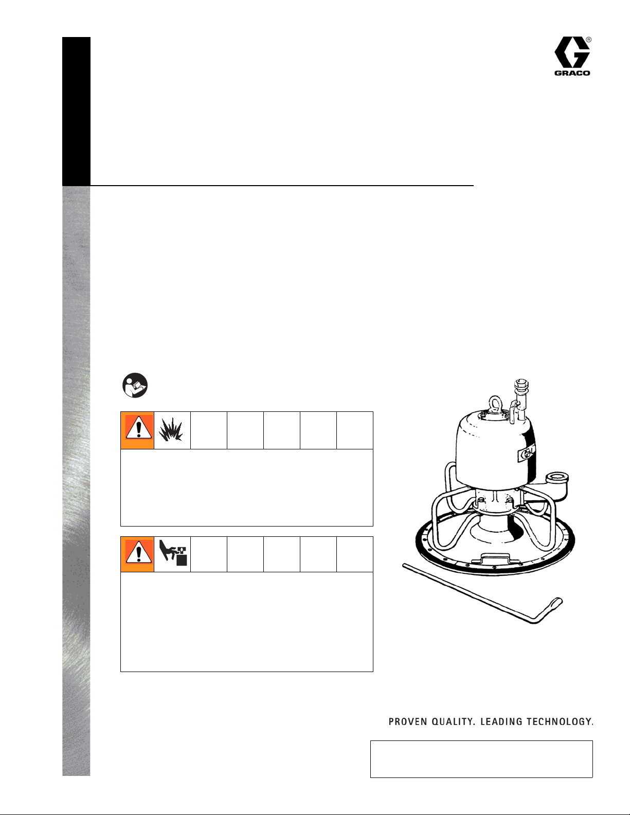
3:1 Ratio Bulldog
®
Transfer Pump
- For use in lubrication applications only -
Model: 205028
With inductor, guide bars and release bar
Model: 205148, Series E
Without inductor, guide bars and release bar
300 psi (2.1 MPa, 21 bar) Maximum Working Pressure
100 psi (0.7 MPa, 7 bar) Maximum Air Input Pressure
Important Safety Instructions
Read all warnings and instructions in this manual.
Save these instructions.
306642F
Use with lubrication applications only! This pump is
designed to be used for pumping non-corrosive and
non-abrasive lubricants and greases only. Any other use of
the pump can cause unsafe operating conditions and result
in component rupture, fire or explosion, which can cause
serious bodily injury.
Priming Piston Hazard
This pump has a priming piston which extends below the
foot valve during operation. This piston could pinch or
amputate your fingers or hands as it moves up, into the cylinder. To reduce the risk of injury, keep your fingers and
hands and all tools away from the priming piston during
operation and whenever the air and fluid pressure in the
pump is not fully relieved.
ti10550a
Graco Inc. P.O. Box 1441 Minneapolis, MN 55440-1441
Copyright 1958, Graco Inc. is registered to I.S. EN ISO 9001
Page 2
Warnings
Warnings
The following warnings are for the setup, use, grounding, maintenance, and repair of this equipment. The exclamation point symbol alerts you to a general warning and the hazard symbol refers to procedure-specific risk. Refer back to these warnings. Additional, product-specific warnings may be found throughout the body of this manual where applicable.
WARNING
FIRE AND EXPLOSION HAZARD
When flammable fluids are present in the work area, such as gasoline and windshield wiper fluid, be aware that
flammable fumes can ignite or explode. To help prevent fire and explosion:
• Use equipment only in well ventilated area.
• Eliminate all ignition sources, such as cigarettes and portable electric lamps.
• Keep work area free of debris, including rags and spilled or open containers of solvent and gasoline.
• Do not plug or unplug power cords or turn lights on or off when flammable fumes are present.
• Ground all equipment in the work area.
• Use only grounded hoses.
• If there is static sparking or you feel a shock, stop operation immediately. Do not use equipment until you
identify and correct the problem.
• Keep a working fire extinguisher in the work area.
EQUIPMENT MISUSE HAZARD
Misuse can cause death or serious injury.
• Do not operate the unit when fatigued or under the influence of drugs or alcohol.
• Do not exceed the maximum working pressure or temperature rating of the lowest rated system component.
See Technical Data in all equipment manuals.
• Use fluids and solvents that are compatible with equipment wetted parts. See Technical Data in all equipment
manuals. Read fluid and solvent manufacturer’s warnings. For complete information about your material,
request MSDS forms from distributor or retailer.
• Check equipment daily. Repair or replace worn or damaged parts immediately with genuine manufacturer’s
replacement parts only.
• Do not alter or modify equipment.
• Use equipment only for its intended purpose. Call your distributor for information.
• Route hoses and cables away from traffic areas, sharp edges, moving parts, and hot surfaces.
• Do not kink or over bend hoses or use hoses to pull equipment.
• Keep children and animals away from work area.
• Comply with all applicable safety regulations.
ELECTRIC SHOCK HAZARD
Improper grounding, setup, or usage of the system can cause electric shock.
• Turn off and disconnect power at main switch before disconnecting any cables and before servicing
equipment.
• Connect only to grounded power source.
• All electrical wiring must be done by a qualified electrician and comply with all local codes and
regulations.
PRESSURIZED EQUIPMENT HAZARD
Fluid from the gun/dispense valve, leaks, or ruptured components can splash in the eyes or on skin and cause serious injury.
• Follow Pressure Relief Procedure in this manual, when you stop spraying and before cleaning, checking, or
servicing equipment.
• Tighten all fluid connections before operating the equipment.
• Check hoses, tubes, and couplings daily. Replace worn or damaged parts immediately.
MOVING PARTS HAZARD
Moving parts can pinch or amputate fingers and other body parts.
• Keep clear of moving parts.
• Do not operate equipment with protective guards or covers removed.
• Pressurized equipment can start without warning. Before checking, moving, or servicing equipment, follow the
Pressure Relief Procedure in this manual. Disconnect power or air supply.
2 306642F
Page 3
Installation
Grounding
In a low pressure air spray system, static sparking is
generally not a problem; however some simple precautions should be taken to reduce the risk. Check your
local code for detailed grounding instructions for your
area and type of equipment. Ground all equipment.
Grounding reduces the risk of static and electric shock
by providing an escape wire for the electrical current
due to static build up or in the event of a short circuit.
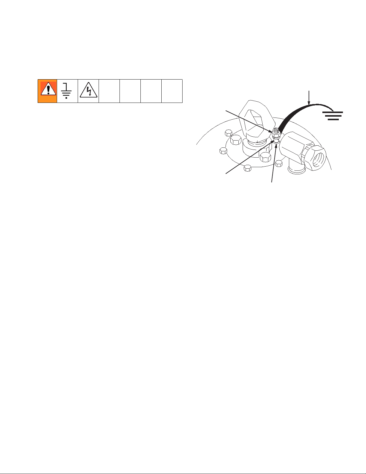
Installation
(c)
(a)
(b)
• Pump: (F
plied). Loosen grounding lug locknut (a) and washer
(b). Insert one end of ground wire (c) into the slot in
the lug (d). Tighten locknut securely. Connect other
end of wire to a true earth ground.
IG. 1) Use ground wire and clamp (sup-
(d)
F
IG. 1
• Air Compressor: according to manufacturer’s recommendations.
• Object being sprayed: according to local code.
• Fluid supply container: according to local code.
• All solvent pails used when flushing: according to
local code.
Only use conductive, metal pails. Do not place the
pail on a non-conductive surface such as paper or
cardboard, which interrupts the grounding continuity.
• To maintain grounding continuity when flushing or
relieving pressure, always hold metal part of the dispenser firmly to the side of a grounded metal pail,
then squeeze trigger.
306642F 3
Page 4
Installation
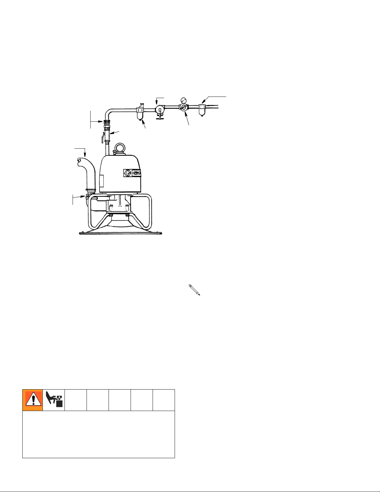
Air and Transfer Lines (FIG. 2)
The typical installation shown in FIG. 2 is only provided as a guide for selecting and installing required and optional
accessories. Be sure all air and fluid accessories are properly sized for your system and are compatible with the fluid
you are pumping. Contact your Graco representative for assistance in designing a transfer system to suit your specific needs.
Air inlet
3/4 npsm(f)
swivel
F
2” npt
outlet
ti0551a
F
IG. 2
• 3/4 in. ID Air Supply Line
• 3/4 npt(f) Air Inlet Swivel
C
E
D
B
A
Key:
A Air Line Filter
B Air Regulator
C Air Runaway Valve
D Air Line Oiler
E Bleed-type Master Air Valve
F Outlet Hose
• Install Transfer Hose (F) to the 2 in. npt(f) pump
outlet and tighten securely.
• On the Air Supply Line install:
• Air Filter (A) to remove harmful dirt and mois-
ture from the compressed air supply
• Air Regulator (B) to control pump speed
• Air Runaway Valve (C) to stop the pump auto-
matically if the supply container is empty.
• Air Line Oiler (D) for automatic air motor lubri-
cation
• Bleed-type master air valve (E): required in your
system to relieve air trapped between it and the air
motor when the valve is closed.
Never operate this pump with the bleed-type master air
valve (E) (supplied with the air motor) removed. When
closed, this valve relieves air trapped between it and
the air motor. Trapped air can cause the pump to cycle
unexpectedly and cause serious bodily injury from
moving parts.
For air requirements and additional Technical Data
see page 10.
Install the Pump
1. Remove cover from a full, open head drum of lubricant.
2. To help eliminate air pockets, which is essential for
good priming, smooth surface of the lubricant with a
straight edge until it is level.
3. Lift pump from the inductor plate and wipe bottom of
plate clean.
4. Press inductor plate down onto the lubricant. Rock
plate back and forth to firmly seat it and to exhaust
air trapped under the plate. Continue with this
motion until some lubricant is forced up into the
neck of the inductor plate.
5. Place pump on the inductor plate.
4 306642F
Page 5

Operation
Operation
Pressure Relief Procedure
The system pressure must be manually relieved to prevent the system from starting accidentally, which could
cause moving parts to pinch or amputate your fingers.
To reduce the risk for injury, always follow this procedure whenever you:
• are instructed to relieve the pressure
• check or service any part of the pump or system.
1. Shut off main air supply.
2. Close the air regulator and bleed-type master air
valve.
3. Loosen a fluid fitting near the pump outlet to relieve
fluid pressure.
Clearing Obstructions
KEEP YOUR FINGERS AND HANDS AWAY FROM
THE PRIMING PISTON! The priming piston, located
at the pump intake, could pinch or amputate your fingers as it moves into the intake cylinder.
1. Always relieve pressure, page 5, before attempting
to clear any obstructions.
2. Disconnect Air Hose. Grip 1-3/4 inch hex in the center of the piston to unscrew it.
Removing Inductor Plate from Drum
Reference numbers and letters in parentheses in
the text refer to the callouts in F
IG. 3.
Startup
Reference numbers and letters in parentheses in
the text refer to the callouts in the F
1. Turn on the main air supply.
2. Open Air Valve (E) and slowly open the Air Regulator (B) until the pump is running smoothly. Always
use the lowest pressure necessary to deliver lubricant at the desired quantity.
CAUTION
Do not let the pump run dry. A dry pump quickly
speeds up and may damage itself. If the pump is running erratically or speeds up suddenly, relieve pump
pressure following Pressure Relief Procedure
(page 5) and change the lubricant drum. Use an Air
Runaway Valve (D) to shut off the pump automatically
when the drum is empty.
3. Shut off the pump and relieve pressure, page 5,
when the pump is not in use.
IG. 2.
16
ti0552a
FIG. 3
1. Relieve pressure, page 5.
2. Lift pump off inductor plate.
3. Insert the release bar (15) into the neck of the plate
and position it so that by applying leverage, the vacuum seal which formed beneath the plate, is broken.
4. Remove the plate.
306642F 5
Page 6

Troubleshooting
Troubleshooting
L
Problem Cause Solution
Pump doesn’t operate Insufficient air supply Be sure adequate volume of air is
supplied to pump. See Technical
Data on back cover.
Check for restriction in air line or
closed valves or regulators.
Check valve plate held closed by
obstruction
Damaged air motor See motor manual 307049, supplied.
Air motor operates but lubricant flow
is low
Erratic pump operation Worn, damaged or obstructed check
Leakage from weep hole Worn or damage throat packings Replace v-packings and glands. See
Empty lubricant drum Change drums.
Insufficient air supply Increase air pressure. Do not exceed
valve plate
Follow the Pressure Relief Procedure
above. Remove pump from inductor
plate and clean pump intake.
100 psi (.7 MPa, 7 bar)
Follow the Pressure Relief Proce-
dure, page 5. Remove pump from
inductor plate and clean and/or repair
intake.
page 7.
6 306642F
Page 7

Repair
Repair
Throat Packing Repair (FIG. 4)
V-Packin g
Must Face
Lips of
V-Packin gs
Must Face
FIG. 4
E
Lips of
L
Down
Up
P
B
• The throat packings are actually located in the
base of the air motor, but function as the throat
packings for the pump. To identify part numbers
and order repair parts, refer to parts list page
for air motor 208357 in instruction manual
307049, supplied.
C
• Reference numbers and letters in parentheses
in the text refer to the callouts in F
IG. 4 and
Parts List page 9.
F
H
J
D
17
4, 2
19
14
A
13
Weep
Hole
K
M
N
G
1. Relieve pressure, page 5.
2. Disconnect air hose and transfer hose. Remove air
inlet fittings.
3. Remove pump from inductor plate (20).
4. Unscrew priming piston (13) from connecting tube
(A). The priming piston has a 1-3/4 in. hex in the
center.
5. Remove nuts and lock washers (4, 2) holding pump
guides (12) and collars (17). Remove these parts.
6. Pull intake cylinder (19) straight down.
7. Remove screws (P) and air motor shield (B).
8. Remove screws and washers holding air motor cylinder (C) to base (D). Pull base straight off, being
careful not to damage smooth surfaces of connecting tube and cylinder.
9. Inspect v-packing (E) in base. If it is worn or damaged, remove it. Grease new packing and carefully
tuck it into base. Be sure washer (F) is in place in
base.
10. Unscrew packing retainer (G) and remove the
spring and packings.
11. Clean all parts thoroughly and inspect for wear or
damage. Replace all packings and glads and other
parts as necessary.
12. Grease all parts thoroughly with light, waterproof
grease.
306642F 7
Page 8

Repair
13. One at a time, install a washer (H), bearing (J),
female gland (K), four leather v-packings (L) with
lips of the v-packings facing out of the base, male
gland (M), spring (N) and retainer (G).
14. Turn retainer in about 3 times.
15. Lubricate connecting tube (A) with light, waterproof
grease.
16. Carefully push base onto tube and secure it to the
cylinder with screws and washer. Then tighten packing retainer (G) snugly.
17. Inspect o-ring (18) in air motor base. Replace it if it
is damaged. Grease new o-ring before installing it.
18. Install air motor shield and screws.
19. Install check valve plate (14), cylinder (19) collars
(17), and pump guides (12). Secure with lock washers (2) and nuts (4) on screws (5).
20. Screw priming piston (13) onto connecting tube (A).
Pump Intake Repair (FIG. 4)
1. Relieve pressure, page 5.
2. Disconnect air hose from motor.
3. Remove pump from inductor plate.
4. Remove nuts and lock washers (4, 2) holding pump
guides (12). Remove collars (17).
5. Pull cylinder (19) straight down.
6. Unscrews priming piston (13) from connecting tube
(A). The priming piston has a 1-3/4 in. hex in the
center.
7. Remove check valve plate (14).
8. Clean all parts thoroughly and inspect for wear or
damage. Replace parts as necessary and
reassemble.
8 306642F
Page 9

Parts
21
2” npt(f)
fluid outlet
11
18
10
Parts
Model 205148
3/4” npt air inlet
8
1, 3
5
Pump, 3:1 Bulldog
Ref.
No. Part No. Description Qty.
2 100133 LOCKWASHER, spring, 3/8” 4
4 100340 NUT, hex; 3/8-16 4
5 100454 CAPSCREW, hex hd; 3/8-16x3” 4
8 101864 CAPSCREW, soc hd; 5/16-18 x 1” 4
10 162841 O-RING 1
11 162842 ADAPTER 1
13 162844 PLATE, priming shovel 1
14 162846 PLATE, check valve 1
17 162933 COLLAR, cylinder mounting 2
18 162934* O-RING 1
19 162936 CYLINDER, pump intake 1
21 208357 AIR MOTOR (see manual 307049
for parts)
* Recommended “tool box” spare parts. Keep on
hand.
1
ti10555a
FIG. 5
12
17
14
16 Follow Plate Release Bar
6
9
20
13
19
4, 2
15
Model 205028
Pump, 3:1 Bulldog with inductor
Ref.
No. Part No. Description Qty.
1 100057 SCREW, hex hd cap; 5/16-18 x 3/4” 4
3 100214 LOCKWASHER, spring 5/16 4
6 100799 SCREW, rd hd mach; 1/4-20 x 1/2” 18
9 161288 SEGMENT, full barrel, 400 lb 6
12 162843 GUIDE, pump 4
15 162852* WIPER, follow plate 1
16 162853 BAR, follow plate release 1
20 205144 PLATE, follow 1
* Recommended “tool box” spare parts. Keep on
hand.
306642F 9
Page 10

Technical Data
Technical Data
Fluid Pressure Ratio. . . . . . . . . . . . . . . . . . . . . . . . . . . . . 3:1
Air Pressure Range . . . . . . . . . . . . . . . . . . . . . . . . . . . . . 40 - 100 psi (0.28 - 0.7 MPa, 2.8 - 7 bar)
Maximum Working Fluid Pressure . . . . . . . . . . . . . . . . . . 300 psi (2.1 MPa, 21 bar)
Maximum Recommended Pump Speed . . . . . . . . . . . . . 60 cycles/minute
Air Motor Effective Diameter . . . . . . . . . . . . . . . . . . . . . . 7 in. (178 mm)
Stroke. . . . . . . . . . . . . . . . . . . . . . . . . . . . . . . . . . . . . . . . 4-3/4 in. (120 mm)
Air Inlet Size . . . . . . . . . . . . . . . . . . . . . . . . . . . . . . . . . . . 3/4 npsm(f) swivel
Fluid Outlet Size. . . . . . . . . . . . . . . . . . . . . . . . . . . . . . . . 2 in. npt(f)
Fluid Inlet . . . . . . . . . . . . . . . . . . . . . . . . . . . . . . . . . . . . . Priming Piston
Height. . . . . . . . . . . . . . . . . . . . . . . . . . . . . . . . . . . . . . . . 28.25 in. (718 mm)
Inductor Diameter. . . . . . . . . . . . . . . . . . . . . . . . . . . . . . . 22.5 in. (570 mm)
Weight . . . . . . . . . . . . . . . . . . . . . . . . . . . . . . . . . . . . . . . 121 lb (53 Kg) approximate
Wetted Parts . . . . . . . . . . . . . . . . . . . . . . . . . . . . . . . . . . Aluminum, steel, Buna-N, Leather, Brass, neoprene/duck
10 306642F
Page 11

Notes
Notes
306642F 11
Page 12

Graco Warranty and Disclaimers
Graco Warranty and Disclaimers
Warranty
Graco warrants all equipment manufactured by it and bearing its name to be free from defects in material and workmanship on the date of sale by an authorized Graco distributor to the original purchaser for use. As purchaser’s sole
remedy for breach of this warranty, Graco will, for a period of twelve months from the date of sale, repair or replace
any part of the equipment proven defective. This warranty applies only when the equipment is installed, operated and
maintained in accordance with Graco’s written recommendations.
This warranty does not cover, and Graco shall not be liable for, any malfunction, damage or wear caused by faulty
installation, misapplication, abrasion, corrosion, inadequate or improper maintenance, negligence, accident, tampering, or substitution of non-Graco component parts. Nor shall Graco be liable for malfunction, damage or wear caused
by incompatibility with Graco equipment of structures, accessories, equipment or materials not supplied by Graco, or
improper design, manufacture, installation, operation or maintenance of structures, accessories, equipment or materials not supplied by Graco.
This warranty is conditioned upon the prepaid return of the equipment claimed to be defective to an authorized Graco
distributor for verification of the claim. If the claimed defect is verified, Graco will repair or replace free of charge any
defective parts. The equipment will be returned to the original purchaser transportation prepaid. If inspection of the
equipment does not disclose any defect in material or workmanship, repairs will be made at a reasonable charge,
which charges may include the costs of parts, labor and transportation.
Disclaimers and Limitations
The terms of this warranty constitute purchaser’s sole and exclusive remedy and are in lieu of any other warranties
(express or implied), including warranty of merchantability or warranty of fitness for a particular purpose, and of any
non-contractual liabilities, including product liabilities, based on negligence or strict liability. Every form of liability for
direct, special or consequential damages or loss is expressly excluded and denied. In no case shall Graco’s liability
exceed the amount of the purchase price. Any action for breach of warranty must be brought within two (2) years of
the date of sale.
Equipment Not Covered by Graco Warranty
Graco makes no warranty, and disclaims all implied warranties of merchantability and fitness for a particular purpose,
with respect to accessories, equipment, materials, or components sold but not manufactured by Graco. These items
sold, but not manufactured by Graco (such as electric motors, switches, hose, etc.) are subject to the warranty, if any,
of their manufacturer. Graco will provide purchaser with reasonable assistance in making any claim for breach of
these warranties.
All written and visual data contained in this document reflects the latest product information available at the time of publication.
Graco reserves the right to make changes at any time without notice.
This manual contains English. MM 306642
Graco Headquarters: Minneapolis
International Offices: Belgium, China, Japan, Korea
GRACO INC. P.O. BOX 1441 MINNEAPOLIS, MN 55440-1441
12 306642F
www.graco.com
12/1958, Revised 6/2007
 Loading...