

Page 1
Instructions-Parts
Plural Component, Impingement Mix
Mechanical Purge Spray Gun
For use with non-flammable foam and polyurea.
Not for use in explosive atmospheres.
3500 psi (24.2 MPa, 242 bar) Maximum Fluid Working Pressure
80-130 psi (0.55-0.9 MPa, 5.5-9.1 bar) Air Inlet Pressure Range
200°F (94°C) Maximum Fluid Temperature
Important Safety Instructions
Read all warnings and instructions in this manual.
Save these instructions.
309856P
US Patent Number 7,036,171
D479,305
Korean Patent 338185
Australian Patent Number 152610
2004230905
EP 1610904
TI3840a
Page 2

Contents
Manual Conventions . . . . . . . . . . . . . . . . . . . . . . . . 3
List of Models/Selection Guide . . . . . . . . . . . . . . . 4
Standard Round Pattern Guns . . . . . . . . . . . . . . 4
Standard Flat Pattern Guns . . . . . . . . . . . . . . . . 5
Direct Impingement Round Pattern Guns . . . . . . 6
Direct Impingement Flat Pattern Guns . . . . . . . . 7
Direct Impingement Flat Pattern Guns . . . . . . . . 8
Four-Hose Gun . . . . . . . . . . . . . . . . . . . . . . . . . . 8
Overall View . . . . . . . . . . . . . . . . . . . . . . . . . . . . . . 11
Isocyanate Hazard . . . . . . . . . . . . . . . . . . . . . . . . . 12
Keep A and B Components Separate . . . . . . . . . 12
Grounding . . . . . . . . . . . . . . . . . . . . . . . . . . . . . . . 12
Piston Safety Lock . . . . . . . . . . . . . . . . . . . . . . . . 12
Loss of Air Pressure . . . . . . . . . . . . . . . . . . . . . . . 12
Setup . . . . . . . . . . . . . . . . . . . . . . . . . . . . . . . . . . . . 13
Adjust Purge Rod . . . . . . . . . . . . . . . . . . . . . . . . . 15
Adjust Flat CeramTip . . . . . . . . . . . . . . . . . . . . . . 16
Shutdown . . . . . . . . . . . . . . . . . . . . . . . . . . . . . . . . 17
Daily Shutdown . . . . . . . . . . . . . . . . . . . . . . . . . 17
Shutdown for More than a Day . . . . . . . . . . . . . 17
Pressure Relief Procedure . . . . . . . . . . . . . . . . . . 18
Optional Configurations . . . . . . . . . . . . . . . . . . . . 19
Optional Fluid Manifold Position . . . . . . . . . . . . 19
Optional Hose Position . . . . . . . . . . . . . . . . . . . 20
Maintenance . . . . . . . . . . . . . . . . . . . . . . . . . . . . . . 21
Supplied Tool Kit . . . . . . . . . . . . . . . . . . . . . . . . 21
Keep Gun Clean . . . . . . . . . . . . . . . . . . . . . . . . 21
As Needed . . . . . . . . . . . . . . . . . . . . . . . . . . . . 21
Daily . . . . . . . . . . . . . . . . . . . . . . . . . . . . . . . . . 21
Weekly to Monthly . . . . . . . . . . . . . . . . . . . . . . . 21
Flush Gun . . . . . . . . . . . . . . . . . . . . . . . . . . . . . 22
Clean Outside of Gun . . . . . . . . . . . . . . . . . . . . 22
Clean Air Cap . . . . . . . . . . . . . . . . . . . . . . . . . . 22
Clean Muffler . . . . . . . . . . . . . . . . . . . . . . . . . . . 22
Clean Fluid Manifold . . . . . . . . . . . . . . . . . . . . . 22
Clean Slip-Fit Polycarballoy Mix Module . . . . . . 23
Clean CeramTip . . . . . . . . . . . . . . . . . . . . . . . . 26
Stuck Purge Rod . . . . . . . . . . . . . . . . . . . . . . . . 27
Clean Purge Rod . . . . . . . . . . . . . . . . . . . . . . . 27
Adjust Front Rod Seal . . . . . . . . . . . . . . . . . . . . 28
Adjust Rear Rod Seal . . . . . . . . . . . . . . . . . . . . 29
Troubleshooting . . . . . . . . . . . . . . . . . . . . . . . . . . . 30
Theory of Operation . . . . . . . . . . . . . . . . . . . . . 32
Cutaway View . . . . . . . . . . . . . . . . . . . . . . . . . . 33
Repair . . . . . . . . . . . . . . . . . . . . . . . . . . . . . . . . . . . 34
Tools Required . . . . . . . . . . . . . . . . . . . . . . . . . 34
Lubrication . . . . . . . . . . . . . . . . . . . . . . . . . . . . 34
Replace CeramTip . . . . . . . . . . . . . . . . . . . . . . 34
Disassemble Front End . . . . . . . . . . . . . . . . . . . 35
Reassemble Front End . . . . . . . . . . . . . . . . . . . 36
Slip-Fit Polycarballoy Mix Module . . . . . . . . . . . 38
Rear Rod Seal . . . . . . . . . . . . . . . . . . . . . . . . . . 40
Check Valves . . . . . . . . . . . . . . . . . . . . . . . . . . . 41
Piston and Purge Rod . . . . . . . . . . . . . . . . . . . . 42
Piston Safety Lock . . . . . . . . . . . . . . . . . . . . . . . 44
Air Valve . . . . . . . . . . . . . . . . . . . . . . . . . . . . . . 44
Notes . . . . . . . . . . . . . . . . . . . . . . . . . . . . . . . . . . . . 45
Parts . . . . . . . . . . . . . . . . . . . . . . . . . . . . . . . . . . . . 46
Slip-Fit Polycarballoy Mix Module Kits . . . . . . . . 48
CeramTip Kits . . . . . . . . . . . . . . . . . . . . . . . . . . 50
Drill Bit Kits . . . . . . . . . . . . . . . . . . . . . . . . . . . . 51
Gun Repair Kits . . . . . . . . . . . . . . . . . . . . . . . . . 52
Check Valve Filter Screen Kits (10 per kit) . . . . 52
Accessories . . . . . . . . . . . . . . . . . . . . . . . . . . . . . . 53
Gun Cover . . . . . . . . . . . . . . . . . . . . . . . . . . . . . 53
Fusion Gun Lubricant Kit . . . . . . . . . . . . . . . . . . 53
Tip Cleanout Tool . . . . . . . . . . . . . . . . . . . . . . . . 53
Gun Cleaning Kit . . . . . . . . . . . . . . . . . . . . . . . . 53
Circulation Manifold . . . . . . . . . . . . . . . . . . . . . . 53
Flushing Manifold . . . . . . . . . . . . . . . . . . . . . . . 53
Solvent Flush Kits . . . . . . . . . . . . . . . . . . . . . . . 53
Solvent Flush Pail Kit . . . . . . . . . . . . . . . . . . . . . 54
Hose Adapter Kits . . . . . . . . . . . . . . . . . . . . . . . 54
Pour Nozzle Kit . . . . . . . . . . . . . . . . . . . . . . . . . 54
Technical Data . . . . . . . . . . . . . . . . . . . . . . . . . . . . 55
Graco Standard Warranty . . . . . . . . . . . . . . . . . . . 56
Graco Information . . . . . . . . . . . . . . . . . . . . . . . . . 56
2 309856P
Page 3
Manual Conventions
Warning Caution
Manual Conventions
WARNING
A warning alerts you to possible serious injury or
death if you do not follow instructions.
Symbols, such as fluid injection (shown), alert you to a
specific hazard and direct you to read the indicated
hazard warnings on pages 9-10.
CAUTION
A caution alerts you to possible equipment damage or
destruction if you do not follow instructions.
Note
A note indicates additional helpful information.
309856P 3
Page 4
List of Models/Selection Guide
List of Models/Selection Guide
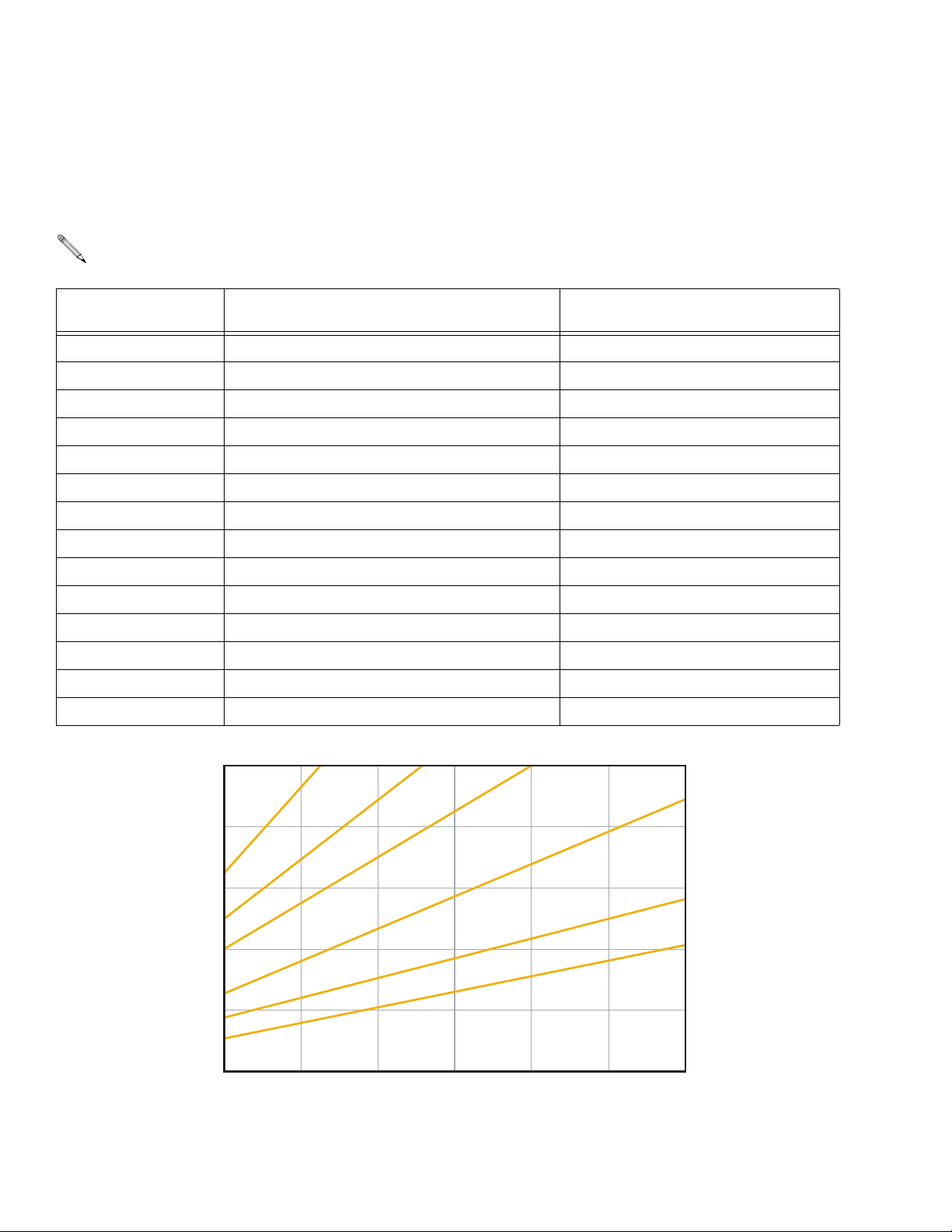
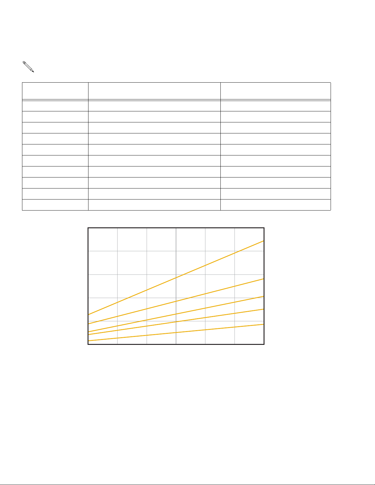
Standard Round Pattern Guns
Use only these mix module/tip combinations.
Gun Part No., Series Slip-Fit™ Polycarballoy™ Mix Module Part No.,
see page 48 for numbering code
Round CeramTip™ Part No.,
see page 50 for numbering code
247211, A MR3535 RTM030
247212, A MR3535 RTM040
247213, A MR3535 RTM055
247218, A MR4747 RTM040
247219, A MR4747 RTM055
247225, A MR5757 RTM055
247226, A MR5757 RTM070
247231, A MR6666 RTM070
247232, A MR6666 RTM080
247233, A MR6666 RTM090
247239, A MR8282 RTM090
247240, A MR8282 RTM100
247245, A MR9494 RTM100
247246, A MR9494 RTM110
5.0
(18.9)
4.0
(15.1)
3.0
(11.4)
2.0
(7.6)
1.0
(3.8)
9
R
M
0
1
1
M
T
R
/
4
9
4
2
8
R
M
0
09
M
T
R
/
2
8
6
6
6
R
M
0
8
0
TM
R
/
6
7
5
7
5
R
M
4
R
M
R
M
0
7
0
M
T
R
/
5
5
0
M
T
R
/
7
4
7
0
4
0
TM
R
/
5
3
5
3
FLOW RATE in gpm (lpm)*
* To calculate flow in lb/min, multiply gpm rate by 10.
Example: 2 gpm x 10 = 20 lb/min.
0
800
(5.6, 56)
1250
(8.7, 87)
1700
(11.9, 119)
2150
(15.0, 150)
2600
(18.2, 182)
3050
(21.3, 213)
3500
(24.5, 245)
PRESSURE in psi (MPa, bar)
4 309856P
Page 5
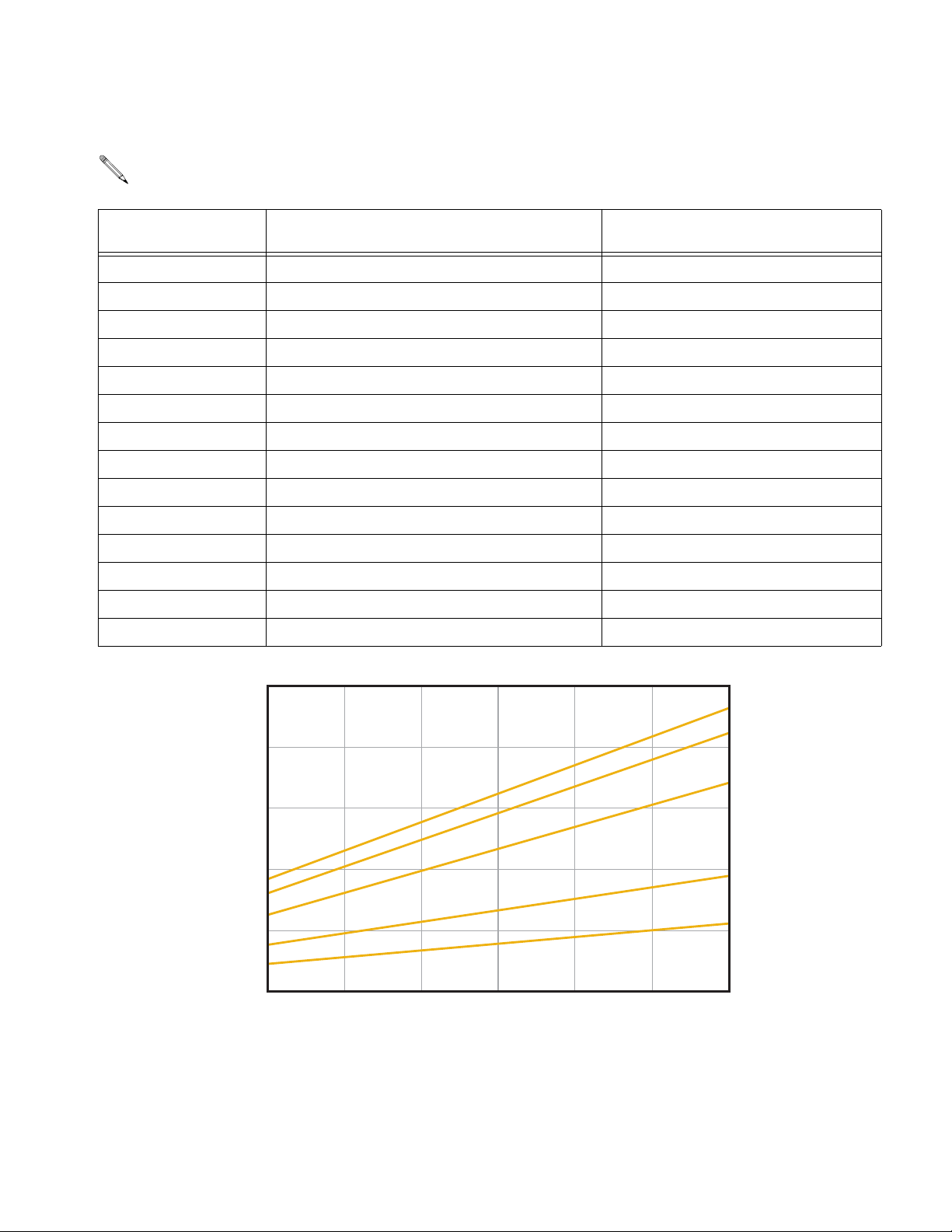
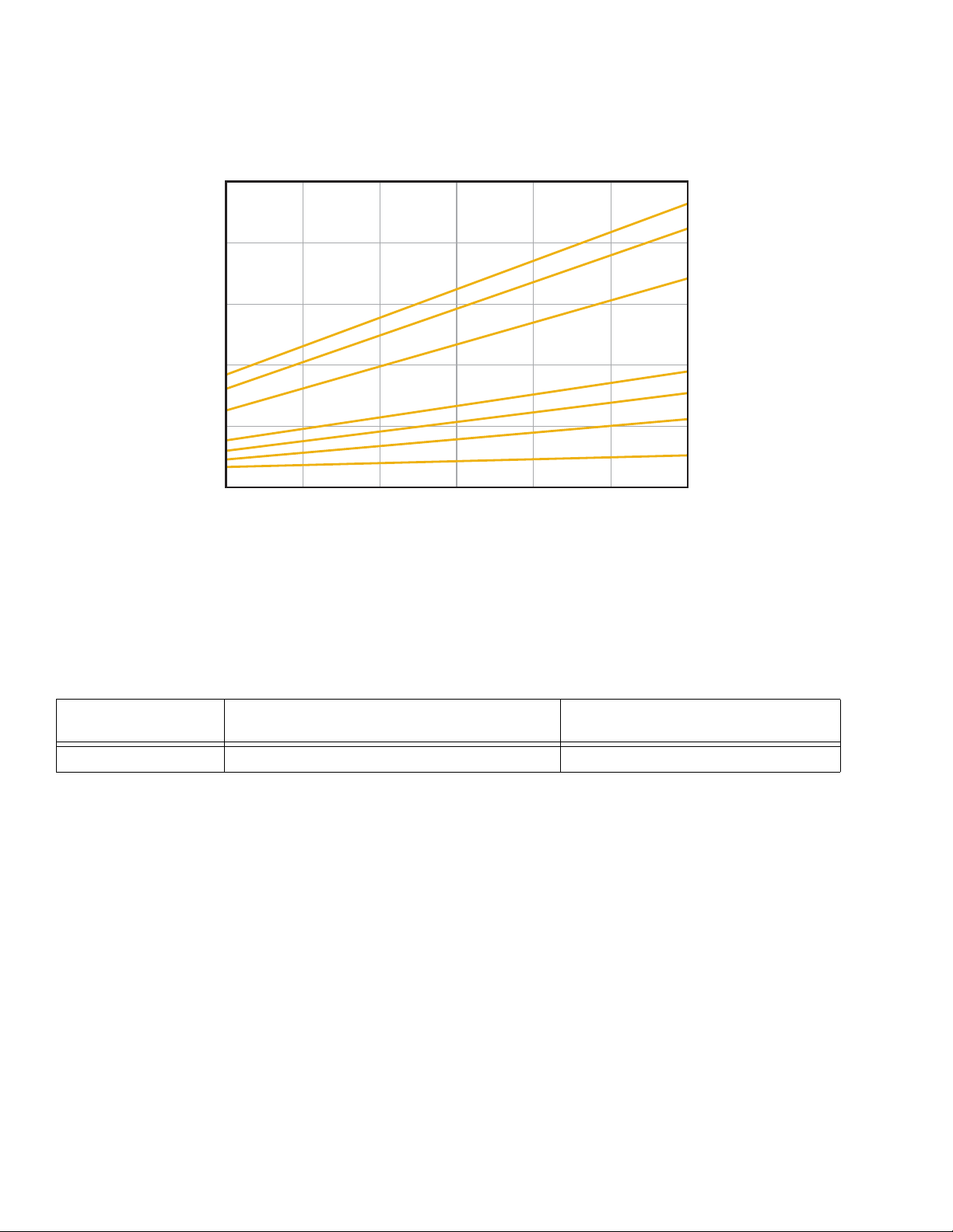
Standard Flat Pattern Guns
Use only these mix module/tip combinations.
List of Models/Selection Guide
Gun Part No., Series Slip-Fit™ Polycarballoy™ Mix Module Part No.,
see page 48 for numbering code
Flat CeramTip™ Part No.,
see page 50 for numbering code
247257, A MF1818 FTM317
247258, A MF1818 FTM424
247265, A MF2929 FTM424
247266, A MF2929 FTM438
247267, A MF2929 FTM624
247273, A MF3535 FTM438
247274, A MF3535 FTM624
247275, A MF3535 FTM638
247281, A MF4747 FTM624
247282, A MF4747 FTM638
247283, A MF4747 FTM838
247289, A MF5757 FTM638
247290, A MF5757 FTM838
247291, A MF5757 FTM848
FLOW RATE in gpm (lpm)*
2.0
(7.6)
1.6
(6.0)
1.2
(4.5)
0.8
(3.0)
0.4
(1.5)
* To calculate flow in lb/min, multiply gpm rate by 10.
Example: 2 gpm x 10 = 20 lb/min.
0
800
(5.6, 56)
1250
(8.7, 87)
5
7
5
F
M
4
F
M
M
1700
(11.9, 119)
2150
(15.0, 150)
2600
(18.2, 182)
PRESSURE in psi (MPa, bar)
F
/
7
4
7
3
F
M
3
6
M
T
M
T
F
/
7
F
/
5
3
5
2
9
2
F
8
1
F
M
(21.3, 213)
8
6
T
9
1
8
3
6
M
T
F
/
F
/
8
3050
3
M
T
8
4
M
4
2
4
2
4
(24.5, 245)
3500
309856P 5
Page 6
List of Models/Selection Guide
Direct Impingement Round Pattern Guns
Use only these mix module/tip combinations.
Gun Part No., Series Slip-Fit™ Polycarballoy™ Mix Module Part No.,
see page 48 for numbering code
Round CeramTip™ Part No.,
see page 50 for numbering code
247003, A XR2323 RTM040
247006, A XR2929 RTM030
247007, A XR2929 RTM040
247011, A XR3535 RTM030
247012, A XR3535 RTM040
247013, A XR3535 RTM055
247018, A XR4747 RTM040
247019, A XR4747 RTM055
247025, A XR5757 RTM055
247026, A XR5757 RTM070
5.0
(18.9)
0
7
0
M
4.0
(15.1)
R
X
T
R
/
/
7
5
7
5
FLOW RATE in gpm (lpm)*
* To calculate flow in lb/min, multiply gpm rate by 10.
3.0
(11.4)
2.0
(7.6)
1.0
(3.8)
Example: 2 gpm x 10 = 20 lb/min.
0
800
(5.6, 56)
(8.7, 87)
1250
1700
(11.9, 119)
2150
(15.0, 150)
2600
(18.2, 182)
PRESSURE in psi (MPa, bar)
7
4
R
X
R
X
9
2
R
X
3
2
R
X
(21.3, 213)
4
5
3
9
2
3
2
3050
5
5
0
M
T
R
/
7
0
4
0
TM
R
/
5
3
0
4
0
TM
R
/
0
4
0
M
T
R
/
3500
(24.5, 245)
6 309856P
Page 7

Direct Impingement Flat Pattern Guns
Use only these mix module/tip combinations.
List of Models/Selection Guide
Gun Part No., Series Slip-Fit™ Polycarballoy™ Mix Module Part No.,
see page 48 for numbering code
247050, A XF1313 FTM317
247051, A XF1313 FTM424
247057, A XF1818 FTM317
247058, A XF1818 FTM424
247061, A XF2323 FTM424
247062, A XF2323 FTM438
247063, A XF2323 FTM624
247065, A XF2929 FTM424
247066, A XF2929 FTM438
247067, A XF2929 FTM624
247073, A XF3535 FTM438
247074, A XF3535 FTM624
247075, A XF3535 FTM638
247081, A XF4747 FTM624
247082, A XF4747 FTM638
Flat CeramTip™ Part No.,
see page 50 for numbering code
247083, A XF4747 FTM838
247089, A XF5757 FTM638
247090, A XF5757 FTM838
247091, A XF5757 FTM848
247163, A XF2332 FTM438
309856P 7
Page 8
List of Models/Selection Guide
Direct Impingement Flat Pattern Guns
2.0
(7.6)
1.6
(6.0)
1.2
(4.5)
7
5
F
X
XF
XF
8
3
6
M
T
F
/
7
5
4
7
4
5
3
8
3
6
M
T
/F
7
8
3
6
M
T
/F
5
3
0.8
(3.0)
0.4
(1.5)
9
2
9
2
F
X
2
3
2
F
X
8
1
8
1
F
X
3
1
3
1
F
X
4
2
4
M
T
F
/
4
2
4
M
T
F
/
3
4
2
4
M
T
F
/
4
2
4
M
T
F
/
FLOW RATE in gpm (lpm)*
* To calculate flow in lb/min, multiply gpm rate by 10.
Example: 2 gpm x 10 = 20 lb/min.
0
800
(5.6, 56)
1250
(8.7, 87)
1700
(11.9, 119)
2150
(15.0, 150)
2600
(18.2, 182)
3050
(21.3, 213)
PRESSURE in psi (MPa, bar)
Four-Hose Gun
Wide Round Pattern Gun with Four-Hose Recirculating Gun Manifold
Gun Part No., Series Slip-Fit™ Polycarballoy™ Mix Module Part No.,
see page 48 for numbering code
249815, A XF2323 FTM438
Flat CeramTip™ Part No.,
see page 50 for numbering code
3500
(24.5, 245)
8 309856P
Page 9
Warning
WARNING
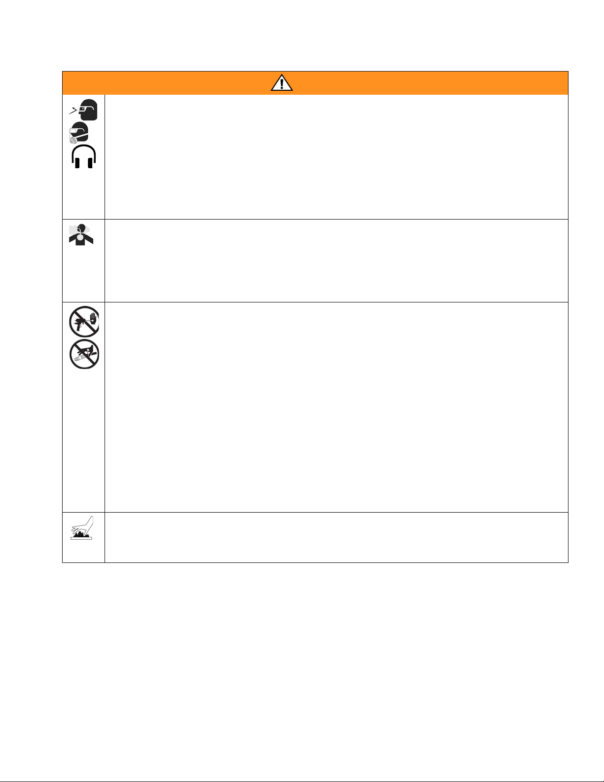
PERSONAL PROTECTIVE EQUIPMENT
You must wear proper protective equipment when operating, servicing, or when in the operating area of
the equipment to help protect you from serious injury, including eye injury, inhalation of toxic fumes,
burns, and hearing loss. This equipment includes but is not limited to:
• Protective eyewear
• Clothing and respirator as recommended by the fluid and solvent manufacturer
•Gloves
• Hearing protection.
TOXIC FLUID OR FUMES HAZARD
Toxic fluids or fumes can cause serious injury or death if splashed in the eyes or on skin, inhaled, or
swallowed.
• Read Material Safety Data Sheet (MSDS) to know the specific hazards of the fluids you are using.
• Store hazardous fluid in approved containers, and dispose of it according to applicable guidelines.
SKIN INJECTION HAZARD
High-pressure fluid from gun, hose leaks, or ruptured components will pierce skin. This may look like just
a cut, but it is a serious injury that can result in amputation. Get immediate surgical treatment.
• Do not point the gun at anyone or at any part of the body.
• Do not put your hand over the spray tip.
• Do not stop or deflect leaks with your hand, body, glove, or rag.
• Do not “blow back” fluid; this is not an air spray system.
• Follow Pressure Relief Procedure, page 18, when you stop spraying and before cleaning, check-
ing, or servicing equipment.
• Use lowest possible pressure when flushing, priming, or troubleshooting.
• Engage piston safety lock when not spraying.
• Tighten all fluid connections before operating the equipment.
• Check hoses, tubes, and couplings daily. Replace worn or damaged parts immediately. High pressure hose cannot be recoupled; replace the entire hose.
BURN HAZARD
Equipment surfaces and fluid that’s heated can become very hot during operation. To avoid severe
burns, do not touch hot fluid or equipment. Wait until equipment/fluid has cooled completely.
309856P 9
Page 10
Warning
WARNING
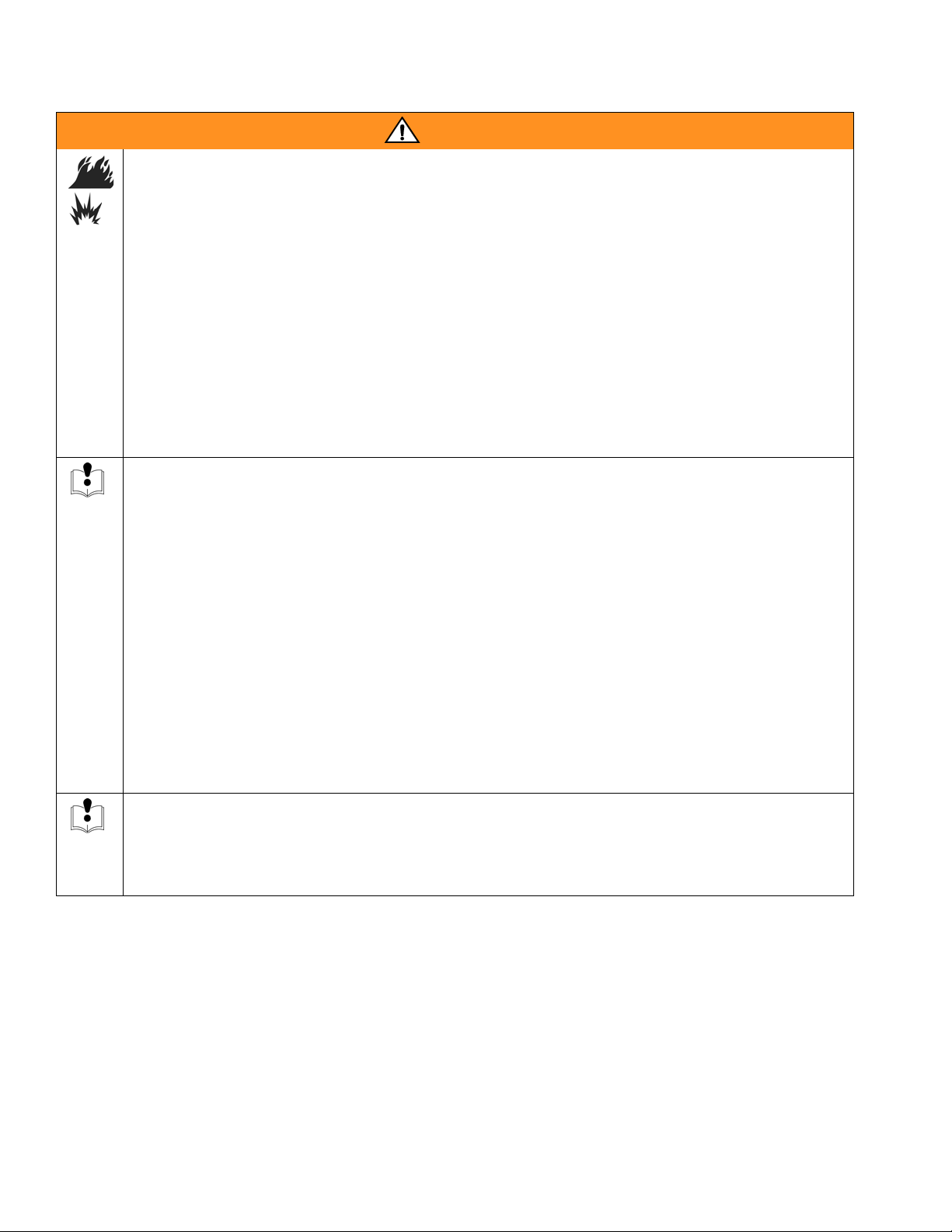
FIRE AND EXPLOSION HAZARD
Flammable fumes, such as solvent and paint fumes, in work area can ignite or explode. To help prevent
fire and explosion:
• Use equipment only in well ventilated area.
• Eliminate all ignition sources, such as pilot lights, cigarettes, portable electric lamps, and plastic drop
cloths (potential static arc).
• Do not plug or unplug power cords or turn lights on or off when flammable fumes are present.
• Keep the work area free of debris, including solvent, rags, and gasoline.
• Ground equipment and conductive objects. See Grounding, page 12.
• Hold gun firmly to side of grounded pail when triggering into pail.
• Use only grounded hoses.
• If there is static sparking or you feel a shock, stop operation immediately. Do not use equipment
until you identify and correct the problem.
EQUIPMENT MISUSE HAZARD
Misuse can cause serious injury or death.
• For professional use only.
• Use equipment only for its intended purpose. Call your Graco distributor for information.
• Read manuals, warnings, tags, and labels before operating equipment. Follow instructions.
• Check equipment daily. Repair or replace worn or damaged parts immediately.
• Do not alter or modify equipment. Use only Graco parts and accessories.
• Do not exceed the maximum working pressure or temperature rating of the lowest rated system
component. See Technical Data in all equipment manuals.
• Use fluids and solvents that are compatible with equipment wetted parts. See Technical Data in all
equipment manuals. Read fluid and solvent manufacturer’s warnings.
• Route hoses and cables away from traffic areas, sharp edges, moving parts, and hot surfaces.
• Do not use hoses to pull equipment.
• Comply with all applicable safety regulations.
PRESSURIZED ALUMINUM PARTS HAZARD
Do not use 1,1,1-trichloroethane, methylene chloride, other halogenated hydrocarbon solvents or fluids
containing such solvents in pressurized aluminum equipment. Such use can cause serious chemical
reaction and equipment rupture, and result in death, serious injury, and property damage.
10 309856P
Page 11
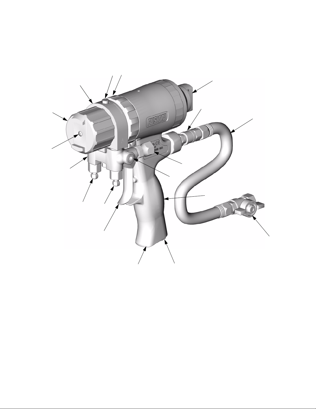
Overall View
F
C
M
Overall View
P
K
L
D
T
G
Key:
A A Side Fluid Valve (ISO)
B B Side Fluid Valve (RESIN)
CAir Cap
D Air Line Quick Coupler
EMuffler
F Fluid Housing
G Gun Fluid Manifold
H Handle
J Optional Air Inlet
K Cleanoff Air Valve
L Piston Safety Lock
M CeramTip (behind air cap)
R
N
H
AB
S
J
E
N Optional Fluid Inlets (A Side Shown)
P Lock Ring
R Fluid Inlet Swivels (A Side Shown)
S Trigger
T Gun Air Whip Hose
UAir Valve
U
TI3840a-1
309856P 11
Page 12
Isocyanate Hazard
Isocyanate Hazard
Spraying materials containing isocyanates creates
potentially harmful mists, vapors, and atomized particulates.
Read material manufacturer’s warnings and material
MSDS to know specific hazards and precautions
related to isocyanates.
Prevent inhalation of isocyanate mists, vapors, and
atomized particulates by providing sufficient ventilation in the work area. If sufficient ventilation is not
available, a supplied-air respirator is required for
everyone in the work area.
To prevent contact with isocyanates, appropriate personal protective equipment, including chemically
impermeable gloves, boots, aprons, and goggles, is
also required for everyone in the work area.
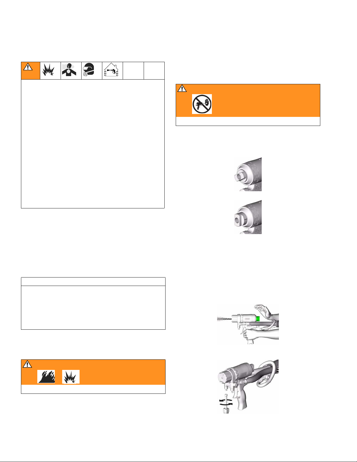
Piston Safety Lock
Engage piston safety lock whenever you stop spraying, to avoid accidental triggering.
WARNING
Read warnings, page 9.
To engage piston safety lock: push knob in and turn
clockwise. When engaged, piston safety lock allows
some purge rod movement but shuts off fluid flow and
gun cannot spray. To disengage piston safety lock:
TI3850a
push knob in and turn counterclockwise until it pops out.
Keep A and B Components Separate
CAUTION
To prevent cross-contamination of the gun’s wetted
parts, do not interchange A component (isocyanate)
and B component (resin) parts. The gun is shipped
with the A side on the left. The fluid manifold, fluid
housing, check valve cartridge, and mix module are
marked on the A side.
Grounding
WARNING
Read warnings, page 10.
TI3849a
Loss of Air Pressure
In event of loss of air pressure while gun is triggered,
gun will continue to spray. To shut off gun, do one of the
following:
• Push hard or hit end of safety lock, to engage piston
safety lock.
TI4022a
• Close fluid valves A and B.
Check your local electrical code and proportioner manual for detailed grounding instructions.
Ground the spray gun through connection to a
Graco-approved grounded fluid supply hose.
12 309856P
TI3837a
Page 13
Setup
Setup
1. Close fluid valves A and B.
TI2411A
2. Connect A (ISO) and B (RESIN) fluid hoses to fluid
manifold.
B (RESIN)
TI2417A
A (ISO)
4. Connect gun air whip hose (T) and air valve (U) to
main air hose. Attach fluid manifold (G) to gun.
T
G
U
TI3830a
To change position of fluid manifold or use
optional fluid inlets, see pages 19 and 20.
5. Connect air line to quick coupler (D). Turn on air.
Open air valve (U). Air should flow from air cap
around CeramTip (M). Open cleanoff air valve (K)
about 1/4 to 1/2 turn, then adjust air flow as
required.
3. Engage piston safety lock, page 12.
TI3850a
K
M
D
To use optional air inlet, see page 20.
6. Adjust purge rod, page 15.
7. Turn on proportioner.
U
TI3839a
309856P 13
Page 14
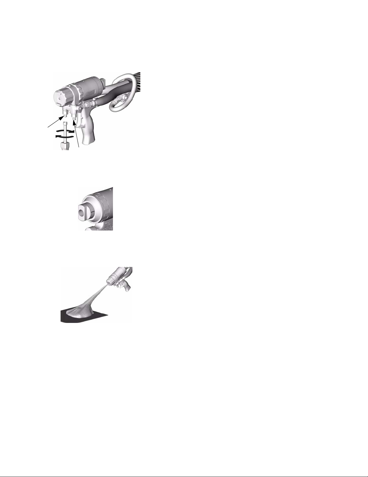
Setup
8. Open B (RESIN) fluid valve (about three half
turns). Then open A (ISO) fluid valve.
B
A
TI3838a
9. Disengage piston safety lock, page 12.
TI3849a
10. Test spray onto cardboard. Adjust pressure and
temperature to get desired results.
TI3861a
11. Apply layer of lubricant over front of gun and
lock ring, or use gun cover to prevent overspray
buildup and ease disassembly. See page 53 to
order Fusion Gun Lubricant and gun cover.
12. Gun is ready to spray.
14 309856P
Page 15
Adjust Purge Rod
Adjust Purge Rod
1. Engage piston safety lock, page 12.
2. Close fluid valves A and B.
B
A
U
TI3850a
TI3837a
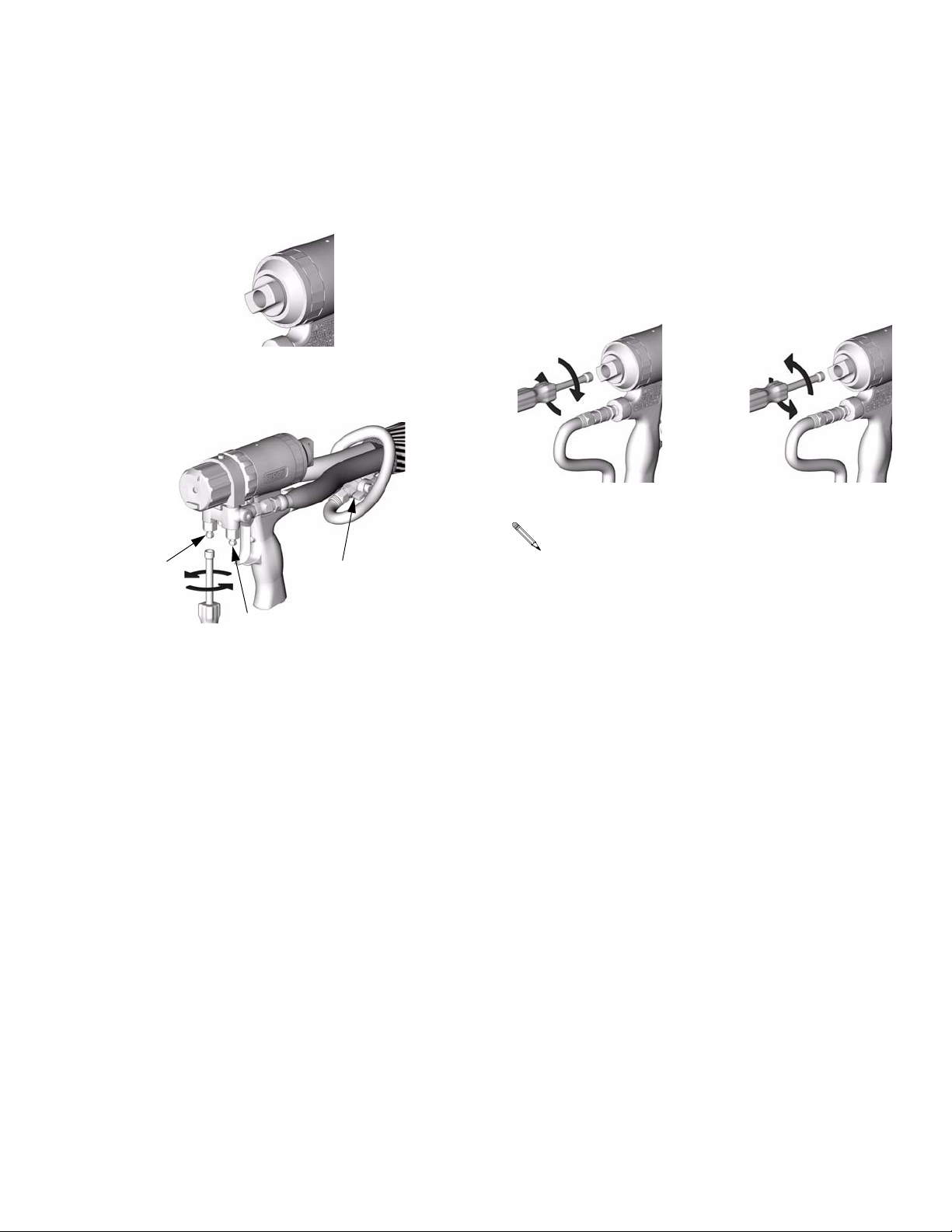
3. Connect air supply and open air valve (U).
4. Adjust purge rod with nut driver clockwise until it
just touches CeramTip, then back off 1/8-1/4 turn.
1/8-1/4 Turn
TI3829a TI3828a
Be sure to back out purge rod 1-2 turns before
changing CeramTips or mix modules. Readjust
purge rod after replacing CeramTips or mix
modules.
309856P 15
Page 16
Adjust Flat CeramTip
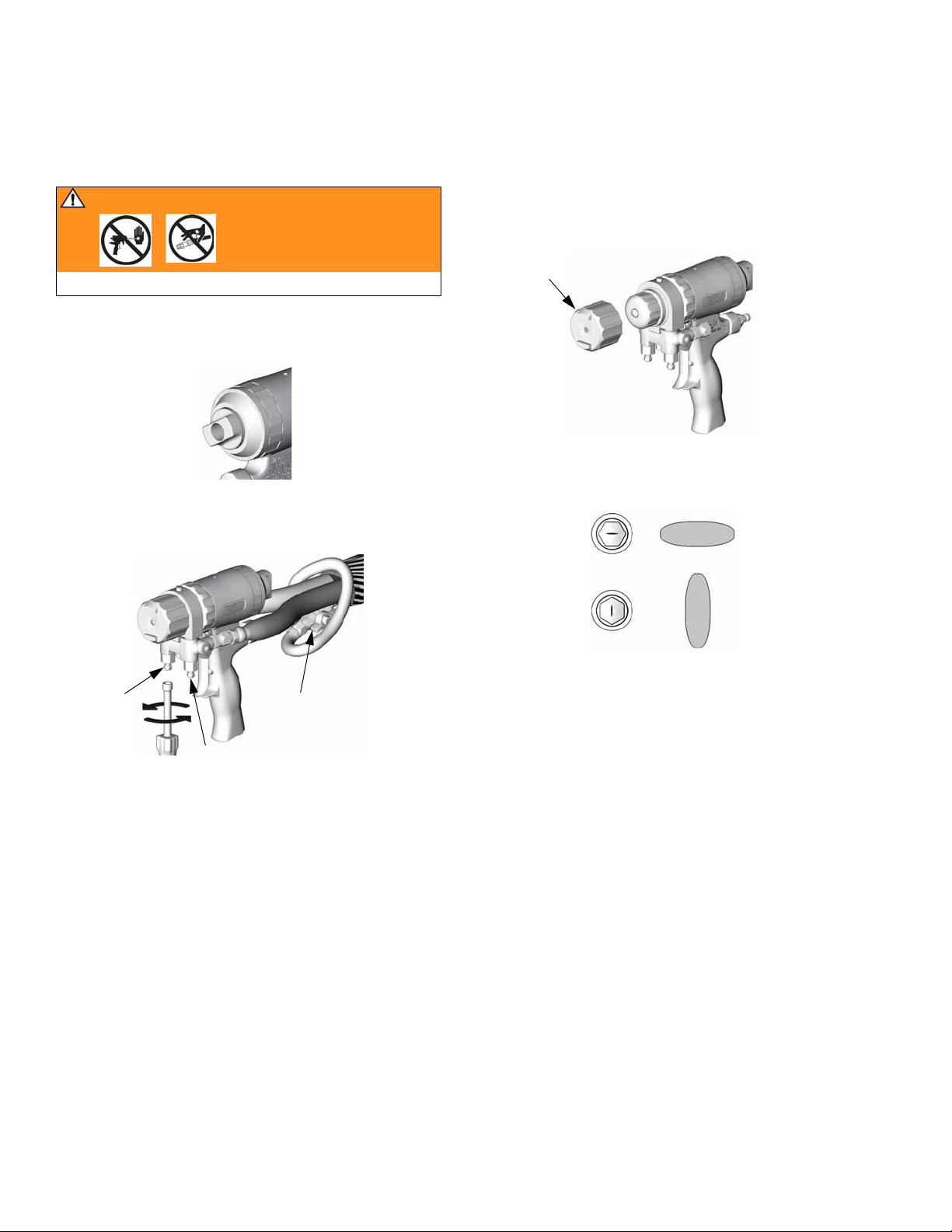
Adjust Flat CeramTip
WARNING
Read warnings, page 9.
1. Engage piston safety lock, page 12.
2. Close fluid valves A and B.
3. Remove air cap (9).
9
TI3854a
TI3850a
4. Using nut driver, position CeramTip as desired.
TI3867a
B
A
U
TI3837a
5. Reassemble air cap (9) fingertight.
16 309856P
Page 17

Shutdown
Daily Shutdown
Follow Pressure Relief Procedure, page 18.
Shutdown for More than a Day
1. Flush Gun, page 22.
2. Follow Pressure Relief Procedure, page 18.
Shutdown
309856P 17
Page 18

Pressure Relief Procedure
Pressure Relief Procedure
WARNING
Read warnings, page 9. Relieve pressure before
cleaning or repairing gun.
1. Engage piston safety lock, page 12.
TI3850a
Air supply is required for gun actuation. Do not
disconnect gun air supply until fluid pressure is
relieved.
2. Close fluid valves A and B. Leave air valve (U)
open.
4. Trigger gun onto cardboard or into waste container
to relieve pressure.
TI4243a
5. Engage piston safety lock, page 12.
TI3850a
WARNING
B
A
U
3. Disengage piston safety lock, page 12.
TI3837a
TI3849a
If fluid in the hose and proportioner is still under pressure, follow the Pressure Relief Procedure in the proportioner manual.
To relieve pressure in the hose after the gun is
removed, place the fluid manifold over containers, facing away from you. Very carefully open the fluid valves.
Under high pressure, fluid will spray sideways from the
fluid ports.
TI2484A
18 309856P
Page 19

Optional Configurations
Optional Configurations
Optional Fluid Manifold Position
Fluid manifold is mounted to bottom of gun, with A side
on left, viewed from operator’s position at back of gun. If
desired, manifold may be moved to top of gun. Doing
this will reposition A side parts (fluid inlet, check valve,
and fluid housing A side) to right.
CAUTION
To prevent cross-contamination of gun’s wetted parts,
do not interchange A component (isocyanate) and B
component (resin) parts.
1. Follow Pressure Relief Procedure, page 18.
2. Disconnect air (D) and remove fluid manifold (G).
P
F
3. Unscrew lock ring (P) until front end of gun is
loose.
4. Rotate fluid housing (F) 180° and retighten lock
ring very securely.
5. Attach fluid manifold. Connect air. Return gun to
service.
G
D
TI3837a
309856P 19
Page 20

Optional Configurations
Optional Hose Position
Fluid inlet swivels and air quick disconnect fitting point to
rear. If desired, these positions can be changed so
hoses travel downward.
Fluid Hoses
CAUTION
To prevent cross-contamination of gun’s wetted parts,
do not interchange A component (ISO) and B component (RESIN) parts.
1. Follow Pressure Relief Procedure, page 18. Also
relieve system pressure, see proportioner manual.
2. Disconnect air (D) and remove fluid manifold (G).
4. Apply thread sealant to plugs (W), elbows (V), and
male threads of swivels (A, B). Install elbows (V) in
optional inlets (N), facing down. Install swivels (A,
B) in elbows. Be sure to install A swivel (smaller) in
A side. Install plugs (W) where swivels had been.
Torque all parts to 235-245 in-lb (26.6-27.7 N•m).
W
B
N
V
A
TI2646A
5. Connect A and B hoses to A and B swivels.
Air Hose
1. Remove fitting (D) and plug (J). Reverse positions.
Apply thread sealant and torque to 125-135 in-lb
(14-15 N•m).
G
D
TI3837a
3. Disconnect fluid hoses from inlet swivels (A, B).
Remove swivels. Remove plugs from optional
inlets (N).
B
A
N
TI2417A
D
TI3853a
J
2. Attach fluid manifold. Connect air. Return gun to
service.
20 309856P
Page 21

Maintenance
Maintenance
Supplied Tool Kit
• Hex Nut Driver; 5/16
• Screwdriver; 1/8 blade
• CeramTip Drill Bit; various sizes depending on
CeramTip size. See T
• Mix Module Drill Bit; various sizes depending on
port size. See T
• 117661 Pin Vise; dual reversible chucks
Reversible
• 15B817 Flush Manifold
ABLE 2, page 26.
ABLE 1, page 24.
Reversible
TI3864a
Keep Gun Clean
4. Clean Muffler, page 22.
5. Clean Fluid Manifold, page 22.
6. Clean Slip-Fit Polycarballoy Mix Module, page
23.
Daily
Follow Shutdown, page 17.
Weekly to Monthly
1. Clean Purge Rod, page 27.
Keep gun clean with accessory gun cover, page 53.
Applying a light coat of lubricant will make cleaning easier. Lubricate threads and outside of lock ring (11) to
ease disassembly. Use Fusion Gun Lubricant, page 53.
As Needed
1. Clean Outside of Gun, page 22.
2. Clean CeramTip, page 26, a minimum of once a
day.
3. Clean Air Cap, page 22.
2. Clean Check Valves, page 41. Check o-rings and
screens.
3. Check that piston safety lock threaded connection
is tight, page 44.
309856P 21
Page 22

Maintenance
Flush Gun
If it is necessary to flush gun, use following procedure.
WARNING
Read warnings, page 10.
1. Follow Pressure Relief Procedure, page 18.
2. Flush with a compatible solvent.
3. Flush into a grounded metal pail, holding a metal
part of fluid manifold firmly to side of pail. Use the
lowest possible fluid pressure when flushing.
Clean Air Cap
Soak air cap in compatible solvent. If necessary, clean
gently with stiff brush.
Clean Muffler
A partially plugged muffler will slow gun actuation.
Remove and clean muffler with compatible solvent.
Clean Fluid Manifold
Clean fluid manifold sealing faces with compatible solvent and a brush whenever removed from gun. Be sure
to clean the two fluid ports (X) in the top mating surface.
Do not damage the flat sealing surfaces. Cover with
Fusion Lubricant (page 53) if left exposed, to seal out
moisture.
X
4. Follow Pressure Relief Procedure, page 18.
Flush Manifold 15B817 is included with gun.
Install in place of fluid manifold and connect solvent line to flush gun.
Solvent Flush Kits 248139 and 248229 are available as accessories. See page 53.
Clean Outside of Gun
Wipe off outside of gun with compatible solvent.
CAUTION
Use N Methyl Pyrrolidone (NMP), Dynasolve CU-6,
Dzolv, or equivalent to soften cured material when
cleaning the outside of gun. Do not use as flushing
solvents.
TI2411-1
22 309856P
Page 23

Clean Slip-Fit Polycarballoy Mix Module
1. Follow Pressure Relief Procedure, page 18.
2. Flush Gun, page 22.
Maintenance
TI3863a
3. Remove mix module, page 38.
CAUTION
To avoid damaging mix module, do not force drill bits
when cleaning impingement ports. Some ports are
offset or angled.
4. See FIG. 1 and FIG. 2. Clean mix module impinge-
ment ports (IP) with appropriate size drill (supplied). See T
identification chart under Drill Bit Kits, page 51.
Component B (RES) impingement ports, at rear
of mix module, are angled toward front of gun.
See F
IG. 2.
Some mix modules have counterbored holes (CB)
and require two drill sizes to clean impingement
ports completely. See F
ABLE 1, page 24. Also see
IG. 3 and TABLE 1.
FIG. 1. Cleaning Component A (ISO) Ports
F
IG. 2. Cleaning Component B (Resin) Ports
NOTE: View is not to scale.
CB
IP
TI3862a
5. Reassemble, page 38.
IP
Mix Modules
XF1313,
XF1818,
MF1818,
XF1318,
XF1824
F
IG. 3. Mix Module Cross Section
309856P 23
All Other
Mix Modules
TI3876a
Page 24

Maintenance
Table 1: Impingement Port Cleanout Drill Sizes
Standard Round Slip-Fit Polycarballoy Mix Modules
Mix Module
Part No.
MR3535 2 #73 .0240 (0.61) N/A N/A
MR4747 2 #67 .0320 (0.81) N/A N/A
MR5757 3 #67 .0320 (0.81) N/A N/A
MR6666 4 #67 .0320 (0.81) N/A N/A
MR8282 4 #60 .0400 (1.02) N/A N/A
MR9494 4 #56 .0465 (1.18) N/A N/A
No. of
Impinge-
ment Ports
Standard Flat Slip-Fit Polycarballoy Mix Modules
Impingement Port Drill Counterbore Drill
Drill Size
(nominal)
Drill Diameter
in. (mm)
Drill Size
(nominal)
Drill Diameter
in. (mm)
Mix Module
Part No.
MF1818 1 #77 .0180 (0.46) #67 .0320 (0.81)
MF2929 1 #69 .0292 (0.74) N/A N/A
MF3535 2 #73 .0240 (0.61) N/A N/A
MF4747 2 #67 .0320 (0.81) N/A N/A
MF5757 3 #67 .0320 (0.81) N/A N/A
Mix Module
Part No.
XR2323 1 #74 .0230 (0.57) N/A N/A
XR2929 1 #69 .0292 (0.74) N/A N/A
XR3535 2 #73 .0240 (0.61) N/A N/A
XR4747 2 #67 .0320 (0.81) N/A N/A
XR5757 3 #67 .0320 (0.81) N/A N/A
No. of
Impinge-
ment Ports
Direct Impingement Round Slip-Fit Polycarballoy Mix Modules
No. of
Impinge-
ment Ports
Impingement Port Drill Counterbore Drill
Drill Size
(nominal)
Impingement Port Drill Counterbore Drill
Drill Size
(nominal)
Drill Diameter
in. (mm)
Drill Diameter
in. (mm)
Drill Size
(nominal)
Drill Size
(nominal)
Drill Diameter
Drill Diameter
in. (mm)
in. (mm)
24 309856P
Page 25

Direct Impingement Flat Slip-Fit Polycarballoy Mix Modules
Mix Module
Part No.
XF1313 1 #81 .0130 (0.33) #67 .0320 (0.81)
XF1818 1 #77 .0180 (0.46) #67 .0320 (0.81)
XF2323 1 #74 .0230 (0.57) N/A N/A
XF2929 1 #69 .0292 (0.74) N/A N/A
XF3535 2 #73 .0240 (0.61) N/A N/A
XF4747 2 #67 .0320 (0.81) N/A N/A
XF5757 3 #67 .0320 (0.81) N/A N/A
XF1318 1 #81 .0130 (0.33) #67 .0320 (0.81)
XF1824 1 #77 .0180 (0.46) #67 .0320 (0.81)
XF2332 1 #74 .0230 (0.57) N/A N/A
No. of
Impinge-
ment Ports
1 #77 .0180 (0.46) #67 .0320 (0.81)
1 #74 .0230 (0.57) N/A N/A
1 #67 .0320 (0.81) N/A N/A
Impingement Port Drill Counterbore Drill
Drill Size
(nominal)
Drill Diameter
in. (mm)
Drill Size
(nominal)
Drill Diameter
in. (mm)
Maintenance
309856P 25
Page 26

Maintenance
Clean CeramTip
Round CeramTip Flat CeramTip
1. Follow Pressure Relief Procedure, page 18.
2. Remove CeramTip, page 34.
3. Clean CeramTip hole with appropriate size drill
(supplied). See T
chart under Drill Bit Kits, page 51.
Table 2: Cleanout Drill Sizes for Round CeramTips
Round CeramTip Kit
Part No.
RTM024 #73 .0240 (0.61)
RTM030 #67 .0320 (0.81)
RTM040 #60 .0400 (1.02)
RTM055 #54 .0550 (1.40)
ABLE 2. Also see identification
TI3868a
Drill Size
(nominal)
Cleanout Drill Diameter
in. (mm)
1. Follow Pressure Relief Procedure, page 18.
2. Remove CeramTip, page 34.
3. Soak CeramTip in compatible solvent. Clean gen-
tly with 15D234 Tip Cleanout Tool, page 53, to fit
tip configuration.
4. Reposition CeramTip horizontally or vertically.
TI3867a
External Quick Cleaning Method
1. Engage piston safety lock, page 12.
RTM070 #50 .0700 (1.78)
RTM080 2.0 mm .0787 (2.00)
RTM090 #43 .0890 (2.26)
RTM100 #39 .0995 (2.53)
RTM110 7/64 0.1094 (2.78)
4. Clean CeramTip internal dome with 15D234 Tip
Cleanout Tool, page 53.
TI3850a
2. Close fluid valves A and B.
TI2411A
26 309856P
Page 27

Maintenance
3. Clean CeramTip hole (E) with appropriate size drill
(supplied). See T
chart under Drill Bit Kits, page 51.
Clean flat tip slit (H) with tip cleanout tool 15D234
(page 53).
15D234
ABLE 2. Also see identification
E
TI3868a
H
4. Open B (RESIN) fluid valve (about three half
turns). Then open A (ISO) fluid valve.
Stuck Purge Rod
If purge rod (31) is stuck and cannot actuate, use this
procedure to free it.
1. Engage piston safety lock, page 12.
TI3850a
2. Trigger gun and hold. Turn purge rod counterclock-
wise.
B
A
5. Disengage piston safety lock, page 12.
TI3838a
TI3849a
TI3828a
3. Adjust Purge Rod, page 15.
Clean Purge Rod
Clean purge rod (31) weekly or monthly.
1. Follow Pressure Relief Procedure, page 18.
2. Flush Gun, page 22.
309856P 27
Page 28

Maintenance
3. Disconnect air (D) and remove fluid manifold (G).
G
D
TI3837a
4. Disassemble Front End, page 35.
5. Clean exposed portion of purge rod (31). Apply
Fusion Gun Lubricant, page 53.
Adjust Front Rod Seal
If fluid misting occurs from tip when gun is not triggered,
use following procedure to temporarily stop leakage until
parts are replaced.
1. Follow Pressure Relief Procedure, page 18.
2. Back out purge rod 1-2 turns with nut driver.
TI3828a
3. Remove air cap (9).
31
TI3873a
6. Reassemble Front End, page 36.
7. Adjust Purge Rod, page 15.
8. Attach fluid manifold. Connect air. Return gun to
service.
28
9
TI3854a
4. Trigger gun and hold. Tighten retainer (28) an addi-
tional notch, to tighten front seal (46) onto purge
rod (31).
5. Detrigger gun. Reassemble air cap (9) fingertight.
6. Adjust Purge Rod, page 15.
28 309856P
Page 29

Maintenance
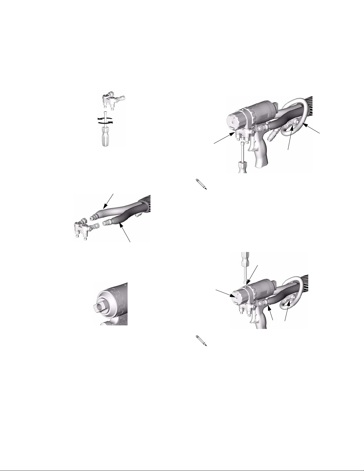
Adjust Rear Rod Seal
1. Follow Pressure Relief Procedure, page 18.
2. Flush Gun, page 22.
3. Remove fluid manifold (G). Leave air connected.
G
TI3852a
6. Remove fluid housing (7) from rod (31).
7. Reassemble Front End, page 36.
8. Adjust Purge Rod, page 15.
9. Attach fluid manifold. Return gun to service.
4. Disassemble Front End, page 35.
5. Assemble fluid housing (7) backwards onto lubri-
cated purge rod (31). Adjust rear rod seal nut (23)
with nut driver until drag is felt when sliding on rod.
7 31
23
TI3831a
309856P 29
Page 30

Troubleshooting
Troubleshooting
1. Follow Pressure Relief Procedure, page 18,
before checking or repairing gun.
2. Check all possible problems and causes before
disassembling gun.
CAUTION
To prevent cross-contamination of the gun’s wetted
parts, do not interchange A component (isocyanate)
and B component (resin) parts.
PROBLEM CAUSE SOLUTION
Gun does not fully actuate when triggered.
Fluid does not spray when gun is fully
actuated.
Gun actuates slowly or with delayed
action.
Purge rod will not actuate. No air pressure. Connect air supply.
Piston safety lock engaged. Disengage piston safety lock, page
12.
Plugged muffler (22). Clean, page 22.
Damaged air valve o-rings (24). Replace, page 44.
Closed fluid valves (12b). Open.
Plugged impingement ports. Clean, page 23.
Plugged check valves (36). Clean, page 41.
Plugged muffler (22). Clean, page 22.
Damaged piston o-rings (16, 19). Replace, page 42.
Dirty air valve, or damaged o-rings
(24).
Mix module nut (25) too tight. Loosen nut, then retighten, page 37.
Incorrect purge rod adjustment. Adjust Purge Rod, page 15.
Loose lock ring (11). Tighten, use tool if necessary. Adjust
Low air pressure. Set air pressure above 80 psi (0.56
Buildup on purge rod (31). See Clean Purge Rod, page 27.
Clean air valve or replace o-rings,
page 44.
Purge Rod, page 15.
MPa, 5.6 bar).
30 309856P
Page 31

Troubleshooting
PROBLEM CAUSE SOLUTION
Loss of round pattern. Dirty CeramTip (40). Clean, page 26.
Too little cleanoff air. Readjust, page 13.
Loss of flat pattern. Plugged CeramTip (40). Clean in compatible solvent.
Worn CeramTip (40). Replace, page 34.
Pressure imbalance. Plugged impingement ports. Clean, page 23. Reinstall mix mod-
ule, page 38.
Plugged check valves (36). Clean, page 41.
Viscosities not equal. Adjust temperature to compensate.
Fluid mist from CeramTip. Worn mix module (39). Replace, page 38.
Worn front rod seal (46). Replace, page 40.
Excessive overspray. Too much cleanoff air. Reduce, page 13.
Rapid buildup of material on air cap. Too little cleanoff air. Increase, page 13.
Fluid does not shut off when fluid
Damaged fluid valves (12b). Replace.
valves are closed.
Reduced cleanoff air. Plugged air passage. Open.
Air leakage around fluid housing. Damaged or missing o-ring (20). Replace.
Air leakage from piston safety lock. Damaged or missing o-rings (18). Replace, page 42.
Burst of air from muffler when gun is
Normal. No action required.
triggered.
Steady air leakage from muffler. Damaged air valve o-rings (24) Replace, page 44.
Damaged piston o-rings (16, 19). Replace, page 42.
Air leakage from front air valve. Damaged air valve o-rings (24). Replace, page 44.
Component B (resin) leak from fluid
Worn rear rod seal. Adjust Rear Rod Seal, page 29.
housing.
309856P 31
Page 32

Troubleshooting
Theory of Operation
Gun Triggered (Fluid Spraying)
Purge rod (31) moves back, opening impingement ports
(IP). Components A and B combine in mix module (39).
Fluid sprays from CeramTip (40).
Cleanoff air flows whether gun is triggered or detriggered. See page 13 to adjust.
KEY
Fluid
Cleanoff Air
31
IP
40
Gun Detriggered (Mechanical Purging)
Purge rod (31) moves forward, closing impingement
ports (IP) and shutting off fluid flow. Rod pushes through
mix module (39) and bottoms on CeramTip (40), forcing
out excess fluid and restoring proper orifice diameter.
Cleanoff air flows whether gun is triggered or detriggered. See page 13 to adjust.
KEY
Fluid
Cleanoff Air
31
IP
39
TI3882a
32 309856P
39
40
TI3881a
Page 33

Cutaway View
Troubleshooting
3
31
21
48
40
9
36
28 25
44
39
19
18
14
12b
20
16
24
22
309856P 33
Page 34

Repair
Repair
Tools Required
Tools needed for complete gun repair:
• adjustable wrench
• flat head screwdriver (included)
• channel-lock pliers (2 pair)
• 5/16 hex nut driver (included)
• o-ring pick
• medium-strength Loctite®
• solvent or alcohol
Lubrication
Liberally lubricate all o-rings, seals, and threads with
Fusion Gun Lubricant, page 53. Lubricate threads and
outside of lock ring (11).
Replace CeramTip
1. Follow Pressure Relief Procedure, page 18.
3. Back out purge rod 1-2 turns with nut driver.
TI3828a
4. Remove air cap (9), retainer (28), and CeramTip
(40).
4028
9
TI3843a
2. Remove fluid manifold (G). Leave air connected.
G
TI3852a
If CeramTip is stuck, trigger and detrigger gun
once to release it.
5. Install new CeramTip (40). Lubricate all threads.
Install retainer (28) fingertight, plus 1 notch. Install
air cap (9) fingertight.
6. Adjust Purge Rod, page 15.
7. Attach fluid manifold. Return gun to service.
34 309856P
Page 35

Repair
Disassemble Front End
WARNING
Read warnings, page 9. Proper attachment of front
end is critical. Do not operate gun if front end is loose
or lock ring is not snug against handle.
1. Follow Pressure Relief Procedure, page 18.
2. Flush Gun, page 22.
3. Back out purge rod 1-2 turns with nut driver.
CAUTION
If lock ring (11) is stuck due to material buildup, do not
force it by turning entire front end. Locating tabs (Z)
may break off. Soak front of gun in solvent to soften
cured material and free lock ring.
CAUTION
To prevent damage to purge rod (31), always pull front
end straight off handle (1).
6. Unscrew lock ring (11) to remove front end and mix
module. Pull front end straight off handle.
11
Z
31
TI3828a
4. Remove air cap (9), retainer (28), and CeramTip
(40).
4028
9
TI3843a
5. Remove mix module nut (25), using air cap (9)
backwards, or a wrench. Remove front seal (46).
9
TI3865b
46
309856P 35
25
TI3843a
Page 36

Repair
Reassemble Front End
1. Check that o-rings (20, 21) are in position. Liberally
lubricate o-rings, threads of lock ring (11) and handle (1), and outside of lock ring.
11
21
TI3871a
2. Orient front end as required for desired fluid mani-
fold mounting (bottom mounting shown). Align
slots (Y) to engage tabs (Z).
Y
20
CAUTION
To prevent damage to purge rod (31), always slide
front end straight onto purge rod.
3. Carefully slide front end straight onto purge rod
(31). Screw lock ring (11) onto handle (1) as far as
possible by hand. Push on front end to ensure it is
properly seated. Continue screwing lock ring onto
handle until tightened very securely. When properly assembled, lock ring is snug against handle.
1
11
7
31
TI3866a
TI3871a
4. Push mix module (39) onto rod (31) as far as pos-
sible.
31
39
Z
TI3873a
7
TI3845a
36 309856P
Page 37

Repair
CAUTION
Do not overtighten mix module nut (25). Overtightening can deform impingement holes and cause slow
gun actuation.
5. Lubricate all threads and reassemble mix module
nut (25) fingertight. Tighten additional 1/12 turn
with air cap (9) or wrench. Install front seal (46) on
rod (31).
1/12 Turn
31
25
TI3843a
9
46
6. Reinstall CeramTip (40). Lubricate all threads.
Install retainer (28) fingertight, plus 1 notch. Install
air cap (9) fingertight.
40
9
28
TI3843a
7. Adjust Purge Rod, page 15.
309856P 37
Page 38

Repair
Slip-Fit Polycarballoy Mix Module
See page 48 for available Slip-Fit Polycarballoy Mix
Module sizes.
1. Follow Pressure Relief Procedure, page 18.
2. Flush Gun, page 22.
3. Remove fluid manifold (G). Leave air connected.
G
TI3852a
6. Disengage piston safety lock, page 12. Trigger and
detrigger gun once to release mix module (39)
from fluid housing (7). Remove mix module.
Engage piston safety lock.
39
7
TI3845a
If mix module (39) does not protrude from fluid
housing (7), slightly loosen then retighten lock
ring (11), to allow gripping of edge for removal.
7. Push mix module (39) onto rod (31) as far as pos-
sible.
31
39
4. Remove air cap (9), retainer (28), and CeramTip
(40).
4028
9
TI3843a
5. Remove mix module nut (25), using air cap (9)
backwards, or a wrench. Remove front seal (46).
9
46
25
TI3843a
7
TI3845a
38 309856P
Page 39

Repair
CAUTION
Do not overtighten mix module nut (25). Overtightening can deform impingement holes and cause slow
gun actuation.
8. Lubricate all threads and reassemble mix module
nut (25) fingertight. Tighten additional 1/12 turn
with air cap (9) or wrench. Install front seal (46) on
rod (31).
1/12 Turn
31
25
TI3843a
9
46
9. Reinstall CeramTip (40). Lubricate all threads.
Install retainer (28) fingertight, plus 1 notch. Install
air cap (9) fingertight.
40
9
28
TI3843a
10. Adjust Purge Rod, page 15.
11. Attach fluid manifold. Return gun to service.
309856P 39
Page 40

Repair
Rear Rod Seal
1. Follow Pressure Relief Procedure, page 18.
2. Flush Gun, page 22.
3. Remove fluid manifold (G). Leave air connected.
G
TI3852a
7. Reassemble new rear seal (46) in rear rod seal nut
(23). Lubricate threads and install in fluid housing
(7) with nut driver.
8. Reassemble Front End, page 36.
9. Adjust Purge Rod, page 15.
10. Attach fluid manifold. Connect air. Return gun to
service.
4. Disassemble Front End, page 35.
5. Remove rear rod seal nut (23) with nut driver (53).
53
23
TI3869a
6. Push out rear seal (46) with screwdriver (54).
54
46
TI3872a
40 309856P
Page 41

Repair
Check Valves
Before disassembling, press on ball (36c) to test
check valve for proper movement and spring
action.
1. Follow Pressure Relief Procedure, page 18.
2. Flush Gun, page 22.
3. Disconnect air (D) and remove fluid manifold (G).
Clean and inspect check valve mating surfaces
and fluid ports.
G
D
TI3837a
CAUTION
To prevent cross-contamination of the check valves,
do not interchange A component and B component
parts. The A component check valve is marked with
an A.
WARNING
Read warnings, page 9. Damaged check valve o-rings
(36f, 36g) may result in external leakage. Replace
o-rings if any damage is seen.
5. Slide filter (36d) off. Clean and inspect parts. Thor-
oughly inspect o-rings (36f, 36g). If necessary,
remove screw (36b) and disassemble check valve.
B
A
36b
36e
36c
36d
36
36g
36a
36f
TI3836a
6. Reassemble check valves. Screw (36b) should be
flush (within 1/16 in. or 1.5 mm) of housing (36a)
surface. Liberally lubricate o-rings (36f, 36g) and
carefully reinstall in fluid housing.
7. Attach fluid manifold. Connect air. Return gun to
service.
4. Pry out check valves (36) at notch.
309856P 41
Page 42

Repair
Piston and Purge Rod
1. Follow Pressure Relief Procedure, page 18.
2. Flush Gun, page 22.
3. Disconnect air (D) and remove fluid manifold (G).
G
D
TI3837a
6. Pull purge rod to remove piston (32). Inspect pis-
ton o-ring (16) and shaft o-ring (19).
32
19
16
TI3846a
7. Inspect purge rod (31) for scratches or damage.
Unscrew rod from piston with nut driver. Inspect
o-ring (18). Liberally lubricate with Fusion Gun
Lubricant, page 53. To reassemble, thread purge
rod (31) into piston (32) just until o-ring (18) is not
visible.
32
31
18
4. Disassemble Front End, page 35.
5. Unscrew purge rod stop (15) to remove piston
safety lock assembly. Inspect o-rings (14, 18) in
place.
15
18
14
TI3847a
19
16
TI3848a
8. Liberally lubricate piston o-rings. Reinstall piston.
Shaft is keyed for proper assembly. Push firmly to
seat piston. Rotate piston/purge rod assembly
clockwise with nut driver until piston is fully seated.
TI3846a
42 309856P
Page 43

9. Install piston safety lock assembly until bottomed
out.
TI3847a
10. Reassemble Front End, page 36.
11. Adjust Purge Rod, page 15.
Repair
12. Attach fluid manifold. Connect air. Return gun to
service.
309856P 43
Page 44

Repair
Piston Safety Lock Air Valve
1. Follow Pressure Relief Procedure, page 18.
2. Flush Gun, page 22.
3. Disconnect air (D) and remove fluid manifold (G).
G
D
TI3837a
4. Unscrew cap (10) from stop (15), using two pair of
channel-lock pliers. Inspect spring (17), safety
actuator (3), bushing (4), and o-rings (14, 18).
1. Follow Pressure Relief Procedure, page 18.
2. Flush Gun, page 22.
3. Disconnect air (D) and remove fluid manifold (G).
G
D
TI3837a
4. Unscrew air valve plug (2) and remove spring (26).
Using small screwdriver (54), push spool (27) out
from front. Inspect o-rings (24).
15
18
14
17
10
3, 4
TI3835b
5. Lubricate o-rings (14, 18) and piston safety lock
actuator (3), and reassemble. Use Fusion Gun
Lubricant, page 53. Clean threads with solvent or
alcohol. Apply medium-strength Loctite® or equivalent to threads on stop (15) and cap (10), and
reassemble.
6. Attach fluid manifold. Connect air. Return gun to
service.
2
26
27
24
TI3834a
5. Liberally lubricate o-rings and reassemble. Use
Fusion Gun Lubricant, page 53. Torque plug (2) to
125-135 in-lb (14-15 N•m).
6. Attach fluid manifold. Connect air. Return gun to
service.
44 309856P
Page 45

Notes
Notes
309856P 45
Page 46

Parts
Parts
928
46*
40
†‡ 25 39
16* 8 31
★ 15★
14*
10★ 17★
4★60★
59★ 3★
‡44
‡*24
◆†‡7
†‡36b
‡*36g
†‡36a
†‡*36f
‡36e
‡36d
‡36
†12a
20
19
21*‡◆
32
46*†‡
2
36c
12e
Supplied Tools
18★
53
18
‡◆
11‡◆
23‡
35
1
34
54
TI3870a
56
5
22
4
‡
13
1
12f
6
2
29
1
1
30
48
1
49
51
Flush Manifold Detail
29 (Ref)
1
52
30 (Ref)
12d (Ref)
TI2647a
1
12b
3
12c
12d
50
1
24
27 26 2
†‡
1
4-Hose Fluid Manifold Detail
12g
1
Torque to 125-135 in-lb (14-15 N•m).
2
Torque to 20-30 in-lb (2.3-3.4 N•m).
3
Torque to 32-40 ft-lb (43-54 N•m).
4
Torque to 35-45 in-lb (4-5 N•m).
50
12e
1
12d
46 309856P
12a
TI3851c
12b
12g
12e
3
1
12f
50
12f
TI7134A
1
1
Page 47

Parts
Ref.
No. Part No. Description Qty
1 248002 HANDLE 1
2 15B208 PLUG, air valve 1
3
★ 15C374 ACTUATOR; safety 1
4
★ 15C390 BUSHING, safety 1
5 203953 SCREW; 10-24 x 3/8 in. (10 mm) 1
6 192272 PIN 1
7
†‡◆ HOUSING, fluid 1
8 118145 SPRING, purge rod 1
9 15C375 AIR CAP 1
10
★ 15C373 CAP, rear 1
11‡◆
12 246012 MANIFOLD, fluid, 2-hose;
15B215 RING, lock 1
1
includes 12a-12g
249523 MANIFOLD, fluid, 4-hose;
1
includes 12a, 12b, 12d-12g, 50
12a
† .MANIFOLD 1
12b 246356 . VALVE, fluid 2
12c 100139 . PLUG, pipe; 1/8-27 npt 2
12d 15B221 . BOLT; 5/16-24 1
12e 117634 . SWIVEL, B side; 1/8 npt(m) x
1
no. 6 JIC(f); for 2-hose manifold
117634 . SWIVEL, B side; 1/8 npt(m) x
2
no. 6 JIC(f); for 4-hose manifold
12f 117635 . SWIVEL, A side; 1/8 npt(m) x
1
no. 5 JIC(f); for 2-hose manifold
117635 . SWIVEL, A side; 1/8 npt(m) x
2
no. 5 JIC(f); for 4-hose manifold
12g 15B993 . SPRING, ring, lock 1
13 15B209 TRIGGER 1
14*
★ 248136 O-RING, rod stop; package of 6 1
15
★ 15C372 STOP, purge rod 1
16* 248135 O-RING, piston; package of 6 1
17
★ 118144 SPRING, piston safety lock 1
18
★ 248095 O-RING, purge rod; package of 6 1
19 248096 O-RING, piston shaft;
1
package of 6
20 248138 O-RING, housing, small;
1
package of 6
21
‡◆* 248132 O-RING, housing, large;
1
package of 6
22 119626 MUFFLER 1
23
‡ 15C378 NUT, rod seal, rear 1
‡* 246354 O-RING; package of 6 1
24
25 15C377 NUT, mix module 1
26 117485 SPRING, air valve 1
27 15B202 SPOOL, air valve 1
28 15C376 RETAINER, CeramTip 1
29 100721 PLUG, pipe; 1/4-18 npt 1
30 117509 QUICK-DISCONNECT, male, air;
1
1/4 npt(m)
31 248001 ROD, purge; includes 1 of item 18 1
32 15C371 PISTON 1
34 117661 VISE, pin; dual reversible chucks 1
35
‡◆ 116550 RING, retaining 1
Ref.
No. Part No. Description Qty
36
‡ 246731 VALVE, check, A side; includes
1
36a-36g
246352 VALVE, check, B side; includes
1
36a-36g
36a
‡† .HOUSING 1
36b
‡† 15B214 . SCREW; 5/16-18 x
1
1/2 in. (13 mm)
36c
‡ 104396 . BALL; carbide 1
36d
‡ . SCREEN; see page 52 1
36e‡ 117490 . SPRING 1
36f
‡* 248133 . O-RING, check valve face;
1
package of 6
36g
‡* 248129 . O-RING, check valve housing;
1
package of 6
37▲ 222385 TAG, warning; not shown 1
39 MODULE, mix, round, standard;
1
see page 48
MODULE, mix, flat, standard; see
1
page 48
MODULE, mix, round, direct
1
impingement; see page 49
MODULE, mix, flat, direct impinge-
1
ment; see page 49
40 CeramTip; see page 50 1
44‡
46
15C382 VALVE, cleanoff air 1
†‡* 248003 SEAL KIT, purge rod; includes 4
1
seals
48 117510 COUPLER, air line 1
49 15B772 HOSE, air; 1/4 npsm (fbe); 18 in.
1
(0.46 m)
50 112307 ELBOW, street;1/8 npt (m x f) 2
51 15B565 VALVE, ball; 1/4 npt (m x f) 1
52 15B817 MANIFOLD, gun flush 1
53 117642 NUT DRIVER, hex; 5/16 1
54 118575 SCREWDRIVER; 1/8 blade 1
55 197979 COVER, gun; not shown 1
56 15C480 WASHER, wave 1
57■ 118665 LUBRICANT, Fusion Gun; 4 oz
1
(113 gram)
58▲ 15D235 SIGN, instruction 1
59
★ 15D329 STOP, rod 1
60
★ 115452 RING, retaining 1
* These parts are only available in repair kits. To select
a kit, refer to Gun Repair Kits on page 52.
† These parts are not available singly.
‡ These parts are included in Front End Replacement
Kit 246875 (includes 1 of items 24 and 46).
★ These parts are included in Safety Stop Assembly
248028 (includes 1 of item 18).
▲ Replacement Danger and Warning labels, tags, and
cards are available at no cost.
■ Available in 248279 Kit, package of 10. See page 53.
◆ Available in Fluid Housing Assembly Kit 248004.
309856P 47
Page 48

Parts
Slip-Fit Polycarballoy Mix Module Kits
Slip-Fit Polycarballoy Mix Module Part Numbering Code
Example
First Two Digits Second Two Digits Last Two Digits
Part No.
MR3535 MR=Mechanical purge standard, round pattern 35=Component A
MF3535 MF=Mechanical purge standard, flat pattern
impingement port
size (.035 in.).***
35=Component B
impingement port
size (.035 in.).***
XR3535 XR=Mechanical purge direct impingement, round pattern
XF3535 XF=Mechanical purge direct impingement, flat pattern
*** Some modules have multiple impingement ports (see below). Size is given as the equivalence of a single port.
Standard Round Pattern Guns
Slip-Fit Polycarballoy
Mix Module Kit
(includes drill bits)
MR3535 2 #73
MR4747 2 #67
MR5757 3 #67
MR6666 4 #67
MR8282 4 #60
No. of
Impingement
Ports
Impingement
Port Drill Bit
Size, nominal**
MR9494 4 #56
Standard Flat Pattern Guns
Slip-Fit Polycarballoy
Mix Module Kit
(includes drill bits)
MF1818 1 #77 #67
MF2929 1 #69 N/A
MF3535 2 #73 N/A
MF4747 2 #67 N/A
MF5757 3 #67 N/A
**For further information, see identification chart under Drill Bit Kits, page 51.
No. of
Impingement
Ports
Impingement
Port Drill Bit
Size, nominal**
Counterbore
Drill Bit Size,
nominal**
48 309856P
Page 49

Direct Impingement Round Pattern Guns
Parts
Slip-Fit Polycarballoy
Mix Module Kit
(includes drill bits)
XR2323 1 #74
XR2929 1 #69
XR3535 2 #73
XR4747 2 #67
XR5757 3 #67
No. of
Impingement
Ports
Impingement
Port Drill Bit
Size, nominal**
Direct Impingement Flat Pattern Guns
Slip-Fit Polycarballoy
Mix Module Kit
(includes drill bits)
XF1313 1 #81 #67
XF1818 1 #77 #67
XF2323 1 #74 N/A
XF2929 1 #69 N/A
XF3535 2 #73 N/A
No. of
Impingement
Ports
Impingement
Port Drill Bit
Size, nominal**
Counterbore
Drill Bit Size,
nominal**
XF4747 2 #67 N/A
XF5757 3 #67 N/A
XF1318 1 #81 #67
1 #77
XF1824 1 #77 N/A
1 #74
XF2332 1 #74 N/A
1 #67
**For further information, see identification chart under Drill Bit Kits, page 51.
309856P 49
Page 50

Parts
CeramTip Kits
Round CeramTip Part Numbering Code
Example
Part No.
RTM055 RTM=Round CeramTip mechanical purge Equivalent orifice diameter size (.055 in.)
First Three Digits Last Three Digits
Round CeramTips (include drill bit)
CeramTip Part No. Drill Bit Size, nominal**
RTM024 #73
RTM030 #67
RTM040 #60
RTM055 #54
RTM070 #50
RTM080 2.0 mm
RTM090 #43
RTM100 #39
RTM110 7/64
**For further information, see identification chart under Drill Bit Kits, page 51.
Flat CeramTip Part Numbering Code
Example
Part No.
FTM848 FTM=Flat CeramTip mechanical purge 8x2=pattern length
First Three Digits Fourth Digit Last Two Digits
(8x2=16 in.)
Flat CeramTips
CeramTip Part No. Pattern Size, in. (mm)
FTM317 very low flow, 6-8 (152-203)
FTM424 low flow, 8-10 (203-254)
FTM438 medium flow, 8-10 (203-254)
FTM624 low flow, 12-14 (305-356)
FTM638 medium flow, 12-14 (305-356)
FTM838 medium flow, 16-18 (406-457)
FTM848 high flow, 16-18 (406-457)
Equivalent orifice diameter size
(.048 in.)
50 309856P
Page 51

Drill Bit Kits
For cleaning gun ports and orifices. Illustrations are actual size, for comparison.
Not all sizes are used with your gun.
Parts
Kit Part No. Qty in Kit
Drill Bit Size
nominal in. mm
246623 3 #32 0.116 2.90
246810 3 7/64 0.109 2.77
246813 3 #39 .099 2.51
246624 3 3/32 .094 2.39
246812 3 #43 .089 2.26
246625 3 #44 .086 2.18
246811 3 2 mm .079 2.00
246626 6 #50 .070 1.78
248893 6 1/16 .062 1.59
246627 6 #53 .060 1.52
246809 6 #54 .055 1.40
246628 6 #55 .052 1.32
246814 6 #56 .046 1.18
246629 6 #58 .042 1.07
246808 6 #60 .040 1.02
248618 6 #63 .037 0.94
Illustration
248891 6 #66 .033 0.84
246807 6 #67 .032 0.81
246630 6 #69 .029 0.74
248892 6 #70 .028 0.71
246815 6 #73 .024 0.61
276984 6 #74 .023 0.57
246631 6 #76 .020 0.51
246816 6 #77 .018 0.46
246817 6 #81 .013 0.33
309856P 51
Page 52

Parts
Gun Repair Kits
Read the chart left to right and top to bottom to find the quantity of each part in the kits.
Ref.
No.
14 248136 (6) 1
16 248135 (6) 1
18 248095 (6) 2
19 248096 (6) 1
20 248138 (6) 1
21 248132 (6) 1
24 246354 (6) 4
36f 248133 (6) 2
36g 248129 (6) 2
46 248003 (4)
Bulk O-ring
Kits, (qty)
246351
Check Valve
O-ring Kit
248000
Complete
O-ring Kit
Check Valve Filter Screen Kits (10 per kit)
80 mesh filter screen is standard with gun.
246357 40 mesh (.015 in., 375 micron)
246358 60 mesh (.010 in., 238 micron)
246359 80 mesh (.007 in., 175 micron)
52 309856P
Page 53

Accessories
Accessories
Gun Cover
244915
Keeps gun clean while spraying. Pack of 10.
Fusion Gun Lubricant Kit
248279 Pack of 10 Tubes, 4 oz (113 gram)
High adhesion, water resistant, lithium-based lubricant
for rebuilding Fusion Gun. MSDS sheet MSD025 available at www.graco.com.
Tip Cleanout Tool
15D234
Designed to fit CeramTip internal dome and flat tip slits.
End for
Mechanical
End for Air
Purge Tips
Purge Tips
TI4244a
Circulation Manifold
246362
Attach to gun fluid manifold to enable preheating of
hose. See manual 309818.
TI3877a
Flushing Manifold
15B817 Manifold Block
See ref. no. 52, page 47.
Solvent Flush Kits
248139 1 qt (0.95 liter) Solvent Cup
Portable, for remote solvent flush. Includes 15B817
Flushing Manifold. See manual 309963.
Gun Cleaning Kit
15C161
Ultimate Gun Cleaning Kit.
309856P 53
TI4165a
Page 54

Accessories
Solvent Flush Pail Kit
248229 5.0 gal. (19 liter) Pail
Includes flush manifold with individual A and B shutoff
valves, and air regulator. See manual 309963.
TI4211b
Hose Adapter Kits
246944
To connect non-Graco gun to Graco heated hose.
248029
To connect Graco Fusion gun to non-Graco D-gun hose
set.
246945
To connect Graco Fusion gun to non-Graco heated
hose.
Pour Nozzle Kit
248682
To convert mechanical purge gun for pour applications.
Includes nozzle, retainer, and tip.
54 309856P
Page 55

Technical Data
Category Data
Maximum Fluid Working Pressure 3500 psi (24.2 MPa, 242 bar)
Minimum Air Inlet Pressure 80 psi (0.55 MPa, 5.5 bar)
Maximum Air Inlet Pressure 130 psi (0.9 MPa, 9 bar)
Maximum Fluid Temperature 200° F (94° C)
Air Inlet Size 1/4 npt Quick Disconnect Nipple
A Component (ISO) Inlet Size -5 JIC; 1/2-20 UNF
B Component (Resin) Inlet Size -6 JIC; 9/16-18 UNF
Typical Flow Rate See charts pages 4-7.
Sound Pressure 70 dB(A), at 100 psi (0.7 MPa, 7 bar)
Sound Power, measured per ISO
9416-2
Length 7.6 in. (193 mm)
Height 8.1 in. (206 mm)
Width 3.1 in. (79 mm)
Weight 2.9 lb (1.32 kg)
Wetted Parts
79.9 dB(A), at 100 psi (0.7 MPa, 7 bar)
Aluminum, stainless steel, carbon steel, chemically resistant o-rings,
ultra-high molecular weight polyethylene (UHMWPE), Polycarballoy™,
CeramTip™
Technical Data
All other brand names or marks are used for identification purposes and are trademarks of their respective owners.
309856P 55
Page 56

Graco Standard Warranty
Graco warrants all equipment referenced in this document which is manufactured by Graco and bearing its name to be free from defects in
material and workmanship on the date of sale to the original purchaser for use. With the exception of any special, extended, or limited warranty
published by Graco, Graco will, for a period of twelve months from the date of sale, repair or replace any part of the equipment determined by
Graco to be defective. This warranty applies only when the equipment is installed, operated and maintained in accordance with Graco’s written
recommendations.
This warranty does not cover, and Graco shall not be liable for general wear and tear, or any malfunction, damage or wear caused by faulty
installation, misapplication, abrasion, corrosion, inadequate or improper maintenance, negligence, accident, tampering, or substitution of
non-Graco component parts. Nor shall Graco be liable for malfunction, damage or wear caused by the incompatibility of Graco equipment with
structures, accessories, equipment or materials not supplied by Graco, or the improper design, manufacture, installation, operation or
maintenance of structures, accessories, equipment or materials not supplied by Graco.
This warranty is conditioned upon the prepaid return of the equipment claimed to be defective to an authorized Graco distributor for verification of
the claimed defect. If the claimed defect is verified, Graco will repair or replace free of charge any defective parts. The equipment will be returned
to the original purchaser transportation prepaid. If inspection of the equipment does not disclose any defect in material or workmanship, repairs will
be made at a reasonable charge, which charges may include the costs of parts, labor, and transportation.
THIS WARRANTY IS EXCLUSIVE, AND IS IN LIEU OF ANY OTHER WARRANTIES, EXPRESS OR IMPLIED, INCLUDING BUT NOT LIMITED
TO WARRANTY OF MERCHANTABILITY OR WARRANTY OF FITNESS FOR A PARTICULAR PURPOSE.
Graco’s sole obligation and buyer’s sole remedy for any breach of warranty shall be as set forth above. The buyer agrees that no other remedy
(including, but not limited to, incidental or consequential damages for lost profits, lost sales, injury to person or property, or any other incidental or
consequential loss) shall be available. Any action for breach of warranty must be brought within two (2) years of the date of sale.
GRACO MAKES NO WARRANTY, AND DISCLAIMS ALL IMPLIED WARRANTIES OF MERCHANTABILITY AND FITNESS FOR A
PARTICULAR PURPOSE, IN CONNECTION WITH ACCESSORIES, EQUIPMENT, MATERIALS OR COMPONENTS SOLD BUT NOT
MANUFACTURED BY GRACO. These items sold, but not manufactured by Graco (such as electric motors, switches, hose, etc.), are subject to
the warranty, if any, of their manufacturer. Graco will provide purchaser with reasonable assistance in making any claim for breach of these
warranties.
In no event will Graco be liable for indirect, incidental, special or consequential damages resulting from Graco supplying equipment hereunder, or
the furnishing, performance, or use of any products or other goods sold hereto, whether due to a breach of contract, breach of warranty, the
negligence of Graco, or otherwise.
FOR GRACO CANADA CUSTOMERS
The Parties acknowledge that they have required that the present document, as well as all documents, notices and legal proceedings entered into,
given or instituted pursuant hereto or relating directly or indirectly hereto, be drawn up in English. Les parties reconnaissent avoir convenu que la
rédaction du présente document sera en Anglais, ainsi que tous documents, avis et procédures judiciaires exécutés, donnés ou intentés, à la suite
de ou en rapport, directement ou indirectement, avec les procédures concernées.
Graco Information
For the latest information about Graco products, visit www.graco.com.
TO PLACE AN ORDER, contact your Graco distributor, or call this number to identify the distributor closest to you:
1-800-328-0211 Toll Free
612-623-6921
612-378-3505 Fax
All written and visual data contained in this document reflects the latest product information available at the time of publication.
Graco reserves the right to make changes at any time without notice.
This manual contains English. MM 309856
Graco Headquarters: Minneapolis
International Offices: Belgium, China, Japan, Korea
GRACO INC. P.O. BOX 1441 MINNEAPOLIS, MN 55440-1441
Copyright 2004, Graco Inc. is registered to ISO 9001
www.graco.com
Revised 06/2009
 Loading...