

Page 1
Instructions-Parts
Pneumatic
Pneumatic Pneumatic
User
Interface
User User
Interface Interface
For
professional
For For
professional professional
19Y486
19Y486 19Y486
The19Y486PumpControlModuleuses
the25B475AdvancedDisplayControl
Module(ADCM).Seemanual332013
(supplied)forcompletewarningsand
approvalsforthe25B475ADCM.
—
Pneumatic
— —
Pneumatic Pneumatic
Important
Important Important
Readallwarningsandinstructionsinthismanual,thesupplied
ADCMmanual,andtheIPKmanualsbeforeusingtheequipment.
Save
these
Save Save
these these
Pump
Pump Pump
for
controlling
for for
controlling controlling
use
only.
use use
only. only.
Pump
Pump Pump
Safety
Safety Safety
Instructions
Instructions Instructions
instructions.
instructions. instructions.
Control
Control Control
Module
Module Module
3A7709B
EN
and
monitoring
and and
monitoring monitoring
Control
Control Control
Module
Module Module
Graco
Graco Graco
Intelligent
Intelligent Intelligent
Paint
Kitchen
Paint Paint
Kitchen Kitchen
(IPK)
Pneumatic
(IPK) (IPK)
Pneumatic Pneumatic
Pumps.
Pumps. Pumps.
PROVENQUALITY.LEADINGTECHNOLOGY.
Page 2

Contents
Contents Contents
RelatedManuals................................................2
Warnings...........................................................3
PumpControlModule.........................................7
Installation..........................................................7
HazardousLocations....................................7
Grounding...................................................9
CableConnection........................................11
TypicalInstallation.......................................13
Operation...........................................................14
PressureReliefProcedure............................14
ModesofOperation......................................14
Display........................................................15
ModuleScreens...........................................16
ModuleMenuBar.........................................16
ModuleKeys................................................16
RunScreens......................................................17
PumpControlChapter..................................17
TotalizerChapter.........................................19
AgitatorChapter...........................................20
EventLogChapter.......................................21
SetupScreens....................................................22
ProleChapter.............................................22
PressureTransducerChapter.......................27
PumpSetupChapter....................................29
DiagnosticChapter......................................30
TotalizerChapter.........................................30
ModbusChapter..........................................31
MiscellaneousChapter.................................32
ErrorCodeTroubleshooting................................35
Parts..................................................................38
25B234PneumaticADCMDisplay
EnclosureAssembly.......................39
AccessoriesandKits...........................................41
AutomaticAirControlKit19Y482..................41
NXTAirControlKit19Y996..........................42
TransducerI/PKit24V001............................43
PressureTransducerKitfor4-ballPumps
24R050PressureTransducerKit
for2-ballPumps24Y245.................43
PressureTransducerKitforSanitary
Pumps24X089...............................44
CaliforniaProposition65.....................................44
Notes................................................................45
AppendixA-ModbusVariableMap.....................45
AppendixB-ControlModuleProgramming...........58
GracoStandardWarranty....................................60
Related
Related Related
Manual
Manual Manual
332013
332196
3A1244
3A3382High-Flo
3A3452
333015Endura-Flo™3D150,3D350,4D150,and4D350DiaphragmPump,Instructions
307843
No.
No. No.
Manuals
Manuals Manuals
Description
Description Description
AdvancedDisplayControlModule(ADCM),Instructions-Parts
ISPowerSupplyModules,Instructions-Parts
GracoControlArchitectureModuleProgramming,Instructions
®
4–BallPumps,Instructions-Parts
4–BallLowerswithOpenWetCup,Repair-Parts
Air-PoweredGlutton
®
Pumps,Instructions-Installation
2
3A7709B
Page 3
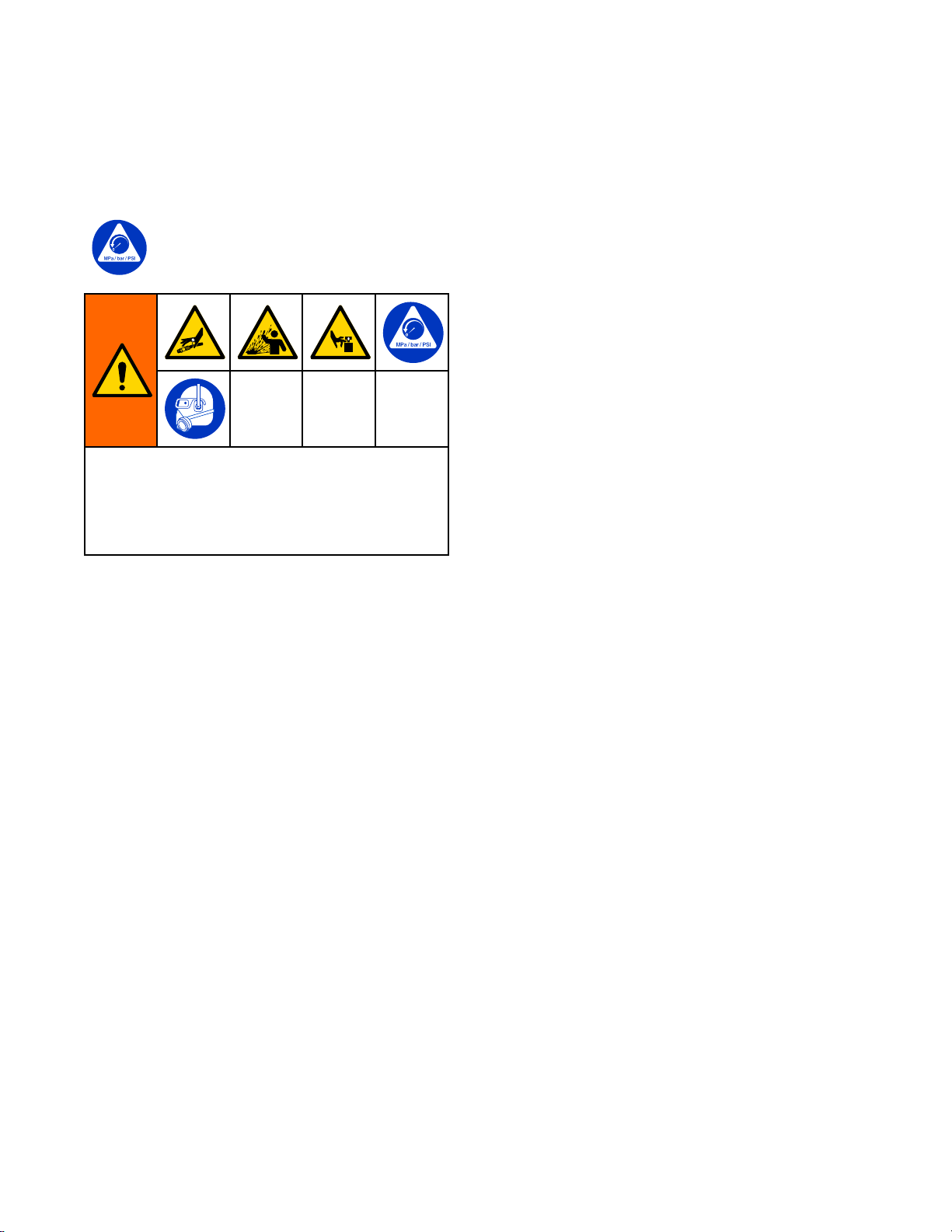
Warnings
Warnings Warnings
Thefollowingwarningsareforthesetup,use,grounding,maintenanceandrepairofthisequipment.The
exclamationpointsymbolalertsyoutoageneralwarningandthehazardsymbolreferstoprocedure-specic
risks.Whenthesesymbolsappearinthebodyofthismanualoronwarninglabels,referbacktothese
Warnings.Product-specichazardsymbolsandwarningsnotcoveredinthissectionmayappearthroughout
thebodyofthismanualwhereapplicable.
WARNING
WARNING WARNING
FIRE
AND
FIRE FIRE
Flammablefumes,suchassolventandpaintfumes,inwork work
orsolventowingthroughtheequipmentcancausestaticsparking.Tohelppreventreand
explosion:
•Useequipmentonlyinwellventilatedarea.
•Eliminateallignitionsources;suchaspilotlights,cigarettes,portableelectriclamps,and
plasticdropcloths(potentialstaticarc).
•Keepworkareafreeofdebris,includingsolvent,ragsandgasoline.
•Donotplugorunplugpowercords,orturnpowerorlightswitchesonoroffwhenammable
fumesarepresent.
•Groundallequipmentintheworkarea.SeeGrounding Grounding
•Useonlygroundedhoses.
Stop
•Stop Stop
equipmentuntilyouidentifyandcorrecttheproblem.
•Keepaworkingreextinguisherintheworkarea.
EXPLOSION
AND AND
EXPLOSION EXPLOSION
operation
operation operation
immediately
immediately immediately
HAZARD
HAZARD HAZARD
work
area
area area
canigniteorexplode.Paint
Grounding
ifstaticsparkingoccursoryoufeelashock.Donotuse
instructions.
Warnings
Staticchargemaybuilduponplasticpartsduringcleaningandcoulddischargeandignite
ammablevapors.Topreventreandexplosion:
•Cleanplasticpartsonlyinawell-ventilatedarea.
•Donotcleanwithadrycloth.
3A7709B3
Page 4
Warnings
WARNING
WARNING WARNING
INTRINSIC
INTRINSIC INTRINSIC
Intrinsicallysafeequipmentthatisinstalledimproperlyorconnectedtonon-intrinsicallysafe
equipmentwillcreateahazardousconditionandcancausere,explosion,orelectricshock.
Followlocalregulationsandthefollowingsafetyrequirements.
•InstallationshouldbeinaccordancewithANSI/ISARP12.06.01“InstallationofIntrinsically
SafeSystemsforHazardous(Classied)Locations”andtheNationalElectricalCode®
(ANSI/NFPA70).
•InstallationinCanadashouldbeinaccordancewiththeCanadianElectricalCode,CSA
C22.1,Part1,AppendixF.
•ForATEX,installperEN60079–14andapplicablelocalandnationalcodes.
•Equipmentthatcomesincontactwithintrinsicallysafeterminalsmustmeettheentity
parameterrequirementsspeciedinControlDrawing16M169.SeeAppendixAinManual
332013.Thisincludessafetybarriers,DCvoltagemeters,ohmmeters,cables,and
connections.Removetheunitfromthehazardousareawhenservicing.
•Withoutthesafetybarrier,theequipmentisnolongerintrinsicallysafeandmustnotbe
operatedinhazardouslocations,asdenedinarticle500oftheNationalElectricalCode
(USA)oryourlocalelectricalcode.
•Donotinstallequipmentapprovedonlyfornon-hazardouslocationinahazardousarea.See
theIDlabelfortheintrinsicsafetyratingforyourmodel.
•Donotuseintrinsicallysafeequipmentwithapowersupplythathasnobarrier.Intrinsic
safetymaybecompromised.
•Groundthepowersupply.Avoltagelimitingsafetybarriermustbeproperlygroundedtobe
effective.Forpropergrounding,usea12gaugeminimumgroundwire.Thebarrier’sground
mustbewithin1ohmoftrueearthground.
•Donotremoveanycoveruntilpowerhasbeenremoved.
•Donotsubstitutesystemcomponentsasthismayimpairintrinsicsafety.
SAFETY
SAFETY SAFETY
4
3A7709B
Page 5
WARNING
WARNING WARNING
SKIN
INJECTION
SKIN SKIN
INJECTION INJECTION
High-pressureuidfromgun,hoseleaks,orrupturedcomponentswillpierceskin.Thismay
looklikejustacut,butitisaseriousinjurythatcanresultinamputation.Get Get
treatment.
treatment. treatment.
•Donotspraywithouttipguardandtriggerguardinstalled.
•Engagetriggerlockwhennotspraying.
•Donotpointgunatanyoneoratanypartofthebody.
•Donotputyourhandoverthespraytip.
•Donotstopordeectleakswithyourhand,body,glove,orrag.
•FollowthePressure Pressure
orservicingequipment.
•Tightenalluidconnectionsbeforeoperatingtheequipment.
•Checkhosesandcouplingsdaily.Replacewornordamagedpartsimmediately.
HAZARD
HAZARD HAZARD
Get
immediate
immediate immediate
Pressure
Relief
Procedure
Relief Relief
Procedure Procedure
whenyoustopsprayingandbeforecleaning,checking,
Warnings
surgical
surgical surgical
EQUIPMENT
EQUIPMENT EQUIPMENT
Misusecancausedeathorseriousinjury.
•Donotoperatetheunitwhenfatiguedorundertheinuenceofdrugsoralcohol.
•Donotexceedthemaximumworkingpressureortemperatureratingofthelowestrated
systemcomponent.SeeTechnical Technical
•Useuidsandsolventsthatarecompatiblewithequipmentwettedparts.SeeTechnical Technical
Specications
Specications Specications
Forcompleteinformationaboutyourmaterial,requestSafetyDataSheets(SDSs)from
distributororretailer.
•Donotleavetheworkareawhileequipmentisenergizedorunderpressure.
•TurnoffallequipmentandfollowthePressure Pressure
•Checkequipmentdaily.Repairorreplacewornordamagedpartsimmediatelywithgenuine
manufacturer’sreplacementpartsonly.
•Donotalterormodifyequipment.Alterationsormodicationsmayvoidagencyapprovals
andcreatesafetyhazards.
•Makesureallequipmentisratedandapprovedfortheenvironmentinwhichyouareusingit.
•Useequipmentonlyforitsintendedpurpose.Callyourdistributorforinformation.
•Routehosesandcablesawayfromtrafcareas,sharpedges,movingparts,andhotsurfaces.
•Donotkinkoroverbendhosesorusehosestopullequipment.
•Keepchildrenandanimalsawayfromworkarea.
•Complywithallapplicablesafetyregulations.
MISUSE
MISUSE MISUSE
HAZARD
HAZARD HAZARD
Technical
inallequipmentmanuals.Readuidandsolventmanufacturer’swarnings.
Specications
Specications Specications
Pressure
Relief
Relief Relief
inallequipmentmanuals.
Procedure
Procedure Procedure
Technical
whenequipmentisnotinuse.
3A7709B5
Page 6
Warnings
WARNING
WARNING WARNING
PERSONAL
PERSONAL PERSONAL
Wearappropriateprotectiveequipmentwhenintheworkareatohelppreventseriousinjury,
includingeyeinjury,hearingloss,inhalationoftoxicfumes,andburns.Protectiveequipment
includesbutisnotlimitedto:
•Protectiveeyewear,andhearingprotection.
•Respirators,protectiveclothing,andglovesasrecommendedbytheuidandsolvent
manufacturer.
PROTECTIVE
PROTECTIVE PROTECTIVE
EQUIPMENT
EQUIPMENT EQUIPMENT
63A7709B
Page 7
PumpControlModule
Pump
Pump Pump
ThePumpControlModuleisauserinterfaceforthesetupandcontrolofpneumaticpumps.ItisanAdvanced
DisplayControlModule(ADCM)thatusesspecializedsoftwaretoallowtheusertoremotelysetthemode
ofpumpoperation,andtomonitorandcontrolpressureandowrate.
Thescreenbacklightisfactorysettoremainon,evenwithoutscreenactivity.See
SetupMiscellaneous1,page32,tosetthebrightnessandbacklighttimer.Pressanykeytorestorethesettings.
Keysareusedtoinputnumericaldata,entersetupscreens,navigatewithinascreen,scrollthroughscreens,
andselectsetupvalues.
Installation
Installation Installation
Forinstallationandsetupinstructions,seethe
AdvancedDisplayControlModule(ADCM)manual
332013.
Hazardous
Hazardous Hazardous
Donotsubstituteormodifysystemcomponents
asthismayimpairintrinsicsafety.Forinstallation,
maintenance,oroperationinstructions,read
theinstructionmanualsprovided:3A7709and
332013.Donotinstallequipmentapprovedonly
fornon-hazardouslocationinahazardouslocation.
Seetheidenticationlabelfortheintrinsicsafety
ratingforyourmodel.
Intrinsicallysafeequipmentshouldnotbeusedwith
apowersupplythathasnoISbarrier.Donotmove
unitsfromanon-ISinstallationtoanISinstallation.IS
equipmentthathasbeenusedwithanon-ISpower
Control
Control Control
Locations
Locations Locations
Module
Module Module
supplymustnotbereturnedtoahazardouslocation.
AlwaysuseanISbarrierwithISequipment.
•InstallaccordingtoControlDrawingNumber
16M169.SeeAppendixAintheAdvancedDisplay
ControlModule(ADCM)manual332013.
•InstallationintheUSshouldbeinaccordancewith
ANSI/ISARP12.06.01,“InstallationofIntrinsically
SafeSystemsforHazardous(Classied)
Locations,”andtheNationalElectricalCode®
(ANSI/NFPA70).
•InstallationinCanadashouldbeinaccordance
withtheCanadianElectricalCode,CSAC22.1,
Part1,AppendixF.
•ForATEX,installperEN60079-14andapplicable
localandnationalcodes.
•Multipleearthingofcomponentsisallowedonly
ifahighintegrityequipotentialsystemisrealized
betweenthepointsofbonding.
•Donotremoveanycoveruntilpowerhasbeen
removed.
3A7709B
7
Page 8
Installation
Non
Hazardous
Non Non
- --Hazardous Hazardous
Location
Location Location
Hazardous
Hazardous Hazardous
Location
Location Location
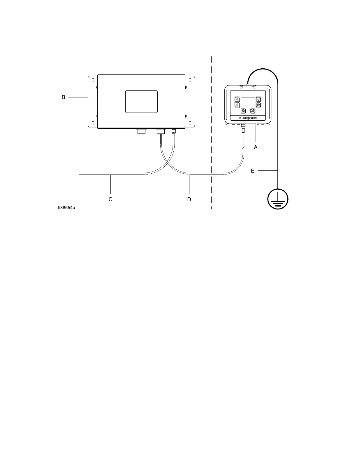
Figure1InstallationinaHazardousLocation
KEY:
KEY: KEY:
A
A A
B
B B
C
C C
D
D D
E
E E
PumpControlModule
PowerSupplyModule
PowerAccessoryCable
ISPowerCable(50ft.,15m),toterminal3.SeeCableConnection,page11.
GroundwireandclampforPumpControlModule.PN223547isnotsupplied.
83A7709B
Page 9
Installation
Grounding
Grounding Grounding
Theequipmentmustbegroundedtoreducethe
riskofstaticsparking.Staticsparkingcancause
fumestoigniteorexplode.Groundingprovidesan
escapewirefortheelectriccurrent.
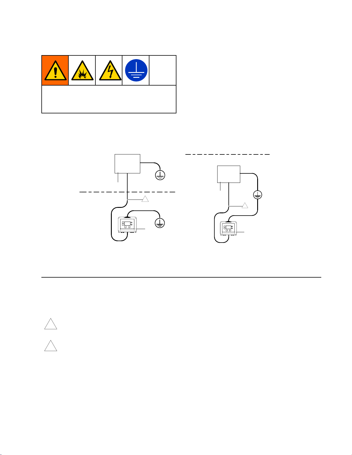
Non-
Hazardous
Location
B
1
Hazardous
Location
A
Pump
Pump Pump
Control
Control Control
Module:
Module: Module:
Groundedthrough
theISPowerCable(34)totheISbarrier
(29)inthePowerSupplyModule.(See
PowerSupplyModuleGrounding,page10.)Ifthe
mountingbracketisused,connectagroundwire(E)
tothescrewatthetopofthebrackettoatrueearth
ground.(SeeFigure1.)
Power
Power Power
Supply
Supply Supply
Module:
Module: Module:
Followthegrounding
instructionsinthePowerSupplyModulemanual
332196.
NonHazardous
Location
Hazardous
Location
B
2
A
ti20264a
PowerSupplyModuleLocatedin
Non-HazardousLocation
KEY
KEY KEY
A
A A
B
B B
PumpControlModule
PowerSupplyModuleandBarrier
PowerSupplyModuleLocatedinHaz-
ardousLocation
ti20217a
ThepowercableCANNOThavethecableshieldtiedtothecouplingnut.500VACisolation
1
isrequired.ThepowercableandcircuitboardareisolatedfromthePumpControlModule
enclosure.TheyhaveconductivepathstoSEPARATE SEPARATE
SEPARATE
grounds
grounds grounds
.
ThepowercableCANhavethecableshieldtiedtothecouplingnut.Thepowercablecoupling
2
nutandPumpControlModulehaveconductivepathstoaCOMMON COMMON
COMMON
ground
ground ground
.
3A7709B9
Page 10
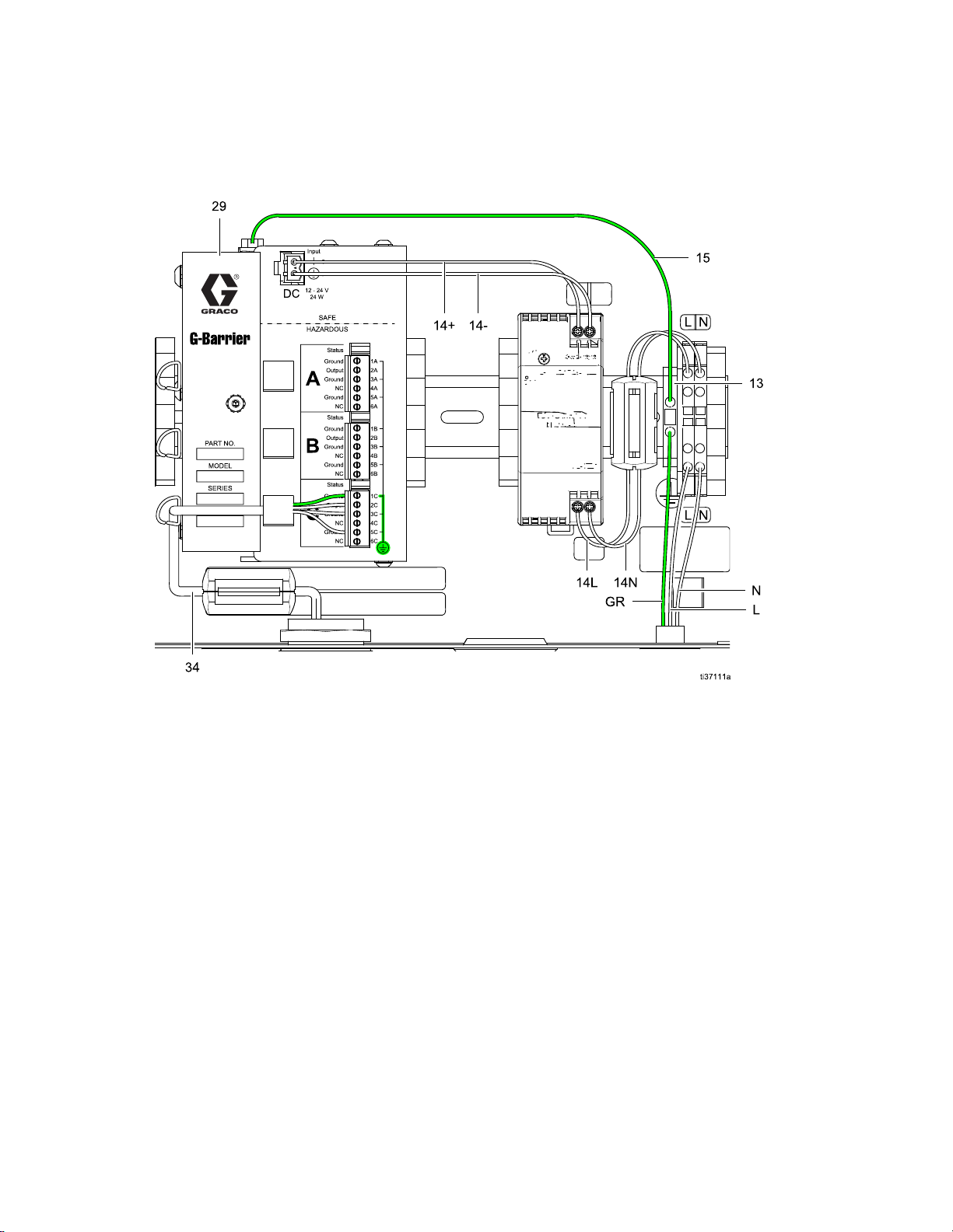
Installation
Power
Power Power
NOTE:
NOTE: NOTE:
(332196),andareincludedhereonlyforreferenceandforconsistencywithmanual332196.
Supply
Supply Supply
ThecalloutsandidenticationsonthispagereectthoseusedintheISPowerSupplyModulesmanual
Module
Module Module
Grounding
Grounding Grounding
Figure2PowerSupplyModuleGrounding
KEY:
KEY: KEY:
GR
GR GR
L
L L
N
N N
13
13 13
14+
14+ 14+
14–
14– 14–
14L
14L 14L
14N
14N 14N
15
15 15
29
29 29
34
34 34
SupplyGroundWire
SupplyLineWire
SupplyNeutralWire
GroundTerminalBlock
PowerSupplyoutputpower
PowerSupplyinputpower
Ground(fromtheGroundTerminalBlock(13)totheG-Barrier(29))
G-Barrier
ISPowerCable(fromtheG-Barrier(29)tothePumpControlModule(A,seeFigure1);
installedinfactory)
103A7709B
Page 11
Installation
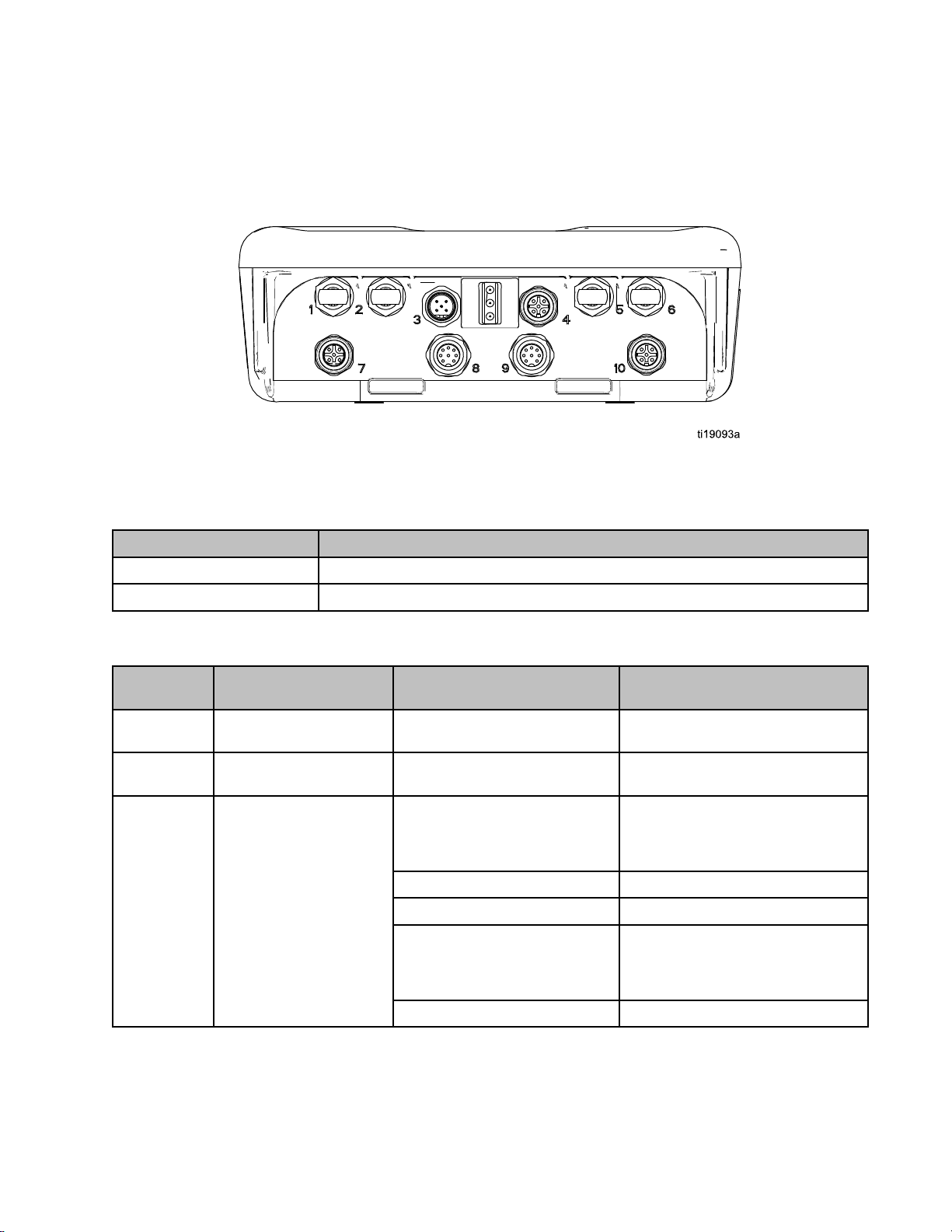
Cable
Cable Cable
Orderapoweraccessorycable(C)fromTable1.ConnectthecabletoPort3onthebottomofthecontrol
module(seeFigure3).Connecttheotherendtothepowerbarrier(seeFigure1).Connectothercables
asdescribedinTable2.
Figure3PumpControlModuleConnectors
Table
Table Table
Cable
Cable Cable
16K509
Connection
Connection Connection
Power
1 11Power Power
Part
Part Part
Accessory
Accessory Accessory
No.
No. No.
Cable
Cable Cable
Description
Description Description
Intrinsicallysafepowercable,52ft(16m)
16K615
Table
Table Table
ADCM
ADCM ADCM
Number
Number Number
1
2
3PowerInput
ADCM
2 22ADCM ADCM
Port
Port Port
Cable
Cable Cable
Connector
Connector Connector
FiberOpticReceive
FiberOpticTransmit
Intrinsicallysafepowercable,105ft(32m)
Connections
Connections Connections
Purpose
Purpose Purpose
Connection
Connection Connection
Pin1–CANLowCANdatalowlineforGCA
Pin2–PowerPowersupplyvoltage
Pin3–Common
Pin4–CANHigh
Pin5–ShieldCableshield
Notes
Notes Notes
Fiberopticreceivelineusedfor
Modbuscommunications
Fiberoptictransmitlineusedfor
Modbuscommunications
communication.CAN
communicationisnotused
onthisproduct.
Powersupplycommon
CANdatahighlinefor
GCAcommunication.CAN
communicationisnotusedonthis
product.
3A7709B
11
Page 12

Installation
Pin1–Voltage
Pin2–ReedSwitch1InputDownstrokeinputforreedswitch.
Pin3–AuxiliaryOutput
4
5
6
7
8
AuxiliaryIO
FiberOpticReceiveMirrorofberopticreceiveport1
FiberOpticTransmitMirrorofberoptictransmitport2
PressureTransducer1
4–20mAOutput1
Pin4–ReedSwitch2InputUpstrokeinputforreedswitch.
Pin5–CommonConnectedtothesysteminput
Connectedtothesysteminput
voltage(PowerInputPin2)
Inputcanbecongured
Notusedatthistime
Potentialtobeconguredas
inputcapture,butcurrentlynot
supportedincomponentlibrary.
voltagecommon(PowerInputPin
3)
Adifferentialvoltageinput.This
portcansupportmultiplepressure
transducerranges(seePressure
TransducerChapter,page27).
Monitorspumpoutletpressure.
Usedtocontroltheairinletto
thepumptoregulatethesystem
uidpressure.TheI2Pprovides
aresponsecorrelatedtotheinlet
airpressure,witha0–100%drive
signalcontrollingpressuretoa
boostvalue.
4–20mAOutput2
9
PressureTransducer2
10
Usedtocontrolanybackpressure
regulator(BPR).At4mA(0%)the
BPRiscompletelyopen,andat
20mA(100%)theBPRisfully
closed.
Adifferentialvoltageinput.This
portcansupportmultiplepressure
transducerranges.Monitorsthe
pressureattheBPR,butcanbe
usedanywhereinthesystem
(includingairinletpressure).
12
3A7709B
Page 13
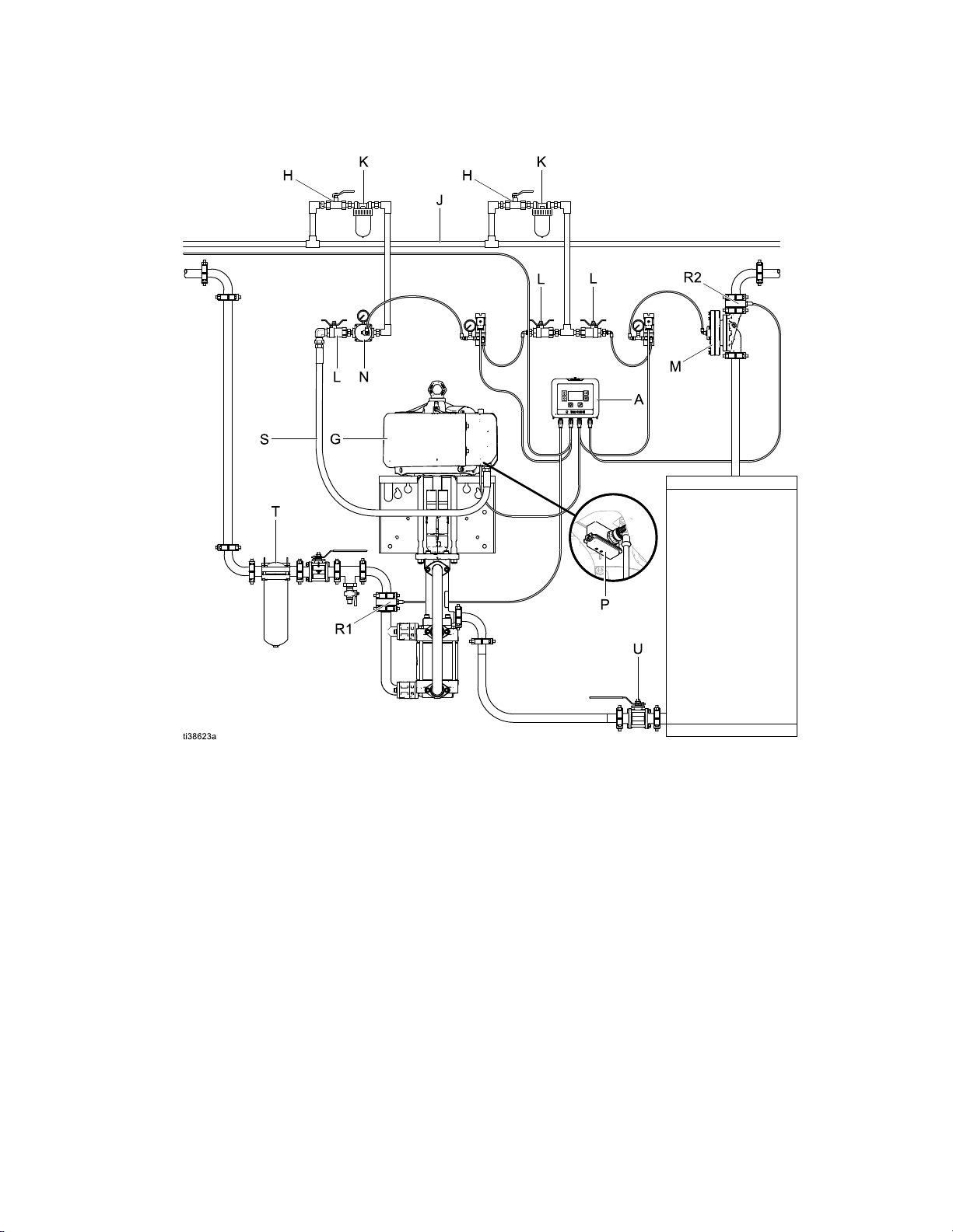
Installation
Typical
Typical Typical
Installation
Installation Installation
Figure4TypicalInstallation
KEY:
KEY: KEY:
A
A A
G
G G
H
H H
J
J J
K
K K
L
L L
M
M M
N
N N
P
P P
R1
R1 R1
R2
R2 R2
S
S S
T
T T
U
U U
Pumpcontrolmodule
Airmotor
Airlineshutoffvalve
Airsupplyline
Airlinelter
Bleed-typemasterairvalve
Back-pressureregulator(BPR)
Self-relievingpilotedairregulator
Reedswitches
Pressuretransduceratoutletofpump
PressuretransduceratBPR
Pumpinlethose
Fluidlter
Fluidinletshutoffvalve
3A7709B13
Page 14
Operation
Operation
Operation Operation
Pressure
Pressure Pressure
Unexpectedactivationofthepumpcouldresult
inseriousinjuryfrompressurizeduid,suchas
skininjection,splashinguidandmovingparts.
FollowthePressureReliefProcedurewhenyou
stopsprayingandbeforecleaning,checking,or
servicingtheequipment.
1.Ensurethepumpisoffbypressingthepump
shutdownbuttononthepumpcontrolmodule(A).
2.Closethebleed-typemasterairvalve(L).
3.Openalluiddrainvalvesinthesystem,havinga
wastecontainerreadytocatchdrainage.Leave
drainvalvesopenuntilyouarereadytospray
again.
Relief
Relief Relief
FollowthePressureReliefProcedure
wheneveryouseethissymbol.
Procedure
Procedure Procedure
Modes
Modes Modes
Pressure
Pressure Pressure
Whenthesystemisinpressurecontrolmode,the
pumpcontrolsthepressureprovidedattheoutletof
thepumpwithclosed-loopcontrol.Theunitcontrols
theairintothepumpusinganI2Pwhilemonitoring
theoutletpressurewithadifferentialpressuresensor.
Thecontrolloopupdatesatthetopofthecycle.The
pressuretargetshouldbereachedwithinvecycles.
Flow
Flow Flow
Whenthesystemisinowcontrolmode,the
pumpcontrolstoaowrateusingpressure.Flow
rateisestimatedoncycles/minuteandvolume
displacement.Thecontrolloopupdatesatthetopof
thecyclefortraditionalairmotorsandattheleftcycle
ofanAODDorGlutton
bereachedwithinvecycles.
Hybrid
Hybrid Hybrid
Whenthesystemisincontrolpumpmode,thepump
controlstoapressuretargetwhilealsoupdatingthe
BPRsetpointtocontroltheowrate.Theuseris
requiredtoenterapressuretarget,owratetarget,
andamaximumowratevalue.Thesystemrst
achievesthepressuretarget.Next,ifthesystemis
runningtoofastorslowbasedontheowratetarget,
thesystemadjuststheBPRtargettoachievetheow
ratetarget.IftheBPRtargetisateither100%or0%,
theowratetargetmaynotbeachieved.
of
Operation
of of
Operation Operation
Control
Control Control
Control
Control Control
®
.Theowratetargetshould
Open
Open Open
Whenthesystemisinopenloopmode,axedair
pressureisappliedtothepumpinlet.Thesystemwill
operatesimilarlytoamanualairregulator.Changing
thepercentagesetpointupordownadjuststheair
appliedtotheairmotorinlet.
NOTE:
NOTE: NOTE:
iftheothermodescannotbeused,butthepumpstill
needstooperate.Totroubleshooterrorcodessee
ErrorCodeTroubleshooting,page35.
14
Loop
Loop Loop
Thismodeofoperationisonlyrecommended
3A7709B
Page 15
Operation
Display
Display Display
Overlay
Overlay Overlay
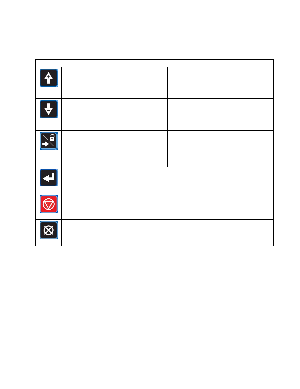
UpArrow
Down
Arrow
Right
Arrow/
Setup
Enter
Overlay
Overlay Overlay
Page
Navigation
Page Page
Navigation Navigation
Theuparrowisusedtomovetotheprevious
page.IftheuserisatPage1,pressingtheup
arrowcausesthepagestorollovertothelast
page.
Page
Navigation
Page Page
Navigation Navigation
Thedownarrowisusedtomovetothenext
page.Iftheuserisatthelastpage,pressing
thedownarrowcausesthepagestooverow
anddisplaytherstpage.
Chapter
Chapter Chapter
Therightarrowisusedtomovetothenext
chapter.Iftheuserisatthelastchapter,
pressingtherightarrowwillwraparoundtothe
rstchapter.
Field
Field Field
Pressingtheenterkeyactivatesaeldforediting,activatesthechangesinahighlightedeld,
selectsahighlightedoptioninamenu,andselectsorunselectsacheckbox.
Stop
Stop Stop
Pressingtheshutdownkeywillstopthepump.
Navigation
Navigation Navigation
Entry
Entry Entry
Pump
Pump Pump
Keys
Keys Keys
Setpoint
Setpoint Setpoint
Whentheuserisinanentryeld,theuparrow
isusedtoincrementthevalue.Ifthevalueisat
“9”,pressingtheuparrowwillcausethevalue
torolloverto“0”.
Setpoint
Setpoint Setpoint
Whentheuserisinanentryeld,thedown
arrowisusedtodecrementthevalue.Ifthe
valueisat“0”,pressingthedownarrowwill
causethevaluetorolloverto“9”.
Setup
Setup Setup
ToenterorexitSetup,theuserwillpressand
holdtherightarrowkeyforthreeseconds.
Incrementation
Incrementation Incrementation
Decrementation
Decrementation Decrementation
Shutdown
Field
Entry
Field Field
Entry Entry
Whentheuserisinamenuoranumericeld,pressingthecancelkeycausesthedisplayto
exiteldentrymodeandrevertbacktothepreviousscreen.
Cancel
3A7709B15
Page 16
Operation
Module
Module Module
Therearetwosetsofscreens(Books):Runand
Setup.RunandSetupbookscontainchapters,
andeverychaptercontainspages.Chaptersare
accessedbyusingtherightarrowkey.Atthebottom
ofthescreentherearedotstoindicatethenumberof
chaptersandtohighlightthecurrentchapter.Ifyou
navigatepastthechapteryouwanttodisplay,you
needtocontinuepressingrightarrowkeytowrap
backtothechapteryouwouldliketoupdate.
Pagesareaccessedusingtheupanddownarrows.
Attherightsideofthescreentherearedotsto
indicatethenumberofpagesinthischapterandto
highlightthecurrentpage.
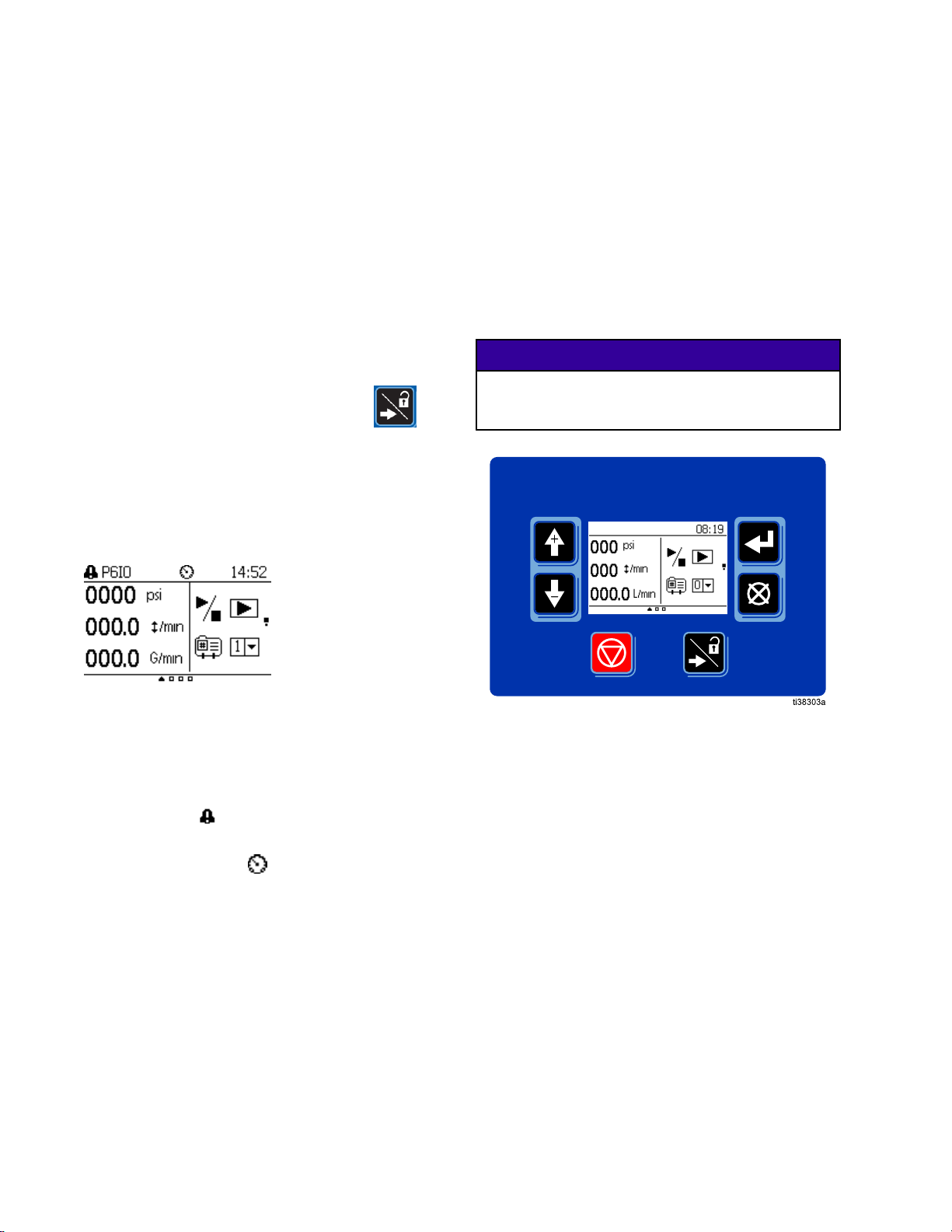
Pressandholdtherightarrow/lockicon(
threesecondstoenterorexitSetup.
NOTE:
NOTE: NOTE:
loadrequirements.
Example:ThissetofRunScreenshasthreechapters
(indicatedbythebottomofthescreen)andtwo
pages(indicatedbythesquaresontherightsideof
thescreen).
Screens
Screens Screens
Thescreenautomaticallydimsbasedonthe
Module
Module Module
Thegurebelowisaviewofthecontrolmodule
displayandkeys.Overlay,page15,explains
thefunctionofthemembranekeysonthecontrol
module.Asyoumovethroughthescreens,you
willnoticethatmostinformationiscommunicated
usingiconsratherthanwordstosimplifyglobal
communication.Thedetailedscreendescriptionsin
RunScreens,page17,andSetupScreens,page22,
explainwhateachiconrepresents.Thetwokeysare
membranebuttonswhosefunctioncorrelateswith
thescreencontenttotheimmediateleftofthebutton.
Topreventdamagetothebuttons,donotpressthe
buttonswithsharpobjectssuchaspens,plastic
)for
cards,orngernails.
Keys
Keys Keys
NOTICE
NOTICE NOTICE
Module
Module Module
TheModuleTopMenuonlydisplayson
RunScreens,page17andshowsthefollowing:
Error
•Error Error
ErrorCodeTroubleshooting,page35.
Current
•Current Current
SeeProleCongurationPage,page22.
Time
•Time Time
163A7709B
Menu
Menu Menu
Codes
Codes Codes
Prole
Prole Prole
Bar
Bar Bar
See
Mode
Mode Mode
(PressureModeshown).
Figure5ControlModuleKeypadandDisplay
Page 17
RunScreens
Run
Run Run
Unexpectedactivationofthepumpcouldresult
inseriousinjuryfrompressurizeduid,suchas
skininjection,splashinguidandmovingparts.
FollowthePressureReliefProcedurewhenyou
stopsprayingandbeforecleaning,checking,or
servicingtheequipment.
Pump
Pump Pump
Pump
Pump Pump
Screens
Screens Screens
Control
Control Control
Control
Control Control
Chapter
Chapter Chapter
Page
Page Page
1
1 1
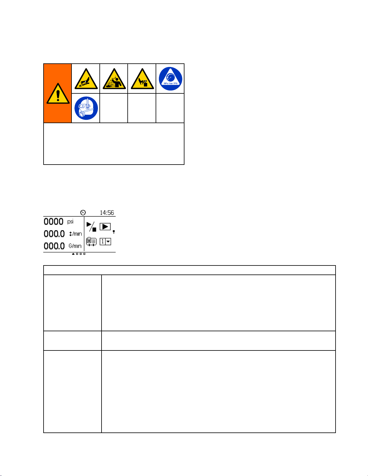
RunScreensarecomprisedoftheruntime
informationthatthesystemismonitoringand
controlling,suchas:CurrentFlowRate,Cycle
PerMinute,Pressure,ActiveProle,etc.See
Overlay,page15,forinformationonhowtomake
selectionsandenterdata.
Figure6PumpControlPage1
Displaysthecurrentaveragepressureattheoutletofthepumpinpressureunits
selectedinsetup.
Range:
Current
Current Current
Cycles
Cycles Cycles
Current
Current Current
Pressure
Pressure Pressure
Per
Minute
Per Per
Minute Minute
Flow
Rate
Flow Flow
Rate Rate
•PSI:0–9999
•Bar:0.0–999.9
•MPa:0.00–99.99
Displaysthecurrentaveragecyclesrateofthepumpincyclesperminute.
Range:00.0–99.9CPM
Displaythecurrentowrateofthepump.Numberiscalculatedbasedoncycles
perminuteanddisplacement.Thevalueisdisplayedintheowrateunitsspecied
insetup.
Range:
•Gallons/min:0.0–999.9
•Liters/min:0.0–999.9
•CC/min:0–99999
•Oz/min:0–99999
•CPM:0.0–99.9
Pump
Pump Pump
Control
Control Control
Page
Page Page
Key
1 11Key Key
3A7709B
17
Page 18
RunScreens
Commandthepumptostartorstop,asindicatedbyaplayorpauseicon.Pressto
togglebetweenthetwoicons.
Run/Stop
Run/Stop Run/Stop
Prole
Prole Prole
Pump
Pump Pump
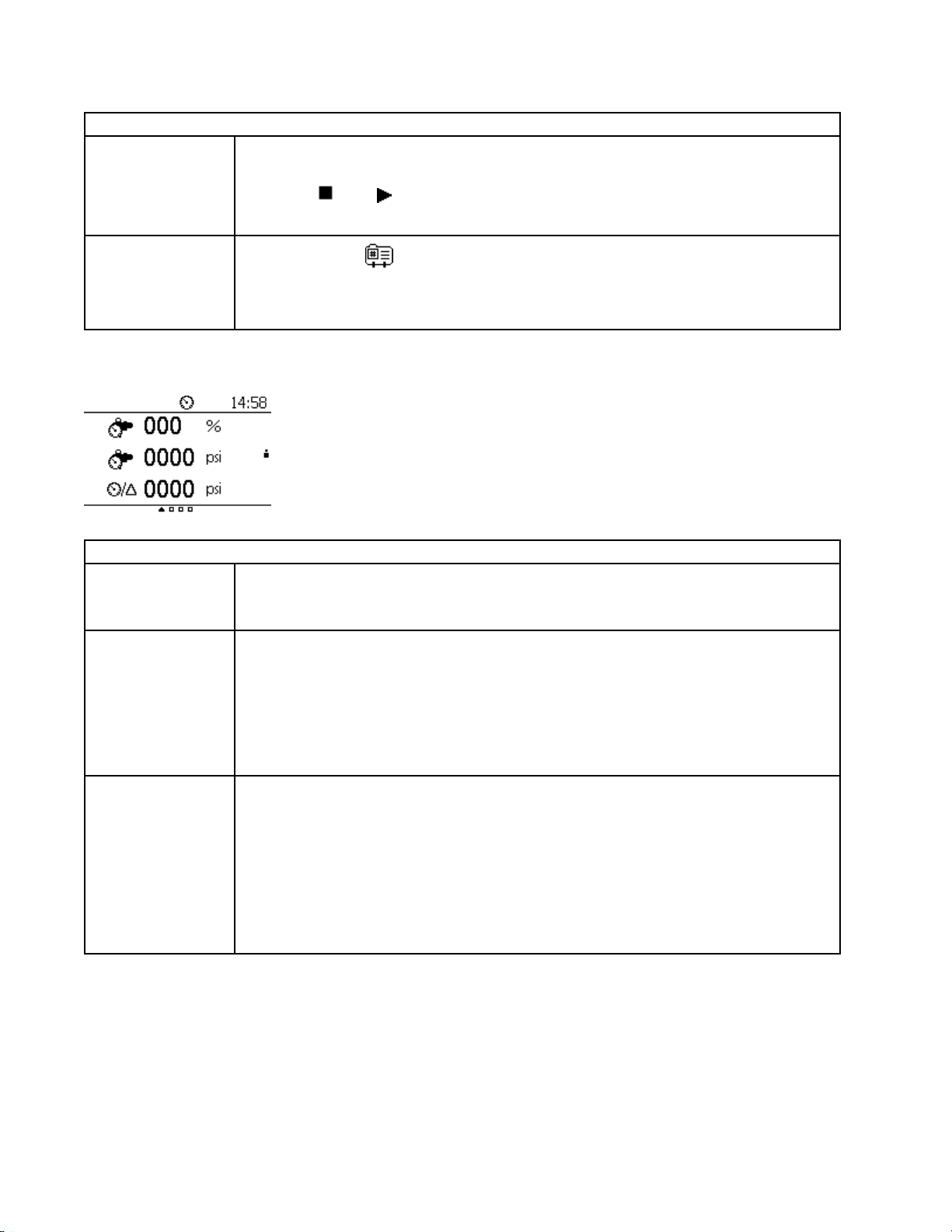
Figure7PumpControlPage2
Back
Back Back
Regulator
Regulator Regulator
Select
Select Select
Control
Control Control
Pressure
Pressure Pressure
Percent
Percent Percent
Output
Output Output
Range:0(
Default:0(Pause)
Selecttheprole(
Range:1–4
Default:Lastvaluethepumpwasrunning
Page
Page Page
2
2 2
Displaysthecurrentpercentoutputbeingappliedtothebackpressureregulator.0%
indicatesfullyopen,while100%indicatesfullyclosed.
Range:0–100%
Displaystheaveragepressureindicatedbypressuresensor2.Acommonapplication
isthepressureattheBackPressureRegulator.
Pump
Pump Pump
)–1( )
Pump
Pump Pump
Control
Control Control
)torunonthepump.ProlesareconguredinSetup.
Control
Control Control
Page
Page Page
Page
Page Page
Key
1 11Key Key
Key
2 22Key Key
Back
Pressure
Back Back
Pressure Pressure
Regulator
Regulator Regulator
Delta
Delta Delta
Pressure
Pressure Pressure
Pressure
Pressure Pressure
Range:
•PSI:0–999
•Bar:0.0–99.9
•MPa:0.00–9.99
Displaysthedifferenceinpressurebetweentheoutletofthepumpandthesecond
pressuretransducer.Commonapplicationistomonitorpressuredropacrossthe
circulationline.Inthatapplicationthesecondpressuretransducerisinstalledatthe
BPR.
Range:
•PSI:0–999
•Bar:0.0–99.9
•MPa:0.00–9.99
183A7709B
Page 19

RunScreens
Totalizer
Totalizer Totalizer
Totalizer
Totalizer Totalizer
Figure8TotalizerPage
Pump
Pump Pump
Batch
Batch Batch
Maintenance
Maintenance Maintenance
Page
Page Page
Totalizer
Totalizer Totalizer
Totalizer
Totalizer Totalizer
Totalizer
Totalizer Totalizer
Chapter
Chapter Chapter
Totalizer
Totalizer Totalizer
Thepumptotalizerdisplaysthetotalcycles/volumethatthepumphasdisplaced.
Thiseldisnotresettable.
Thebatchtotalizerdisplaysthetotalvolumethatthepumphasdisplacedfora
particularjob.Batchtotalizercanberesetinsetup.
Themaintenancetotalizerdisplaysthecurrentvolumethatthepumphasdisplaced
sincethelasttimemaintenancewasperformed.Maintenancetotalizerhastobereset
insetupaftereachmaintenancecycle.
Page
Key
Page Page
Key Key
NOTE:
NOTE: NOTE:
Allcounterscountup.
3A7709B19
Page 20

RunScreens
Agitator
Agitator Agitator
Thisscreendisplaysinformationforcontrollingan
electricagitatorusingthesupervisortopasson
thecontrolsetpointtoaVariableFrequencyDrive
(VFD),alsoknownasaninverter.
Figure9AgitatorChapter
Enable/Disable
Enable/Disable Enable/Disable
Speed
Speed Speed
Local
Local Local
Chapter
Chapter Chapter
Selecttheboxtoenableordisabletheagitator.
Agitator
Agitator Agitator
Setpoint
Setpoint Setpoint
Mode
Mode Mode
Setthespeedsetpointfortheagitatorfrom0–100%.
Selectthisboxtoputagitatorcontrolinlocalonlymode.SetpointandEnable/Disable
requestsfromPLC/Supervisorwillbeignored.
Run
Screen
Run Run
Screen Screen
Key
2 22Key Key
203A7709B
Page 21

RunScreens
Event
Event Event
Theerrorsscreenisutilizedtoshowanysystem
errorsthathaveoccurred.Theerrorswillbe
displayedwithoneerrorperrow.Theprevious20
errorscanbedisplayedatanytimeoverthefourerror
screens.Alackofanerrorisshownwithhyphens‘-‘.
Theerrorsaredisplayedmostrecentrst.
Figure10EventLogChapter
Log
Chapter
Log Log
Chapter Chapter
Event
Log
1
Event Event
Log Log
1 1
Event
Log
Event Event
Log Log
2 2
Event
Log
Event Event
Log Log
3 3
Event
Log
Event Event
Log Log
4 4
Displaysthelast1–5Events.
2
Displaysthelast6–10Events.
3
Displaysthelast11–15Events.
4
Displaysthelast16–20Events.
Event
Log
Event Event
Key
Log Log
Key Key
3A7709B
21
Page 22

SetupScreens
Setup
Setup Setup
UsetheSetupscreensforpumpsettingsandaccessoryfeatures.SeeOverlay,page15,forinformationon
howtomakeselectionsandenterdata.
Inactiveeldsaregrayedoutonascreen.
Prole
Prole Prole
Prole
Prole Prole
PressureModeFlowModeHybridMode
Prole
Prole Prole
Screens
Screens Screens
Chapter
Chapter Chapter
Conguration
Conguration Conguration
Number
Number Number
Page
Page Page
Prole
Prole Prole
Selectthenumberofthedesiredprolesfromthemenu:1–4.
Selecttheoperatingmodeoftheprole.
Conguration
Conguration Conguration
Page
Key
Page Page
Key Key
OpenLoopMode
Range:
•Pressure(
owratelimitedbythemaximumvalue.
Prole
Prole Prole
Mode
Mode Mode
Target
Target Target
•Flow()—Whenselected,theunitwilloperateontheowsetpointwithapressure
limitedbythemaximumvalue.
•Hybrid(
automaticallyadjusttheBPRtocontroltheow.
•OpenLoop—Whenselectedtheunitwilloperateonapercentagesetpointfrom0100%.Thisdirectlycorrelatestotheinletairtothepump.
Targetelds(seethefollowingPressure,Flow,andBackPressureRegulatorelds)
areupdatedbasedontheProleMode.
•PressureMode:
–TargetPressure( )
–BPRSetpoint()
•FlowMode:
–TargetFlow(
–BPRSetpoint( )
•HybridMode:
)—Whenselected,theunitwilloperateonthepressuresetpointwitha
)—Whenselected,theunitwilloperateonthepressuresetpoint,and
)
–TargetPressure( )
–TargetFlow()
22
3A7709B
Page 23

SetupScreens
Prole
Prole Prole
SetsthetargetpressurewhentheProleModeeldissettoPressure(
(
).
Range:
Pressure
Pressure Pressure
Flow
Flow Flow
•PSI:0–9999
•Bar:0.0–999.9
•MPa:0.00–99.99
Default:0.0
SetsthetargetowratewhentheProleModeeldissettoFlow(
().
Range:
•Gallons/min:0.0–999.9
•Liters/min:0.0–999.9
•CC/min:0–99999
•Oz/min:0–99999
•CPM:0.0–99.9
Default:0.0
SetstheBackPressureRegulatorpercentagewhenProleModeeldissetto
Pressure(
)orFlow( ).
Conguration
Conguration Conguration
Page
Key
Page Page
Key Key
)orHybrid
)orHybrid
TorunHybridMode(
Back
Pressure
Back Back
Pressure Pressure
Regulator
Regulator Regulator
(BPR)
(BPR) (BPR)
thesystemisstable.AftertheHybridmodeprolestarts,thesystemwillautomatically
adjusttheBPRpercentbasedonthestartingpercentagevalue.Ifthesystemstallsfor
15seconds,thentheBPRpercentagewillautomaticallydecrease.
Range:
•BPR:0–100%
Default:0
),enterastartingBPRpressure.Thisisrequiredtoensure
3A7709B23
Page 24

SetupScreens
Limit
Conguration
Limit Limit
Conguration Conguration
Figure11LimitCongurationPage
Page
Page Page
NOTE:
NOTE: NOTE:
conguredonProlePage3(see
EventCongurationPage,page26).
Limit,Deviation,orAlarmare
Prole
Prole Prole
ThiseldisactivewhentheproleisinPressuremode,anddisabledwheninFlowor
Hybridmode.
NOTE:
NOTE: NOTE:
stalls,thenthesystemwillkeepincreasingthepressureevery15secondstomovethe
pumporuntilitreachesthespeciedHighPressurelimit.
Thiseldcanhavethreedifferenteventtypes:
•Limit:Limitsthemaximumpressurethemotorcangenerate.
Pressure
Pressure Pressure
Pressure
Pressure Pressure
High
High High
Low
Limit
Low Low
Limit Limit
•Deviation:Generatesadeviationwhenthemotorpressureexceedsthelimit.
Limit
Limit Limit
•Alarm:Generatesanalarmandshutsdownthemotorafterthelimitisexceeded
Thiseldcanhavethreedifferenteventtypes:
•Limit:Limitstheminimumpressurethemotorcangenerate.
•Deviation:Generatesadeviationwhenthemotorpressuredropsbelowthelimit.
•Alarm:Generatesanalarmandshutsdownthemotorwhentheforcedropsbelow
HighPressurelimitshouldbespeciedwheninFlowmode.Ifthesystem
fortwocycles.
–Range:
♦PSI:0–9999
♦Bar:0.0–999.9
♦MPa:0.00–99.99
–Default:0.0
thelimitfortwocycles.
–Range:
Conguration
Conguration Conguration
Page
Key
Page Page
Key Key
♦PSI:0–9999
♦Bar:0.0–999.9
♦MPa:0.00–99.99
–Default:0.0
24
3A7709B
Page 25

SetupScreens
Prole
Prole Prole
ThiseldisactivewhentheproleisinFlowmode,andisdisabledwheninPressure
orHybridmode.
Thiseldcanhavethreedifferenteventtypes:
•Limit:Limitsthemaximumowratethesystemcangenerate.
•Deviation:Generatesadeviationwhenthesystemowrateexceedsthelimit.
•Alarm:Generatesanalarmandshutsdownthemotorwhenthelimitisexceeded
Flow
Rate
Flow Flow
High
Rate Rate
High High
Limit
Limit Limit
fortwocycles.
–Range:
♦Gallons/min:0.0–999.9
♦Liters/min:0.0–999.9
♦CC/min:0–99999
♦Oz/min:0–99999
♦CPM:0.0–999.9
–Default:0.0
Thiseldcanhavethreedifferenteventtypes:
•Limit:Limitstheminimumowratethesystemcangenerate.
•Deviation:Generatesadeviationwhenthesystemowratedropsbelowthelimit.
•Alarm:Generatesanalarmandshutsdownthemotorwhentheowratedrops
belowlimitfortwocycles.
Conguration
Conguration Conguration
Page
Key
Page Page
Key Key
–Range:
Flow
Rate
Low
Flow Flow
Rate Rate
Limit
Low Low
Limit Limit
♦Gallons/min:0.0–999.9
♦Liters/min:0.0–999.9
♦CC/min:0–99999
♦Oz/min:0–99999
♦CPM:0.0–999.9
–Default:0.0
3A7709B25
Page 26

SetupScreens
Event
Event Event
Figure12EventCongurationPage
Conguration
Conguration Conguration
Limit:Limitsthemaximumpressureorforcethemotorcangenerate.
Deviation:Generatesadeviationwhenthemotorpressureexceedsthelimit.
Pressure/Force
Pressure/Force Pressure/Force
High
Event
High High
Pressure/Force
Pressure/Force Pressure/Force
Low
Low Low
Event Event
Type
Event Event
Type Type
Event
Type
Type Type
Alarm:Generatesanalarmandshutsdownthemotorwhenthelimitisexceeded.
•Range:Limit,Deviation,Alarm
•Default:Limit
Limit:Limitstheminimumpressureorforcethemotorcangenerate.
Deviation:Generatesadeviationwhenthemotorpressuredropsbelowthelimit.
Alarm:Generatesanalarmandshutsdownthemotorwhentheforcedropsbelow
thelimit.
•Range:Limit,Deviation,Alarm
•Default:Limit
Limit:Limitsthemaximumowratethesystemcangenerate.
Page
Page Page
Prole
Prole Prole
Conguration
Conguration Conguration
Page
Key
Page Page
Key Key
Deviation:Generatesadeviationwhenthesystemowrateexceedsthelimit.
Flow
High
Flow Flow
Flow
Flow Flow
Event
High High
Event Event
Type
Type Type
Low
Event
Low Low
Event Event
Type
Type Type
Alarm:Generatesanalarmandshutsdownthemotorwhenthelimitisexceeded.
•Range:Limit,Deviation,Alarm
•Default:Limit
Limit:Limitstheminimumowratethesystemcangenerate.
Deviation:Generatesadeviationwhenthesystemowratedropsbelowthelimit.
Alarm:Generatesanalarmandshutsdownthemotorwhentheowratedropsbelow
thelimit.
•Range:Limit,Deviation,Alarm
•Default:Limit
263A7709B
Page 27

SetupScreens
Pressure
Pressure Pressure
Setup
Setup Setup
Figure13SetupPressureSensor1
Pressure
Pressure Pressure
Transducer
Transducer Transducer
Sensor
Sensor Sensor
Offset
Offset Offset
Transducer
Transducer Transducer
Pressure
Pressure Pressure
Sensitivity
Sensitivity Sensitivity
Voltage
Voltage Voltage
Sensor
Sensor Sensor
Usethemenutoselecttheattachedtransduceroption.Thedefaultvalueistheno
transducericon( ).
Range:Notransducer,500psi,or7500psi.
Default:500psi
Enterthecalibrationscalefactorintothiseld.Eachpressuretransducerhasaunique
calibrationscalefactor.
Range:00.0000–99.9999mV/V
Default:00.0000mV/V
Entertheoffsetfactorintothiseld.Eachpressuretransducerhasauniqueoffset
voltagefactor.
Range:0.00–9.99mV/V
Chapter
Chapter Chapter
1
1 1
Setup
Setup Setup
Pressure
Pressure Pressure
Sensor
Sensor Sensor
Key
1 11Key Key
Default:0.00mV/V
3A7709B
27
Page 28

SetupScreens
Setup
Setup Setup
Figure14SetupPressureSensor2
Pressure
Pressure Pressure
Pressure
Pressure Pressure
Transducer
Transducer Transducer
Sensor
Sensor Sensor
Sensitivity
Sensitivity Sensitivity
Offset
Voltage
Offset Offset
Voltage Voltage
Sensor
Sensor Sensor
2
2 2
Usethemenutoselecttheattachedtransduceroption.Thedefaultvalueistheno
transducericon( ).When100psiisselected,thedeltapressurefeatureis
disabled.Itisassumedthattheairinlettothepumpismonitored.
Range:Notransducer,500psi,or7500psi.
Default:Notransducer
Enterthecalibrationscalefactorintothiseld.Eachpressuretransducerhasaunique
calibrationscalefactor.
Range:00.0000–99.9999mV/V
Default:00.0000mV/V
Entertheoffsetfactorintothiseld.Eachpressuretransducerhasauniqueoffset
voltagefactor.
Range:0.00–9.99mV/V
Setup
Setup Setup
Pressure
Pressure Pressure
Sensor
Sensor Sensor
Key
2 22Key Key
Default:0.00mV/V
283A7709B
Page 29

SetupScreens
Pump
Pump Pump
Pump
Pump Pump
Pump
Pump Pump
Setup
Setup Setup
Setup
Setup Setup
Pump
Pump Pump
Lower
Lower Lower
Setup
Setup Setup
Chapter
Chapter Chapter
Screen
Screen Screen
Screen
Screen Screen
1
1 1
Pump
Pump Pump
Ratio
Ratio Ratio
Size
Size Size
2
2 2
Enterthepumpratio.Referencetheproductmanualifthevalueisnotknown.
ChecktheboxtolockouttheagitatoreldintheRunscreens.
Setup
Setup Setup
Screen
Screen Screen
Key
1 11Key Key
Pump
Pump Pump
Pressure
Pressure Pressure
Volume
Volume Volume
Flow
Flow Flow
Units
Units Units
Units
Units Units
Rate
Units
Rate Rate
Units Units
Selectthepressureunits:
•psi
•bar(default)
•MPa
Selectthevolumeunits:
•liters(default)
•gallons
•cc
Selecttheowrateunits:
•L/min(default)
•gpm
•cc/min
•oz/min
•cycles/min
Setup
Setup Setup
Key
Key Key
3A7709B29
Page 30

SetupScreens
Diagnostic
Diagnostic Diagnostic
Setup
Setup Setup
Figure15SetupDiagnostic
Current
Current Current
Current
Current Current
Totalizer
Totalizer Totalizer
Setup
Setup Setup
Chapter
Chapter Chapter
Diagnostic
Diagnostic Diagnostic
Setup
Setup Setup
Readback
Readback Readback
—
Port
— —
—
— —
8
Port Port
8 8
Readback
Readback Readback
Port
9
Port Port
9 9
Chapter
Chapter Chapter
Totalizer
Totalizer Totalizer
Thisnon-editableeldreadstheinstantaneousoutputcurrentinmAformotorinlet
I2Poutput.
Thisnon-editableeldreadstheinstantaneousoutputcurrentinmAforBackPressure
RegulatorI2Poutput.
Diagnostic
Diagnostic Diagnostic
Outputs
Outputs Outputs
Key
Key Key
Figure16SetupTotalizer
Maintenance
Maintenance Maintenance
Maintenance
Maintenance Maintenance
Setpoint
Setpoint Setpoint
Set
Totalizer
Set Set
Totalizer Totalizer
Countsdownthenumberofcyclesbeforeamaintenanceeventistriggered.A
Cycles
Cycles Cycles
maintenanceeventistriggeredwhenthevaluehitszero.Thiseldisresettable.
Range:0–9999999cycles
Default:0
Setstheamountofcyclesinamaintenancecycle.
Range:0–9999999cycles
Default:0
Key
Key Key
303A7709B
Page 31

SetupScreens
Modbus
Modbus Modbus
UsethisscreentosettheModbuspreferences.
NOTE:
NOTE: NOTE:
Modbus
Modbus Modbus
Serial
Serial Serial
Chapter
Chapter Chapter
ThefollowingarexedModbussettings,whichcannotbesetorchangedbytheuser:
DataBits:8
StopBits:2
Parity:None
Modbus
Modbus Modbus
Location
Location Location
Node
ID
Node Node
ID ID
Port
Baud
Port Port
Baud Baud
Rate
Rate Rate
Setup:
Setup: Setup:
Selectlocal orremote fromthemenu.Thissettingappliestotheselected
pumponly.
LocalmodeallowsyoutoviewchangesovertheModbusnetwork,butyoucannot
makechangesovertheModbusnetwork.Remotemodeallowsyoutobothviewand
changeinformationovertheModbusnetwork.
EnterorchangetheModbusnodeID.Thevalueisbetween1and246.Eachpump
requiresauniquenodeID,whichidentiesthatpumpifmorethanonepumpis
connectedtothedisplay.
Selecttheserialportbaudratefromthemenu.Thisisasystem-widesetting.
•38400kbps
•57600kbps(default)
•115200kbps
SelecttheModbuseventtype:
Screen
Screen Screen
1
1 1
Modbus
Modbus Modbus
Setup
Setup Setup
Key
Key Key
Modbus
Modbus Modbus
Setup:
Setup: Setup:
Screen
Screen Screen
2
2 2
Modbus
Modbus Modbus
Event
Event Event
None
Deviation
Alarm
3A7709B31
Page 32

SetupScreens
Miscellaneous
Miscellaneous Miscellaneous
Setup
Setup Setup
Figure17SetupMiscellaneous1
Off
Off Off
Miscellaneous
Miscellaneous Miscellaneous
Auto
Restart
Auto Auto
Restart Restart
Production
Production Production
Backlight
Backlight Backlight
Time
Time Time
Chapter
Chapter Chapter
1
1 1
Whenenabledifthepumplossespoweritwillautomaticallyresumeoperationinthe
lastproleitwasrunningbeforepowerloss.
Range:0–1
Default:0
Mode
Mode Mode
- --out out
Enabletheoffproductionprolemode.Thisfeatureturnsprole4intotheoff
productionprole..
Specifythebacklighttimeoutinminutes.Ifthedisplayisinactiveforxamountoftime
out
thedisplaybacklightwillturnoff.Ifvalueis0thenbacklightwillalwaysremainon.
Setup
Setup Setup
Maintenance
Maintenance Maintenance
Key
1 11Key Key
Range:0–99
Default:10
323A7709B
Page 33

SetupScreens
Setup
Setup Setup
Figure18SetupMiscellaneous2
Miscellaneous
Miscellaneous Miscellaneous
Date
Order
Date Date
Order Order
Set
Date
Set Set
Date Date
Set
Time
Set Set
Time Time
2
2 2
Usethedropdownmenutoselectthedesireddateorientation.
Range:MM/DD/YY,DD/MM/YY,orYY/MM/DD
Default:MM/DD/YY
Usetheeldtosetthecurrentdate.
MonthRange:01-12
DayRange:01-31
YearRange:00-99
Usetheeldtosetthecurrenttime.
HourRange:01-23
MinuteRange:01-59
Setup
Setup Setup
Maintenance
Maintenance Maintenance
Key
2 22Key Key
3A7709B33
Page 34

SetupScreens
Setup
Setup Setup
Figure19SetupMiscellaneous3
Miscellaneous
Miscellaneous Miscellaneous
Passcode
Passcode Passcode
Passcode
Passcode Passcode
Prole
Prole Prole
Enable
Enable Enable
Lock
Lock Lock
3
3 3
Enablespasscodeentrywhenuserenterssetup.
Range:Enable/Disable
Default:Disable
Checktheboxnexttothelockicontoenableapasscodeonthedevice.Enterthe
desiredpasscodeintheeldbelowthebox.Uponacceptingthesechanges,pressing
thelocksoftkeywilllocktheaccesstothesettingsofthedevice.Apasswordof0000
isinvalidandwillnotlockthesettingsofthedevice.
Range:0000–9999
Default:0000
Checktheboxnexttoprolelockicon( )tolockouttheuserfrommodifying
thecurrentproleontheRunscreens.
Setup
Setup Setup
Maintenance
Maintenance Maintenance
Key
3 33Key Key
Range:Enable/Disable
Default:Disable
343A7709B
Page 35

ErrorCodeTroubleshooting
Error
Error Error
Errorcodescantakethreeforms:
•Alarm
downthepump.
•Deviation
maycontinuetorunpastthesetlimitsuntilthe
system’sabsolutelimitsarereached.
•Advisory
tooperate.
NOTE:
NOTE: NOTE:
pressure(Pcodes)canbedesignatedasalarmsor
deviations.SeeEventCongurationPage,page26.
Event
Event Event
Code
Code Code
C3G1
C3G1 C3G1
Code
Code Code
:alertsyoutothealarmcauseandshuts
:alertsyoutotheproblem,butpump
:informationonly.Pumpwillcontinue
OnAdvancedmotors,ow(Kcodes)and
ModbusCommunication
Troubleshooting
Troubleshooting Troubleshooting
Event
Event Event
Deviation
NOTE:
NOTE: NOTE:
thecodeisassociatedwiththedisplayonly.
NOTE:
NOTE: NOTE:
codeisaplaceholderforthenumberofthepump
wheretheeventoccurred.
NOTE:
NOTE: NOTE:
indicatoronthemotor.Theblinkcodegivenbelow
indicatesthesequence.Forexample,blinkcode1–2
indicates1blink,then2blinks;thesequencethen
repeats.
NOTE:
NOTE: NOTE:
indicatorofwhichpumpisactive.
Event
Event Event
Deviation
Intheerrorcodeslistedbelow,an“X”means
Intheerrorcodeslistedbelow,a“_”inthe
Theblinkcodeisdisplayedusingthepower
Ablinkcodeof9isnotanerrorcode,butan
Type
Type Type
Displaydetectsalossof
Modbuscommunicationwhen
Modbuseventtypeissetupto
beadeviation.Triggereventif
therehasnotbeenaModbus
readeventwithin1second.
Description
Description Description
C4G1
C4G1 C4G1
DD90
DD90 DD90
DK61
DK61 DK61
DK62
DK62 DK62
K1D1
K1D1 K1D1
K2D1
K2D1 K2D1
ModbusCommunicationAlarm
ReedSwitchFailure
PumpDivingDownStroke
PumpCavitationUpStroke
MinimumFlowRateAlarmAlarm
MinimumFlowRateDeviationDeviation
Alarm
Deviation
DeviationThetimetocompleteadown
DeviationThetimetocompleteanup
Displaydetectsalossof
Modbuscommunicationwhen
Modbuseventtypeissetupto
beanalarm.Triggereventif
therehasnotbeenaModbus
readeventwithin1second.
Systemisnotdetectingareed
switch.
strokeissignicantlyshorterto
completethananupstroke.
strokeissignicantlyshorter
thantocompleteadown
stroke.
Averageowratehasdropped
belowminimumowrate
thresholdspeciedforactive
prole.Eventwilltriggerif
minimumowrateeventis
conguredforalarm.
Averageowratehasdropped
belowminimumowrate
thresholdspeciedforactive
prole.Eventwilltriggerif
minimumowrateeventis
conguredfordeviation.
3A7709B35
Page 36

ErrorCodeTroubleshooting
Event
Event Event
Code
Code Code
K3D1
K3D1 K3D1
K4D1
K4D1 K4D1
P1I1
P1I1 P1I1
P2I1
P2I1 P2I1
MaximumFlowRateDeviationDeviation
MaximumFlowRateAlarmAlarm
MinimumPressure1AlarmAlarmAveragepumpoutletpressure
MinimumPressure1DeviationDeviationAveragepumpoutletpressure
Event
Event Event
Event
Type
Event Event
Type Type
Averageowratehasrisen
abovemaximumowrate
thresholdspeciedforactive
prole.Eventwilltriggerif
maximumowrateeventis
conguredfordeviation.
Averageowratehasrisen
abovemaximumowrate
thresholdspeciedforactive
prole.Eventwilltriggerif
maximumowrateeventis
conguredforalarm.
hasdroppedbelowminimum
pressurethresholdspecied
foractiveprole.Eventwill
triggerifminimumpressure
eventisconguredforalarm.
hasdroppedbelowminimum
pressurethresholdspeciedfor
activeprole.Eventwilltrigger
ifminimumpressureeventis
conguredfordeviation.
Description
Description Description
P3I1
P3I1 P3I1
P4I1
P4I1 P4I1
P6I1
P6I1 P6I1
P1CB
P1CB P1CB
P2CB
P2CB P2CB
MaximumPressure1DeviationDeviationAveragepumpoutletpressure
hasrisenabovemaximum
pressurethresholdspeciedfor
activeprole.Eventwilltrigger
ifmaximumpressureeventis
conguredfordeviation.
MaximumPressure1AlarmAlarmAveragepumpoutletpressure
hasrisenabovemaximum
pressurethresholdspecied
foractiveprole.Eventwill
triggerifmaximumpressure
eventisconguredforalarm.
PressureTransducer1FaultAlarmForunitswithoutclosedloop
pressurecontrol:Transducer1
isenabledbutnotdetected.
MinimumPressure2AlarmAlarmAveragepressureattransducer
2hasdroppedbelowminimum
pressurethreshold.Eventwill
triggerifminimumpressure
eventisconguredforalarm.
MinimumPressure2DeviationAlarmAveragepressureattransducer
2hasdroppedbelowminimum
pressurethreshold.Event
willtriggerifminimum
pressureeventiscongured
fordeviation.
363A7709B
Page 37

ErrorCodeTroubleshooting
Event
Event Event
Code
Code Code
P3CB
P3CB P3CB
P4CB
P4CB P4CB
P6CB
P6CB P6CB
P6D1
P6D1 P6D1
P6P1
P6P1 P6P1
MaximumPressure2DeviationAlarmAveragepressureattransducer
MaximumPressure2AlarmAlarmAveragepressureattransducer
PressureTransducer2FaultAlarmTransducer2isopencircuit.
MotorInletI2PisdisconnectedAlarmPort8isenabledandthe
BackPressureRegulator
I2Pisdisconnected
Event
Event Event
Event
Event Event
Type
Type Type
2hasrisenabovemaximum
pressurethreshold.Event
willtriggerifmaximum
pressureeventiscongured
fordeviation.
2hasrisenabovemaximum
pressurethreshold.Eventwill
triggerifmaximumpressure
eventisconguredforalarm.
currentdrawislessthan4mA.
Themotorairinletdriveris
requestingavaluegreaterthan
0%.Verifythatthedeviceis
connected.
AlarmPort9isenabledandthe
currentdrawislessthan4mA.
TheBPRisrequestingavalue
greaterthan0%.Verifythe
deviceisconnected.
Description
Description Description
WSC1
WSC1 WSC1
WSC2
WSC2 WSC2
WSD1
WSD1 WSD1
WSD2
WSD2 WSD2
PressureTargetis0Alarm
FlowRateTargetis0Alarm
InvalidLowerSize
InvalidPumpRatioAlarm
Alarm
Proleissetto0pressure.
Proleissetto0ow.
Invalidlowersize;occursifthe
unitisoperatedbeforesetting
upthelowersize.
Invalidpumpratio;occursifthe
unitisoperatedbeforesetting
upthepumpratio.
3A7709B37
Page 38

Parts
Parts
Parts Parts
19Y486
19Y486 19Y486
Pump
Pump Pump
Control
Control Control
Module
Module Module
Part
Ref
Part Part
Ref Ref
119Y486
1a▲16P265LABEL,warning,
1b▲16P265LABEL,warning,
1c▲16P265LABEL,warning,
Description
Description Description
DISPLAYKIT,control
module;includes
item1a,1b,and
1c;seemanual
332013forapprovals
informationaboutthe
bareADCMmodule
English
French
Spanish(shipped
loose)
Qty
Qty Qty
1
1
1
1
▲Replacementsafetylabels,tags,andcardsare
availableatnocost.
Itemsmarked———arenotavailableseparately.
Part
Ref
Part Part
Ref Ref
———
2
———
3
———
4
Description
Description Description
BRACKET,control
module
LABEL,product1
TOKEN,GCA,
upgrade,IPK
pneumatic
Qty
Qty Qty
1
1
383A7709B
Page 39

Parts
25B234
25B234 25B234
Pneumatic
Pneumatic Pneumatic
ADCM
ADCM ADCM
Display
Display Display
Enclosure
Enclosure Enclosure
Assembly
Assembly Assembly
3A7709B39
Page 40

Parts
Part
Ref
Part Part
Ref Ref
———
1
2114225
———
3
———
4
5
277853
6258475
———
7
8117026
———
10
12102478
———
13
Description
Description Description
ENCLOSURE,
ADCM
TRIM,EDGE
PROTECTION
BRACKET,
MOUNTING,AOCM,
PAINTED
NUT,FLANGE,
SERRATED,#10-32,
SS
BRACKET,
MOUNTING,BOOTH
CONTROL
MODULE,GCA,
ADCM,IS
WASHER,LOCK,
EXTERNAL
SCREW,SHCS
M5XU
HOLDER,TIE
USTRAP,TIE
WIRING
WIRE,GROUNDING
PANEL
Qty
Qty Qty
1
1
1
5
1
1
2
2
1
1
1
Itemsmarked———arenotavailableseparately.
Part
Ref
Part Part
Ref Ref
———
14
1615T500
17
18104176BULKHEAD,1/4TX
———
19
———
20
21U5415
———
22
2354757
———
24
———
25
Description
Description Description
SCREW,GROUND
GAUGE,
PRESSURE,AIR,
PLMNT,1/8
TRANSDUCER,
I/P,PRESSURE
SWITCH
1/4T
FITTING,TEE,5/32
TUBE,1/8NPT
BULKHEAD,TUBE,
5/32
FITTING,UNION,
TEE1/4TUBE
TUBE,
POLYURETHANE,
RD
TUBE,NYLON,RND
SCREW,GROUND,
10-32
NUT,LOCK,HEX
Qty
Qty Qty
1
2
2
1
2
2
1
1
1
3
4
403A7709B
Page 41

AccessoriesandKits
Accessories
Accessories Accessories
Automatic
Automatic Automatic
Theairregulator(106)isusedtocontrolairintothe
AirMotor(G,seeTypicalInstallation,page13).The
reedswitchassembly(102)monitorspumpoperation
andprovidescontroltothetransducerI2P(101).The
reedswitchcable(105)connectsthereedswitch
assembly(102)tothe19Y486PumpControlModule
(A).
Part
Ref
Part Part
Ref Ref
10224X220
———
103
104102360
10519Y480
10619Y479
Air
Air Air
and
and and
Control
Control Control
Description
Description Description
SWITCH,reed,
assembly
SCREW,panhead,
#8-32X1.5in.
WASHER,at
SWITCH,M12harness
connect
REGULATOR,remote
piloted,3/4in.
Kits
Kits Kits
Kit
19Y482
Kit Kit
19Y482 19Y482
Qty
Qty Qty
1
1
1
1
1
Technical
Technical Technical
Reed
Reed Reed
Electrical
Electrical Electrical
Voltage
Current
Power10Wmaximum
AmbientTemperature
EX
Ratings:
EX EX
Ratings: Ratings:
Classication"SimpleApparatus"inaccordance
Specications
Specications Specications
Switch
Switch Switch
24X220
24X220 24X220
Ratings:
Ratings: Ratings:
for
19Y482
for for
19Y482 19Y482
US
US US
24VDC
400mA
-22°F–158°F-30°C–70°C
withUL/EN/IEC60079-11,clause5.7
ClassI,Div1:GroupDT4
II IIII1 1
ExiaIICT4Ga
ParametersUi=17.9V
Ii=400mA
Pi=1.2W
Ci=1.2nF
Li=6.0μH
Li/Ri=5.9μH/Ω
Metric
Metric Metric
1
G
G G
3A7709B
41
Page 42

AccessoriesandKits
NXT
NXT NXT
Theairregulator(206)isusedtocontrolairintothe
AirMotor(G,seeTypicalInstallation,page13).The
NXTreedswitchassembly(203)monitorspump
operationandprovidescontroltothetransducerI2P
(201).Thereedswitchcable(205)connectstheNXT
reedswitchassembly(203)tothe19Y486Pump
ControlModule(A).TheNXTreedswitchconversion
cable(202)allowstheM12reedswitchcable(205)
toconnecttoconnecttothestandardNXTairmotor
reedswitch(203).
Air
Control
Air Air
Control Control
Part
Ref
Part Part
Ref Ref
20219Y997
203119700
204102730
20519Y480
20619Y479
207118605
Kit
19Y996
Kit Kit
19Y996 19Y996
Description
Description Description
SWITCH,reed,NXT,
assembly
SENSOR,reedswitch
SCREW,machine,hex
washerhead
SWITCH,M12harness
connect
REGULATOR,remote
piloted,3/4in.
O-RING
Qty
Qty Qty
1
1
1
1
1
1
Technical
Technical Technical
Reed
Reed Reed
Electrical
Electrical Electrical
Voltage
Current
Power10Wmaximum
AmbientTemperature
EX
Ratings:
EX EX
Ratings: Ratings:
Classication"SimpleApparatus"inaccordance
Specications
Specications Specications
Switch
Switch Switch
119700
119700 119700
Ratings:
Ratings: Ratings:
for
19Y996
for for
19Y996 19Y996
US
US US
24VDC
500mA
-40°F–221°F-40°C–105°C
withUL/EN/IEC60079-11,clause5.7
ClassI,Div1:GroupDT4
II IIII1 1
ExiaIICT4Ga
ParametersUi=17.9V
Ii=500mA
Pi=1.2W
Ci=1.2nF
Li=6.0μH
Li/Ri=5.65μH/Ω
Metric
Metric Metric
1
G
G G
42
3A7709B
Page 43

AccessoriesandKits
Transducer
Transducer Transducer
UsedforAirMotorairinletcontrolandBack
PressureRegulatorcontrol.FortheAirMotor(G,
seeTypicalInstallation,page13),thecable(302)
connectstoPort8onthe19Y486PumpControl
Module(A).FortheBackPressureRegulator(M),
thecable(302)connectstoPort9onthe19Y486
PumpControlModule(A).
Part
Ref
Part Part
Ref Ref
———
301
———
302
303110436
304100030
305198178
306110207
307
C19466
308198171
———
Partsnotsoldseparately.
I/P
Kit
I/P I/P
24V001
Kit Kit
24V001 24V001
Description
Description Description
TRANSDUCER,
miniature
CABLE,F/C,I.S.,8M
GAUGE,pressure,air
BUSHING
ELBOW
ELBOW
TEE1
ELBOW
Qty
Qty Qty
1
1
1
1
1
1
1
Pressure
Pressure Pressure
Pressure
Pressure Pressure
Pressuretransducerkitsareusedtomonitorthepump
outletpressure(R1,seeTypicalInstallation,page13)
andpressureattheBackPressureRegulator(R2,
M).Formonitoringpumpoutletpressure(R1),the
cable(403)connectstoPort7onthe19Y486Pump
ControlModule(A).Forthepressuretransducer(R2)
attheBackPressureRegulator(M),thecable(403)
connectstoPort10onthe19Y486PumpControl
Module(A).
Ref
Ref Ref
401ADAPTER,
402
403
Description
Description Description
tting,
pressure
sensor
PACKING,
o-ring
SENSOR,
pressure,uid
outlet
Transducer
Transducer Transducer
Transducer
Transducer Transducer
Kit
for
Kit Kit
for for
Kit
for
Kit Kit
for for
24R050
24R050 24R050
Part
Part Part
16U4401
1193481
16P28915M6691
ball
4 44- --ball ball
ball
2 22- --ball ball
24Y245
24Y245 24Y245
Part
Part Part
Pumps
Pumps Pumps
Pumps
Pumps Pumps
Qty
Qty Qty
24R050
24R050 24R050
24Y245
24Y245 24Y245
3A7709B43
Page 44

CaliforniaProposition65
Pressure
Pressure Pressure
Ref
Ref Ref
501
502
503
504
505
Technical
Technical Technical
Pressure
Pressure Pressure
24X089
24X089 24X089
Electrical
Electrical Electrical
Transducer
Transducer Transducer
Description
Description Description
MANIFOLD,1.5in.
sanitary,transducer
SENSOR,pressure,
uidoutlet
PACKING,o–ring
CLAMP,sanitary,1.5
in.
GASKET,sanitary
Specications
Specications Specications
Transducer
Transducer Transducer
Ratings:
Ratings: Ratings:
Kit
for
Kit Kit
Part
Part Part
for
for for
Kits
24R050,
Kits Kits
24R050, 24R050,
Sanitary
for for
Sanitary Sanitary
17D2331
16P2891
1193481
1185981
1203511
24R050,
24R050, 24R050,
24Y245,
24Y245, 24Y245,
24Y245,
24Y245, 24Y245,
Pumps
Pumps Pumps
Qty
Qty Qty
and
and and
and
and and
24X089
24X089 24X089
24X089
24X089 24X089
US
US US
Metric
Metric Metric
Voltage
FullScalesensitivity
SpanAtMaxpressure
AmbientTemperature
EX
Ratings:
EX EX
Ratings: Ratings:
Classication"SimpleApparatus"inaccordance
32°F–140°F0°C–60°C
withUL/EN/IEC60079-11,clause5.7
ClassI,Div1:GroupDT4
5VDC
20.00mV/V
100mV
II IIII1 1
ExiaIIAT4Ga
ParametersUi=17.9V
Ii=73mA
Pi=1.3W
Ci=900pF
Li=1.7μH
Li/Ri=6.6μH/Ohm
California
California California
CALIFORNIA
CALIFORNIA CALIFORNIA
Proposition
Proposition Proposition
RESIDENTS
RESIDENTS RESIDENTS
65
65 65
1
G
G G
WARNING:
WARNING: WARNING:
44
Cancerandreproductiveharm—www.P65warnings.ca.gov.
3A7709B
Page 45

Notes
Notes
Notes Notes
Appendix
Appendix Appendix
TocommunicatethroughberopticswiththeE-Flo
DCControlModule,referencetheappropriate
3A7709B45
A
A A
Modbus
- --Modbus Modbus
Variable
Variable Variable
Map
Map Map
hardwareasshowninmanual332356.That
manualindicatesvariousoptionsforconnecting
Page 46

AppendixA-ModbusVariableMap
beropticcablesfromthecontrolmoduletothe
non-hazardousarea.Thefollowingtableslist
ModbusregistersavailabletoaPCorPLClocatedin
thenon-hazardousarea.
Table
Table Table
ADCM
ADCM ADCM
Modbus
Modbus Modbus
Register
Register Register
403100timeHour_u80–23Read
403101timeMinute_u80–59Read
403102
403103dateYear_u80–99Read
403104dateMonth_u81–12Read
403105dateDay_u81–31Read
403106ActiveAlarmsUpper
403107ActiveAlarmsLower
403200timeHour_u80–23Read/Write
Pump
3 33Pump Pump
Conguration
Conguration Conguration
Parameter
Parameter Parameter
timeSecond_u8
Registers
Registers Registers
Name
Name Name
Table3showstheregistersneededforbasic
operation,monitoring,andalarmcontrolfeatures.
Tables4and5providebitdenitionsasneededfor
certainregisters.Table6showstheunitsandhowto
converttheregistervaluetoaunitvalue.
Range
Range Range
0–59Read
SeeEventTable
SeeEventTable
Register
Register Register
Access
Access Access
Read
Read
403201timeMinute_u80–59Read/Write
403202
403203dateYear_u80–99Read/Write
403204dateMonth_u81–12Read/Write
403205dateDay_u81–31Read/Write
403206displayPassword_u320-9999Read/Write
403207displayDateFormat_enum0=MMDDYY
403208PressureUnits
403209VolumeUnits
403210FlowUnits0=Liter/min
403211
timeSecond_u8
ProleLock
0–59Read/Write
1=DDMMYY
2=YYMMDD
0=PSI
1=BAR
2=MPA
0=Gallons
1=Liters
1=Gallons/min
2=cc/min
3=oz/min
4=cycles/min
0=unlocked
1=locked
Read/Write
Read/Write
Read/Write
Read/Write
Read/Write
403212Tranducer_1_type0=None
1=500psi
403213Reserved
403214
Transducer_1_ScaleUpper
0-65535Read
463A7709B
Read/Write
Page 47

AppendixA-ModbusVariableMap
ADCM
ADCM ADCM
Modbus
Modbus Modbus
Register
Register Register
403215
403216
403217
403218Transducer_2_type0=None
403219Reserved
403220
403221
403222
403223
403224
Table
Table Table
ADCM
ADCM ADCM
Modbus
Modbus Modbus
Register
Register Register
Pump
4 44Pump Pump
Parameter
Parameter Parameter
Transducer_1_ScaleLower
Transducer_1_OffsetUpper
Transducer_1_OffsetLower
Transducer_2_ScaleUpper
Transducer_2_ScaleLower
Transducer_2_OffsetUpper
Transducer_2_OffsetLower
DisableRemoteStart_bool0=RemoteStartEnabled
Run
Registers
Run Run
Registers Registers
Parameter
Parameter Parameter
Name
Name Name
Name
Name Name
Range
Range Range
0-65535Read
0-65535Read
0-65535Read
1=500psi
0-65535Read
0-65535Read
0-65535Read
0-65535Read
1=RemoteStartDisabled
Range
Range Range
Register
Register Register
Access
Access Access
Read/Write
Read/Write
Register
Register Register
Access
Access Access
404100
404101
404102ActualPumpFlowRate10=1.0L/min
404103EstimatedPumpForceorPressure0–100Read
404104Transducer1Pressure1=1psi
404105Transducer2Pressure1=1psi
PumpStatusBits
ActualPumpSpeed
bit0=Pumptryingtomove
bit1=Pumpactuallymoving
bit2=ActiveAlarm
bit3=ActiveDeviation
bit4=ActiveAdvisory
bit5=SetupModied
(Registers6141-6159)
bit6=PumpDirection
bit7=RunStatus
bit8=Prole1Modied
bit9=Prole2Modied
bit10=Prole3Modied
bit11=Prole4Modied
10=1.0cycle/minRead
10=1.0Gal/min
1=1cc/min
1=1oz/min
10=1.0cycle/min
10=1.0Bar
100=1.00Mpa
10=1.0Bar
100=1.00Mpa
Read
Read
Read
Read
404106BatchTotalHighWord0-65535Read
404107BatchTotalLowWord0-65535Read
3A7709B
47
Page 48

AppendixA-ModbusVariableMap
ADCM
ADCM ADCM
Modbus
Modbus Modbus
Register
Register Register
404108
404109
404110MaintenanceTotalHighWord0-65535Read
404111MaintenanceTotalLowWord0-65535Read
404112PumpAlarmsHighWord
404113PumpAlarmsLowWord
404114Reserved
404115Reserved
404116Reserved
404117Reserved
404118Reserved
404119Reserved
404120DisplayVersionMajor0–99Read
404121DisplayVersionMinor0–99Read
404122DisplayVersionBuild0–99Read
Parameter
Parameter Parameter
GrandTotalHighWordPump1
GrandTotalLowWordPump1
Name
Name Name
Range
Range Range
0-65535Read
0-65535Read
SeeEventTable
SeeEventTable
Register
Register Register
Access
Access Access
Read
Read
404150
404151
404152
404153
404154
404155
404156
404157
404158ActivePressureMinimumEventType0=Limit
404159ActivePressureMaximumEventType0=Limit
ActiveProlePressureMinimum0tomaximumpressureforpump
ActiveProlePressure0tomaximumpressureforpump
ActiveProlePressure0tomaximumpressureforpump
ActiveProleFlow0tomaximumpressureforpump
ActiveProleFlow0tomaximumpressureforpump
ActiveProleFlow0tomaximumpressureforpump
ActiveProleMode
ActiveBPR%Closed
type
type
type
type
type
type
0=Pressure
1=Flow
2=Hybrid
0-100Read
1=Deviation
2=Alarm
1=Deviation
2=Alarm
Read
Read
Read
Read
Read
Read
Read
Read
Read
404160ActiveFlowRateMinimumEventType0=Limit
1=Deviation
2=Alarm
483A7709B
Read
Page 49

AppendixA-ModbusVariableMap
ADCM
ADCM ADCM
Modbus
Modbus Modbus
Register
Register Register
404161ActiveFlowRateMaximumEventType0=Limit
404200
404201
404202ResetEventRead/Write
404203MaintenanceIntervalUpper0-65535Read/Write
404204MaintenanceIntervalLower0-65535Read/Write
404205Reserved
404206Reserved
404207Reserved
404208Reserved
404209Reserved
404210PumpLowerTypeRead/Write
Parameter
Parameter Parameter
Local/RemoteControl
ActiveProle
Name
Name Name
Range
Range Range
1=Deviation
2=Alarm
0=Local
1=Remote
1-4Read/Write
Register
Register Register
Access
Access Access
Read
Read/Write
404211
404212Reserved
404213Reserved
404214
404250PasswordEnable0=Disabled
404251
Table
Table Table
ADCM
ADCM ADCM
Modbus
Modbus Modbus
Register
Register Register
405x00
405x01
405x02
Prole
5 55Prole Prole
PumpLowerSize
StopBPR%
ProleLock
Registers
Registers Registers
Parameter
Parameter Parameter
ProlexMinPressure0tomaximumpressureforpump
ProlexProleTargetPressure0tomaximumpressureforpump
ProlexProleMaxPressure0tomaximumpressureforpump
Name
Name Name
1-100Read/Write
1=Enabled
0=unlocked
1=locked
Range
Range Range
type
type
type
Read/Write
Read/Write
Read/Write
Register
Register Register
Access
Access Access
Read/Write
Read/Write
Read/Write
405x03
405x04
ProlexProleMinFlow0tomaximumpressureforpump
type
ProlexProleTargetFlow0tomaximumpressureforpump
type
Read/Write
Read/Write
3A7709B49
Page 50

AppendixA-ModbusVariableMap
ADCM
ADCM ADCM
Modbus
Modbus Modbus
Register
Register Register
405x05
405x06
405x07
405x08
405x09
405x10
405x11
405x12405x15
Parameter
Parameter Parameter
ProlexProleMaxFlow0tomaximumpressureforpump
ProlexProleModeSelect
ProlexAnalogOutput#1BPRCntrl
(4-20ma)
ProlexProleMinPressureAlarm
Type
ProlexProleMaxAlarmType
ProlexProleMinFlowAlarmType
ProlexProleMaxFlowAlarmType
Reserved
Name
Name Name
Range
Range Range
type
0=Pressure
1=Flow
2=Hybrid
0-100Read/Write
0=Limit
1=Deviation
2=Alarm
0=Limit
1=Deviation
2=Alarm
0=Limit
1=Deviation
2=Alarm
0=Limit
1=Deviation
2=Alarm
Register
Register Register
Access
Access Access
Read/Write
Read/Write
Read/Write
Read/Write
Read/Write
Read/Write
Table
Table Table
ADCM
ADCM ADCM
Modbus
Modbus Modbus
Register
Register Register
406100
406101
406102
406103ActualPumpFlowRate10=1.0L/min
IPK
Registers
6 66IPK IPK
Registers Registers
Parameter
Parameter Parameter
SecsCounter
PumpStatusBits
ActualPumpSpeed
Name
Name Name
Range
Range Range
0-60Read
bit0=Pumptryingtomove
bit1=Pumpactuallymoving
bit2=ActiveAlarm
bit3=ActiveDeviation
bit4=ActiveAdvisory
bit5=SetupModied
(Registers6141-6159)
bit6=PumpDirection
bit7=RunStatus
bit8=Prole1Modied
bit9=Prole2Modied
bit10=Prole3Modied
bit11=Prole4Modied
10=1.0cycle/minRead
10=1.0Gal/min
1=1cc/min
1=1oz/min
10=1.0cycle/min
Register
Register Register
Access
Access Access
Read
Read
406104EstimatedPumpForceorPressure0-100Read
503A7709B
Page 51

AppendixA-ModbusVariableMap
ADCM
ADCM ADCM
Modbus
Modbus Modbus
Register
Register Register
406105Transducer1Pressure1=1psi
406106Transducer2Pressure1=1psi
406107Reserved
406108
406109
406110Reserved
406111Reserved
406112Reserved
406113Reserved
406114BatchTotalHighWord0-65535
406115BatchTotalLowWord0-65535
Parameter
Parameter Parameter
ADCMOutputBitsbit0:AuxOutput
ActiveProleNumber
Name
Name Name
Range
Range Range
10=1.0Bar
100=1.00Mpa
10=1.0Bar
100=1.00Mpa
0=Off
1=On
0-4Read/Write
Register
Register Register
Access
Access Access
Read
Read
Read/Write
ReadOnly
ReadOnly
406116
406117
406118Reserved
406119Reserved
406120Reserved
406121LastUpTime0-65535msRead
406122LastDownTime0-65535msRead
406123BPRTarget0-100Read/Write
406124Reserved
406125Reserved
406126Reserved
406127Reserved
406128Reserved
406129PumpAlarmsHighWordRead
406130PumpAlarmsLowWordRead
406131Reserved
406132Reserved
GrandTotalHighWordPump1
GrandTotalLowWordPump1
0-65535
0-65535
ReadOnly
ReadOnly
406133Reserved
406134Reserved
406135Reserved
3A7709B51
Page 52

AppendixA-ModbusVariableMap
ADCM
ADCM ADCM
Modbus
Modbus Modbus
Register
Register Register
406136Reserved
406137Reserved
406138Reserved
406139
406140
Parameter
Parameter Parameter
PumpControlBiteldbit0=ClearAlarm
Conguration
Name
Name Name
Range
Range Range
bit1=ResetBatch
bit2=ResetMaintCounter
bit0:
0=Local
1=Remote
bit1:Prole4Circ
0=Standard
1=CircProle
bit2:Transducer1
0=Disabled
1=Enabled
bit3:Transducer2
0=Disabled
1=Enabled
bit15:RemoteStart
0=Enable
1=Disable
Register
Register Register
Access
Access Access
Read/Write
Read/Write
406141Reserved
406142PressureUnits0=Psi
406143VolumeUnits0=Liters
406144FlowUnits0=Liter/min
406145Reserved
406146
406147Reserved
406148Reserved
406149Reserved
406150Reserved
406151Reserved
406152Reserved
406153Reserved
StopProleBPR%Setting
Read/Write
1=bar
2=Mpa
Read/Write
1=Gallons
Read/Write
1=Gallons/min
2=cc/min
3=oz/min
4=Cycles/min
0-100Read/Write
406154Reserved
406155PumpRatio0–65353Read/Write
406156
PumpLowerSize
0-65535ccRead/Write
523A7709B
Page 53

AppendixA-ModbusVariableMap
NOTE:
NOTE: NOTE:
SeeErrorCodeTroubleshooting,page35,foradescriptionofeachalarm.
Table
Table Table
404112
404112 404112
Bit
Bit Bit
0DD91PumpDivingDown
1DD92PumpDivingUp
2
3
4MND1MaintenanceIntervalExpired
5
6
7
8
9Reserved
10Reserved
11Reserved
12Reserved
13Reserved
Alarm
7 77Alarm Alarm
Bits
Bits Bits
Pump
- --Pump Pump
Event
Event Event
Events
Events Events
Type
Type Type
—
High
— —
Word
High High
Word Word
Event
Event
Code
Event Event
Code Code
CAGXModbusCommunicationDeviation
C4GXModbusCommunicationAlarm
WSC1
WSC2
WSD1InvalidLowerSize
WSD2
Name
Event Event
Name Name
InvalidPressureTarget
InvalidFlowRateTarget
InvalidPumpRatio
14Reserved
15Reserved
404113
404113 404113
Bit
Bit Bit
0AlarmK1D0MinimumFlowRateAlarm
1DeviationK2D0MinimumFlowRateDeviation
2DeviationK3D0MaximumFlowRateDeviation
3AlarmK4D0MaximumFlowRateAlarm
4AlarmP1I0
5
6DeviationP3I0
7
8AlarmP6I0
9Alarm
10Deviation
11Deviation
12Alarm
Pump
- --Pump Pump
Event
Event Event
DeviationP2I0
AlarmP4I0
Events
Events Events
Type
Type Type
—
Low
— —
Word
Low Low
Word Word
Event
Event
Code
Event Event
Code Code
P1CB
P2CB
P3CB
P4CB
Name
Event Event
Name Name
MinimumPumpOutletFluidPressureAlarm
MinimumPumpOutletFluidPressureDeviation
MaximumPumpOutletFluidPressureDeviation
MaximumPumpOutletFluidPressureAlarm
PumpOutletPressureSensorFailure
MinimumBPRPressureAlarm
MinimumBPRPressureDeviation
MaximumBPRPressureDeviation
MaximumBPRPressureAlarm
13Alarm
P6CBBPRPressureSensorFailure
3A7709B53
Page 54

AppendixA-ModbusVariableMap
14DeviationDK61
15DeviationDK62
Table
Table Table
404100
404100 404100
Bit
Bit Bit
0
1
2
3
4
5
6Reserved
7
8
9
10
404100
8 88404100 404100
Pump
- --Pump Pump
Pump
- --Pump Pump
Status
Status Status
Meaning
Meaning Meaning
Reads1ifthepumpistryingtomove
Reads1ifthepumpisactuallymoving
Reads1ifthereareanyactivealarms
Reads1ifthereareanyactivedeviations
Reads1ifthereareanyactiveadvisories
Setupchanged
Run/Stopswitchclosed
Prole1changed
Prole2changed
Prole3changed
ReedSwitch1NotDetected
ReedSwitch2NotDetected
Status
Status Status
Bits
Bits Bits
Bits
Bits Bits
11
Table
Table Table
9 99404202 404202
404202
404202 404202
Bit
Bit Bit
0
1
2
others
Table
Table Table
10 10
406140
406140 406140
Bit
Bit Bit
0Pumpistryingtomoved
1Pumpismoving
Prole4changed
404202
Pump
- --Pump Pump
10
406140
406140 406140
Pump
- --Pump Pump
Pump
- --Pump Pump
Control
Control Control
Meaning
Meaning Meaning
Reads0foranactivealarmordeviation.Resetto1toclear.
Setto1toresetthebatchtotal
Setto1toresetthemaintenancecounter
Reservedforfutureuse-onlywrite0
Pump
- --Pump Pump
Status
Status Status
Meaning
Meaning Meaning
0=Pumpisoff
1=Pumpison
0=Pumpisstalled(CPMislessthan1)
1=Pumpismovingatmorethan1CPM
Control
Control Control
Bits
Bits Bits
Status
Status Status
Bits
Bits Bits
Bits
Bits Bits
and
Conguration
and and
Conguration Conguration
Bits
Bits Bits
2ActiveAlarm
0=Noactivealarm
1=Activealarm
543A7709B
Page 55

3ActiveDeviation
4ActiveAdvisory
AppendixA-ModbusVariableMap
0=Noactivedeviation
1=Activedeviation
0=Noactiveadvisory
1=Activeadvisory
5
6Reserved
7
8
9
10
11
12Reserved
13Reserved
14Reserved
15Reserved
404202
404202 404202
Bit
Bit Bit
SetupChanged
Reserved
Prole1Changed
0=Prolenotmodied
1=Prolemodied(bitisclearedautomaticallyuponreadingprole1)
Prole2Changed
0=Prolenotmodied
1=Prolemodied(bitisclearedautomaticallyuponreadingprole2)
Prole3Changed
0=Prolenotmodied
1=Prolemodied(bitisclearedautomaticallyuponreadingprole3)
Prole4Changed
0=Prolenotmodied
1=Prolemodied(bitisclearedautomaticallyuponreadingprole4)
Pump
- --Pump Pump
Control
Control Control
Meaning
Meaning Meaning
Bits
Bits Bits
0
1
2EnablePressureTransducer1
3EnablePressureTransducer2
4Reserved
5
6Reserved
7
8Reserved
9Reserved
ControlMode
0=Local(onlyacceptcommandsfromlocaldisplay)
1=Remote
EnableOffProductionProle-Prole4isnowusedastheoffproductionprole
0=Disable
1=Enable
0=Disable
1=Enable
0=Disable
1=Enable
Reserved
Reserved
3A7709B55
Page 56

AppendixA-ModbusVariableMap
10Reserved
11Reserved
12Reserved
13Reserved
14Reserved
15
RemoteStart-SystemcanbeturnedonbyPLCorremotesource
0=Enabled
1=Disabled
563A7709B
Page 57

AppendixA-ModbusVariableMap
Table
11
Table Table
Unit
Unit Unit
Units
11 11
Units Units
Type
Type Type
Selectable
Selectable Selectable
Units
Units Units
Units
Register
Units Units
Register Register
Converting
Converting Converting
unit
values
unit unit
values values
registers
registers registers
to
Register
to to
Register Register
unit
unit unit
value
for
value value
1
for for
1 1
PressurePercentn/aPressure=Register
Pressure
SpeedCycles/min
Flow
Volume
CyclesPumpCycles
=Exampleofconvertingvolumeregisterreadingtounits:Ifthereadingforregister404106(volumehigh
word)is12,andthereadingforregister404107(volumelowword)is34,thevolumeis12003.4liters.12*
1000+34/10=12003.4.
psi403208=0Pressure=Register1=1psi
Bar403208=1Pressure=Register/1010=1.0Bar
MPa403208=2Pressure=
Register/100
n/a
Liters/min403210=0Flow=Register/1010=1.0L/min
Gallons/min
cc/min403210=2Flow=Register1=1cc/min
oz/min403210=3Flow=Register1=1oz/min
Cycles/min
Liters403209=0
Gallons
403210=1Flow=Register/10
403210=4Flow=Register/1010=1.0cycle/min
403209=1
n/a
Speed=Register/10
Volume=1000*High+
Low/10
Volume=1000*High+
Low/10
Cycles=10000*High
+Low
1=1%Pressure
100=1.00Mpa
10=1.0cycle/min
10=1.0Gal/min
0(High)/10(Low)=
1.0L
0(High)/10(Low)=
1.0Gal
0(High)/1(Low)=1
cycle
==Exampleofconvertingcyclesregisterreadingtounits:Ifthereadingforregister404108(cycleshigh
word)is75,andthereadingforregister404109(cycleslowword)is8000,thevolumeis758,000cycles.
75*10000+8000=758000.
3A7709B57
Page 58

AppendixB-ControlModuleProgramming
Appendix
Appendix Appendix
Tohelppreventreandexplosion,donot
connect,download,orremovethetokenunless
theunitisremovedfromthehazardous(explosive
atmosphere)location.
All
data
•All All
data data
default
default default
preferencesbeforetheupgrade,foreaseof
restoringthemfollowingtheupgrade.
•Thelatestsoftwareversionforeachsystemcanbe
foundatwww.graco.com.
Software
Software Software
NOTE:
NOTE: NOTE:
versionthatisalreadyprogrammedonthemodule,
nothingwillhappen(includingashingredlight).
Noharmcanbedonebyattemptingtoprogramthe
modulemultipletimes.
the
in ininthe the
settings.
settings. settings.
Upgrade
Upgrade Upgrade
Ifthesoftwareonthetokenisthesame
B
B B
module
module module
Recordallsettingsanduser
Control
- --Control Control
may
be
may may
be be
Instructions
Instructions Instructions
Module
Module Module
reset
to
reset reset
factory
to to
factory factory
Programming
Programming Programming
3.Insertandpressthetoken(T)rmlyintotheslot.
NOTE:
NOTE: NOTE:
4.Returntheunittothehazardouslocation.
5.SupplyelectricalpowertotheGracoControl
Module.
6.Theredindicatorlight(L)willashwhilethe
softwareisbeingloadedonthedisplay.When
thesoftwareiscompletelyloaded,theredlight
willturnoff.
7.Thefollowingscreenwillbeshownwhenthe
displayturnson.
Tokenhasnopreferredorientation.
NOTICE
NOTICE NOTICE
Topreventcorruptingthesoftware,donot
removethetoken,turnoffthesystempower,
ordisconnectanymodulesuntilthestatus
screenindicatesthatupdatesarecomplete.
1.RemovepowerfromthePumpControlModule
byturningoffsystempowerandmovethePump
ControlModuletoanon-hazardouslocation.
2.Removeaccesscover(C).
Communicationswithmotorsestablished.
8.Waitforupdatetocomplete.
NOTE:
NOTE: NOTE:
shownalongbottomofprogressbar.
Theapproximatetimeuntilcompletionis
583A7709B
Page 59

AppendixB-ControlModuleProgramming
9.Updatesarecomplete.Iconindicatesupdate
successorfailure.
Icon
Icon Icon
Description
Description Description
Updatesuccessful
Updateunsuccessful
Updatecomplete;nochange
necessary
10.RemovepowerfromthePumpControlModuleby
turningoffthesystempowerandmovethePump
ControlModuletoanon-hazardouslocation.
11.Removetheaccesscover(C).
12.Removethetoken(T)fromitsslot.
13.Reinstalltheaccesscover(C)andsecurewith
screws(S).
14.ReturnthePumpControlModuletothe
hazardouslocationandapplypower.
3A7709B59
Page 60

Graco
Graco Graco
GracowarrantsallequipmentreferencedinthisdocumentwhichismanufacturedbyGracoandbearingits
nametobefreefromdefectsinmaterialandworkmanshiponthedateofsaletotheoriginalpurchaserfor
use.Withtheexceptionofanyspecial,extended,orlimitedwarrantypublishedbyGraco,Gracowill,fora
periodoftwelvemonthsfromthedateofsale,repairorreplaceanypartoftheequipmentdetermined
byGracotobedefective.Thiswarrantyappliesonlywhentheequipmentisinstalled,operatedand
maintainedinaccordancewithGraco’swrittenrecommendations.
Thiswarrantydoesnotcover,andGracoshallnotbeliableforgeneralwearandtear,oranymalfunction,
damageorwearcausedbyfaultyinstallation,misapplication,abrasion,corrosion,inadequateorimproper
maintenance,negligence,accident,tampering,orsubstitutionofnon-Gracocomponentparts.Norshall
Gracobeliableformalfunction,damageorwearcausedbytheincompatibilityofGracoequipment
withstructures,accessories,equipmentormaterialsnotsuppliedbyGraco,ortheimproperdesign,
manufacture,installation,operationormaintenanceofstructures,accessories,equipmentormaterials
notsuppliedbyGraco.
Thiswarrantyisconditionedupontheprepaidreturnoftheequipmentclaimedtobedefectivetoan
authorizedGracodistributorforvericationoftheclaimeddefect.Iftheclaimeddefectisveried,Graco
willrepairorreplacefreeofchargeanydefectiveparts.Theequipmentwillbereturnedtotheoriginal
purchasertransportationprepaid.Ifinspectionoftheequipmentdoesnotdiscloseanydefectinmaterial
orworkmanship,repairswillbemadeatareasonablecharge,whichchargesmayincludethecostsof
parts,labor,andtransportation.
THIS
WARRANTY
THIS THIS
WARRANTY WARRANTY
IMPLIED,
IMPLIED, IMPLIED,
OF
OF OF
Graco’ssoleobligationandbuyer’ssoleremedyforanybreachofwarrantyshallbeassetforthabove.
Thebuyeragreesthatnootherremedy(including,butnotlimitedto,incidentalorconsequentialdamages
forlostprots,lostsales,injurytopersonorproperty,oranyotherincidentalorconsequentialloss)shall
beavailable.Anyactionforbreachofwarrantymustbebroughtwithintwo(2)yearsofthedateofsale.
GRACO
GRACO GRACO
MERCHANTABILITY
MERCHANTABILITY MERCHANTABILITY
ACCESSORIES,
ACCESSORIES, ACCESSORIES,
GRACO.
GRACO. GRACO.
aresubjecttothewarranty,ifany,oftheirmanufacturer.Gracowillprovidepurchaserwithreasonable
assistanceinmakinganyclaimforbreachofthesewarranties.
InnoeventwillGracobeliableforindirect,incidental,specialorconsequentialdamagesresultingfrom
Gracosupplyingequipmenthereunder,orthefurnishing,performance,oruseofanyproductsorother
goodssoldhereto,whetherduetoabreachofcontract,breachofwarranty,thenegligenceofGraco,or
otherwise.
FORGRACOCANADACUSTOMERS
ThePartiesacknowledgethattheyhaverequiredthatthepresentdocument,aswellasalldocuments,
noticesandlegalproceedingsenteredinto,givenorinstitutedpursuantheretoorrelatingdirectlyor
indirectlyhereto,bedrawnupinEnglish.Lespartiesreconnaissentavoirconvenuquelarédactiondu
présentedocumentseraenAnglais,ainsiquetousdocuments,avisetprocéduresjudiciairesexécutés,
donnésouintentés,àlasuitedeouenrapport,directementouindirectement,aveclesprocédures
concernées.
INCLUDING
INCLUDING INCLUDING
FITNESS
FITNESS FITNESS
MAKES
MAKES MAKES
Theseitemssold,butnotmanufacturedbyGraco(suchaselectricmotors,switches,hose,etc.),
IS
EXCLUSIVE,
IS IS
EXCLUSIVE, EXCLUSIVE,
BUT
NOT
BUT BUT
FOR
FOR FOR
PARTICULAR
A AAPARTICULAR PARTICULAR
NO
NO NO
EQUIPMENT,
EQUIPMENT, EQUIPMENT,
NOT NOT
WARRANTY,
WARRANTY, WARRANTY,
AND
FITNESS
AND AND
FITNESS FITNESS
Standard
Standard Standard
AND
IS
IN
LIEU
AND AND
IS IS
LIMITED
LIMITED LIMITED
PURPOSE.
PURPOSE. PURPOSE.
AND
AND AND
MATERIALS
MATERIALS MATERIALS
IN IN
TO
TO TO
DISCLAIMS
DISCLAIMS DISCLAIMS
FOR
FOR FOR
PARTICULAR
A AAPARTICULAR PARTICULAR
OR
OR OR
OF
LIEU LIEU
OF OF
WARRANTY
WARRANTY WARRANTY
ALL
ALL ALL
COMPONENTS
COMPONENTS COMPONENTS
Warranty
Warranty Warranty
ANY
OTHER
ANY ANY
OTHER OTHER
OF
OF OF
IMPLIED
IMPLIED IMPLIED
PURPOSE,
PURPOSE, PURPOSE,
WARRANTIES,
WARRANTIES, WARRANTIES,
MERCHANTABILITY
MERCHANTABILITY MERCHANTABILITY
WARRANTIES
WARRANTIES WARRANTIES
IN
CONNECTION
IN IN
SOLD
SOLD SOLD
CONNECTION CONNECTION
BUT
NOT
BUT BUT
NOT NOT
EXPRESS
EXPRESS EXPRESS
OR
WARRANTY
OR OR
WARRANTY WARRANTY
OF
OF OF
WITH
MANUFACTURED
MANUFACTURED MANUFACTURED
WITH WITH
OR
OR OR
BY
BY BY
Graco
Graco Graco
ForthelatestinformationaboutGracoproducts,visitwww.graco.com.
Forpatentinformation,seewww.graco.com/patents.
To
To To
Phone:
Phone: Phone:
Allwrittenandvisualdatacontainedinthisdocumentreectsthelatestproductinformationavailableatthetimeofpublication.Graco
place
place place
612-623-6921or or
Information
Information Information
an
order,
an an
order, order,
contactyourGracoDistributororcalltoidentifythenearestdistributor.
or
Toll
Free:
Toll Toll
Free: Free:
1-800-328-0211Fax: Fax:
reservestherighttomakechangesatanytimewithoutnotice
OriginalInstructions.ThismanualcontainsEnglish.MM3A7709
Graco
International
GRACO
GRACO GRACO
INC.
INC. INC.
Copyright
Copyright Copyright
International International
AND
SUBSIDIARIES
AND AND
SUBSIDIARIES SUBSIDIARIES
2019,
Graco,
2019, 2019,
Graco, Graco,
Graco Graco
Inc.
Inc. Inc.
Headquarters:
Headquarters: Headquarters:
Ofces:
Ofces: Ofces:
P.O.
• ••P.O. P.O.
All
Graco
All All
Graco Graco
www.graco.com
RevisionB,January2021
Fax:
612-378-3505
Belgium,China,Japan,Korea
BOX
BOX BOX
manufacturing
manufacturing manufacturing
Minneapolis
1441
1441 1441
MINNEAPOLIS
• ••MINNEAPOLIS MINNEAPOLIS
locations
locations locations
MN
55440-1441
MN MN
are
are are
55440-1441 55440-1441
registered
registered registered
ISO
to totoISO ISO
USA
• ••USA USA
9001.
9001. 9001.
 Loading...