

Page 1
Operation, Parts
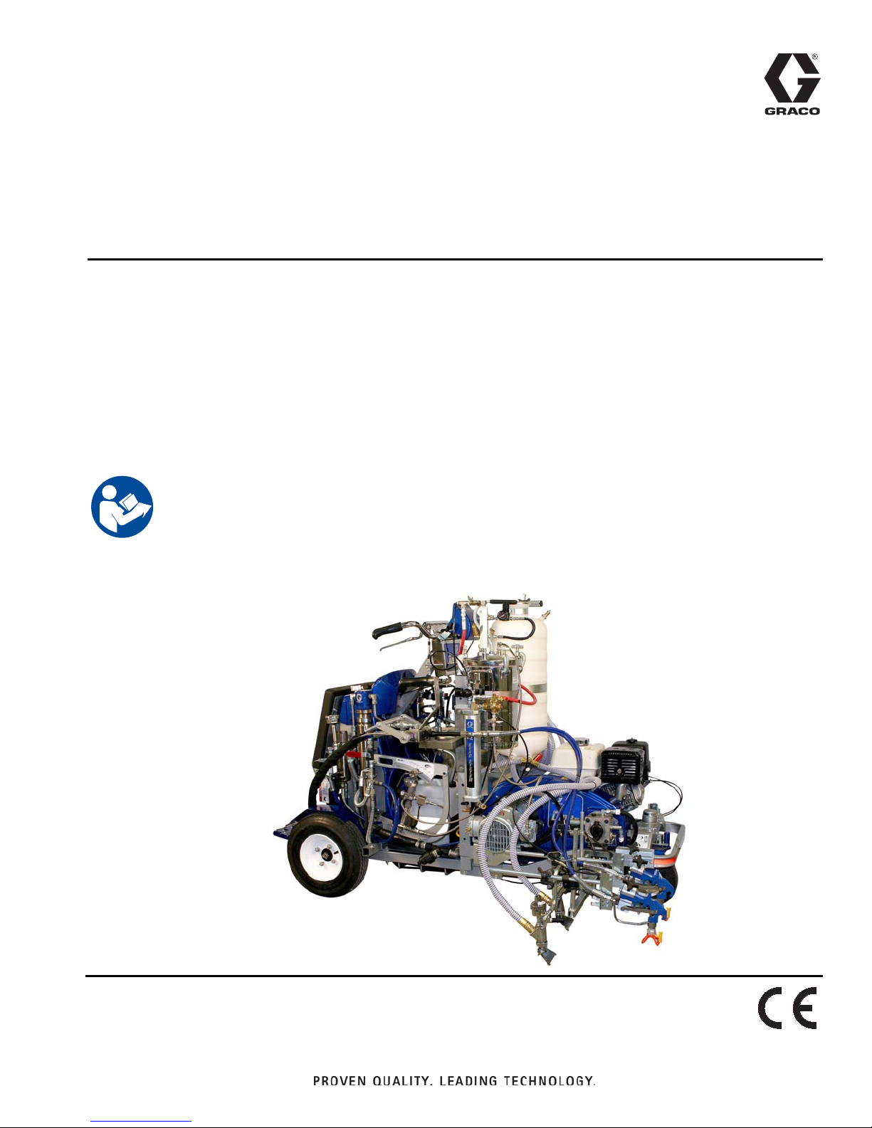
LineLazer IV 250MMA
Self-Propelled Line Striper
For the application of line striping materials.
For use with only Benox® L40LV liquid initiator BPO (B)
For professional use only.
For outdoor use only.
Not for use in hazardous locations or explosive atmospheres.
3A3111 A
EN
Maximum Operating Speed: 10 mph (16 kph)
Maximum Operating Pressure: 3000 psi (20.7 MPa, 207 bar)
Model 17G589
Important Safety Instructions
Read all warnings and instructions in this manual,
related manuals and the engine manual.
Be familiar with the controls and the proper usage of
the equipment. Save these instructions.
Related Manuals
LL IV 250 DC Operation 333388
Global Symbols 334224
LL IV 250 DC Repair 334053
LL IV 250 DC Parts 334054
Pressurized Bead System 332230
Bead Gun Kit 332226
Bead Gun 308612
Displacement Pump 309277
Airless Spray Gun 308491
2-Gallon Pressure Tank 308370
LL IV 250 DC Repair (French 334136
LL IV 250 DC Repair (Spanish 334137
Page 2

Contents
Important Benzoyl Peroxide (BPO) Information . . 6
Component Identification . . . . . . . . . . . . . . . . . . . . 7
Operation . . . . . . . . . . . . . . . . . . . . . . . . . . . . . . . . . 8
Pressure Relief Procedure . . . . . . . . . . . . . . . . . 8
Soft Key Message . . . . . . . . . . . . . . . . . . . . . . . . 8
Trigger Lock . . . . . . . . . . . . . . . . . . . . . . . . . . . . 8
Startup . . . . . . . . . . . . . . . . . . . . . . . . . . . . . . . . 9
Flushing Procedure . . . . . . . . . . . . . . . . . . . . . . . . 13
Cleanup . . . . . . . . . . . . . . . . . . . . . . . . . . . . . . . . . 15
Flush the Equipment . . . . . . . . . . . . . . . . . . . . . 15
MMA Smart Control Operation . . . . . . . . . . . . . . . 16
Menu Tree . . . . . . . . . . . . . . . . . . . . . . . . . . . . . 16
MMA/Epoxy Mode . . . . . . . . . . . . . . . . . . . . . . . 17
Flush Timer Setup . . . . . . . . . . . . . . . . . . . . . . . 17
17H095 Mix Manifold Parts . . . . . . . . . . . . . . . . . . 19
16P125 Slave Pump Linkage Parts . . . . . . . . . . . . 20
17H093 BPO Slave Pump Parts List . . . . . . . . . 22
17H093 Slave Pump Fittings . . . . . . . . . . . . . . . . . 23
Subassembly Items . . . . . . . . . . . . . . . . . . . . . . . . 24
Notes . . . . . . . . . . . . . . . . . . . . . . . . . . . . . . . . . . . . 25
Graco Standard Warranty . . . . . . . . . . . . . . . . . . . 26
2 3A3111 A
Page 3
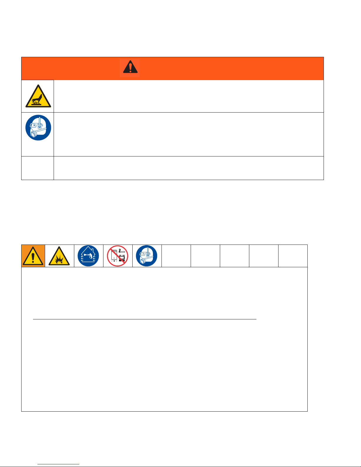
Warnings
Warnings
The following warnings are for the setup, use, grounding, maintenance, and repair of this equipment. The exclamation point symbol alerts you to a general warning and the hazard symbols refer to procedure-specific risks. When
these symbols appear in the body of this manual or on warning labels, refer back to these Warnings. Product-specific
hazard symbols and warnings not covered in this section may appear throughout the body of this manual where
applicable.
WARNING
TRAFFIC HAZARD
Being struck by other vehicles may result in serious injury or death.
• Do not operate in traffic.
• Use appropriate traffic control in all traffic areas.
• Follow local highway and transportation regulations for traffic control (for example: Manual on Uniform
Traffic Control Devices, U.S. Department of Transportation).
FIRE AND EXPLOSION HAZARD
Flammable fumes, such as solvent and paint fumes, in work area can ignite or explode. To help prevent fire
and explosion:
• Use equipment only in well ventilated area.
• Do not fill fuel tank while engine is running or hot; shut off engine and let it cool. Fuel is flammable
• and can ignite or explode if spilled on hot surface.
• Eliminate all ignition sources; such as pilot lights, cigarettes, portable electric lamps, and plastic drop
• cloths (potential static arc).
• Keep work area free of debris, including solvent, rags and gasoline.
• Do not plug or unplug power cords, or turn power or light switches on or off when flammable fumes
• are present.
• Ground all equipment in the work area. See Grounding instructions.
• Use only grounded hoses.
• Hold gun firmly to side of grounded pail when triggering into pail. Do not use pail liners unless they
• are antistatic or conductive.
• Stop operation immediately if static sparking occurs or you feel a shock. Do not use equipment
• until you identify and correct the problem.
• Keep a working fire extinguisher in the work area.
3A3111 A 3
Page 4
Warnings
WARNING
INJECTION HAZARD
High-pressure fluid from gun, hose leaks, or ruptured components will pierce skin. This may look like just a
cut, but it is a serious injury that can result in amputation. Get immediate surgical treatment.
• Do not spray without tip guard and trigger guard installed.
• Engage trigger lock when not spraying.
• Do not point gun at anyone or at any part of the body.
• Do not put your hand over the spray tip.
• Do not stop or deflect leaks with your hand, body, glove, or rag.
• Follow the Pressure Relief Procedure when you stop spraying and before cleaning, checking, or ser-
vicing equipment.
• Tighten all fluid connections before operating the equipment.
• Check hoses and couplings daily. Replace worn or damaged parts immediately.
CARBON MONOXIDE HAZARD
Exhaust contains poisonous carbon monoxide, which is colorless and odorless. Breathing carbon
monoxide can cause death.
• Do not operate in an enclosed area.
PRESSURIZED ALUMINUM PARTS HAZARD
Use of fluids that are incompatible with aluminum in pressurized equipment can cause serious chemical
reaction and equipment rupture. Failure to follow this warning can result in death, serious injury, or property
damage.
• Do not use 1,1,1-trichloroethane, methylene chloride, other halogenated hydrocarbon solvents or fluids
containing such solvents.
• Many other fluids may contain chemicals that can react with aluminum. Contact your material supplier
for compatibility.
ENTANGLEMENT HAZARD
Rotating parts can cause serious injury.
• Keep clear of moving parts.
• Do not operate equipment with protective guards or covers removed.
• Do not wear loose clothing, jewelry or long hair while operating equipment.
• Equipment can start without warning. Before checking, moving, or servicing equipment, follow the Pres-
sure Relief Procedure and disconnect all power sources.
4 3A3111 A
Page 5
Warnings
WARNING
MOVING PARTS HAZARD
Moving parts can pinch, cut or amputate fingers and other body parts.
• Keep clear of moving parts.
• Do not operate equipment with protective guards or covers removed.
• Do not wear loose clothing, jewelry or long hair while operating equipment.
• Equipment can start without warning. Before checking, moving, or servicing equipment, follow the Pres-
sure Relief Procedure and disconnect all power sources.
EQUIPMENT MISUSE HAZARD
Misuse can cause death or serious injury.
• Do not operate the unit when fatigued or under the influence of drugs or alcohol.
• Do not exceed the maximum working pressure or temperature rating of the lowest rated system compo-
nent. See Technical Data in all equipment manuals.
• Use fluids and solvents that are compatible with equipment wetted parts. See Technical Data in all
equipment manuals. Read fluid and solvent manufacturer’s warnings. For complete information about
your material, request MSDS from distributor or retailer.
• Do not leave the work area while equipment is energized or under pressure.
• Turn off all equipment and follow the Pressure Relief Procedure when equipment is not in use.
• Check equipment daily. Repair or replace worn or damaged parts immediately with genuine manufac-
turer’s replacement parts only.
• Do not alter or modify equipment. Alterations or modifications may void agency approvals and create
safety hazards.
• Make sure all equipment is rated and approved for the environment in which you are using it.
• Use equipment only for its intended purpose. Call your distributor for information.
• Route hoses and cables away from traffic areas, sharp edges, moving parts, and hot surfaces.
• Do not kink or over bend hoses or use hoses to pull equipment.
• Keep children and animals away from work area.
• Comply with all applicable safety regulations.
• Do not carry passengers.
• Check work area for reduced overhead clearance (e.g. doorways, tree branches, parking ramp ceilings)
and avoid contacting them.
BATTERY HAZARD
The battery may leak, explode, cause burns, or cause an explosion if mishandled. Contents of an open
battery can cause severe irritation and/or chemical burns. If on skin, wash with soap and water. If in eyes,
flush with water for at least 15 minutes and get immediate medical attention.
• Only use the battery type specified for use with the equipment. See Technical Data.
• Battery maintenance must only be performed or supervised by personnel knowledgeable of batteries
and the required precautions. Keep unauthorized personnel away from battery.
• Do not dispose of battery in fire. The battery is capable of exploding.
• Follow local ordinances and/or regulations for disposal.
• Do not open or mutilate the battery. Released electrolyte has been known to be harmful to the skin and
eyes and to be toxic.
• Remove watches, rings, or other metal objects.
• Only use tools with insulated handles. Do not lay tools or metal parts on top of battery.
3A3111 A 5
Page 6
Important Benzoyl Peroxide (BPO) Information
BURN HAZARD
Equipment surfaces and fluid that’s heated can become very hot during operation. To avoid severe burns:
• Do not touch hot fluid or equipment.
PERSONAL PROTECTIVE EQUIPMENT
Wear appropriate protective equipment when in the work area to help prevent serious injury, including eye
injury, hearing loss, inhalation of toxic fumes, and burns. This protective equipment includes but is not limited to:
• Protective eyewear, and hearing protection.
• Respirators, protective clothing, and gloves as recommended by the fluid and solvent manufacturer.
CALIFORNIA PROPOSITION 65
This product contains a chemical known to the State of California to cause cancer, birth defects or
other reproductive harm. Wash hands after handling.
WARNING
Important Benzoyl Peroxide (BPO) Information
BPO contains highly reactive (unstable) chemicals that produce the curing reaction of methacrylic resins. The highly
reactive property of BPO also produces hazards that require great care and caution in the handling, processing, storage, transportation and disposal of BPO.
BPO is flammable and potentially explosive when reacting to contamination by other materials or when
exposed to heat or heat build-up from contamination reactions. A contamination reaction can cause BPO to
reach its Self-Accelerating Decomposition Temperature (SADT). Reaction may start slowly, taking from seconds to days, gradually building up heat. This can produce an explosion. To help prevent fire and explosion:
• Read and understand the BPO manufacturer’s warnings and Safety Data Sheet (SDS) to know specific
hazards and precautions related to BPO.
• Prevent contamination of BPO with other materials (even small amounts), including but not limited to
diluents, polyester overspray, sanding dust, polymerization accelerators and promoters
metals. Keep work area clean and free of waste.
• Never return BPO to the original container.
• Remove spills promptly so no residues remain.
• Keep BPO away from heat, sparks and open flames.
• Never dilute BPO with acetone or any solvent. This can produce an extremely shock-sensitive compound
that can explode.
• Use only genuine manufacturer’s parts in the catalyst system (hoses, fittings, etc.). A reaction may result
between substituted parts and BPO.
• Store BPO in the original containers in a cool, dry and well-ventilated area away from direct sunlight and
away from other chemicals in accordance with BPO manufacturer’s recommendations.
• Do not store BPO for an extended period of time.
• To prevent contact with BPO, wear appropriate personal protective equipment, including chemically impermeable gloves, boots, aprons and goggles.
, and non-stainless
6 3A3111 A
Page 7
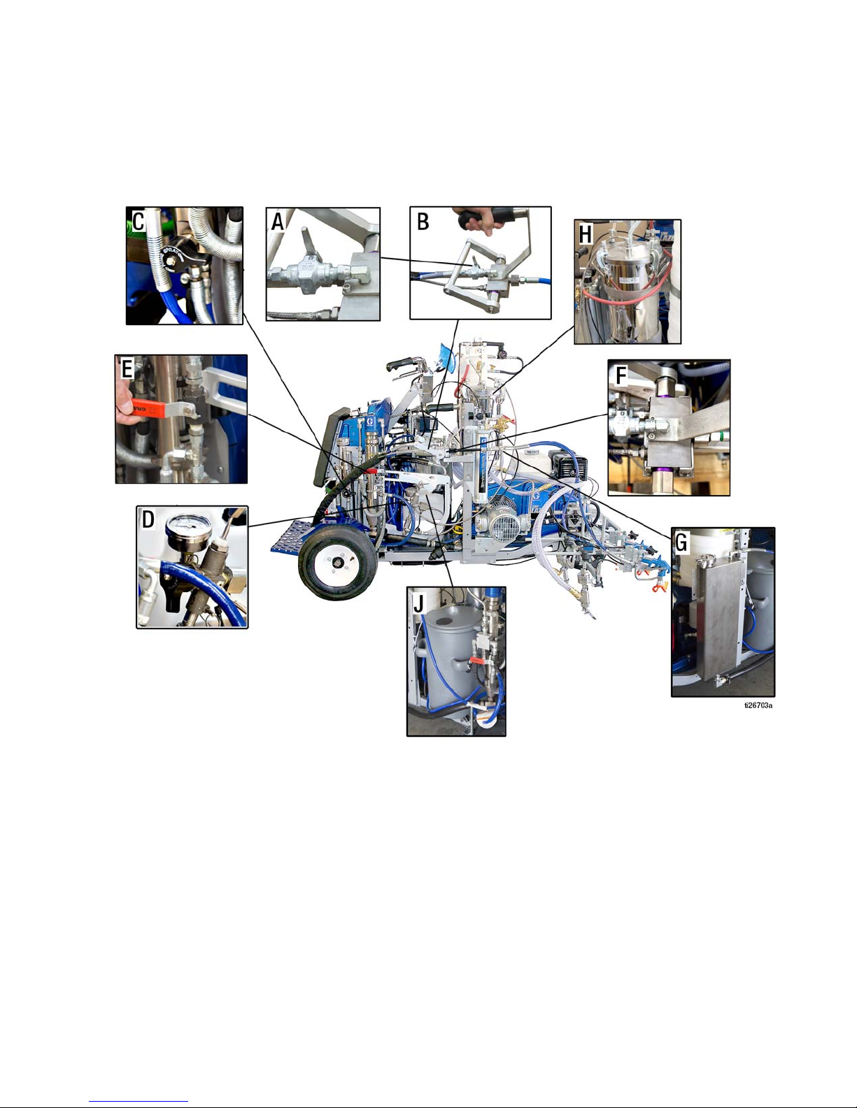
Component Identification
Component Identification
A Solvent Valve
B Material Supply Valve
C Resin Dump Valve
D Benzoylperoxide (BPO) Dump Valve
E Hydraulic Valve
For complete operation and parts information refer to the related manuals listed on the cover of this document. This
document provides the operation information required when spraying two part coatings.
3A3111 A 7
F Mix Manifold
G Solvent Tank
H BPO Pressure Pot
JResin Tank
Page 8
Operation
ti23144a
ti3441a
PAINT
ti3305a
ti3324a
ti6473a
ti26702a
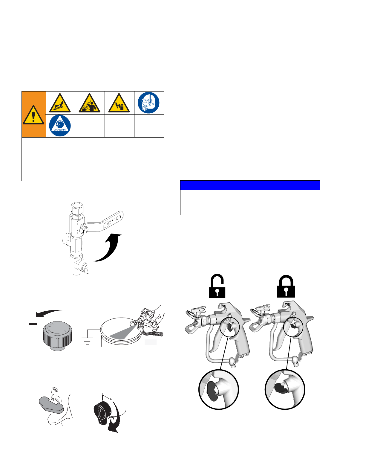
Operation
Pressure Relief Procedure
This equipment stays pressurized until pressure is
manually relieved. To help prevent serious injury
from pressurized fluid, such as skin injection, splashing fluid and moving parts, follow the Pressure Relief
Procedure when you stop spraying and before cleaning, checking, or servicing the equipment.
1. Set both (2) pump valves to OFF. Turn engine OFF.
4. Leave drain valve(s) open until you are ready to
spray again.
5. If you suspect the spray tip or hose is clogged or
that pressure has not been fully relieved:
a. VERY SLOWLY loosen the tip guard retaining
nut or the hose end coupling to relieve pressure
gradually.
b. Loosen the nut or the coupling completely.
c. Clear the obstruction in the hose or tip.
Soft Key Message
NOTICE
To prevent damage to soft key buttons, do not
press the buttons with sharp objects such as pens,
plastic cards, or fingernails.
Trigger Lock
Always engage the trigger lock when you stop spraying
to prevent the gun from being triggered accidentally by
hand or if dropped or bumped.
2. Turn pressure control to lowest setting. Trigger all
guns to relieve pressure.
3.
Engage all gun trigger locks. Turn both (2) prime
valves down.
8 3A3111 A
Page 9

Operation
Startup
For additional information refer to Operation manual (333388).
• Close solvent valve (A) on mix manifold
• Close material supply lever (B) on mix manifold
• Open resin dump valve (C)
• Close catalyst
(D)
• Prime catalyst
• Open hydraulic valve (E) slowly to build
1200-1500psi on catalyst (BPO)
• Close hydraulic valve (E)
• Close resin dump valve (C)
• Open hydraulic valve (E) to build pressure on Resin
(2000-2500psi)
• Open material supply lever (B) on mix manifold
• Reverse tip on the spray gun
Benzoylperoxide (BPO) dump valve
Benzoylperoxide (BPO) slave pump
2. Close material supply lever (B) on mix manifold.
3. Open resin dump valve (C).
• Press the gun trigger button until material is clear of
solvent
• Load complete
• Enable Ratio Assurance Monitor Alarms
1. Close solvent valve (A) on mix manifold.
4. Close catalyst (BPO) dump valve (D).
3A3111 A 9
Page 10

Operation
5. Prime catalyst BPO slave pump.
a. Make certain Dump Valve is closed.
b. Crack open the line fitting on the transducer
pressure manifold.
6. Fill tanks with resin (J), catalyst (H), and solvent (G).
7. Start the unit, see Setup/Startup in Operation manual (333388).
8. Verify tip and guard installation and check gun
placement. See Operation manual (333388) for
more information.
9. Open hydraulic valve (E) slowly to build
1200-1500psi on catalyst (BPO).
10. Close hydraulic valve (E).
c. Operate slave pump until fluid leaks out of the
fitting loosened in Step b.
d. Tighten the line fitting on the transducer pres-
sure manifold.
NOTICE
Always rinse any spilled BPO/Benox off unit with
soapy water and then rinse with water to prevent oxidation and decomposition.
10 3A3111 A
Page 11

Operation
ti26701a
11. Close resin dump valve (C).
12. Open hydraulic valve (E) to build pressure on Resin
(2000-2500psi).
13. Open material supply lever (B) on mix manifold.
14. Reverse tip on the spray gun.
a. Engage the trigger lock.
b. Rotate tip to the spray position.
3A3111 A 11
c. Disengage the trigger lock.
Page 12

Operation
15. Press the gun trigger button until material is clear of
solvent.
16. Startup is complete.
17. Enable Ratio Assurance Monitor Alarms. See MMA
Smart Control Operation, page 16.
12 3A3111 A
Page 13

Flushing Procedure
ti26702a
For additional information refer to Operation manual (333388).
• Close hydraulic valve (E)
• Reverse tip on spray gun
• Press the gun trigger button until pressure is gone
(below 500 psi)
• Close material supply lever (B) on mix manifold
• Check to see that you have the solvent pump on
• Open solvent valve (A) on mix manifold
• Press the gun trigger button until material is flushed
and solvent is clear
• Flushing is complete
1. Close hydraulic valve (E).
Flushing Procedure
2. Reverse tip on the spray gun.
a. Engage the trigger lock.
b. Rotate tip to the clean position.
ti26791a
3A3111 A 13
Page 14

Flushing Procedure
ti26789a
c. Disengage the trigger lock.
3. Press the gun trigger button until pressure is gone
(below 500 psi).
5. Check to see that you have the solvent pump on.
6. Open solvent valve (A) on mix manifold.
4. Close material supply lever (B) on mix manifold.
14 3A3111 A
7. Press the gun trigger button until material is flushed
and solvent is clear.
8. Flushing of catalyzed material is complete.
Page 15

Cleanup
Cleanup
For additional information refer to Operation manual (333388).
• Perform the Flushing Procedure, page 13
• Open dump valves on resin and Catalyst (BPO) (C
& D)
• Vent the resin and Catalyst (BPO) pressure pots
• Vent the air receiver to release any water
• End of day complete
Flush the Equipment
To avoid fire and explosion:
• Flush equipment only in a well-ventilated area
• Always ground equipment and waste container.
• To avoid static sparking and injury from splashing,
always flush at the lowest possible pressure.
1. Perform the Flushing Procedure, page 13.
2. Follow Pressure Relief Procedure, page 8.
3. Remove spray tip and soak in solvent.
4. Place siphon tube in grounded metal pail containing
cleaning fluid.
5. Set pump to lowest possible fluid pressure, and start
pump.
6. Hold a metal part of the gun firmly to a grounded
metal pail. Trigger the gun until clean solvent dispenses.
7. Remove gun from hose. See gun manual to further
clean gun.
8. Follow Pressure Relief Procedure, page 8, and
Remove fluid filter and soak in solvent. Replace filter cap.
9. Open dump valves on resin and Catalyst (BPO) (C
& D)
10. Vent the resin and Catalyst (BPO) pressure pots
11. Vent the air receiver to release any water
• Flush before changing colors, before fluid can dry in
the equipment, at the end of the day, before storing,
and before repairing equipment.
• Flush at the lowest pressure possible. Check connectors for leaks and tighten as necessary.
• Flush with a fluid that is compatible with the fluid
being dispensed and the equipment wetted parts.
NOTICE
Flushing: Flush BPO system with soapy water remove
water to avoid freeing. Dispose of used BPO per manufacturers recommendations.
Operating temperatures: Only use BPO at temperatures between 32–110°F (0–43°C). Never heat BPO
for any reason.
Shelf life: Use only within the manufacturers recommended shelf life. Discolored (yellowish), clumpy or
dries BPO is often out of date or contaminated. Store
BPO in a cool location.
3A3111 A 15
Page 16

MMA Smart Control Operation
MMA/EPOXY SOFTWARE SCREENS
ti26784a
MMA Smart Control Operation
Menu Tree
16 3A3111 A
Page 17

MMA/Epoxy Mode
10-40 5-20 15-30 5-10
PAINT 10.0’
SPACE 30.0’
- - - JOB MIL
0.0’
MMA
BPO
2500 psi
- - - - gallon s
2300 psi
0 mph
M
M/A
500 ȴ PSI
M/A
LOW PSI
00:47
E
1
43
346
5
5
2
1
2
ti26782a
MMA Smart Control Operation
Ref. Description
LOW PSI is flashed if either pressure is below the
1
user defined MIN PSI VALUE.
The progress bar will give a visual of the pressure
differential between the 2 pumps.
2
When the pressure differential is outside the user
defined value the progress bar will be filled and an
Error triangle will flash next to it.
Press the button to RESET
the Ratio Assur-
ance feature when it is enabled. The alarm will not
resume monitoring until the MIN PSI and the MAX
Δ PSI values are again satisfied by the system.
3
– Enabled and monitoring
– Enabled and not monitoring
– Disabled
4 Flush Timer indicates how much time is left on
the pot life of the mixed material in the hose. This
resets to the inputted value whenever a gun is
actuated/sprayed. Flush timer is NOT controlled
by pressing the button for activation and
deactivation.
5 After material Designation is selected to input what
material or ratio is being ran, this changes the title
above each pump. MMA 98:2 shows titles: MMA
(A) and BPO. The 1:1, 2:1, 3:1 and 4:1 (epoxies)
show titles: RESIN(A) and HARDENER(B).
Ref. Description
1 When the GUN SHUTOFF is enabled, the guns do
not fire or shut off when the pressure drops below
the MIN PSI VALUE set by the user or if the pressure differential is outside MAX Δ PSI value set by
the user.
2 When the ALARM BEEP is enabled, a beep
occurs once a second while the guns are fired if
the pressure drops below the MIN PSI VALUE set
by the user or if the pressure differential is outside
MAX Δ PSI value set by the user.
3 FLUSH TIMER allows the user to set a pot life
timer. This indicates to the user when the mixed
material in the hose has been sitting for the
inputted amount of time. A countdown is displayed
on the main screen and when the time reaches
zero the control will beep/flash indicating that the
user should flush the system. Flush Timer does
NOT count down if both pressures are below the
minimum setting.
4 MIN PSI VALUE is the minimum pressure allowed
for either pump. This is defined by the user. This
can be set between 0 – 2500 psi in 100 psi increments.
5 Material Designation is selected to input what
material or ratio is being ran. This will change the
title above each pump. MMA 98:2 shows titles:
MMA (A) and BPO. The 1:1, 2:1, 3:1 and 4:1
(epoxies) show titles: RESIN(A) and HARDENER(B).
6 MAX Δ PSI is the maximum pressure differential
allowed for the two pumps. This is defined by the
user. Can be set between 100 – 1000 psi in 50 psi
increments. This helps ensure proper ratio.
Flush Timer Setup
Flush mode is used to set the time period from when
spraying stops until the alarm notifies the operator that a
3A3111 A 17
flush is required to prevent material from setting up in
the unit.
Page 18

MMA Smart Control Operation
2
3
ti26785a
1
1. Use to select Ratio Assurance.
Ref. Description
1 Open Flush Timer Menu.
2 ENABLE or DISABLE alarm notification.
3 Number of minutes before alarm is displayed.
2. Press
to open Flush Timer Menu.
3. Set Flush Timer parameters.
18 3A3111 A
Page 19

17H095 Mix Manifold Parts
1
2
5
6
7
8
9
11
10
12
12
2
4
17H095 Mix Manifold Parts
ti26727a
17H095 Mix Manifold Parts List
Ref. Part Description Qty.
1 124859 BOLT, shoulder, 1/4-20 x 5/16 2
2 262808 KIT, valve relief 2
3 112309 NUT, hex, jam 2
4 16E334 HANDLE, manifold 2
5TBD
Endisys
6 248875 VALVE, ball, with lever 1
7 501684 VALVE, check 1
8 215619 VALVE, check 1
HANDLE, grip 1
3A3111 A 19
Ref. Part Description Qty.
9 215618 VALVE, check 2
10 TBD
Endisys
11 TBD
Endisys
12 NA BODY, manifold, Not sold sepa-
13 17H095 MIX MANIFOLD, complete 1
O-ring 1
INJECTOR, fluid 1
rately
Page 20

16P125 Slave Pump Linkage Parts
1
2
3
9
5
6
7
8
16P125 Slave Pump Linkage Parts
4
Ref. Part Description Qty.
1 16N776 KIT, upper link, slave 1
2 16N775 KIT, lower link, slave 1
3 119999 BOLT, shoulder 2
4 116969 NUT, lock 1
5 7486-05 WASHER, flat, standard #10 1
ti26739a
Ref. Part Description Qty.
6 7486-03 WASHER, flat, fender 1/4 1
7 24M092 PIN, quick release, 1.5 x 0.25 1
8 111040 NUT, lock, nylock, 5/16 1
9 120476 BOLT, shoulder, 5/16 1
10 16P125 HARNESS, slave linkage assembly 1
Replacement Danger and Warning labels, tags, and
17H093 BPO Slave Pump Parts
20 3A3111 A
Page 21

WLD
926
910
902
902d
902b
902f
902a
902e
902f
902g
901
946
935
909
909
907
932
947
904
911
912
913
908
914
915
916
917
918
919
920
919
920
925
923
921
922
924
932
947
946
947
External Mix Only
924
930
936
940
940
945
903
903a
903b
903c
1
1
1
1
11
1
11
3
1 15
1
1
1
5
6
9 10
8
7
8
6
6
1
6
1
1
1
14
13
1
1
5
3
12
1
4
Apply pipe sealant to threads.
Apply thread locker to mating surfaces or threads.
Apply grease to mating surfaces or threads.
Torque to 240 in-lb (27.1 N•m).
Torque to 225-275 in-lb (25.4-31.1 N•m).
Loop large end of lanyard over gauge prior to
assembling gauge. Attach small end of lanyard to
split ring on pin.
Note orientation of u-cup.
Torque to 30-50 in-lb (3.4-5.6 N•m).
Clean cylinder inner diameter with soft cloth or
equivalent, prior to assembly.
Hand tighten cylinder (918) and bottom out to
housing (901). Back-off cylinder (918) less than 1/2
turn. Assembly pin (908).
Press fit bearings.
Torque piston rod (910) to top link (926) to
80-100 in-lb (9.0-11.3 N•m).
Torque to 20 - 60 in-lb (2.3-6.8 N•m).
Snap 902e onto 902a.
Orient so inside chamfer of nipple (936) is mated to
swivel (930).
1
2
3456789
101112
13
14
15
16P125 Slave Pump Linkage Parts
3A3111 A 21
Page 22

16P125 Slave Pump Linkage Parts
17H093 BPO Slave Pump Parts List
Ref. Part Description
901 --- HOUSING, slave pump 1
902 24C479 KIT, cartridge, FRP 1
902a --- CARTRIDGE, slave pump 1
902b†
902d†
902e
902f
902g
903 16N975 VALVE, 3000 psi blow off (also
903a 224807 BASE, valve 1
903b 15C780 HANDLE 1
903c 15C972 PIN, spring 1
904 17H096 KIT, repair, drain valve 1
907 113641 GAUGE, pressure, fluid 1
908 123595 PIN, quick release 1
909 124193 CABLE, lanyard, 5 inch 1
910 16N964 ROD, piston, slave pump (also
911
912
913
914 16K960 HOUSING, transfer, etched 1
915
916
917 16A666 CAP, transfer housing 1
918 --- CYLINDER, slave pump 1
919‡
920‡
921 LPA-144 NUT, lock 1
922 16N976 HOUSING, inlet, slave 1
923‡
924 --- BEARING, flanged, 0.375 ID 2
925
926 16N617 KIT, repair, catalyst pump yoke 1
930 114339 FITTING, union, swivel, 1/4 npt 1
932 123628 FITTING, adapter, 1/8 npt - #4 jic 1
935 110208 PLUG, pipe, headless 1
936 94/0320-1/98 FITTING, nipple, 1/4; series D
940 24U857 VALVE, ball, mini; not used on
945 16V703 FITTING, 1/4 npt x 3/8 tube, sst 1
946 16V704 FITTING, 1/8 npt x 1/4 tube, 90,
947 16V705 FITTING, 1/8 npt x 1/4 tube, sst 1
--- BEARING, cartridge 1
--- WIPER, felt, piston rod 1
16P186 SEAL, snap on, cartridge 1
16A981 SEAL, slave pump weep 2
123556 O-RING, silicone #016 1
includes 903a, 903b, and 903c)
includes 919, 920, and tool
16D007)
123636 SPRING, transfer housing 1
16K928 VALVE, poppet 1
123934 O-RING, 003, FKM 1
LPA-126 SEAL, radial 1
LPA-127 GUIDE, piston 1
CJ-143 O-RING, o-ring, silicone, 2-014 2
124061 RING, backup, 0.518 ID,
0.053 wide
--- SEAT, ball, 7/16 dia. 1
LPA-134-02 BALL, spherical 1
only
series D
080803 VALVE, ball, 1/4 npt, ff, 316 sst;
series D only
sst
Qty.
Installation Tools (not shown):
Foot valve seat installation tool, 16N966
Foot valve seat deluxe removal tool, 24N253 (includes
foot valve seat installation tool, 16N996)
Weep seal installation tool, 16N967
Rod Assembly Bullet Installation Tool, 16D007
1
--- Not for sale.
† Parts available in bearing and wiper repair kit
16P185.
‡ Parts available in foot valve repair kit 16N961.
Parts available in piston valve repair kit 16N962.
Parts and tools available in throat seal repair kit
16N963.
1
Complete rebuild kit 16N919 includes:
-Foot valve repair kit 16N961
-Piston valve repair kit 16N962
-Throat seal repair kit 16N963
-Foot ball replacement kit LPA-134-02
-Bearing with felt wiper 16P185
2
1
1
1
1
22 3A3111 A
Page 23

17H093 Slave Pump Fittings
17H093 Slave Pump Fittings
Ref. Part Description Qty.
1 17H096 KIT, repair, drain valve 1
2 TBD HOSE 1
3 17H093 KIT, repair, pump, slave complete 1
3A3111 A 23
Ref. Part Description Qty.
4 16N617 KIT, repair, catalyst, yoke 1
5 113641 GAUGE, pressure, fluid 1
6 16G410 MANIFOLD, pressure, transducer 1
7TBD HOSE 1
8 15F782 HARNESS, transducer 1
Page 24

Subassembly Items
Subassembly Items
Ref. Part Description Qty.
1 236155 TANK, low pressure 1
2 16M652 TANK, solvent, assembly 1
3 241705 GUN, spray 1
24 3A3111 A
Page 25

Notes
Notes
3A3111 A 25
Page 26

Graco Standard Warranty
Graco warrants all equipment referenced in this document which is manufactured by Graco and bearing its name to be free from defects in
material and workmanship on the date of sale to the original purchaser for use. With the exception of any special, extended, or limited warranty
published by Graco, Graco will, for a period of twelve months from the date of sale, repair or replace any part of the equipment determined by
Graco to be defective. This warranty applies only when the equipment is installed, operated and maintained in accordance with Graco’s written
recommendations.
This warranty does not cover, and Graco shall not be liable for general wear and tear, or any malfunction, damage or wear caused by faulty
installation, misapplication, abrasion, corrosion, inadequate or improper maintenance, negligence, accident, tampering, or substitution of
non-Graco component parts. Nor shall Graco be liable for malfunction, damage or wear caused by the incompatibility of Graco equipment with
structures, accessories, equipment or materials not supplied by Graco, or the improper design, manufacture, installation, operation or
maintenance of structures, accessories, equipment or materials not supplied by Graco.
This warranty is conditioned upon the prepaid return of the equipment claimed to be defective to an authorized Graco distributor for verification of
the claimed defect. If the claimed defect is verified, Graco will repair or replace free of charge any defective parts. The equipment will be returned
to the original purchaser transportation prepaid. If inspection of the equipment does not disclose any defect in material or workmanship, repairs
will be made at a reasonable charge, which charges may include the costs of parts, labor, and transportation.
THIS WARRANTY IS EXCLUSIVE, AND IS IN LIEU OF ANY OTHER WARRANTIES, EXPRESS OR IMPLIED, INCLUDING BUT NOT
LIMITED TO WARRANTY OF MERCHANTABILITY OR WARRANTY OF FITNESS FOR A PARTICULAR PURPOSE.
Graco’s sole obligation and buyer’s sole remedy for any breach of warranty shall be as set forth above. The buyer agrees that no other remedy
(including, but not limited to, incidental or consequential damages for lost profits, lost sales, injury to person or property, or any other incidental or
consequential loss) shall be available. Any action for breach of warranty must be brought within two (2) years of the date of sale.
GRACO MAKES NO WARRANTY, AND DISCLAIMS ALL IMPLIED WARRANTIES OF MERCHANTABILITY AND FITNESS FOR A
PARTICULAR PURPOSE, IN CONNECTION WITH ACCESSORIES, EQUIPMENT, MATERIALS OR COMPONENTS SOLD BUT NOT
MANUFACTURED BY GRACO. These items sold, but not manufactured by Graco (such as electric motors, switches, hose, etc.), are subject to
the warranty, if any, of their manufacturer. Graco will provide purchaser with reasonable assistance in making any claim for breach of these
warranties.
In no event will Graco be liable for indirect, incidental, special or consequential damages resulting from Graco supplying equipment hereunder, or
the furnishing, performance, or use of any products or other goods sold hereto, whether due to a breach of contract, breach of warranty, the
negligence of Graco, or otherwise.
Graco Information
For the latest information about Graco products, visit www.graco.com.
For patent information, see www.graco.com/patents.
TO PLACE AN ORDER, contact your Graco distributor or call 1-800-690-2894 to identify the nearest distributor.
All written and visual data contained in this document reflects the latest product information available at the time of publication.
GRACO INC. AND SUBSIDIARIES • P.O. BOX 1441 • MINNEAPOLIS MN 55440-1441 • USA
Copyright 2015, Graco Inc. All Graco manufacturing locations are registered to ISO 9001.
Graco reserves the right to make changes at any time without notice.
Original instructions. This manual contains English. MM 3A3111
Graco Headquarters: Minneapolis
International Offices: Belgium, China, Japan, Korea
www.graco.com
Revision A,
July 2015
 Loading...