

Page 1

Starlite 2
Operating Instructions - 15390
Page 2

1
Preparation……………………………………….
1.1
Battery………………………………………………
7
1.2
Self-test…………………………………………….
7
1.3
Selecting the function groups:
DIP switches in the battery compartment……….
8
2
Display panel
2.1
The display panel and its elements……………...
9
2.2
Display duration…………………………………….
10
2.3
Key Lock…………………………………………….
10
3
Operating elements
3.1
ISO1 - IS02; selecting the film speed……………
11
3.2
Menu………………………………………………...
12
3.3
Setting wheel……………………………………….
12
3.4
Measuring buttons M and AVR
12
3.5
Measuring head with optical viewfinder 1 ° or 5°
Flat dome- spherical dome……..…………………
13
4
This is how the Starlite 2 works
4.1
Incident and reflected light measuring…………..
14
5
Meas. functions - Ambient light
5.1
Aperture priority…………………………………….
16
5.2
Exposure time priority……………………………..
17
5.3
Exposure value EV………………………………...
17
5.4
Contrast measuring in the t and EV functions…..
18
5.5
Averaging value AVR in the t and EV functions..
19
5.6
Selecting the exposure time values……………...
20
5.7
Taking measurements in the zone system……...
21
6
Measuring functions- Flash light
6.1
Flash light measuring……………………………..
23
6.2
Flash calculation for changed meas. times….…
24
6.3
Multiple flash calculation………………………….
24
6.4
Average value……………………………………...
25
7
Taking a measuring outside the
measuring range - display range
7.1
Taking a measurem. outside the meas. range…
26
7.2
Taking a measurement outside the display
range………………………………………………..
26
8
Setting and measuring correction values
and extension factors
8.1
Setting correction values………………………….
27
9
CINE meter for cinematographers PHOTOMETRY
9.1
Preselecting the Cine speeds……………………
29
9.2
Taking measurements in the CINE function……
29
9.3
Setting the shutter angle………………………….
30
10
Photometry
10.1
Selecting the Photometry display unit…………..
31
10.2
Meas. the Illumination Lux (Ix) or footcandle (fc)
31
10.3
Measuring the luminance candela/m² (cd/m²)
or footLambert (fL)………………………………..
32
10.4
Measuring time-integral values
(lxs, fcs, cds/m2, fLs)……………….……………..
33
11
Practical tips………………………………………
34
12
Technical data…………………………………….
37
13
Service Interface…………………………………
39
14
Service……………………………………………..
39
2 Gossen Foto- und Lichtmesstechnik GmbH
Page 3

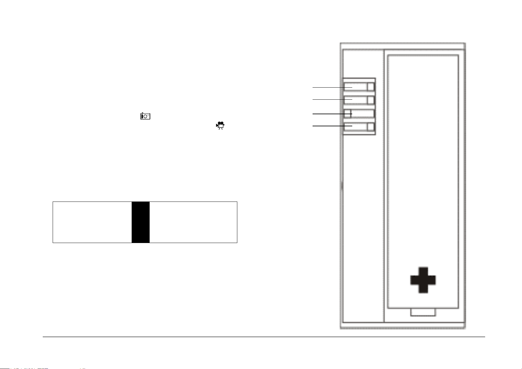
3
Measuring head
with optical viewfinder
Display panel
Description
on page 9
ISO1 button
ISO2 button
Socket for
the flash sync cord
Menu buttons
Retractable dome
Dome ring for setting of
reflected/incident light measuring
Reflected light measuring 1°
Reflected light measuring 5°
Incident light measuring,
flat dome
Incident light measuring,
spherical dome
Gossen Foto- und Lichtmesstechnik GmbH
Page 4

Optical viewfinder
Measuring button M
Setting wheel
Measuring button AVR
Eyelet
Serviceinterface
4 Gossen Foto- und Lichtmesstechnik GmbH
Page 5

5
DIP Switches
Battery
Battery
Serial number
Gossen Foto- und Lichtmesstechnik GmbH
Page 6

Your STARLITE 2 is the top device in the GOSSEN
product range and represents a real all-in-one light
meter. It combines a light meter for ambient and flash
light, a CINE meter for cinematographers as well as a
measuring Instrument for lighting technology and
photometry. And the clarity of the operating control
elements and the digital display is still preserved.
Functions used over and above the normal metering
can be individually integrated by the user.
The STARLITE 2 can be easily converted into a
complete CINE meter for the cinematographer and
their needs.
Due to the microprocessor technology, the user
benefits from our knowledge on lighting technology
which we have gained over decades of experience in
the construction of light meters.
As a result of its precise calibration, the STARLITE 2
provides very accurate measuring results and is easy
to operate.
Characterising of the STARLITE 2:
- Splashwaterproof housing
- Digital stop display in 1/10 stop increments
- Automatic display Illumination
- Shutter Speeds in full or 1/2 time values
- Second ISO value
- Incident light measuring with spherical/flat dome
- Reflected light measuring, option of 1° or 5°
- Flash measuring (cord/cordless)
- Display of the ambient light portion
- Flash calculation with different measuring times
- Flash calculation for multiple flashes
- Analogue contrast display
with f/stops in 1/2 stop increments
- Averaging of up to 9 measuring values
- Storage of settings and measuring values
- Configurable EV correction
- Measuring in accordance with the zone system
- Direct display of the measuring values on the
zone scale
- Special CINE meter, settable for shutter angles
other than 180 degrees, conversion with
formulas is not necessary
- Functional range of photometry
Measuring of illuminance
and luminance with ambient and flash light
- Key lock
6 Gossen Foto- und Lichtmesstechnik GmbH
Page 7

7
1 Preparation
1.1 Battery
The STARLITE 2 works with a 1.5 V AA battery
(Alkaline-manganese.
When the battery is running low, the BAT display
appears in addition to the measured values as a
warning to the user.
At this stage, it is advisable to replace the battery as
soon as possible.
When BAT appears on the display alone,
measurements can no longer be taken.
Replace the battery immediately.
To replace the battery, open the battery compartment
of the STARLITE 2, remove the old battery and insert
the new one. Observe the "+" and "-" polarity! Please
close the cover of the battery compartment.
1.2 Self-test
After the new battery has been inserted, the microcomputer will carry out a self-test. Here, every display
segment of the display panel appears. The self-test
takes about 10 s. It can, however, be interrupted
before by pressing any button.
As soon as the self-test is complete, the factory preset
standard settings are activated.
ISO1 100/21° 0/1,0
ISO2 50/18°
f 5,6 t 1/125
EV 12 Blitz f 1/60
f/s 24
Warning!
Do not view and do not aim the meter directly
at the sun.
You may not only damage your eye, but also ruin the
light-sensitive cell.
Gossen Foto- und Lichtmesstechnik GmbH
Page 8
1.3 Selecting the function groups:
Zone System
fc fl
1/2 t-Steps
CINE
4
-
lx cd/m²
1/1 t-Steps
STILL
3
2
1
DIP 4
DIP 3
DIP 2
DIP 1
In addition to the standard functions, your STARLITE 2
features a range of additional characteristics and
functions which can be selected using the
"DIP switches" in the battery compartment.
- DIP 1 Selection STILL – Photography
CINE und PHOTOMETRY
- DIP 2 Selection SHUTTER SPEEDS (1/1 or 1/2)
- DIP 3 Selection DISPLAY UNIT photometry
- DIP 4 Selection Measuring function - ZONES
DIP switches in the battery compartment
8 Gossen Foto- und Lichtmesstechnik GmbH
Page 9

9
2 Display panel
6 1 7 2 13 3 8 4 9 5 10
14 12 15 12 16 1718 11
2.1 The display panel and ist elements
1 Menu
- Ambient light
- Flash light
2 Measuring head
- Incident light measuring
- Reflected light measuring
3 Meter functions
- Photography
- Cine / Photometry
4 Film speed ISO1 - ISO2
5 Digital display of the film speed
6 Display signal f - EV
7 Display signal Zone
8 Display signal – Function correction value
9 Display signal t – f/s
10 Battery check warning signal
11 Display signal second (s) – minutes (m)
12 Display signal AVR u. M (memory)
13 Display signal photometry
- Illuminance (lx – fc)
- Luminance (cd/m2 – fL)
- Time integral values
( lx*s – fc*s – cd/m2 *s – fc*s)
14 Analogue scale
15 left digital displays for
- f-stop (f)
- Exposure value (EV)
- Correction values
- Multiple flash calculation
- Average (f) – Number of measurings
- Zone
- Ready for flash (F)
- Photometric measuring values
16 Right digital display for
- Exposure time (t)
- Extension factor – correction value
- Flash calculation, number of flashes
- Cine speeds (f/s)
17 Zone scale
18 Aperture scale
Gossen Foto- und Lichtmesstechnik GmbH
Page 10

2.1.1 Automatic display illumination
When the lighting conditions are poor (about EV 4 or
less), the background lighting of the display is switched
on automatically for 10 seconds.
2.2 Display duration
If the STARLITE 2 display panel is idle for about
2 minutes, it is switched off automatically. The
measuring values and the preset values remain
stored in memory.
- By pressing anyone of the buttons, you can recall
the measuring value from the memory.
- By pressing the measuring button M, a new
measurement is taken.
The measuring values of the last measurement remain
stored in the memory until a new measurement is
taken.
The STARLITE 2 has separate memories for ambient
and flash light measuring.
2.3. Key Lock
lt makes sense to activate the key lock to avoid
switching on the STARLITE 2 by accident.
- Activating the key lock: press
ISO1 and IS02 simultaneously.
OFF, ISO and IS02 appear for 3 seconds on the
display. Then the instrument switches off
automatically.
If you press any button, OFF, ISO and IS02 are
displayed again for 3 seconds.
- Deactivating the key lock:
press ISO1 and IS02 simultaneously.
10 Gossen Foto- und Lichtmesstechnik GmbH
Page 11

11
3 Operating elements
3.1 ISO - IS02
Selecting the film speed
You can select two different film speeds with the
ISO1 and IS02 buttons.
- Select the film speed by pressing and holding
"ISO1" or "IS02". ISO or IS02 will flash on the
display panel.
- Set the desired ISO value using the setting wheel.
When another operating function is selected,
the preset film speed is retained in the STARLITE 2
memory.
The film speed you have selected, either ISO1 or IS02,
appears in the top right corner of the display panel (IS02
as long as the IS02 button is pressed).
When the IS02 button is pressed, the converted
shutter speed/f-stop values are displayed on the basis
of the last measuring. Therefore, you no longer have to
carry out time consuming calculations when working
with 2 films of different speeds.
If the film speed is changed, the last measuring value
is converted to the new ISO settings. The selected film
speed is memorized until it is changed in accordance
with the above mentioned procedure.
Gossen Foto- und Lichtmesstechnik GmbH
Page 12

3.2 Menu
Menu-
Buttons
Setting wheel
Button AVR
With the function buttons you can select the measuring
modes ambient light or flash light an.
Keep the menu button pressed and select the subfunctions time preselection t, f-number preselection f
or exposure value EV using the setting wheel.
3.3 Setting wheel
The setting wheel allows you to change values and
functions.
- Presetting for ambient, flash and ISO
- Calling up shutter speed/f-stop combinations after
measuring. Multiple flash calculation
- Allocation of zones
- Selection of shutter angles in the CINE function
3.4 Measuring buttons – M and AVR
With the measuring button M you can trigger off a new
measurement and delete all previous measuring
values.
The measuring button AVR is used for calculation
average values.
12 Gossen Foto- und Lichtmesstechnik GmbH
Page 13

13
3.5 Measuring head with optical viewfinder 1°or5°
Reflected light
measuring 1°
Reflected light
measuring 5°
Incident light measuring,
spherical dome
Dome ring
Incident light measuring,
flat dome
Flat dome- spherical dome
The measuring head is the optical control center of the
STARLITE 2. The 270° rotating measuring head
provides the basis for effective working in practice.
Caution:
Never try to overwind the built-in lock by force.
Sooner or later this will cause the connection
between measuring head and basic meter to break
and will have to be repaired!
The following measuring modes can be selected
using the diffuser ring at the measuring head
- Reflected light measuring 1°, spot measuring
- Reflected light measuring 5°, selective measurement
- Incident light measuring, flat dome
- Incident light measuring, spherical dome
The optical viewfinder with measuring angles of 1 ° and
5° for reflected light measuring is also located in the
measuring head. Due to these measuring angles it is
possible to precisely focus an even the smallest spots in
the subject.
The viewing field is about 12°.
Gossen Foto- und Lichtmesstechnik GmbH
Page 14

4. Incident and reflected light measuring
Your STARLITE 2 is designed for the enthusiastic
amateur as well as for professional use.
Its rotating measuring head is the optical "control center",
and the following measuring functions can be set:
- Incident light measuring, dome raised:
spherical measuring characteristics
- Incident light measuring, dome lowered:
flat measuring characteristics
- Reflected light measuring with 5° measuring angle
through the viewfinder
- Reflected light measuring with 1 ° measuring angle
through the viewfinder
Thus, the meter can be conveniently used for all
measuring methods including the zone system.
4.1.1 Incident light – Spherical dome
Set "dome raised" with the dome ring at the measuring
head. The symbol appears on the display.
Taking measurements using the incident light method
in parti cular can produces perfectly exposed shots.
With the incident light mode, the STARLITE 2
measures with its dome the incident light from the
subject towards the camera.
This guarantees that the tone quality of the picture is
equivalent to that of the subject. This is especially
important for very bright or dark subjects.
Even under very difficult photographing conditions, as
for example with subjects which have a lot of contrast,
the incident light measuring method is a much more
reliable way of producing well-exposed and
professional pictures.
4.1.2 Incident light – Flat dome
The lowered/retracted dome having a flat
characteristic is suitable for reproductions and
for taking measurements for special lighting technology
and photometry.
For this function, the "dome lowered" with the
dome ring at the measuring head must be set.
14 Gossen Foto- und Lichtmesstechnik GmbH
Page 15

15
4.1.3 Reflected light – 1° Spot measuring
For this function, the setting ring at the base of the dome
must be set to the "Reflected light - 1° Symbol. The
symbol appears on the display. In the viewfinder, the
measured area corresponds to the inner, smaller
circle.
Your STARLITE 2 offers reflected light measuring with
1°(spot measuring) via the viewfinder in the measuring
head. When you look through the viewfinder, you can
measure using the measuring buttons M and AVR from
the camera towards the object. This way, even the
details of a subject can be accurately measured and
analysed through the viewfinder. Now, only the light
reflected from the subject is detected.
When using the reflected light mode, the measuring
values always depend on the reflection of the subject!
As a result of this, bright subjects are reproduced darker
and are therefore not properly exposed.
If the exposure measurement is carried out in
accordance with the reflected light measuring method,
it is advantageous to use a grey chart (18% diffuse
reflection). Furthermore, you can also be given the
average values of up to 9 measuring values. The
different contrast measuring values are displayed on
the analogue aperture scale. Subject contrast is
measured with the reflected light measuring method
and displayed by the STARLITE 2 on the analogue
scale.
4.1.4 Reflected light – 5° Selective measurement
For this function, the "Reflected light measurement 5°"
must be set with the dome ring at the measuring head.
The symbol appears on the display.
In the viewfinder, the measuring area corresponds to
the outer, wider circle.
The functions and notes of chapter 4.1.3, page 15 also
apply here.
Gossen Foto- und Lichtmesstechnik GmbH
Page 16

5 Measuring functions – Ambient light
- Select with the left menu button ambient
light (the last stored measuring value
appears in the display).
- Keep the function button pressed down and
select the corresponding sub-function using the
setting wheel. This function is displayed in a
frame .
- Set the desired value using the setting wheel
alone.
5.1 Aperture priority
- Press the measuring button M to take a
measurement.
- The measured exposure time t appears on the right
digital display. The f-number is automatically adjusted
to the time measured in 1/10 stop increments.
Furthermore, the f-number, which is rounded to 1/2
stop increments, is displayed as a mark on the
analogue scale.
- Other shutter speed/f-stop combinations can be
selected using the setting wheel.
Note:
When preselecting f-stop, the stored values
of the last measurement are displayed in 1/10 stop
increments. These are, however, irrelevant, since a
new reading has to be taken.
16 Gossen Foto- und Lichtmesstechnik GmbH
Page 17

17
5.2 Exposure time priority
- Press the measuring button M to take a
measurement.
- The measured f/stop appears on the left digital
display (resolution in 1/10 stop increments) and is
marked an the analogue scale, rounded to 1/2 stop
increments.
- Select other paired f/stop-exposure time values with
the setting wheel.
- Instead of the full exposure time values, also ½
time values can be set by activating DIP switch 2.
5.3 Exposure value
- Press the button M to measure.
- The measured exposure value EV appears on
the left digital display (resolution in 1/10 stop
increments) and the f/stop is marked additionally
on the analogue scale rounded to 1/2 stops.
- Select other paired f/stop-exposure time values with
the setting wheel.
Gossen Foto- und Lichtmesstechnik GmbH
Page 18

5.4 Contrast measuring
in the t and EV functions
Contrast of the subject reflected light
measuring through the viewfinder
- Keep the measuring button M pressed
and focus on the various areas of the subject to be
measured.
- The first measuring value appears on the left digital
display. It is constantly displayed as a reference value
(e.g. measurement on a grey chart) during the course
of the entire measuring process. The actual
measuring value flashes on the analogue scale.
- After releasing the measuring button M, the
measured subject contrast range appears on the
analogue scale.
Illumination contrast
with flat or spherical dome
- Keep the measuring button M pressed to measure
the different light sources.
- The first measuring value appears an the left digital
display. It is constantly displayed as a reference
value (e.g. main light source) during the course of the
entire measuring process. The actual measuring
value flashes on the analogue scale.
- After you release the measuring button M, the total
illumination contrast measured appears on the
analogue scale.
18 Gossen Foto- und Lichtmesstechnik GmbH
Page 19

19
5.5 Averaging value AVR in the t and EV
functions Reflected light measuring
through the viewfinder
- The first measurement is to be taken with the
measuring button M.
- With the average measuring button AVR you can
measure up to 8 further contrast spots.
The single measuring values are displayed on the
analogue scale (identical measuring values are only
displayed once, but are taken into consideration when
the averaqe is calculated). After each measurement
with AVR, the average of all previous measuring
values is displayed. The average AVR appears on
the left digital display: f or EV with f-numbers in 1/10
increments and flashing on the analogue scale,
rounded to 1/2 stop increments. In the middle of the
display, the number of measurements M is displayed
(4 measurements in the example).
Incident light
with flat or spherical dome
Correspondingly, you can determine the average value
of the illumination of the various lights with the above
mentioned procedure. To do this, you can measure for
example your main, fill-in and background light
individually in the Studio.
Gossen Foto- und Lichtmesstechnik GmbH
Page 20

5.6 Selecting the exposure time values
DIP 2
In addition to the standard full time values, also half
time values (1/2 TV) can be set at some cameras.
For this reason, the STARLITE 2 can also be set
additionally to half time values.
The selection is made activating the DIP 2 switch:
- 1/1 full time values
Exposure times are displayed in 1/1 full time values
or when using the CINE function, in the standard
CINE film speeds.
- 1/2 half time values
Exposure times are displayed in 1/2 half time values.
With this function, additional CINE speeds are
displayed.
20 Gossen Foto- und Lichtmesstechnik GmbH
Page 21

21
5.7 Taking measurements in the zone system
This function is mainly used to cope with subject
contrasts.
In addition to the influence of Illumination, there is a
further possibility of optimizing the contrast range in
the workflow.
The zone system allows details to be reproduced in
the picture which otherwise would not be visible and
would be lost. A detailed analysis of this technique
would, however, go beyond the scope of these
instructions.
5.7.1 The STARLITE 2 and the zone system
The STARLITE 2 allocates different brightness ranges
to predefined graduated zones of grey. Variations of
these grey topes from the middle zone determine the
exposure correction and the changes in the digital
workflow.
Taking measurements in the zone system
For using the zone system activate the switch
DIP 4 in the battery compartment.
- Set the dome ring at the measuring head to the
“reflected light - 1 °".
- Keep the left menu button pressed and select the
sub-function ZONE using the setting wheel.
- Using the viewfinder, focus on the spot of the subject,
which should still be shown up in the motif.
- Press the measuring button M. The meas. value will
then be automatically allocated to zone V.
Gossen Foto- und Lichtmesstechnik GmbH
- Using the setting wheel, place the measuring value in
the zone where the value should be, e.g. zone III.
- Now you can measure up to 8 further spots in the
subject using the measuring button AVR - the most
important brightest spot, which should still show detail
in the subject, must be included.
Page 22

After each measurement using the measuring button
AVR the following data are stored and displayed:
- the symbol ZONE and the last measured value are
displayed on the left
- the number of measurements made are displayed
on the right (4 measurements in the example)
- on the zone scale the currently measured
values are indicated (identical values only
once) and the average of the brightest and
the darkest spot as a flashing dot
When the measuring process is completed and you
then switch over to the “ambient light” function and
the desired measuring function, the value measured
in the zone V is displayed as shutter speed/f-stop
combination. Additionally, the flashing ZONE symbol is
displayed.
Now, you can select further shutter speed/f-stop
combinations using the setting wheel.
lf, by mistake, you take a zone measurement in the
incident light mode (flat or spherical diffuser), you are
reminded by the flashing diffusor symbol
that you have to set the diffuser ring to 1 ° spot
metering.
Black and white photography
Note down the subject contrast for the film
development and adjust the development time in
accordance with the contrast range.
22 Gossen Foto- und Lichtmesstechnik GmbH
Page 23

23
6 Measuring functions- Flash light
In essence, flash measuring can be carried out
in all diffuser settings (incident or reflected light
measuring modes). Furthermore, flashes can be
measured with or without a sync cord (cord/noncord). If
a sync cord is used, the flash is automatically triggered
and measured with the measuring button M.
6.1 Flash light measuring
- Select the menu using the right menu button
(the last stored measuring value appears).
- The function is displayed with .
- Set the desired measuring time (sync speed) using
the setting wheel. The measuring times range from
1 s to 1/1000 s. Press the measuring button M. The
STARLITE 2 is ready to measure for about 45 s (as
long as F is displayed on the display panel).
- Trigger flash
When using a sync cord, the flash is triggered and
measured automatically when pressing M.
- The measured f-number (sum of flash light and
ambient light) appears both in the left digital display
(resolution 1/10 stops) and as a flashing indicator in
the analogue scale rounded to the nearest
1/2 f-number.
In addition to this, the f-stop for the share of the
ambient light is displayed on the analogue scale, not
flashing.
Gossen Foto- und Lichtmesstechnik GmbH
Page 24

6.2 Flash calculation
for changed measuring times
If the measurement shows that the ambient light part in
relation to the flash light part does not correspond to
your wishes in the overall lighting, the STARLITE 2
calculates on the basis of the measurement taken the
influence of altered measuring times.
Other measuring times can be set directly using the
setting wheel without taking another measurement. The
calculation of the new result appears directly on the
display.
Note:
In the event of altered measuring times, you must
ensure that the flash light duration is not longer
than the preselected measuring time. If this is the
case, a new measurement must be taken.
6.3 Multiple flash calculation
Occasionally, the light output from a single flash may
not be sufficient to enable you to work at the aperture
desired. In that case, you can preselect the desired
f-stop. Keep the right function button depressed and
select with the setting wheel the sub-function .
Release the menu button and select the desired
f-stop.
The STARLITE 2 calculates on the basis of the
measurement already taken the number of flashes
required for the desired f-stop. The digital display of the
time disappears and the number of flashes required is
indicated, (e.g. F4 = 4 flashes) The STARLITE 2 will
calculate up to a max. of 9 flash sequences.
24 Gossen Foto- und Lichtmesstechnik GmbH
Page 25

25
6.4 Average value
- Take first measurement using measuring button M
- Messure up to a further 8 flashes using the
average value measuring button AVR .
The individual measurements are shown an the
analogue scale (identical values are only displayed
once, but are taken into account in the calculation of
the average value).
After each measurement with AVR , the average
value of all previous measurements is always
displayed. The average value AVR is shown in the
digital display:
at the left with fine adjustment in 1/10 stop
increments and shown as a flashing mark in the
analogue scale, rounded to the nearest 1/2 f-stop.
However, the ambient light portion is not indicated.
In the centre of the display, the number of
measurements M taken is indicated (in the example
4 measurements).
Gossen Foto- und Lichtmesstechnik GmbH
Page 26

7 Taking a measuring outside the
measuring range - display range
7.1 Taking a measurement
outside the measuring range
- There is no usable measuring result outside the
measuring range of the STARLITE 2.
- If it is too dark or too bright during the measurement,
Err (= Error) appears in the left digital display.
7.2 Taking a measurement
outside the display range
If the symbol uu or nn appears in the right or left digital
display, the measurement has been taken but the result
is outside the display range.
- Use setting wheel to move into the display range
26 Gossen Foto- und Lichtmesstechnik GmbH
Page 27

27
8 Setting and measuring correction values
and extension factors
8.1 Setting correction values
- By simultaneously pressing both menu buttons
and
you reach the function - correction values.
- The last valid correction value appears in the
display.
- The desired correction value can be entered or
altered using the setting wheel.
The extension factor is shown in the right digital display,
and the correction value is indicated in stops. Input in
1/10 EV (small digits) in the range of ±9.9 exposure value
stop increments.
For correction values which extend the exposure a ” -"
appears in front of the number.
Example:
-3.1 stops correspond to the extension factor 8.6.
For corrections which shorten the exposure, only the
left display appears as EV difference in stop
increments. By pressing one of the menu buttons
( or ) the correction value is stored in the memory of
the STARLITE 2. The symbol appears in the
display.
The correction value is automatically taken into account
in all measuring functions (except for the photometry).
Gossen Foto- und Lichtmesstechnik GmbH
Page 28

8.1.1 Measuring correction values
Correction values can also be measured directly.
An evenly illuminated surface and constant light level
are required.
Use the STARLITE 2 in the reflected light mode at
1 ° or 5°.
In the function , a reference measurement can be
taken by pressing the measuring button M.
Designation rF - - in the digital display.
Then, hold the filter in front of the viewfinder and press
the measuring button AVR.
The light reducing effect will be indicated automatically in
the display as EV stop and extension factor.
8.1.2 Deleting correction values
In the function - correction values (chapter 8.1,
page 27) you have two possibilities of deleting preprogrammed correction values:
- by manually resetting using the setting wheel to
EV 0 and extension factor 1.0 or
- by pressing the measuring button M
(display rF - -)
- quit the correction value function using the
menu button ( or )
Correction value is deleted.
Symbol has disappeared from the display.
28 Gossen Foto- und Lichtmesstechnik GmbH
Page 29

29
9 CINE meter for cinematographers
- PHOTOMETRY
By actuating the DIP 1 switch, the STARLITE 2 can be
converted easily and quickly into a fully functional
CINE meter. At the same time switch on the function
photometry.
CINE metere
- Select reflected light or incident light mode at the
measuring head.
- Using the left button, press menu ambient light .
9.1 Preselecting the Cine speeds
- Press and hold the left menu button and
using the setting wheel set the speed “f/s”.
The function is shown in the display as
- Set the desired CINE speed using the setting
wheel.
- Contrast (chapter 5.4, page 18) and average
value measurements (chapter 5.5, page 19)
can also be carried out.
Using the switch DIP 2 additional CINE speeds
can be switched on.
9.2 Taking measurements in the CINE function
- Take a measurement by pressing the measuring
button M
- The measured f-stop appears both in the left digital
display (resolution 1/10 stop increments) and as an
indicator in the analogue aperture scale rounded to
the nearest 1/2 f-stop.
Gossen Foto- und Lichtmesstechnik GmbH
Page 30

9.3 Setting the shutter angle
The shutter angle in the STARLITE 2 is preset at the
factory to 180°.
If you are working with other angles which vary from
the shutter angle 180°, you can enter these directly.
Therefore, no need for lengthy calculation.
- Simultaneously press both menu buttons ( and ).
The current angle appears in the right display.
- Set the required angle in 5° stop increments using the
setting wheel.
- By pressing a menu button ( or ) you move
back into the measuring function. The selected angle
is shown in the display with the symbol .
A shutter angle other than 180° has a direct influence
on all measuring functions in the CINE function;
corrected measuring values are shown directly in the
display.
These angle correction values do not influence the
measuring results in the photometry function.
Unlike in the photo functions, correction entries
cannot be made here.
30 Gossen Foto- und Lichtmesstechnik GmbH
Page 31

31
10 Photometry
10.1 Selecting the photometric display unit
Use the DIP1 switch to change over to the functions
CINE/Photometry. With the DIP 3 switch, you can select
either the standardized measuring units or special
ones used in certain English speaking countries.
- Ix, cd/m2: the photometric incident measurement
values are displayed in the standardised units
(Ix, Ixs, cd/m2, cds/m2).
- fc, fl: the photometric incident measurement values
are displayed in Anglican measuring units
(fc, fcs, fL, fLs). This means the values do not have
to be converted.
- Press and hold the left menu button and select
the sub-functions illumination or luminance using
the setting wheel.
Depending on the DIP 3 switch setting, lx or fc will
appear in the display.
10.2 Measuring the illumination
Lux (Ix) or footcandle (fc)
- Set the measuring head to incident light measuring
- flat diffuser.
When setting the dome at the measuring head
to spherical, an error indication will appear
(flashing ).
- Aim the measuring head in the direction of the
illumination source.
- Take a measurement using the measuring button M.
Gossen Foto- und Lichtmesstechnik GmbH
Page 32

10.3 Measuring the luminance
candela / m2 (cd/m2) or footLambert (fL)
- Set the measuring head to reflected light measuring
1° or 5° . The luminance function is set and
shown in the display.
- Focus on the subject to be measured via the
viewfinder
- Take a measurement using the measuring button M
The selected display unit and measured luminance
are displayed.
10.4 Measuring time-integral values
(Ixs, fcs, cds/m2, fLs)
- Set measuring head to reflected light or incident light
measuring. The corresponding display unit is set and
shown in the display.
- Set with the right menu button the function
flash light .
- Pre-select the desired measuring time using
the setting wheel; this can be found on the right hand
side of the display panel. Activated half time stop
increments are also displayed.
- Start flash measuring using the measuring button M
Cord/noncord (chapter 6.1, page 23).
- The measured value, which is calculated to
1 second, is shown in the pre-selected display unit.
By preselecting the measuring time, the ambient
light part is correspondingly taken into account.
32 Gossen Foto- und Lichtmesstechnik GmbH
Page 33

33
11 Practical Tips
Programming Influencing Quantities
Your STARLITE 2 ascertains precise exposure data in
accordance with DIN 19010. In the event that you’re
not satisfied with the results, keep in mind that there
are related influencing quantities which may effect
how well your image recordings turn out, for example:
“Actual” film speed may differ.
Your camera’s “actual” shutter speeds may deviate
somewhat from the nominal values.
Your camera’s “actual” f-stops may differ from those
specified.
Deviations may occur while developing negatives and
prints.
And all of this is compounded by subjective factors
and personal taste when evaluating finished pictures.
However, you can adapt your STARLITE 2 to your
camera’s individual characteristics, your workflow and
your own subjective evaluation criteria.
We recommend the following method: Carefully
measure several standard objects (gray charts, gray
step wedges and color charts are very well suited to
this end) after performing object and incident light
measurement, and complete a series of exposures for
each using the value ascertained by your STARLITE
2. The first image is recorded with the exposure value
displayed by the STARLITE 2. This exposure value is
increased or reduced by up to one f-stop for the
following images, depending upon lens resolution.
Lighting conditions must remain unchanged during
recording of all images. Pick out the best image from
the developed or printed pictures according to your
taste, and compare its data with the measurements. If
images recorded with a changed value look better to
you, you can program the corresponding value into
your STARLITE 2 with the help of the correction
values function (see section 8.1 on page 27).
Gossen Foto- und Lichtmesstechnik GmbH
Page 34

Contrast and Ideal Exposure
The basic rules for ideal exposure specify that the
brightest and darkest parts of the image must show
adequate detail. Personal taste and creative artistic
intent may, of course, render these rules null and void.
Thus only general recommendations can be provided
regarding the subject of ideal exposure.
It’s important to consider the fact that the final product
(photo, print etc.) is only capable of processing a small
contrast range in comparison with the human eye.
With the STARLITE 2, you can determine lighting
contrast with the incident light measurement method
and object contrast with the object measurement
method. In both cases, contrast is shown at the analog
display.
It usually isn’t possible to determine correct exposure
for your motif by measuring the brightest and darkest
points. These should be either a medium gray within
the motif, or the mean value of the measurement
results for the brightest and darkest points. The mean
value is calculated automatically by the STARLITE 2.
If you make sure that object contrast is greater than
your workflow is capable of processing, you can
brighten up shadows, for example with a brightening
screen or a flash, and thus reduce object contrast.
When object contrast is taken into consideration by
means of mean value generation, the following rules
of thumb apply:
Negative Film
If two steps (exposure values) are not exceeded
between bright and dark areas which are important for
the image, each intermediate value could basically be
used as a setting value (the mean value is more
appropriate for more exacting demands). This
produces a usable picture in most cases.
Denser negatives result in reduced definition.
In the case of negative film, the lowest, but
nevertheless still printable density is important, and it’s
thus better to overexpose a bit rather than to
underexpose.
Digital Photography – Color Transparency Film
In comparison with negative film, color transparency
film is capable of managing greater object contrast,
but its practically useful exposure latitude is
significantly smaller.
Measurement of object contrast is the basis for
deciding whether or not the motif can be reproduced
realistically. If the motif necessitates nothing further,
it’s advisable to measure against the lights.
In the case of color transparency film, the important
bright parts of the image are most significant. Keep
this in mind, and remember that it’s better to
underexpose a bit rather than to overexpose. In this
way, the colors appear more luminous and rich.
34 Gossen Foto- und Lichtmesstechnik GmbH
Page 35

35
Nighttime Atmosphere
If you want to accurately capture a nighttime
atmosphere with a lot of darkness and very little detail,
it’s best to use less exposure time than indicated by
your STARLITE 2, in order to assure that the image
doesn’t look like a daytime recording. There are no
fixed rules in this case. In order to gain experience,
start with image recordings for which you can use the
values displayed at the STARLITE 2 without changing
them.
In the Snow
Due to the surrounding snow-covered landscape,
object measurement will generally result in too little
exposure. Portions of the motif which are important for
the image would be underexposed due to the
extraordinarily high reflectivity of snow. In order to
adjust the measurement, record the image at plus 1 to
1½ exposure values.
However, incident light measurement is the better
solution. It provides correct measurement results in a
direct fashion. If you want to include special effects,
for example emphasize fine nuances in shadows
within the snow, subtract roughly ½ of a step from the
adjusted value.
You can measure any photographic scene correctly
with the STARLITE 2. Don’t forget that too much may
be demanded of the film itself in the event of
extremely high object contrast.
The Zone System
Use of the zone system allows the photographer to
evaluate differing brightness within the motif from an
exposure standpoint such that (adapted to the output
medium) an adequate tonal range and sufficient detail
are present, even in bright and dark areas within the
motif.
The measurement results obtained with the light meter
correspond to the mean gray tone (18% reflection) in
the zone V tone scale. Thanks to consistent
application of the definitions for the individual zones,
the STARLITE 2 is capable of allocating the measured
value to a given zone specified by the photographer.
This value, ascertained with zone 5, is set in the
defined zones depending upon the effect to be
achieved in the output medium.
In actual practice, for well know reasons, the digital
photographer looks for this first measured value in the
brightest part of the motif which still shows adequate
detail.
This eliminates exposure uncertainty to a great extent,
because with the system, the photographer is able to
visually plan the final results in advance before each
image is recorded.
Gossen Foto- und Lichtmesstechnik GmbH
Page 36

Definitions According to Ansel Adams
Shadow zones
I Nearly black:
blackening without detail,
noticeable differences to zone 0
II Gray-black:
insinuated detail,
very dark shadows, black clothing,
black textiles,
dark pine forest in shadows
III Very dark gray:
shadows with detail,
forest in sunlight, moist earth
Medium gray tones
IV Dark gray:
dark foliage and grass, stone, woodwork,
shadow zones in portraits,
sky with red filter
V Neutral gray or medium gray:
grey tones with 18% reflection,
gray chart, average detail in wood,
stone, dark skin colors
VI Light gray:
light skin color, bright blue sky,
light colored stone,
shadows on snow with sunlight
Bright zones
VII Very light gray,
very light skin colors,
bright textiles, snow with light from the side
VIII White with detail,
brightest parts of the motif which still show detail,
snow with detail,
highlights on skin,
IX White without detail,
polished surfaces,
snow with sunlight from the front
36 Gossen Foto- und Lichtmesstechnik GmbH
Page 37

37
12 Technical data
Measuring capabilities
Incident light measuring
(option of flat or spherical dome)
Reflected light measuring,
(measuring angle 1°or 5°, viewing field ca. 12°)
Analogue and digital display
Contrast measuring
Average value calculation
(from up to 9 measuring values)
Flash light measuring (Cord/Noncord)
Display of ambient light portion
Multiple flash calculation
Zone system
CINE Meter (preset shutter angle 180°,
other angles adjustable in 5° steps)
Photometry (illumination, luminance,
flash power and luminance)
Light sensor
2 Sbc silicon photo diodes, color-corrected
Shortest measurement distance
approx. 100 cm
Measuring range of ambient light (at ISO 100/21°')
Incident EV -2.5 to +18
Reflected 1° EV 2.0 to +18
Reflected 5° EV 0 to +18
Measuring range, at flash light (for ISO 100/21°)
Incident f/1.0 to f1128
Reflected 1° f/2.8 to f/128
Reflected 5° f/1.4 to f/128
Measued value processing
digital
Repeatability
±1 digit (= 0.1 EV)
Film speeds
ISO 3/6° to ISO 8000/40° (in 1/3 steps)
Apertures
f/0.5 to f/128
Shutter speeds
Standard speeds: 1/8000 s to 60 min
adjustable additionally:
s: 1/6000, 1/3000, 1/1500, 1/750, 1/350,
1/180, 1/90, 1/45, 1/20, 1/10, 1/6, 1/3, 1/0,
7, 1.5, 3, 6, 10, 20, 45
m: 1.5, 3, 6, 10, 20, 45
Flash measuring times (sync speeds) 1 s to 1/1000 s
Flash calculation for altered measuring times
1 s to 1/1000 s
Multiple flash calculation
up to 9 flashes
Gossen Foto- und Lichtmesstechnik GmbH
Page 38

CINE speeds
Standard values:
8,12,16,18, 24, 25, 30, 32, 50, 64
adjustable additionally:
2, 3, 4, 6, 36, 40, 48, 60, 72, 96, 120, 128, 150,
200, 240, 255, 300, 360
Other measuring ranges and display values in
Ix, fc, cd/m², fL, lxs, fcs, cds/m², fLs
Other displays
Meas. function, range over and range under
Included accessories
Case, strap, battery Instruction manual
Brief operating instructions
Operating temperature range
-10°C to +50°C
Storage temperature range
-20°C to +60°C
Humidity
IP class 54, water-splash resistant
(for measuring and display), battery check
Analogue scale
f/1.0 to f/128, zone 0 to X
Correction values/extension factors
EV -9.9 to +9.9 / EF 1.0 to 955
Key lock
Battery
1.5 V (AA)
Battery life
For over 5000 measurings with alkaline-mangan
batteries, with an assumed flash measurement
proportion of 30 % and activated display
illumination of 3 %
Dimensions
approx. 16.4 x 66 x 26 mm
Weight without battery
approx. 195 g
Illumination
0.5 to 199900 Ix; 0.05 to 50000 fc
Luminance
0.2 to 30000 cd/m2; 0.05 to 9000 fL
Flash illumination
2 to 30000 Ixs; 0.2 to 3000 fc*s
Flash luminance
0.3 to 1800 cds/m2; 0.1 to 500 fLs
38 Gossen Foto- und Lichtmesstechnik GmbH
Page 39

39
13 Service Interface
The STARLITE 2 has a built-in serial port on the
outside of the housing. The devices are calibrated at
the factory via this interface.
14 Service
No special maintenance is required, if the STARLITE
2 is handled correctly. Keep the outside surface
clean. Use a slightly dampened cloth for cleaning.
Do not use cleansers, abrasives or solvents.
Should the meter nevertheless not work to your
satisfaction, please send the STARLITE 2 to:
GOSSEN Foto- und Lichtmesstechnik GmbH
Lina-Ammon-Str.22
D-90471 Nürnberg I Germany
Telefon: +49 911 8602-181
Fax: +49 911 8602-142
E-Mail: info@gossen-photo.de
or to the GOSSEN distributor in your country. You
can find the address of the local GOSSEN distributor
on our website under www.gossen-photo.de.
Gossen Foto- und Lichtmesstechnik GmbH
Page 40

Printed in Germany – 15390 – 2/08.14
Subject to change without notice
GOSSEN Foto- und Lichtmesstechnik GmbH
Lina-Ammon-Str.22
D-90471 Nürnberg I Germany
Telefon: +49 911 8602-181
Fax: +49 911 8602-142
E-Mail: info@gossen-photo.de
www.gossen-photo.de
40 Gossen Foto- und Lichtmesstechnik GmbH
 Loading...