

Page 1
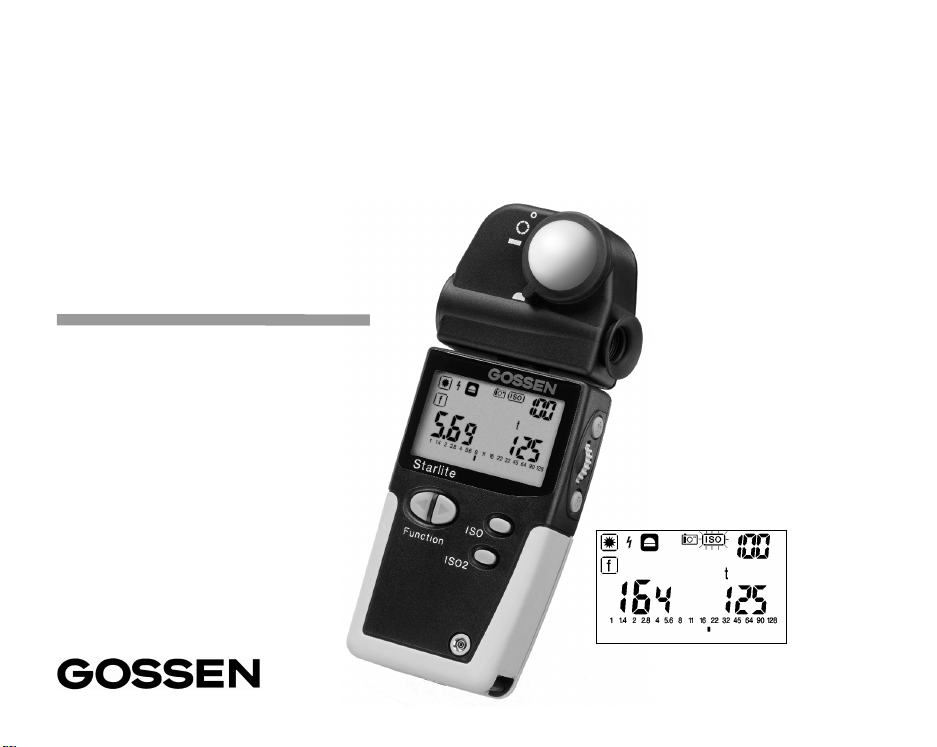
Starlite
All-in-one
Operating Instructions
Page 2
1 Preparation ............................................... 7
1.1 Battery ............................................................ 7
1.2 Self-test .... ...... ..... ...... ... ..... ...... ...... .. ...... ...... .... 7
1.3 Selecting the function groups:
DIP switches in the battery compartment ....... 8
2 Display panel ................. ...........................9
2.1 The display panel and its elements ................ 9
2.2 Display duration ............................................ 10
2.3 Key Lock .. ... ... ................... ... .................... ..... 10
3 Operating elements ........................... .... 11
3.1 ISO – ISO2; selecting the film speed ............11
3.2 Function .............................................. 12
3.3 Setting wheel ...... .................... ... ................... 12
3.4 Measuring buttons
3.5 Measuring head with optical viewfinder 1° or 5°
Flat diffuser– spherical diffuser ..................... 13
and ...................... 12
4 This is how the Starlite works ............... 14
4.1 Incident an d reflected light measuring .......... 14
5 Meas. functions – Ambient light ..... 16
5.1 Aperture prior it y ............................ ........... 16
5.2 Exposure time priority ............................ 17
5.3 Exposure value EV ........................................ 17
5.4 Contras t measuring
in the t and EV functions ............................... 18
5.5 Averaging value AVR
in the t and EV functions ............................... 19
5.6 Selecting the exposure time values .............. 20
5.7 Taking measurements in the zone system ... 21
6 Measuring functions– Flash light ... 23
6.1 Flash light measuring .............................. 23
2 GOSSEN Foto- und Lichtmeßtechnik
6.2 Flash calculation for changed meas. times ...24
6.3 Multiple flash calculation ................................24
6.4 Average value ................................................25
7 Taking a measuring outside the
measuring range – display range .........26
7.1 Taking a measurem. outside the meas. range ..26
7.2 Taking a measurement
outside the display range ...............................26
8 Setting and measuring correction values
and extension factors ............................27
8.1 Setting correction values ...............................27
9 CINE meter for cinematographers –
PHOTOMETRY ........................................29
9.1 Preselecting the Cine speeds ..................29
9.2 Taking measurements in the CINE function .29
9.3 Setting the shutter angle ................................30
10 Photometry .............................................31
10.1 Selecting the photometric display unit ...........31
10.2 Meas. the illumination Lux (lx)
or footcandle (fc) ............................................31
10.3 Measuring the luminance candela / m
or footLambert (fL) .........................................32
10.4 Measuring time-integral values
(lxs, fcs, cds/m
2
, fLs) .....................................32
2
(cd/m2)
11 Practical tips ...........................................33
12 Contrast and optimal exposure .............34
13 Technical data ........................................37
14 Serial interface ........................................39
15 Service .....................................................39
Page 3
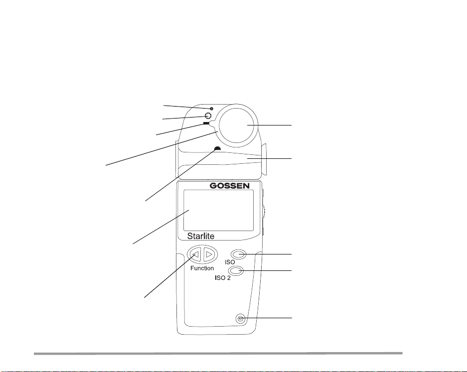
Reflected light measuring 1°
Reflected light measuring 5°
Incident light measuring,
flat diffuser
Diffuser ring
for setting of
reflected/incident light measuring
Incident light measuring,
spherical diffuser
Retractable diffuser
Measuring head
with optical viewfinder
Display panel
Description
on page 9
ISO button
ISO 2 button
Function buttons
Socket for
the flash sync cord
GOSSEN Foto- und Lichtmeßtechnik 3
Page 4
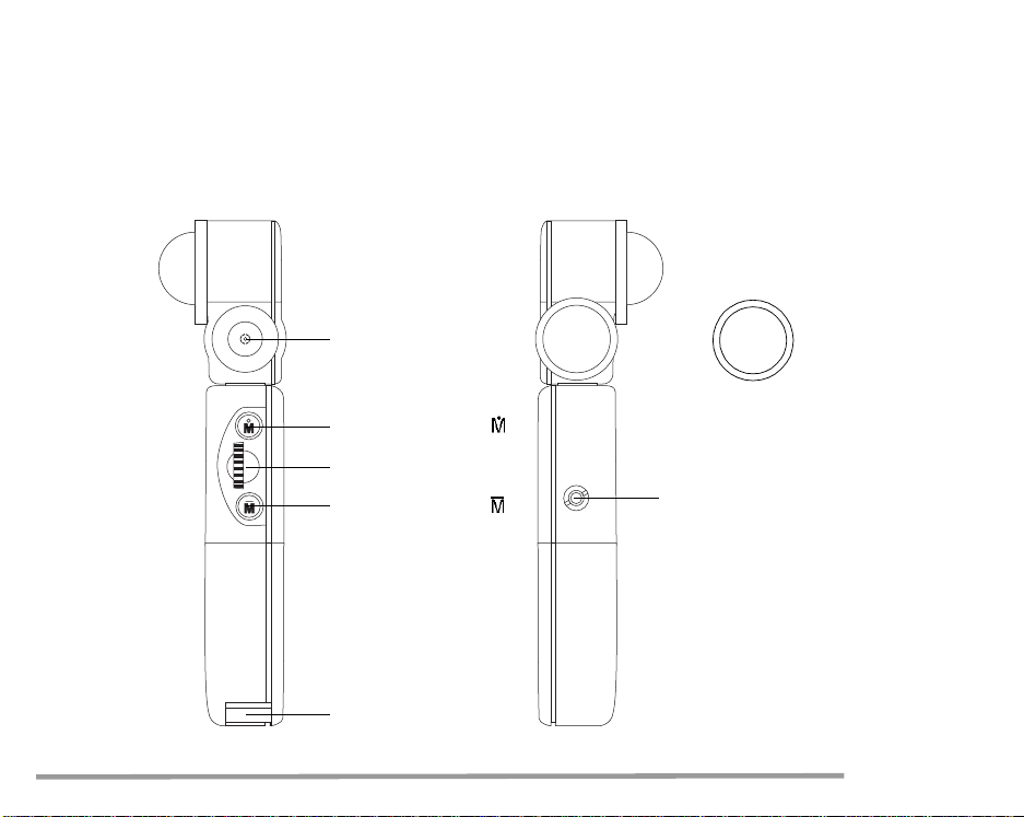
Optical viewfinder
Lens cover
Measuring button
Setting wheel
Measuring button
Serial interface
Eyelet
for connection cord
4 GOSSEN Foto- und Lichtmeßtechnik
Page 5
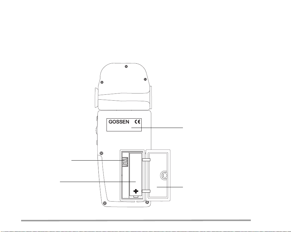
DIP switches
Serial number
Battery
Battery
compartment cover
GOSSEN Foto- und Lichtmeßtechnik 5
Page 6

Your Starlite is the top device in the GOSSEN-
product range and represents a real all-in-one light
meter. It combines a light meter for ambient and
flash light, a CINE meter for cinematographers as
well as a measuring instrument for lighting technology and photometry. And the clarity of the operating control elements and the digital display is still
preserved. Functions used over and above the
normal metering can be individually integrated by
the user.
The Starlite can be easily converted into a complete CINE meter for the cinematographer and
their needs.
Due to the microprocessor technology, the user
benefits from our knowledge on lighting technology
which we have gained over decades of experience
in the construction of light meters.
As a result of its precise calibration, the Starlite
provides very accurate measuring results and is
easy to operate.
Characterising of the Starlite:
– Splashwaterproof housing
– Digital stop display in 1/10 stop increments
– Automatic display illumination
6 GOSSEN Foto- und Lichtmeßtechnik
– Shutter speeds in full or 1/2 time values
– Second ISO value
– Incident light measuring
with spherical/flat diffuser
– Reflected light measuring, option of 1° or 5°
– Flash measuring (cord/cordless)
Display of the ambient light portion
Flash calculation with different measuring times
Flash calculation for multiple flashes
– Analogue contrast display
with f/stops in 1/2 stop increments
– Averaging of up to 9 measuring values
– Storage of settings and measuring values
– Configurable EV correction
– Measuring in accordance with the zone system.
Direct display of the measuring values on the
zone scale
– Special CINE meter, settable for shutter angles
other than180 degrees, conversion
with formulas is not necessary
– Funtional range of photometry
Measuring of illuminance
and luminance with ambient and flash light
– Key lock
Page 7
1 Preparation
1.1 Battery
The Starlite works with a 1.5 V AA battery
(Alkaline-manganese or corresponding
rechargeable battery).
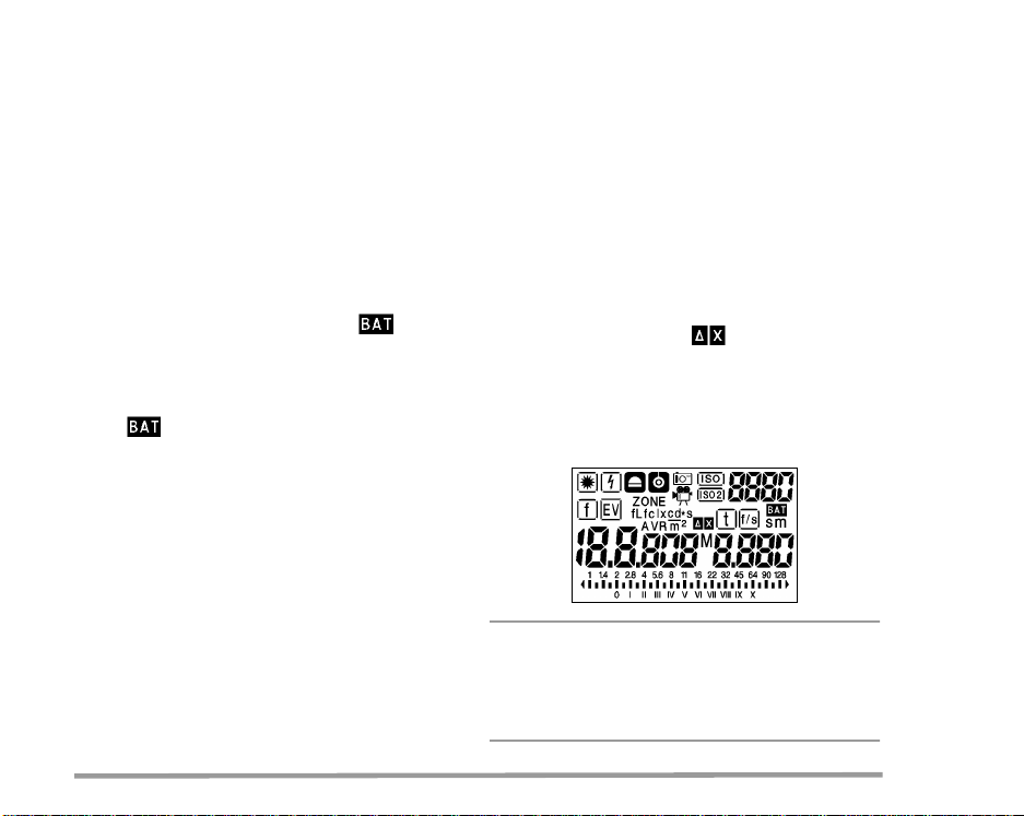
When the battery is running low, the display
appears in addition to the measured values as a
warning to the user.
At this stage, it is advisable to replace the battery
as soon as possible.
When appears on the display alone,
measurements can no longer be taken.
Replace the battery immediately.
To replace the battery, open the battery compartment of the Starlite, remove the old battery and
insert the new one. Observe the "+" and "–"
polarity! Please close the cover of the battery
compartment.
1.2 Self-test
After the new battery has been inserted, the microcomputer will carry out a self-test. Here, every
display segment of the display panel appears.
The self-test takes about 10 s. It can, however,
be interrupted before by pressing any button.
GOSSEN Foto- und Lichtmeßtechnik 7
As soon as the self-test is complete, the factory
preset standard settings are activated.
ISO 100/21° 0/1.0
ISO2 50/18°
f 5.6 t 1/125
EV 12 Flash f 1/60
f/s 24
Warning!
Do not view and do not aim the meter
directly at the sun
You may not only damage your eye, but also ruin
the light-sensitive cell.
Page 8
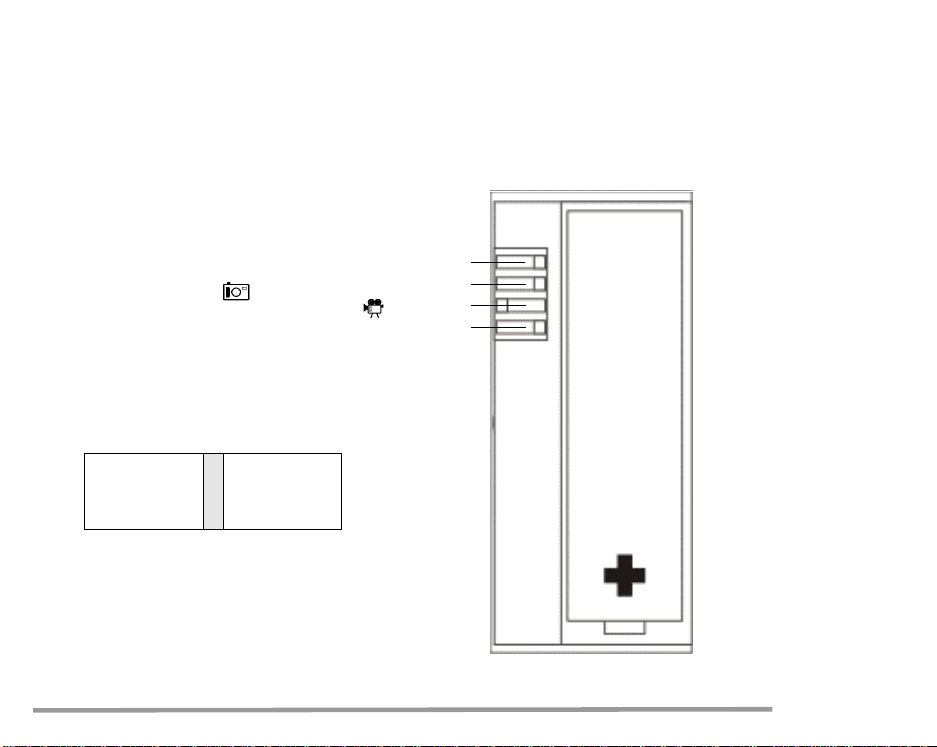
1.3 Selecting the function groups:
DIP switches in the battery compartment
In addition to the standard functions, your Starlite
features a range of additional characteristics and
functions which can be selected using the
"DIP switches" in the battery compartment.
– DIP 1 Selection STILL – Photography
CINE and PHOTOMETRY
– DIP 2 Selection SHUTTER SPEEDS
(1/1 or 1/2)
– DIP 3 Selection DISPLAY UNIT photometry
– DIP 4 Selection Measuring function – ZONES
DIP 4
DIP 3
DIP 2
DIP 1
Zone System
fc fL
1/2 t-Steps
CINE
8 GOSSEN Foto- und Lichtmeßtechnik
4
3
2
1
–
lx cd/m
1/1 t-Steps
STILL
2
Page 9
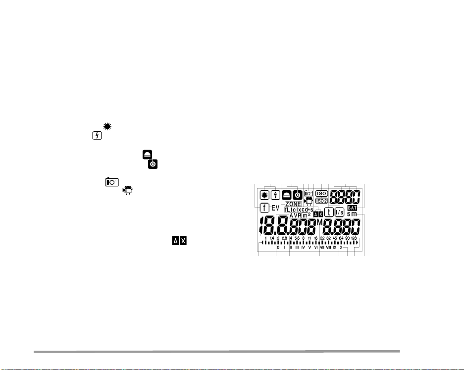
2 Display panel
14 Analogue scale
15 Left digital displays for
2.1 The display panel and its elements
1 Function
– Ambient light
– Flash light
2 Measuring head
– Incident light measuring
– Reflected light measuring
3 Meter functions
– Photography
– f-stop (f)
– Exposure value (EV)
– Correction values
– Multiple flash calculation
– Average (f) – Number of measurings
– Zone
– Ready for flash (F)
– Photometric measuring values
6172
13 3 8
49
10
5
– Cine / Photometry
4 Film speed ISO – ISO2
5 Digital display of the film speed
6 Display signal f – EV
7 Display signal Zone
8 Display – Function correction value
9 Display signal t – f/s
1612151214
10 Battery check warning signal
11 Display signal seconds (s) – minutes (m)
12 Display signal average
AVR and M (memory)
13 Display signal photometry
– Illuminance (lx – fc)
– Luminance (cd/m
– Time integral values
(lx*s – fc*s – cd/m
GOSSEN Foto- und Lichtmeßtechnik 9
2
– fL)
2
*s – fL*s)
16 Right digital display for
– Exposure time (t)
– Extension factor– correction value
– Flash calculation, number of flashes
– Cine speeds (f/s)
17 Zone scale
18 Aperture scale
111817
Page 10
2.1.1 Automatic display illumination
When the lighting conditions are poor (about EV 4
or less), the background lighting of the display is
switched on automatically for 10 seconds.
2.3 Key Lock
It makes sense to activate the key lock to avoid
switching on the Starlite by accident.
– Activating the key lock: press
ISO and ISO2 simultaneously.
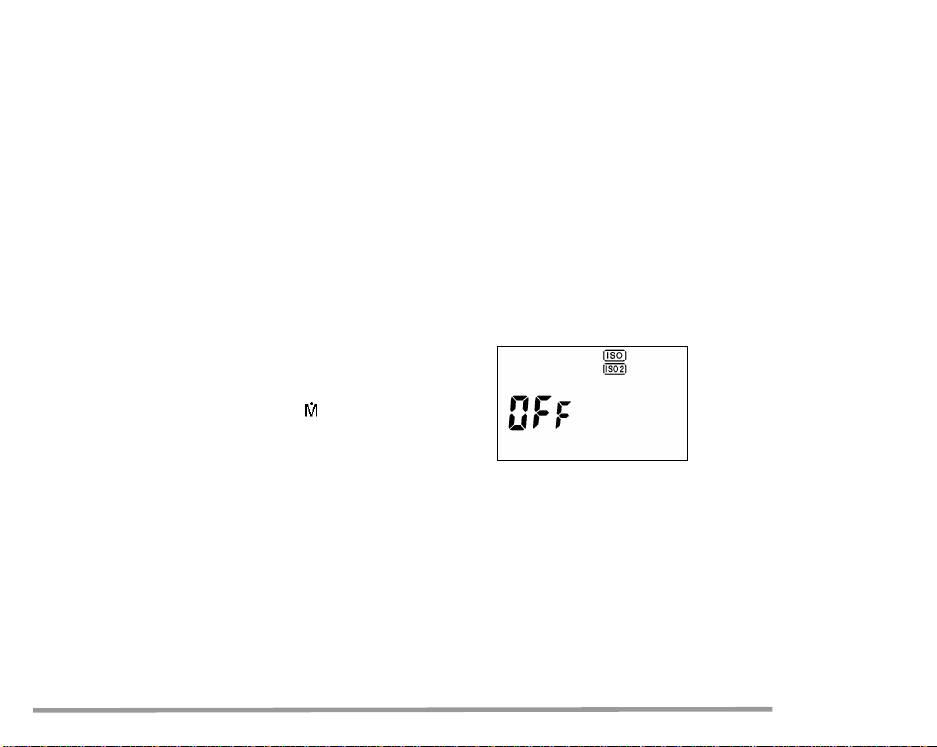
2.2 Display duration
If the Starlite display panel is idle for about 2
minutes, it is switched off automatically.
OFF, ISO and ISO2 appear for 3 seconds on
the display. Then the instrument switches off
automatically.
The measuring values and the preset values
remain stored in memory.
– By pressing anyone of the buttons, you can
recall the measuring value from the memory.
– By pressing the measuring button , a new
measurement is taken.
The measuring values of the last measurement
remain stored in the memory until a new measurement is taken.
The Starlite has separate memories for
ambient and flash light measuring.
If you press any button, OFF, ISO and ISO2 are
displayed again for 3 seconds.
– Deactivating the key lock:
press ISO and ISO2 simultaneously.
10 GOSSEN Foto- und Lichtmeßtechnik
Page 11
3 Operating elements
3.1 ISO – ISO2
Selecting the film speed
You can select two different film speeds with the
ISO and ISO2 buttons.
– Select the film speed by pressing and holding
If the film speed is changed, the last measuring
value is converted to the new ISO settings.
The selected film speed is memorized until it is
changed in accordance with the above mentioned
procedure.
"ISO" or "ISO2". ISO or ISO2 will flash on the
display panel.
– Set the desired ISO value using the setting
wheel.
When another operating function is selected,
the preset film speed is retained in the Starlite
memory.
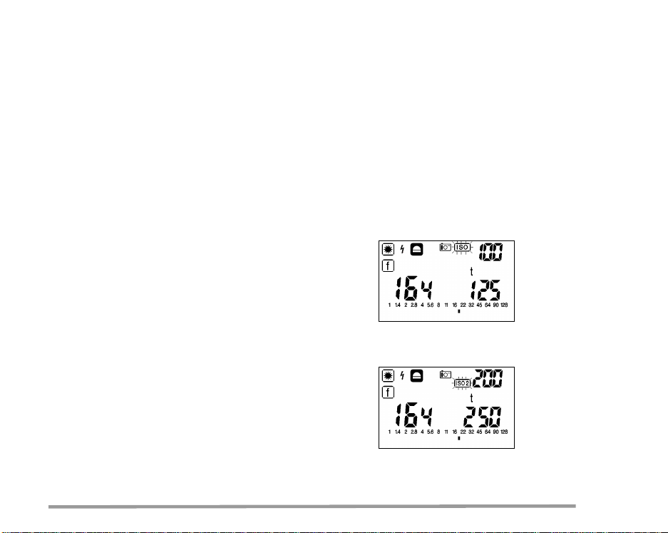
The film speed you have selected, either ISO or
ISO2, appears in the top right corner of the display
panel (ISO2 as long as the ISO2 button is pressed).
When the ISO2 button is pressed, the converted
shutter speed/f-stop values are displayed on the
basis of the last measuring. Therefore, you no
longer have to carry out time consuming calculations when working with 2 films of different speeds.
GOSSEN Foto- und Lichtmeßtechnik 11
Page 12
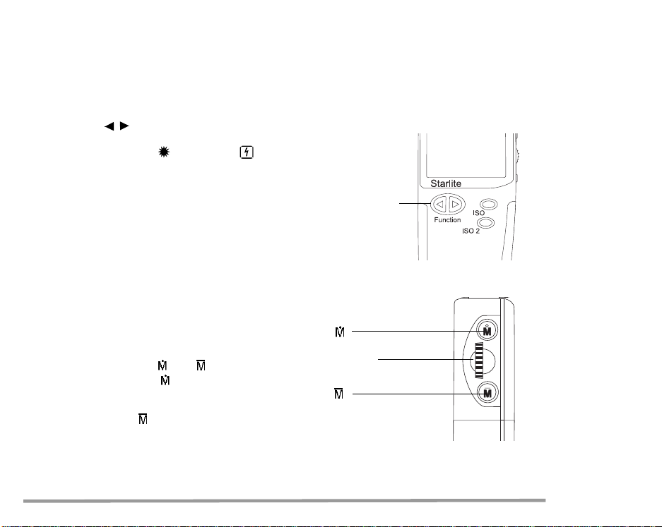
3.2 Function
With the function buttons you can select the measuring modes ambient light or flash light .
Keep the function button pressed and select the
sub-functions time preselection t, f-number preselection f or exposure value EV using the setting
wheel.
Function Buttons
3.3 Setting wheel
The setting wheel allows you to change values
and functions.
– Presetting for ambient, flash and ISO
– Calling up shutter speed/f-stop combinations
after measuring. Multiple flash calculation
– Allocation of zones
– Selection of shutter angles in the CINE function
3.4 Measuring buttons and
Button
Setting wheel
With the measuring button you can trigger off
a new measurement and delete all previous
Button
measuring values.
The measuring button is used for calculating
average values.
12 GOSSEN Foto- und Lichtmeßtechnik
Page 13

3.5 Measuring head with optical viewfinder
1° or 5°
Flat diffuser– spherical diffuser
The measuring head is the optical control center of
Reflected light measuring 5°
Reflected light measuring 1°
the Starlite. The 270° rotating measuring head
provides the basis for effective working in practice.
Caution:
Never try to overwind the bui lt-i n l ock by f orce.
Sooner or later this will cause the connection
between measuring head and basic meter to
break and will have to be repaired!
The following measuring modes can be selected
using the diffuser ring at the measuring head :
– Reflected light measuring 1°, spot measuring
– Reflected light measuring 5°
– Incident light measuring, flat diffuser
– Incident light measuring, spherical diffuser
The optical viewfinder with measuring angles of 1°
and 5° for reflected light measuring is also located
in the measuring head. Due to these measuring
angles it is possible to precisely focus on even the
smallest spots in the subject.
The viewing field is about 12°.
GOSSEN Foto- und Lichtmeßtechnik 13
Incident light measuring,
flat diffuser
Incident light measuring,
spherical diffuser
Diffuser ring
Page 14
4 This is how the Starlite works
4.1 Incident and reflected light measuring
Your Starlite is designed for the enthusiastic
amateur as well as for professional use.
Its rotating measuring head is the optical "control
center", and the following measuring functions can
be set:
– Incident light measuring, diffuser raised:
spherical measuring characteristics
– Incident light measuring, diffuser lowered:
flat measuring characteristics
– Reflected light measuring with 5° measuring
angle through the viewfinder
– Reflected light measuring with 1° measuring
angle through the viewfinder
Thus, the meter can be conveniently used for all
measuring methods including the zone system.
4.1.1Incident light – Spherical diffuser
Set "diffuser raised" with the diffuser ring at the
measuring head. The symbol appears on the
display.
Taking measurements using the incident light
method in particular can produces perfectly
exposed shots. With the incident light mode, the
Starlite measures with its diffuser the incident l ight
14 GOSSEN Foto- und Lichtmeßtechnik
from the subject towards the camera.
This guarantees that the tone quality of the picture
is equivalent to that of the subject.
This is especially important for very bright or dark
subjects. Even under very difficult photographing
conditions, as for example with subjects which
have a lot of contrast, the incident light measuring
method is a much more reliable way of producing
well-exposed and professional pictures.
4.1.2 Incident – Flat diffuser
The lowered/retracted diffuser having a flat
characteristic is suitable for reproductions and
for taking measurements for special lighting technology and photometry.
For this function, the "diffuser lowered" with the
diffuser ring at the measuring head must be set.
Note!
☞
When using the incident light mode with
the setting flat diffusor at the diffusor
ring, the display nevertheless will show the
symbol .
Page 15

4.1.3 Reflected light – 1° Spot measuring
For this function, the setting ring at the base of the
diffuser must be set to the "Reflected light – 1°
symbol. The symbol appears on the display.
In the viewfinder, the measured area corresponds
to the inner, smaller circle.
Your Starlite offers reflected light measuring
with 1° (spot measuring) via the viewfinder in the
measuring head. When you look through the
viewfinder, you can measure using the measuring
buttons and from the camera towards the
object. This way, even the details of a subject can
be accurately measured and analysed through the
viewfinder. Now, only the light reflected from the
subject is detected.
When using the reflected light mode, the measuring values always depend on the reflection of the
subject!
As a result of this, bright subjects are reproduced
darker and are therefore not properly exposed.
GOSSEN Foto- und Lichtmeßtechnik 15
If the exposure measurement is carried out in
accordance with the reflected light measuring
method, it is advantageous to use a grey chart
(18% diffuse reflection). Furthermore, you can
also be given the average values of up to 9 measuring values. The different contrast measuring
values are displayed on the analogue aperture
scale. Subject contrast is measured with the
reflected light measuring method and displayed
by the Starlite on the analogue scale.
4.1.4 Reflected light– 5°
For this function, the "Reflected light measurement
5°" must be set with the diffuser ring at the
measuring head.
The symbol appears on the display.
In the viewfinder, the measuring area corresponds
to the outer, wider circle.
The functions and notes of chapter 4.1.3, page 15
also apply here.
Page 16

5 Measuring functions – Ambient light
– Select with the left function button ambient
light (the last stored measuring value
appears in the display).
– Keep the function button pressed down and
select the corresponding sub-function using
the setting wheel. This function is displayed
in a frame .
– Set the desired value using the setting wheel
alone.
5.1 Aperture priority
– Press the measuring button to take a
measurement.
– The measured exposure time appears on
the right digital display. The f-number is auto-
matically adjusted to the time measured in
1/10 stop increments. Furthermore, the
f-number, which is rounded to 1/2 stop
increments, is displayed as a mark on the
analogue scale.
– Other shutter speed/f-stop combinations
can be selected using the setting wheel.
16 GOSSEN Foto- und Lichtmeßtechnik
Note:
When preselecting f-stop, the stored values
of the last measurement are displayed in 1/10 stop
increments. These are, however, irrelevant, since
a new reading has to be taken.
Page 17

5.2 Exposure time priority
– Press the measuring button to take a
measurement.
– The measured f/stop appears on the left digital
display (resolution in 1/10 stop increments) and
is marked on the analogue scale, rounded to
1/2 stop increments.
– Select other paired f/stop-exposure time values
with the setting wheel.
5.3 Exposure value EV
– Press the button to measure.
– The measured exposure value EV
appears on the left digital display
(resolution in 1/10 stop increments) and
the f/stop is marked additionally on the
analogue scale rounded to 1/2 stops.
– Select other paired f/stop-exposure time values
with the setting wheel.
– Instead of the full exposure time values,
also 1/2 time values can be set by activating
DIP switch 2.
GOSSEN Foto- und Lichtmeßtechnik 17
Page 18

5.4 Contrast measuring
in the t and EV functions
Contrast of the subject
Reflected light measuring
through the viewfinder
– Keep the measuring button pressed
and focus on the various areas of the subject to
be measured.
– The first measuring value appears on the left
digital display. It is constantly displayed as a
reference value (e.g. measurement on a grey
chart) during the course of the entire measuring
process. The actual measuring value flashes
on the analogue scale.
– After releasing the measuring button , the
Illumination contrast
with flat or spherical diffuser
– Keep the measuring button pressed to
measure the different light sources.
– The first measuring value appears on the left
digital display. It is constanly displayed as a
reference value (e.g. main light source) during
the course of the entire measuring process.
The actual measuring value flashes on the
analogue scale.
– After you release the measuring button ,
the total illumination contrast measured
appears on the analogue scale.
measured subject contrast range appears on
the analogue scale.
18 GOSSEN Foto- und Lichtmeßtechnik
Page 19

5.5 Averaging value AVR in the t and EV functions
Reflected light measuring
through the viewfinder
– The first measurement is to be taken with the
measuring button .
– With the AVR measuring button you can
measure up to 8 further contrast spots.
The single measuring values are displayed on
the analogue scale (identical measuring values
are only displayed once, but are taken into
consideration when the average is calculated).
After each measurement with , the average
of all previous measuring values is displayed.
The average AVR appears on the left digital
display: f or EV with f-numbers in 1/10 increments and flashing on the analogue scale,
Incident light with flat or spherical diffuser
Correspondingly, you can determine the average
value of the illumination of the various lights with
the above mentioned procedure. To do this, you
can measure for example your main, fill-in and
background light individually in the studio.
rounded to 1/2 stop increments.
In the middle of the display, the number
of measurements M is displayed
(4 measurements in the example).
GOSSEN Foto- und Lichtmeßtechnik 19
Page 20

5.6 Selecting the exposure time values
In addition to the standard full time values, also
half time values (1/2 TV) can be set at some cameras. For this reason, the Starlite can also be set
additionally to half time values.
The selection is made activating the DIP 2 switch:
– 1/1 full time values
Exposure times are displayed in 1/1 full time
DIP 2
values or when using the CINE function,
in the standard CINE film speeds.
– 1/2 half time values
Exposure times are displayed in 1/2 half time
values. With this function, additional
CINE speeds are displayed.
20 GOSSEN Foto- und Lichtmeßtechnik
Page 21

5.7 Taking measurements in the zone system
This function is mainly used to cope with subject
contrasts in the field of black and white photography.
In addition to the influence of illumination, there
is a further possibility of optimizing the contrast
range of film and paper.
The zone system allows details to be reproduced
in the picture which otherwise would not be visible
and would be lost. A detailed analysis of this
technique would, however, go beyond the scope
of these instructions.
5.7.1 The Starlite and the zone system
The Starlite allocates different brightness ranges
to predefined graduated zones of grey.
Variations of these grey tones from the middle
zone determine the exposure correction and the
changes in the development process, which are to
be applied correspondingly.
GOSSEN Foto- und Lichtmeßtechnik 21
Taking measurements in the zone system
For using the zone system activate the switch
DIP 4 in the battery compartment.
– Set the diffusor ring at the mesuring head to the
„reflected light – 1°“.
– Keep the left function button pressed and select
the sub-function ZONE using the set ting wheel.
– Using the viewfinder, focus on the darkest spot
of the subject, which should still be shown up in
the negative.
– Press the measuring button . The meas. value
will then be automatically allocated to zone V.
– Using the setting wheel, place the measuring
value in the zone where the darkest value
should be, e.g. zone III.
– Now you can measure up to 8 further spots in
the subject using the measuring button –
the most important brightest spot, which should
still show detail in the negative, must be
included.
Page 22

After each measurement using the measuring button the following data are stored and displayed:
– the symbol ZONE and the last measured value
are displayed on the left
– the number of measurements made are
displayed on the right (4 measurements in the
example)
– on the zone scale the currently measured
If, by mistake, you take a zone measurement in
the incident light mode (flat or spherical diffuser),
you are reminded by the flashing diffusor symbol
that you have to set the diffuser ring to 1° spot
metering.
Note down the subject contrast for the film
development and adjust the development time in
accordance with the contrast range.
values are indicated (identical values only
once) and the average of the brightest and
the darkest spot as a flashing dot
When the measuring process is completed and
you then switch over to the function „ambient light“
and the desired measuring function, the value
measured in the zone V is displayed as shutter
speed/f-stop combination. Additionally , the flashing
ZONE symbol is displayed.
Now, you can select further shutter speed/f-stop
combinations using the setting wheel.
22 GOSSEN Foto- und Lichtmeßtechnik
Page 23

6 Measuring functions– Flash light
In essence, flash measuring can be carried out
in all diffuser settings (incident or reflected light
measuring modes). Furthermore, flashes can be
measured with or without a sync cord (cord/noncord). If a sync cord is used, the flash is automatically triggered and measured with the measuring
button .
6.1 Flash light measuring
– Select the function using the right
function button (the last stored measuring
value appears).
– The function is displayed with .
– Set the desired measuring time (sync speed)
using the setting wheel. The measuring times
range from 1 s to 1/1000 s.
– Press the measuring button . The Starlite
is ready to measure for about 45 s (as long as
F is displayed on the display panel).
GOSSEN Foto- und Lichtmeßtechnik 23
– Trigger flash
When using a sync cord, the flash is triggered
and measured automatically when pressing .
– The measured f-number (sum of flash light and
ambient light) appears both in the left digital
display (resolution 1/10 stops) and as a flashing
indicator in the analogue scale rounded to the
nearest 1/2 f-number.
In addition to this, the f-stop for the share of the
ambient light is displayed on the analogue
scale, not flashing.
Page 24
6.2 Flash calculation
for changed measuring times
If the measurement shows that the ambient light
part in relation to the flash light part does not
correspond to your wishes in the overall lighting,
the Starlite calculates on the basis of the measurement taken the influence of altered measuring
times.
Other measuring times can be set directly using
the setting wheel without taking another measurement. The calculation of the new result appears
directly on the display.
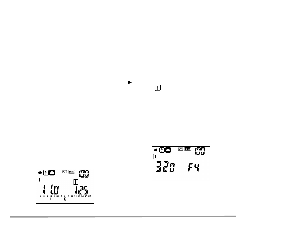
6.3 Multiple flash calculation
Occasionally, the light output from a single flash
may not be sufficient to enable you to work at the
aperture desired. In that case, you can preselect
the desired f-stop. Keep the right function button
depressed and select with the setting wheel the
sub-function . Release the function button and
select the desired f-stop.
The Starlite calculates on the basis of the
measurement already taken the number of flashes
required for the desired f-stop. The digital display
of the time disappears and the number of flashes
required is indicated, (e.g. F4 = 4 flashes)
Note:
In the event of altered measuring times, you
The Starlite will calculate up to a max. of 9 flash
sequences.
must ensure that the flash light duration is not
longer than the preselected measuring time.
If this is the case, a new measurement must be
taken.
24 GOSSEN Foto- und Lichtmeßtechnik
Page 25

6.4 Average value
– Take first measurement using measuring
button
– Measure up to a further 8 flashes using the
In the centre of the display, the number of
measurements M taken is indicated (in the
example 4 measurements).
average value measuring button .
The individual measurements are shown on
the analogue scale (identical values are only
displayed once, but are taken into account in
the calculation of the average value).
After each measurement with , the average
value of all previous measurements is always
displayed. The average value AVR is shown in
the digital display:
at the left with fine adjustment in 1/10 stop
increments and shown as a flashing mark
in the analogue scale, rounded to the nearest
1/2 f-stop. However, the ambient light portion
is not indicated.
GOSSEN Foto- und Lichtmeßtechnik 25
Page 26

7 Taking a measuring outside the measuring range – display range
7.1 T aking a measurement
outside the measuring range
– There is no usable measuring result outside the
measuring range of the Starlite.
– If it is too dark or too bright during the measure-
ment, Err (= Error) appears in the left digital
display.
26 GOSSEN Foto- und Lichtmeßtechnik
7.2 Taking a measurement
outside the display range
If the symbol uu oder nn appears in the right or left
digital display, the measurement has been taken
but the result is outside the display range.
– Use setting wheel to move into the display
range
Page 27

8 Setting and measuring correction values
and extension factors
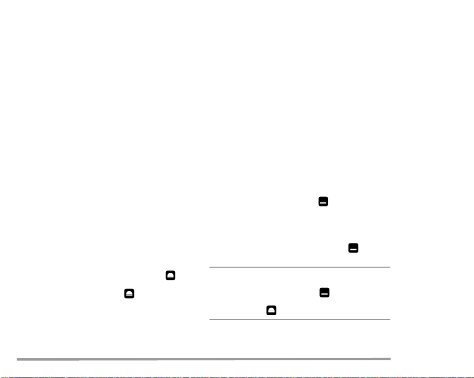
8.1 Setting correction values
– By simultaneously pressing both function
buttons ( and ) you reach the function
-correction values.
– The last valid correction value appears in the
display.
– The desired correction value can be entered or
altered using the setting wheel.
The extension factor is shown in the right digital
display, and the correction value is indicated in
stops. Input in 1/10 EV (small digits) in the range of
±9.9 exposure value stop increments.
For correction values which extend the exposure a
"–" appears in front of the number.
GOSSEN Foto- und Lichtmeßtechnik 27
Example:
–3.1 stops correspond to the extension factor 8.6.
For corrections which shorten the exposure, only
the left display appears as EV difference in stop
increments. By pressing one of the function buttons ( or ) the correction value is stored in the
memory of the Starlite. The symbol appears
in the display.
The correction value is automatically taken into
account in all measuring functions (except for
the photometry).
Page 28

8.1.1 Measuring correction values
Correction values can also be measured directly.
An evenly illuminated surface and constant light
level are required.
Use the Starlite in the reflected light mode at
1° or 5°.
In the function , a reference measurement
can be taken by pressing the measuring button .
Designation rF - - in the digital display.
Then, hold the filter in front of the viewfinder and
press the measuring button .
The light reducing effect will be indicated automatically in the display as EV stop and extension
8.1.2 Deleting correction values
In the function correction values (chapter 8.1,
page 27) you have two possibilities of deleting
pre-programmed correction values:
– by manually resetting using the setting wheel to
EV 0 and extension factor 1.0 or
– by pressing the measuring button
(display rF - -)
– quit the correction value function using the
function button ( or )
Correction value is deleted.
Symbol has disappeared from the display.
factor.
28 GOSSEN Foto- und Lichtmeßtechnik
Page 29

9 CINE meter for cinematographers – PHOTOMETRY
By actuating the DIP 1 switch, the Starlite can be
converted easily and quickly into a fully functional
CINE meter. At the same time switch on the
function photometry .
CINE meter
– Select reflected light or incident light mode at
the measuring head.
– Using the left button, press function ambient
light .
9.1 Preselecting the Cine speeds
– Press and hold the left function button and
using the setting wheel set the speed ’f/s’.
The function is shown in the display as .
– Set the desired CINE speed using the setting
wheel.
– Contrast (chapter 5.4, page 18) and average
value measurements (chapter 5.5, page 19)
can also be carried out.
Using the switch DIP 2 additional CINE speeds
can be switched on.
GOSSEN Foto- und Lichtmeßtechnik 29
9.2 Taking measurements in the CINE
function
– T ake a measurement by pressing the
measuring button
– The measured f-stop appears both in the left
digital display (resolution 1/10 stop increments)
and as an indicator in the analogue aperture
scale rounded to the nearest 1/2 f-stop.
Page 30

9.3 Setting the shutter angle
The shutter angle in the Starlite is preset at the
factory to 180°.
If you are working with other angles which vary
from the shutter angle 180°, you can enter these
directly.
Therefore, no need for lengthy calculation.
– Simultaneously press both function buttons
( and ).
A shutter angle other than 180° has a direct
influence on all measuring functions in the CINE
function; corrected measuring values are shown
directly in the display.
These angle correction values do not influence
the measuring results in the photometry function. Unlike in the photo functions, correction
entries cannot be made here.
The current angle appears in the right display.
– Set the required angle in 5° stop increments
using the setting wheel.
– By pressing a function button ( or ) you
move back into the measuring function.
The selected angle is shown in the display
with the symbol .
30 GOSSEN Foto- und Lichtmeßtechnik
Page 31

10 Photometry
10.1 Selecting the photometric display unit
Use the DIP 1 switch to change over to the
functions CINE/Photometry. Wit h the DIP 3 switch,
you can select either the standardized measuring
units or special ones used in certain English
speaking countries.
– lx, cd/m
2
ment values are displayed in the standardised
units (lx, lxs, cd/m
: the photometric incident measure-
2
, cds/m2).
– fc, FL: the photometric incident measurement
values are displayed in Anglican measuring
units (fc, fcs, fL, fLs). This means the values
10.2 Measuring the illumination
Lux (lx) or footcandle (fc)
– Set the measuring head to incident light
measuring – flat diffusor.
When setting the diffusor at the measuring
head to spherical, an error indication will
appear (flashing ).
– Aim the measuring head in the direction
of the illumination source.
– Take a measurment using the measuring
button .
do not have to be converted.
– Press and hold the left function button
and select the sub-functions illumination or
luminance using the setting wheel.
Depending on the DIP 3 switch setting, lx or fc will
appear in the display.
GOSSEN Foto- und Lichtmeßtechnik 31
Page 32

10.3 Measuring the luminance candela / m2
2
) or footLambert (fL)
(cd/m
– Set the measuring head to reflected light
measuring –1° or 5° . The luminance
function is set and shown in the display.
– Focus on the subject to be measured via the
viewfinder
– Take a measurement using the measuring
button
The selected display unit and measured
luminance are displayed.
10.4 Measuring time-integral values
(lxs, fcs, cds/m
2
, fLs)
– Set measuring head to reflected light
or incident light measuring.
The corresponding display unit is set
and shown in the display.
– Set with the right function button the
function flash light .
– Pre-select the desired measuring time using
the setting wheel; this can be found on the right
hand side of the display panel. Activated half
time stop increments are also displayed.
– Start flash measuring using the measuring but-
ton – cord/noncord (chapter 6.1, page 23).
– The measured value, which is calculated to
1 second, is shown in the pre-selected display
unit.
By preselecting the measuring time, the ambient
light part is correspondingly taken into account.
32 GOSSEN Foto- und Lichtmeßtechnik
Page 33

11 Practical tips
Pre-programming influence values
The Starlite determines precise exposure data in
accordance with DIN 19010. Should you not be
satisfied with your results, remember that there are
independent factors which can affect the success
of your shot:
For example:
– The "true" speed of your film can differ from
that which is stated on the packaging.
– The "true" shutter speeds of your camera can
be different from the speeds given.
– The "true" apertures of your camera can differ
from thos e s t at ed .
– Differences can occur in the development of
your film and the pictures.
In addition, there are purely subjective aspects
and the question of personal taste in the evaluation of finished pictures.
However, you can set your Starlite to the particular features of your camera, the brand of film, your
developing method and your subjective evaluation.
GOSSEN Foto- und Lichtmeßtechnik 33
We recommend the following methods:
Take the reflected light and incident light measurements of several normal subjects (grey chart and
color charts are extremely suitable for this) and
make a series of exposures using values given by
your Starlite for each of these on your film. The
first shot is exposed with the exposure data shown
by the Starlite. For the subsequent shots, these
exposure data are reduced and increased up to
one f-number depending on the raster of the lens.
The lighting conditions may not change during
these exposures.
From the developed pictures you choose the
optimal shots, based on your own personal taste,
and compare the data thereof with the measurements. If its turns out that you prefer shots that
were made with an altered value, you can
programme this value into your Starlite via the
function correction value (chapter 8.1, page 27).
Page 34

12 Contrast and optimal exposure
The basic rules for optimal exposure are that the
brightest areas on the color reversal film (slide) or
the darkest areas on the negative must be sufficiently defined. Personal taste and intentions in
terms of artistic form can of course make these
rules null and void. For this reason, only general
recommendations on optional exposure can be
made.
In comparison to the human eye, film and paper
material can only process a small degree of con-
trast – it is important that this fact be kept in mind.
With the Starlite you can determine illumination
contrast by way of the incident light measuring
method and subject contrast using the reflected
light measuring method. In both cases the analogue display shows the contrast.
34 GOSSEN Foto- und Lichtmeßtechnik
The proper exposure for your subject can not be
achieved if you measure the brightest and darkest
areas. These should be either a medium grey in
the subject or should form the average value from
the measurement results of the brightest and
darkest areas. The Starlite calculates the average
value for you automatically. If you discover that the
subject contrast is greater than can be processed
by your film, you can brighten up the shade, for
example with an umbrella or using a flash, which
will reduce the subject contrast. When considering
the subject contrast from an average value, the
following rules of thumb apply:
Page 35

Negative film
If the difference between important bright and dark
areas does not exceed two stops (EV) between
important bright and dark areas are not exceeded,
each value in between these values could be used
as the setting value; for greater demands the
average value is more suitable. In most cases,
you will achieve a reasonable shot. Rather dense
negatives produce poorer defined contours.
For negatives, the smallest density that can copy
is important - thus, you should use more exposure
rather than too little.
Color reversal film
In comparison to a negative film, a color reversal
film can deal with greater subject contrast, but
offers far less scope for usable exposure.
Measuring the subject contrast is the basis for the
decision as to whether the subject can be reproduced realistically. Unless the subject requires
something else, we recommend that the exposure
Night atmosphere
If you wish to realistically capture the night atmosphere with a lot of dark and little detail, you must
use less exposure than your Starlite displays. This
will prevent your photo being similar to a daytime
shot. However, the Schwarzschild effect often has
the same effect as less exposure.
There are no set rules for this. In order to obtain
experience, take your first shots with unaltered
values that are given by the Starlite.
Schwarzschild effect
Shots with little light require particularly long
exposure times. For all brands of film, what is
known as the Schwarzschild effect occurs here:
The measured times must be increased for the
shot to avoid under-exposure. Various types of film
show the effect to different degrees.
This is why it is not taken into account in the
Starlite. In general, this effect does not occur for
exposures below 1/10 s.
should be based on the highlights.
For color reversal films, the bright areas that are
crucial for the shot are important. Bear this in
mind, and use somewhat shorter rather than
longer exposure. This produces more brilliant and
richer colors.
GOSSEN Foto- und Lichtmeßtechnik 35
Page 36

Some types of color film come with special information or notes with instructions for shots with
long exposure times. But the most up-to-date information can always be directly obtained from the
film manufacturer. The Schwarzschild effect can
also lead to color alterations, which can then be
recitfied with a color correction.
In snow
For snow-covered landscape, the reflected light
measuring method will produce insufficient exposure. Due to the particularly high degree of reflection of snow, important areas of the subject would
be under-exposed.
For measurement adjustment, use 1 to 1.5 EV
higher.
But the better solution is of course to use the
incident light measuring method, which produces
precisely the right measurement result. If you wish
to achieve particular effects, such as subtle shade
nuances in the snow, reduce your exposure by
approximately 1/2 stop.
With the Starlite you can obtain the precise and
suitable exposure data for every photographic
subject. Bear in mind that the film material may not
be able to cope with extraordinarily strong subject
contrasts.
36 GOSSEN Foto- und Lichtmeßtechnik
Page 37

13 Technical data
Measuring capabilities
Incident light measuring
(option of flat or spherical diffusor)
Reflected light measuring,
(measuring angle 1°or 5, viewing field ca. 12°)
Analogue and digital display
Contrast measuring
Average value calculation
(from up to 9 measuring values)
Flash light measuring (Cord/Noncord)
Display of ambient light portion
Multiple flash calculation
Zone system
CINE Meter (preset shutter angle 180°,
other angles adjustable in 5° steps)
Photometry (illumination, luminance,
flash power and luminance)
Light sensor
2 Sbc silicon photo diodes, color-corrected
Shortest measurement distance
approx. 100 cm
Measuring range of ambient light (at ISO 100/21°)
Incident EV –2.5 to +18
Reflected 1° EV 2.0 to +18
Reflected 5° EV 0 to +18
GOSSEN Foto- und Lichtmeßtechnik 37
Measuring range, at flash light (for ISO 100/21°)
Incident f/1.0 to f/128
Reflected 1° f/2.8 to f/128
Reflected 5° f/1.4 to f/128
Measued value processing
digital
Repeatability
±1 digit (= 0.1 EV)
Film speeds
ISO 3/6° to ISO 8000/40° (in 1/3 steps)
Apertures
f/0.5 to f/128
Shutter speeds
Standard speeds: 1/8000 s to 60 min
adjustable additionally:
s: 1/6000, 1/3000, 1/1500, 1/750, 1/350,
1/180, 1/90, 1/45, 1/20, 1/10, 1/6, 1/3,
1/0,7, 1.5, 3, 6, 10, 20. 45
m: 1.5, 3, 6, 10, 20, 45
Flash measuring times (sync speeds)
1 s to 1/1000 s
Page 38

Flash calculation for altered measuring times
1 s to 1/1000 s
Multiple flash calculation
up to 9 flashes
CINE speeds
Standard values:
8,12,16,18, 24, 25, 30, 32, 50, 64
adjustable additionally:
Dimensions
approx. 164 x 66 x 26 mm
Weight without battery
approx. 195 g
Included accessories
Case, strap, battery
Instruction manual
Brief operating instructions
2, 3, 4, 6, 36, 40, 48, 60, 72, 96, 120, 128, 150,
200, 240, 255, 300, 360
Other measuring ranges and display values in
lx, fc, cd/m2, fL, lxs, fcs, cds/m2, fLs
Other displays
Meas. function, range over and range under
(for measuring and display), battery check
Analogue scale
f/1.0 to f/128, zone 0 to X
Correction values/extension factors
EV -9.9 to +9.9 / EF 1.0 to 955
Key lock
Battery
1.5 V (AA) or a 1.2 V rechargable battery
Battery life
For over 5000 measurings with alkaline-mangan batteries, with an assumed flash
Operating temperature range
–10°C to +50°C
Storage temperature range
–20°C to +60°C
Humidity
IP class 54, water-splash resistant
Illumination
0.5 to 199900 lx; 0.05 to 50000 fc
Luminance
0.2 to 30000 cd/m
2
; 0.05 to 9000 fL
Flash illumination
2 to 30000 lxs; 0.2 to 3000 fc*s
Flash luminance
0.3 to 1800 cds/m
2
; 0.1 to 500 fLs
measurement proportion of 30 % and activated display illumination of 3 %
38 GOSSEN Foto- und Lichtmeßtechnik
Page 39

14 Serial interface
On the outside of the Starli te there is an int egrated
serial interface.
15 Service
If repair or adjustment should ever become necessary, please send your St arl ite carefully packed to:
Bogen Photo Corp.
565 East Crescent Avenue
Ramsey, NJ 07446-0506
www.bogenphoto.com
GOSSEN Foto- und Lichtmeßtechnik 39
Recommend books:
The Negative – Anselm Adams
The Zone System – Hank Roelfsema
The Art of Photography – Bruce Barnbaum
Beyond the Zone System – Phil Davis
Page 40

Printed in Germany • Subject to change without notice • 15080 • 2/6.01
Bogen Photo Corp.
565 East Crescent Avenue, Ramsey, NJ 07446-0506
Tel: (201) 818-9500
Fax: (201) 818-9177
email: lesb@bogenphoto.com
www.bogenphoto.com
 Loading...