

Page 1
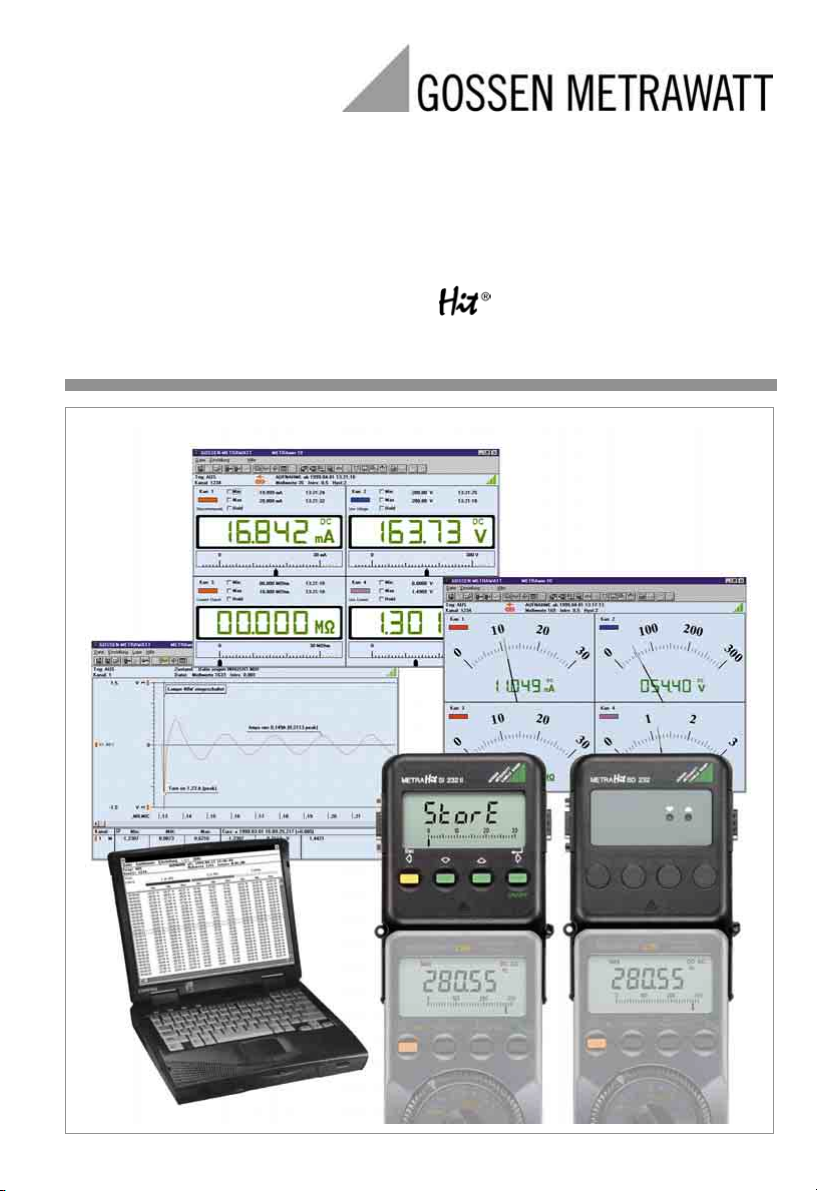
Operating Instructions
SI 232-II, BD 232 Interface Adapter
with METRAwin 10 / METRA Software
for Measuring and Recording Systems with Multimeters
3-348-636-02
6/5.04
Page 2

Contents Page
1 Introduction .............................................................................................................. 3
2 System Requirements .............................................................................................. 3
3 Multimeter, Adapter and METRAwin 10 Operating Modes ....................................... 4
3.1 General Information ............................................................................................ 4
3.2 Saving Measurement Data to Memory in the Multimeter ..................................... 4
3.3 Reading Out the Multimeter’s Memory ................................................................ 4
3.4 Configuring Multimeter Parameters ..................................................................... 5
3.5 Receiving Live Measurement Data from the DMM ............................................... 5
3.6 Saving Measurement Data to the SI232/-II Memory Adapter ............................... 6
3.7 Reading Out Measurement Data from the SI232/-II Memory Adapter and
Configuring Adapter Parameters ......................................................................... 6
4 Adapter Connection and Initial Start-Up .................................................................. 7
4.1 Connecting the Adapter ...................................................................................... 7
4.2 Initial Start-Up - SI232-II Memory Adapter ........................................................... 7
4.3 Initial Start-Up – BD232 Interface Adapter ........................................................... 8
5 Operating Elements, Switching the Adapter ON and OFF, Replacing the Batteries ..... 9
5.1 Keypad, Interface ................................................................................................ 9
5.2 Display .............................................................................................................. 10
5.3 Switching the Memory Adapter ON and OFF .................................................... 11
5.4 Replacing the Batteries ..................................................................................... 11
6 Operating Instructions at a Glance ......................................................................... 12
6.1 Menu Driven Operation ..................................................................................... 12
6.2 Adapter Shortcut Functions .............................................................................. 12
6.3 Shortcuts at the Multimeter ............................................................................... 13
6.4 Menus Overview .............................................................................................. 14
7 Menu Item Descriptions ......................................................................................... 15
7.1 Set Sampling Rate – rAtE .................................................................................. 15
7.2 Set Hysteresis – HYSt ....................................................................................... 15
7.3 Trigger Settings – triG ....................................................................................... 16
7.4 Recording: Duration and Type – durA, CYCLE .................................................. 18
7.5 Internal Time – timE .......................................................................................... 18
7.6 Select Address and Modem Option – Addr, ModEM ......................................... 18
7.7 Set Transmission Speed – bAud-ou, bAud-in ................................................... 19
7.8 Start / Interrupt / Stop Data Recording – StorE, LAbEL ..................................... 19
7.9 View Data at the Adapter – reCAll ..................................................................... 20
7.10 Reading Out Data from the Adapter at the PC / Parameter Configurations – PC 22
7.11 Live Measurement Data Transmission from the Multimeter to the PC – onlinE ... 22
7.12 Clear the Memory – CLEAr ............................................................................... 22
7.13 Query General Information – inFo ...................................................................... 22
8 METRAwin 10 ......................................................................................................... 24
8.1 Installing METRAwin 10 .................................................................................... 24
8.2 Program Documentation / Online Help .............................................................. 24
8.3 Starting METRAwin 10 ...................................................................................... 24
9 Memory Adapter Technical Data ............................................................................ 25
10 Repair and Replacement Parts Service
DKD Calibration Lab and Rental Instrument Service .............................................. 27
11 Product Support ..................................................................................................... 27
2 GOSSEN METRAWATT GMBH
Page 3

1 Introduction
Interface Adapter
Whereas interface adapter BD232 allows for online transmission of measured values from
multimeter to PC, memory adapter SI232/-II is additionally capable of saving multimeter data
on-site without a PC. The values thus stored to memory can subsequently be transmitted to
a PC.
PC-Analysis Software
METRAwin 10 is a high-performance analysis software for use with WINDOWS.
It allows for user-friendly recording, storing, display and documentation of measurement
data from up to 10 multimeters.
Data display is possible in multimeter, recorder or data logger format.
Measurement data are saved in ASCII format for further processing.
The required operating language can be selected for the software.
Upon request we can supply you with an interface description for our multimeters to enable
programming of your own Windows applications.
If you would like to use our multimeters together with LabView software from National Instruments, the corresponding driver is available from our product support team, see chapter 11.
2 System Requirements as from software version 5.0 (32 Bit)
Software
– MS WINDOWS 95/98/ME, NT or 2000
Hardware
– IBM compatible WINDOWS PC, Pentium-CPU or better with 32 MB RAM
– VGA monitor
– Hard disk with at least 20 MB available memory
– 3½“ floppy disk drive
– MICROSOFT compatible mouse
– a WINDOWS supported printer, if required
– 1 serial interface COM1 or COM2
GOSSEN METRAWATT GMBH 3
Page 4
3 Multimeter, Adapter and METRAwin 10 Operating Modes
3.1 General Information
• The address for the adapter and its corresponding multimeter must be identical.
• The baud rates for the adapter and the multimeter must also be the same.
• The multimeter’s sampling rate should be faster than the speed at which data are
requested by the memory adapter or METRAwin 10 software.
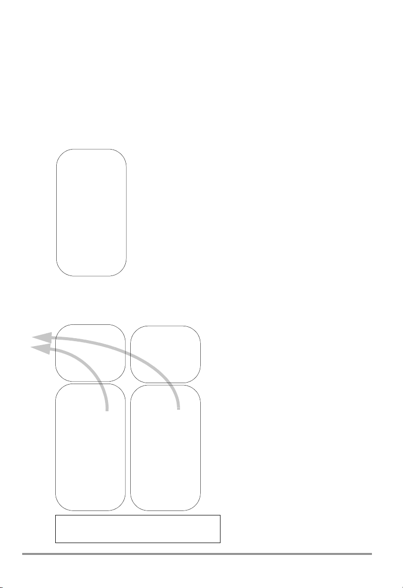
3.2 Saving Measurement Data to Memory in the Multimeter
– for METRAHit 22M, 26M and 29S only
METRAHit, 22M,
26M or 29S only
store
rate:
send off
Rotary Switch:
set to measuring
function
3.3 Reading Out the Multimeter’s Memory
– for METRAHit 22M, 26M and 29S only, with SI232-II or BD232
SI232-II
Adr: 1
Bd-PC: 9600
PC
Bd-MM: 8192
Mode: pc
METRAHit, 22M,
26M or 29S only
Adr: 1
Adapter: SI232
* store/online
rate:
send off
Rotary Switch:
set to measuring
function
METRAwin 10
Set/Device type ..., Set/Channels ...
File/Read memory
4 GOSSEN METRAWATT GMBH
BD232
Adr: 2
Bd-PC 9600
fixed
METRAHit 22M,
26M, 29S only
Adr: 2
Adapter: BD232
rate:
send off
Rotary Switch:
set to measuring
function
Up to 10 devices simultaneously
- when reading out memory,
Up to 4 devices simultaneously
- for live data transmission
* online only with
METRAHit 28S or 29S,
otherwise select store.
Page 5
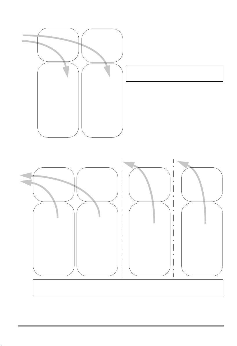
3.4 Configuring Multimeter Parameters
– for all METRAHit 2x with SI232-II or BD232
SI232-II
Adr: 1
Bd-PC: 9600
PC
Bd-MM: 8192
Mode: pc
METRAHit 2x
only
Adr: 1
Adapter: SI232
* store/online
rate:
send off
Rotary Switch:
set to measuring
function
BD232
Adr: 2
Bd-PC 9600
fixed
METRAHit 2x
only
Adr: 2
Adapter: BD232
rate:
send off
Rotary Switch:
set to measuring
function
METRAwin 10
Set/Device type..., Set/Channels ...
* online only with
METRAHit 28S or 29S,
otherwise select store.
3.5 Receiving Live Measurement Data from the DMM
– via adapter, but without saving to memory in the adapter
PC
SI232/-II
Adr: 1
Bd-PC: 9600
Bd-MM: 8192
Mode: on(line)
SI232/-II
Adr: 2
Bd-PC: 9600
Bd-MM: 8192
Mode: on(line)
SI232-II
Adr: 1
Bd-PC: 9600
Bd-MM: 8192
Mode: pc
PCPC
BD232/ RS232
Adr: 1
Bd-PC 9600
fixed
METRAHit 1x, 2x
Adr: 1
Adapt.: SI232
* store/online
rate:
send on
Rotary Switch:
set to measuring
function
max. 4 at once
METRAwin 10
Set/Device type..., Set/Channels ..., File/Start measurement
* online only with METRAHit 28S or 29S, otherwise set to store.
METRAHit 1x, 2x
Adr: 2
Adapt.: SI232
* store/online
rate:
send on
Rotary Switch:
set to measuring
function
METRAHit 2x only
Adr: 1
Adapt.: SI232
* store/online
rate:
send off
Rotary Switch:
set to measuring
function
METRAHit 2x only
Adr: 1
Adapter: BD/RS
rate:
send off
Rotary Switch:
set to measuring
function
SI and BD adapters can be mixed when using any METRAHit 2x. However, only SI adapters
may be utilized if METRAHit 1x/2x are used in combination. If more than 4 adapters are
used, set the baud rate to 19.2 kBd, or to 9.6 kBd for fewer than 4 adapters.
GOSSEN METRAWATT GMBH 5
Page 6
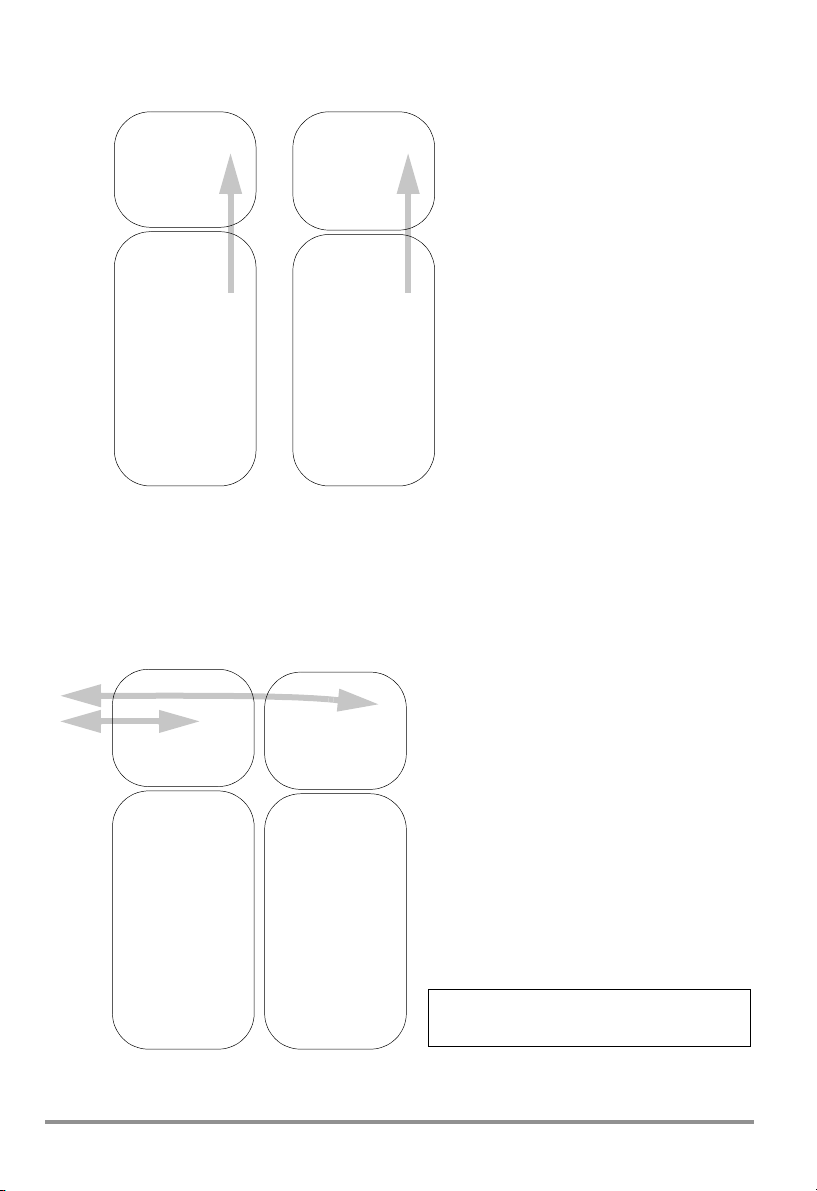
3.6 Saving Measurement Data to the SI232/-II Memory Adapter
The memory adapter can be used with all multimeter versions.
SI232
Adr: 1
Baud: 9600
Mode: store
METRAHit 1x, 2x
Adr: 1
Adapter: SI232
store
rate:
send on
Rotary Switch:
set to measuring
function
SI232-II
Adr: 2
Bd-PC: 9600
Bd-MM: 8192
Mode: store
METRAHit 1x, 2x
Adr: 2
Adapter: SI232
* store/online
rate:
send on
Rotary Switch:
set to measuring
function
* online only with
METRAHit 28S or 29S und SI232-II,
otherwise select store.
Exception: Power and mains disturbance measurements (VAC + dropouts + peaks) with the
29Smultimeter can only be saved to internal multimeter memory.
Note: It is advisable to synchronize the clocks at the multimeter and the adapter before
starting memory mode operation.
3.7 Reading Out Measurement Data from the SI232/-II/-II Memory Adapter and Configuring Adapter Parameters
SI232/-II
SI232/-II
Adr: 1
PC
Baud: 9600
Mode: pc
METRAHit 1x, 2x
Settings have no
significance.
6 GOSSEN METRAWATT GMBH
Adr: 2
Baud: 9600
Mode: pc
METRAHit 1x, 2x
Settings have no
significance.
METRAwin 10
Set/Device type ..., Set/Channels ...
File/Read memory
Page 7

4 Adapter Connection and Initial Start-Up
4.1 Connecting the Adapter
The screw connections between the stacked adapters serve exclusively to secure the
connections at the serial interface plug connectors. Disconnect each individual adapter prior
to transport in order to prevent them from being damaged.
➭ Connect the 9-pin subminiature socket at the connector cable to a vacant COM port at
the PC.
➭ Plug the other end of the cable into the left side of the first adapter. Plug additional
memory adapters into the right side.
➭ Secure the plug connections between the individual memory adapters by tightening the
screws.
➭ Plug the multimeters into the adapters.
Caution
The memory adapter’s housing is made from electrically conductive plastic. It may
!
not be allowed to come into contact with voltage conducting components.
4.2 Initial Start-Up - SI232-II Memory Adapter
Before data can be transmitted to the PC, an individual address must be selected for each
memory adapter, and the memory adapter must be set to transmission mode operation (PC
or online) (see memory adapter operating instructions).
If several memory adapters are used, the same transmission speed must be selected for all
devices.
If more than 4 memory adapters are used in the online mode, a transmission speed of 19,200
baud must be selected in order to assure interference-free data transfer.
➭ Set the required multimeters to data transmission before performing measurement by
simultaneously pressing the DATA key and the ON key.
➭ Check the addresses for the interconnected memory adapters.
➭ Start the PC and METRAwin 10 software.
All interconnected memory adapters are addressed via the serial port and a connection
with the PC is established automatically (see PC function, chapter 6.2, page 12 and
chapter 7.10, page 22).
➭ Activate “Adapter” under menu item “Set/Channels” in the “Interface” field and select the
appropriate port and transmission speed for your system.
➭ Check data transmission to the PC by clicking the “Test” button under menu item “Set/
Channels”.
➭ The memory adapters can be addressed and configured individually under menu item
“Set/Memory adapter”, and the clock and transmission speed can be selected.
➭ In order to perform a measurement, click “Operating mode: ONLINE” under menu item
“Set/Memory adapter”. All memory adapters connected to the interface are placed
online and can be queried with their respective addresses.
➭ Save the selected configuration under menu item “Set/Save configuration”.
This command saves all configurations which have been selected in the “Set” menu.
Measurements can then be performed with the selected configuration.
GOSSEN METRAWATT GMBH 7
Page 8
➭ After selecting the “File/Measure” menu item, the recorded measurement values are
transmitted to the PC and are displayed at the monitor in accordance with the display
mode selected in the “Set” menu.
4.3 Initial Start-Up – BD232 Interface Adapter
➭ Set the multimeter to the data transmission mode before performing measurement by
simultaneously pressing the DATA key and the ON key.
➭ Start the PC and METRAwin 10 software.
A connection to the PC is established automatically and the LEDs at the interface adapter
indicate that data transmission is in process.
1
1
2
3
3
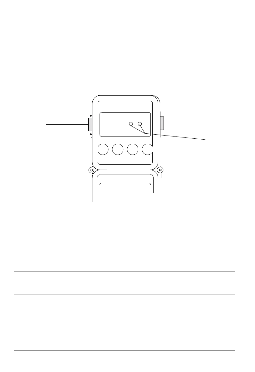
Figure 4.1 Memory Adapter Operating Elements
1 RS232 Interface
The RS232 data interface connects the adapters to one another, and to the PC.
2LEDs
The LEDs indicate data transmission status. The red LED blinks when data are transmitted to the PC, and the green LED blinks when data is transferred from the PC to the multimeter.
3 Connection between two adapters with fastening screws
☞
Note
Please note that chapter 5 and chapter 6 do not apply to this interface adapter
because it does not include any operating elements.
8 GOSSEN METRAWATT GMBH
Page 9
5 Operating Elements, Switching the Adapter ON and OFF, Replacing the Batteries
5.1 Keypad, Interface
1
3
4
DATA ON
21.978 mA
3
5
6
2
7
2
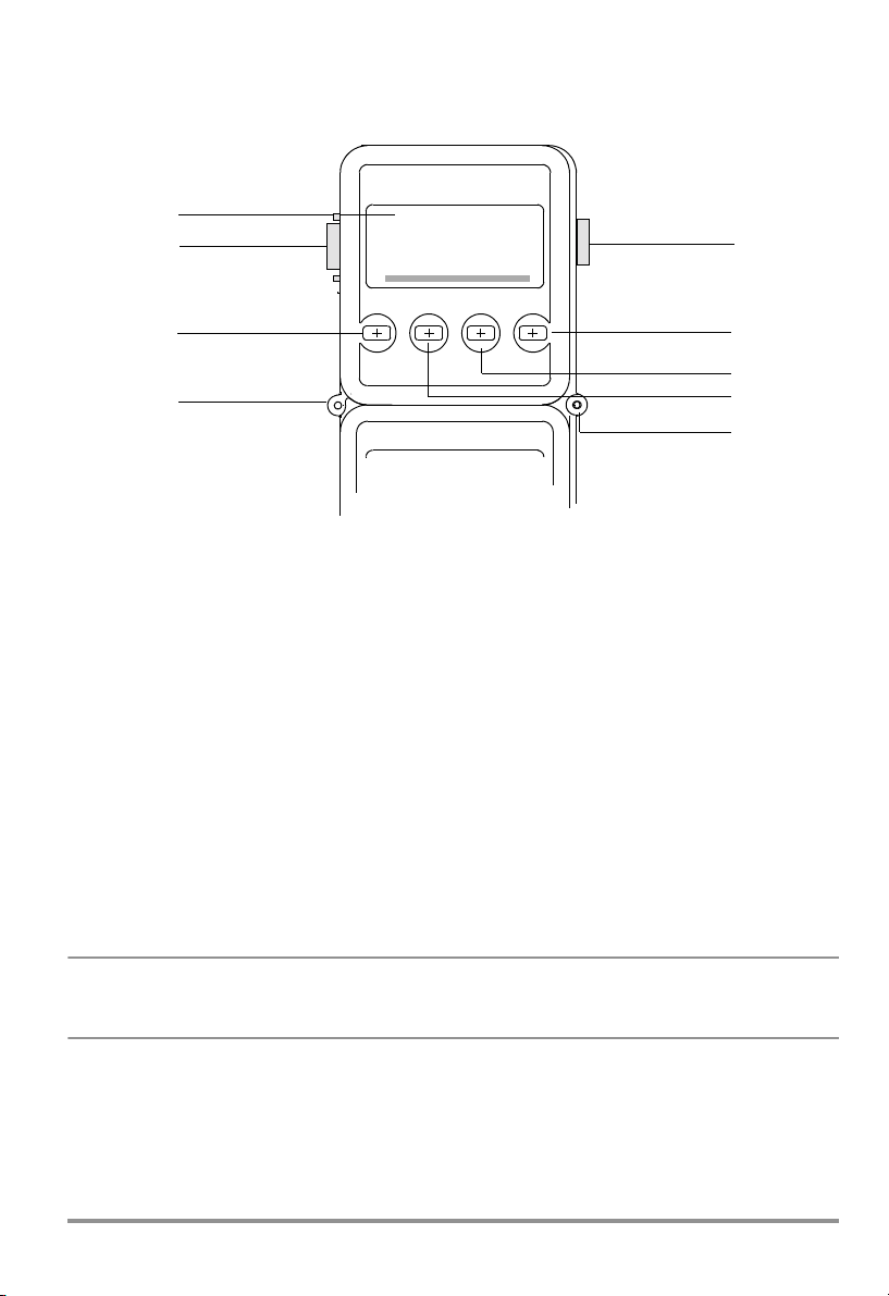
Figure 4.2 Memory Adapter Operating Elements
1LCD
Displays the respective menu item during manual operation of the memory adapter.
2 Connection between two adapters with fastening screws
3 RS232 Interface
The RS232 data interface connects the adapters to one another, and to the PC.
4ESC Key
The ESC key is used to exit the current menu level and return to the next highest level.
5ON/OFF or ENTER Key
Turns the adapter on and off and acknowledges the selected menu item.
6Scroll UP Key
This key is used to select individual menu items by scrolling up, and to increase values.
7Scroll DOWN Key
This key is used to select individual menu items by scrolling down, and to decrease
values.
☞
GOSSEN METRAWATT GMBH 9
Note
Various functions can be selected with hot-key combinations (chapter 6.2, page 12
“Adapter Shortcut Functions”).
Page 10

5.2 Display
3
1
2
Figure 4.3 Memory Adapter LCD
1 Digital Display
The current menu item appears at the 7 segment liquid crystal display during manual
operation of the memory adapter.
When stored data are viewed, measurement values appear at the display in digital format
(menu item “reCAll”, chapter •, page 21).
2 Analog Display
Available memory space can be estimated with the help of the analog display.
For example, the diagram in chapter 5.3, page 11, indicates that the memory is approximately 13/30 full.
When stored data are viewed, measurement values appear at the display in digital format
(menu item “reCAll”, chapter •, page 21).
3 Special Characters
The special characters which appear at the display have the following meanings:
• DATA blinks when data are being received from the multimeter.
• REM blinks when data are being received from the PC.
•The ON triangle (upper left) appears when data are being transferred from the multime-
ter to the memory adapter (with adapter in STORE mode).
• ON (top center) appears when the trigger condition has been fulfilled in the STORE
mode. If no trigger threshold has been selected, ON appears as soon as data recording starts.
•The left-hand overflow arrow next to the analog display always blinks when data are
being saved in the STORE mode.
•The t symbol appears when a time trigger is active in the STORE mode.
•The battery symbol appears when battery capacity has been approximately
depleted. Remaining battery capacity (for alkaline batteries) is sufficient to continue
storing measurement data for at least 96 hours, depending upon the selected sampling rate.
2
/3
10 GOSSEN METRAWATT GMBH
Page 11

5.3 Switching the Memory Adapter ON and OFF
Briefly press the right-hand ON/OFF key in order to switch the memory adapter ON.
The analog scale appears at the LCD along with a display of remaining memory capacity,
above which the last selected operating status is displayed at the left-hand side. The
memory adapter is ready for operation.
Figure 4.4 Initial Display
Press the yellow ESC key until the initial display appears in order to switch the memory
adapter OFF (see above). Then press and hold the ON/OFF key for more than 1 second.
The memory adapter switches itself off automatically after a period of 10 minutes (except for
the time display) if none of its keys have been activated, and if no data have been recorded.
However, the memory adapter is not switched off automatically in the PC, STORE and
ONLINE operating modes. If no signals are received at the memory adapter from the PC or
from the multimeter for a period of approximately 17 seconds, the memory adapter is
switched to the “battery saving” mode.
5.4 Replacing the Batteries
The memory adapter is equipped with two 1.5 V mignon cells in accordance with IEC R 6.
In order to replace the batteries, loosen the two screws at the memory adapter’s housing
base. The batteries are in a holder close to the middle of the printed circuit board.
Remove both depleted batteries and install two 1.5 V mignon cells. The plus and minus
poles of the batteries must correspond to the symbols at the battery holder.
Replace the housing base and retighten the two screws.
Attention: Connect the memory adapter to a PC and start METRAwin 10 software in
order to prevent data loss from the memory adapter during battery replacement. In
!
this way, the memory adapter is supplied with power from the RS232 interface
during battery replacement.
GOSSEN METRAWATT GMBH 11
Page 12

6 Operating Instructions at a Glance
The memory adapter can be operated with the keypad on the device, or more conveniently
with METRAwin 10 software. The most important functions from the operating menu can
also be selected with hot-keys (shortcut function).
6.1 Menu Driven Operation
• The key acknowledges a menu item and opens the respective operating menu level.
The same key with the symbol moves the cursor to the right, for example when entering the time.
•The and keys are used to select menu items by scrolling up or down, or to reduce or
increase parameter values.
• The current menu level can be exited with the yellow ESC key and the display is returned
to the next highest level. The same key with the symbol moves the cursor to the left,
for example when entering the time.
•The and keys are used to select the desired character for numeric parameter settings such as trigger levels and time.
Note: If a menu item is exited, the LCD automatically returns to its initial display.
6.2 Adapter Shortcut Functions
Three important functions can be activated with double key combinations (hot-keys).
• Start / Stop Manual Data Recording – “StorE” Function
Hot-Keys: Start: Simultaneously press the yellow ESC key and the key.
Display: nn.n = memory occupancy as a percentage
Hot-Keys: Stop: Press the
key twice.
• Read Out Data, Configure Parameters – “PC” Function
Hot-Keys: Press and hold the yellow ESC key and then press the key as well.
Display: PC-nn (nn = selected memory adapter address)
Memory adapter parameters can be configured from the PC in this operating mode. Data
can also be transferred from the PC to the multimeter, and back to the PC via the adapter. In
addition to this, recorded measuring data can be uploaded to the PC.
• Live Transmission of Multimeter Measurement Data – “onlinE” Function
Hot-Keys: Press and hold the yellow ESC key and then press the key as well.
Display: on-nn (nn = selected memory adapter address)
Hot-Keys: Stop: Press the yellow ESC key.
Data are transferred from the multimeter to the PC (SEND mode) in this operating mode, but
only in one direction and without being activated from the PC.
Attention
A different address must be selected for each memory adapter
!
(chapter 7.6, page 18).
12 GOSSEN METRAWATT GMBH
Page 13

6.3 Shortcuts at the Multimeter
• Select Normal Operation
– Switch the device off, and then back on.
– Or, if the device is in the measuring mode: press the FUNC and ON keys simultaneously.
– Or, if a selection menu is open: select STORE - STOP and acknowledge with ON.
– Or, if the device is in the SEND mode: select SEND - OFF in the SET menu.
• Transmit Measurement Data to the Adapter – SEND Mode
– Switch the multimeter on by simultaneously pressing DATA and ON.
– Or, select SEND in the SET menu.
• Store Measurement Data at the Multimeter – STORE Mode
– Only applies to 22M, 26M and 29S multimeters
– Simultaneously press FUNC and ON with the multimeter switched on.
GOSSEN METRAWATT GMBH 13
Page 14

6.4 Menus Overview
Initial Display
–
Set Parameters
Data Recording
p. 19
reCAII
Data Viewing
p. 20
PC
PC Mode
p. 22
onlinE
Online Mode
p. 22
Sample
Rate
p. 15
Hysteresis
p. 15
Tri gg er
p. 16
Recording
Duration
p. 18
Type of
Recording
p. 18
rAtE HYSt triG CYCLE tIME Addr bd-ouSEt durA
oFF oFF dd 00001
on on hh:mm 19200
dd
here: 0...6 days
hh:mm
Re-Trigger
PrEtr
on
bL.001
oFF
on
StoP
00.0
d0000
mm:ss
hh:mm
dd
p. 17
oFF
out
In
data
-:--.--
000010:00.00
All
St-In
St-out
p. 17
High Level
Hi
nnnnn
Digits
LAbELStorE
on
Low Level
LO
nnnnn
no
Pre-Trigger
YES
mybloc
128 blocks,
Memory Block
nnnn bEGinStAt xxxxx xxxxxEnd
1000 bytes each
Statistics
p. 20
xxxxN
PC-nn
on-nn
Measurement
Values
p. 21
Primary Values
p. 21
SEE
xxxx1
Meas. Value 1...N
internal
Time
p. 18
dd
dd
Adapter
Address
p. 18
ModEM
YES
oFFrEtri
mm:ss
hh:mm
dd
MIN Value MAX Value
mm:ss
hh:mm
xxxxN
xxxx1SCAn
Primary Value 1...N
Transmission
Speed
p. 19
9600
38400no
Trigger Start Time p. 17
tiME
tiME
mm:ss
hh:mm
hh:mm
dd
hh:mm
dd
bd-in
9600
8192
oFF
on
dd
hh:mm
mm:ss
mm:ss
CLEAr
Clear
Memory
p. 22
no YES
Tes t4
Tes t3
mm:ss
hh:mm
Information
p. 22
inFo
14 GOSSEN METRAWATT GMBH
dd
tiME tESt
Tes t2
Tes t1
diSP
rAm
buSY
YES
no
Acknowledge entry, Enter and (ON/OFF) key
Increase/decrease values, menu scroll keys
Cursor right, menu scroll key
Cursor left, ESC key
Day of the week
dd
Page 15

7 Menu Item Descriptions
7.1 Set Sampling Rate – rAtE
Key Sequence: SEt rAtE m:ss.hh
Settings: m = minutes, ss = seconds, hh = hundredths of a second
The sampling rate determines the time resolution of the data recorded to the memory
adapter.
The special interval -:--.-- is used to save only one measurement value after the STORE
mode has been started. The next time the STORE mode is started, a single measurement
value is stored once again. In this way, measurement values from 2x multimeters are stored
to memory. The sampling rate for these multimeters must be set to DATA, and the corresponding function must be activated with the DATA key at the multimeter. With the multimeter in the SEND mode, only the value determined with this measuring function is transmitted
to the adapter.
Note:
At the expense of time resolution, recording can be performed over longer periods of time if
a long sampling interval is used than are possible with a short sampling interval. Since only
differences are saved to memory, it is advisable to use a relatively short interval to assure
optimum data display, and to select highest possible sensitivity (hysteresis).
7.2 Set Hysteresis – HYSt
Key Sequence: SEt rAtE HYSt nnnnn
Settings: nnnnn = hysteresis in digits
The hysteresis setting allows for efficient use of memory capacity. As long as the measurement values remain within the hysteresis range, no data are recorded to the adapter. If hysteresis ALL or 0 has been selected, all measurement values are stored to the adapter.
Display
5 digit DMM
6 digit DMM
The left-hand hysteresis digits (nnnnn) correspond to the left-hand measurement value digits
(for each measuring range). For example, a value of 00010 entered at the adapter corresponds to 00100 at the 5 digit DMM. Consequently, this would correspond to an hysteresis
of 0.01 V in the 3.0000 V range.
ALL 0 1 4 9 19 00005 00010 00020 00050 00100 00200 00500 01000
ALL 00000 00001 00004 00009 00019 00050 00100 00200 00500 01000 02000 05000 10000
ALL 000000 000001 000004 000009 000019 000050 000100 000200 000500 001000 002000 005000 010000
Adapter Settings 01000 00100 00010
5 Digit Multimeter Effective Value 10000 01000 00100
Measuring Range Effective Hysteresis
300 mV 100 mV 010.0 mV 001.00 mV
3.0000 V 1.0000 V 0.1000 V 0.0100 V
Adapter Settings 01000 00100
6 Digit Multimeter Effective Value 010000 001000 000100
Measuring Range Effective Hysteresis
3.00000 V 0.10000 V 0.01000 V 0.00100 V
30.0000 V 01.0000 V 00.1000 V 00.0100 V
00010
Note:
Hysteresis is independent of measuring range. If the anticipated span of measurement
values is known, it is advisable to set the multimeter to the corresponding range. This also
prevents data loss due to the automatic range selection function.
GOSSEN METRAWATT GMBH 15
Page 16

7.3 Trigger Settings – triG
The trigger setting determines which multimeter measurement values will be stored to the
adapter. Beyond this, storage to memory can be started by means of various trigger types
(st-ou, st-in, out, in). A trigger event occurs when high level is exceeded, or if low level is
fallen short of. Recording may take place before or after the trigger event.
Recording duration depends upon the sampling rate, the hysteresis setting, available memory capacity and the desired recording duration (durA).
The recording command (after all settings are complete) is executed with the hot-key combination ESC and
, or in the StorE menu.
• Start Recording as of the Trigger Event (without re-trigger or pre-trigger)
e.g.
Selected
trigger time:
Thurs. 12:00
Trigger active
a)
Thurs. 12:00
durA
Recording
b)
Trigger event
c)
t
Real-time
a) The prescribed trigger activation time is reached. The trigger is active as of this point in
time.
b) A trigger event occurs. Recording is started and runs for the selected duration (durA).
c) The recording duration (durA) has transpired and recording is stopped – it may also be
stopper earlier if insufficient memory capacity is available, or if the cyclical memory mode
(CYLCE) has been selected.
• Multiple Recordings as of the Trigger Event (with re-trigger)
e.g.
Selected
trigger time:
Thurs. 12:00
Trigger active
a)
Thurs. 12:00
durA
Recording 1
b)
Trigger event
durA
Trigger active Trigger active
c)
d)
Recording 2
e)
Trigger event
Only possible for trigger types triG = in and triG = out.
The pre-trigger must be disabled for this recording mode (PrEtr = oFF)!
a) b), c) Same as above example without re-trigger or pre-trigger.
d) The trigger is once again active as soon as recording has ended.
rEtri = on
PrEtr = oFF!
t
Real-time
• Recording Before the Trigger Event, or Immediate Recording (with pre-trigger)
e.g.
Selected
trigger time:
Thurs. 12:00
Recording
Trigger active
a)
Thurs. 12:00
b)
Trigger event
a) The prescribed trigger activation time is reached. The trigger is active as of this point in
time. Recording begins (da PrEtr = on). A recording duration (durA) can be selected in
this case as well, in order to stop recording.
b) A trigger event occurs and recording is stopped.
16 GOSSEN METRAWATT GMBH
rEtri = disabled
PrEtr = on
t
Real-time
Page 17

• Disabling the Trigger
Key Sequence: SEt ... ... trIG oFF tiME oFF
Settings: triG = oFF, the trigger is disabled
• Enabling the Trigger - Select Level (HI, LO) and Type (out, in, st-ou, st-in)
Key Sequence: SEt ... ... trIG OFF out
HI nnnnn LO nnnnn
PrEtr on oFF rEtri on oFF tiME oFF
Settings: nnnnn = upper / lower trigger level in digits
The left-hand trigger digits (nnnnn) correspond to the left-hand measurement value digits (for
each measuring range). For example, a trigger value of 12300 in the 3.0000 V range corresponds to a 1.2300 V trigger.
Measuring Range Effective Trigger Threshold
300 mV 123 mV 012.3 mV 001.23 mV
3.0000 V 1.2300 V 0.1230 V 0.0123 V
3.00000 V 1.23000 V 0.12300 V 0.01230 V
30.000 V DC 12.300 V 01.230 V 00.123 V
Trig = st-ou: Only measurement values outside of the HI - LO level limits are recorded.
Trig = st-in: Only measurement values within the HI - LO level limits are recorded.
Trig = out: All measurement values are recorded if 1 measurement value is within, and one of
the following measurement values is outside of the HI - LO level limits.
Trig = in: All measurement values are recorded if at least 1 measurement value is outside of,
and one of the following measurement values is within the HI - LO level limits.
Selected Trigger Value in Digits
12300 01230 00123
• Start Recording at a Selected Point in Time and then Activate the Trigger (t.time)
Key Sequence: SEt ... ... trIG OFF out
Settings: dd = day of the week to begin recording
Recording of measurement values is started at a predetermined point in time (trigger time),
after which the trigger is activated.
GOSSEN METRAWATT GMBH 17
HI nnnnn LO nnnnn
PrEtr on oFF rEtri on oFF tiME oFF on
dd hh:mm
hh:mm = time in hours and minutes to begin recording
nnnn = upper / lower trigger level in digits
nn = pre-trigger memory as a percentage
Page 18

7.4 Recording: Duration and Type – durA, CYCLE
• Recording without Time Limits – durA
Key Sequence: SEt ... ... durA on oFF
Settings: oFF = time limiting disabled
Recording is continued until the memory is full. If the CYCLE function has been activated,
memory is overwritten in a cyclical fashion. See also drawing in chapter 7.3, page 16.
• Time-Limited Recording – durA
Key Sequence: SEt ... ... durA ON
dd
Settings: d = number of days (adjustable from 0 to 6)
Recording is ended after the predetermined duration has expired.
See also drawing in chapter 7.3, page 16.
hh:mm
hh = number of hours, mm = number of minutes
• Cyclical Recording – CYCLE
Key Sequence: SEt rAtE ... CYCLE OFF on
Settings: on = cyclical recording activated
When the memory is full, the oldest data are overwritten with new data (FIFO). See also
drawing in chapter 7.3, page 16.
• Record Until Memory is Full – CYCLE
Key Sequence: SEt ... ... CYCLE on OFF
Settings: OFF = cyclical recording deactivated
When the memory full, data recording is ended. See also drawing in chapter 7.3, page 16.
7.5 Internal Time – timE
• Set Current Weekday and Time (no date)
Key Sequence: SEt ... ... tiME dd hh:mm
Settings: dd = current weekday
hh:mm = current time in hours and minutes
Current weekday and time are set with this function.
7.6 Select Address and Modem Option – Addr, ModEM
Key Sequence: SEt ... ... Addr nn ModEM no YES
Settings: nn = 1 ... 15
ModEM = YES, if the adapter is
connected to the PC with a modem
If several memory adapters are connected to the PC, a separate address must be assigned
to each. Address number 1 should be assigned to the first adapter, address number 2 to the
second and so forth.
Note: If only one adapter has been connected, it should be set to address number 1.
18 GOSSEN METRAWATT GMBH
Page 19

7.7 Set Transmission Speed – bAud-ou, bAud-in
• Set Transmission Speed to the PC – bAud-ou
Key Sequence: SEt ... ... bAud-ou 19200
Settings: 9600 (default setting), 19,200 or 38,400 baud
This parameter sets the speed of data transmission between the memory adapter and the
PC. The same baud rate must be selected in METRAwin 10 software at the PC.
• Set Transmission Speed to the Multimeter – bAud-in
Key Sequence: SEt ... ... bAud-in 9600
Settings: 9600 (default setting) or 8192 baud
This parameter sets the speed of data transmission between the memory adapter and the
multimeter.
Note: 8192 baud is the only transmission speed available with METRAHit 1xS multimeters.
METRAHit 2x series multimeters automatically transmit at a speed of 8192 baud if the
RS232 or the SI232 setting has been selected. The SI232-II must also be set to 8192 baud
in this case.
If you want to operate the METRAHit 2x at 9600 baud it must be set to adapter type BD232
(under interface parameters), and the SI232-II must be set to 9600 baud.
7.8 Start / Interrupt / Stop Data Recording – StorE, LAbEL
• Start Data Recording (StorE mode)
Preparations at the multimeter:
– Select the correct adapter type as follows:
SI232-II: AdAPt = SI232 onlinE
SI232: AdAPt = SI232 StorE
(DMM menu: SEt ... ... SI232
– Select a sampling rate, e.g. ratE = 0.05. METRAHit 12S-18S instruments cannot be
adjusted: A fixed baud rate is used which is dependent upon the measuring function.
– Select the required measuring function (V, A, ...), as well as the measuring range.
– Activate measurement data transmission by simultaneously pressing DATA and ON,
or in the menu: SEt – SEnd – on.
Preparations at the adapter:
– Data recording is influenced by the following settings, which should therefore be checked
in advance: sampling rate (rAtE), hysteresis (HYSt), trigger settings (triG), recording dura-
tion (durA), recording type (CYCLE).
– Weekday and time (tiME) should be properly set.
If the contents of the adapter’s memory are to be read out subsequently along with other
adapters, the adapters’ clocks should be set with the help of METRAwin 10 to assure
correct synchronization.
➭ Select manual data recording with the SEt and rAtE functions. The following display must
appear: –:– –.– –
➭ After the adapter has been switched ion, press ESC and ON simultaneously. Memory
occupancy is displayed as a percentage, for example 00.0 if the memory contains no
data. DATA and ON appear briefly at the display.
StorE ...)
GOSSEN METRAWATT GMBH 19
Page 20

Start manual data recording:
Shortcut: Press and hold the yellow ESC key and press the key once for each desired
measurement.
– Or, use the StorE menu (with assignment of a name to the memory block):
Key Sequence: SEt StorE LAbEL no YES mybloc ESC
Settings: mybloc = name of the current memory block (optional)
Start recording with the ESC key.
A new memory block is activated for the storage of data. The new memory block can be
named if desired (LAbEL). The name is made available for purposes of analysis with
METRAwin 10 software. After recording has been activated with the ESC key, the following
display appear:
bL.nnn = ID number for the current memory block between 1 and 128 (continue with )
d.nnnn = ID number for the current measurement value within the memory block between 1
and 1000 (continue with )
nn.n = percentage memory occupancy from 00.1 to 99.9%
The display can be returned to the initial menu with the ESC key without causing interference
to memory mode operation.
• Interrupt Data Recording
Key Sequence: Activate the ESC key twice.
Measurement values can now be queried with the reCAII and SEE functions.
Data recording can be resumed by pressing and holding the ESC key, and simultaneously
pressing the key.
• Stop Data Recording (StorE mode)
Key Sequence: SEt StorE LAbEL no bL.nnn StOP
Settings: StOP = end of data recording
Manual data recording is stopped and the corresponding memory block is closed off.
Shortcut: Simultaneously press the yellow ESC key and the key.
7.9 View Data at the Adapter – reCAll
• Statistical Overview of Stored Data
Key Sequence: rECAll bbbb StAt
bEGin
MIN xxxxx
MAX xxxxx
Settings: bbbb = block number for stored data
bEGin = time recording was begun for data in the memory block
End = time recording was ended for data in the memory block
dd = weekday
hh:mm, mm:ss = time in hours minutes and seconds
MIN, MAX = display minimum and maximum values
xxxxx = measurement value (digital and analog display)
This function displays a statistical overview for a selectable memory block. Memory block ID
number, beginning and ending time of the recording, minimum and maximum values, as well
as the date and time for each, appear at the display.
20 GOSSEN METRAWATT GMBH
dd hh:mm mm:ss End dd hh:mm mm:ss
dd hh:mm mm:ss
dd hh:mm mm:ss
Page 21

• View Individual, Recorded Measurement Values
Key Sequence: rECAll bbbb StAt SEE
(bEGin) ... nnnnn
dd hh:mm mm:ss
... nnnnnm ... (End)
1
Settings: bbbb = block number for stored data
bEGin = flag for beginning of recording within the memory block
End = flag for end of recording within the memory block
nnnnn
dd = weekday
= individual measurement value from 1 to m
1... m
hh:mm, mm:ss = time in hours, minutes and seconds
This function displays the individual, recorded measurement values from within a given
memory block. The individual values within the memory block can be selected by scrolling
up or down with the or the key.
The displays bEGin and End identify the beginning and the end of the memory block.
The time at which the selected measurement value was recorded (weekday and time) can be
read out by repeatedly activating the key.
Note: Pressing and holding the or the key causes rapid scrolling, either up or down,
through the primary recorded values. Downward scrolling is slower than upward scrolling.
• View Primary Values from within a Memory Block
Key Sequence: rECAll bbbb StAt SEE SCAn Select memory block
(bEGin) ... xxxxx
dd hh:mm mm:ss
Settings: bbbb = block number for stored data
bEGin = flag for beginning of recording in the memory block
End = flag for end of recording in the memory block
xxxxx
1... m
dd = weekday
hh:mm, mm:ss = time in hours, minutes and seconds
This function displays the primary values for stored measurement data from a given memory
block. The respective intermediate values are skipped. This function allows for a quick overview of the entire contents of the memory block.
The individual values within the memory block can be selected by scrolling up or down with
the or the key.
The displays bEGin and End identify the beginning and the end of the memory block.
The time at which the selected measurement value was recorded (weekday and time) can be
read out by repeatedly activating the key.
Note: Pressing and holding the or the key causes rapid scrolling, either up or down,
through the primary recorded values. Downward scrolling is slower than upward scrolling.
... xxxxxm ... (End) Select primary value
1
Select recording time
= primary value from 1 to m
GOSSEN METRAWATT GMBH 21
Page 22

7.10 Reading Out Data from the Adapter at the PC / Parameter Configurations – PC
Key Sequence: PC PC-nn
Settings: nn = selected memory adapter address
With this bidirectional operating mode, memory adapter parameters can be configured at
the PC via the interface. Beyond this, recorded measurement data can be uploaded to the
PC.
Shortcut: Press and hold the yellow ESC key and then press the
Note: A different address must be assigned to each of the interconnected memory adapters
(chapter 7.6, page 18), but the address for each adapter must be identical with the address
of its respective multimeter.
key as well.
7.11 Live Measurement Data Transmission from the Multimeter to the PC – onlinE
Key Sequence: onlinE on-nn
Settings: nn = selected memory adapter address
This operating mode allows for the transmission of data from the multimeter directly to the
PC (without activating this function at the PC), and only in one direction. The adapter functions as a transmitter only and does not store any data.
Shortcut: Press and hold the yellow ESC key and then press the key as well.
Note: A different address must be assigned to each of the interconnected memory adapters
(chapter 7.6, page 18). Up to 4 adapters can be operated in this mode without batteries.
7.12 Clear the Memory – CLEAr
Key Sequence: CLEAr no YES
Settings: no = memory content is not deleted
YES = memory content is deleted without any additional security queries
This function deletes the entire contents of the memory adapter.
Caution: Make sure that all recorded measurement values which need to be saved
have been uploaded and archived at a PC before clearing the entire contents of the
!
memory adapter.
7.13 Query General Information – inFo
• Display Current Weekday and Time
Key Sequence: InFO tiME dd hh:mm mm:ss
Settings: dd = current weekday: MO = Monday,
tu = Tuesday, We = Wednesday, th = Thursday,
Fr = Friday, SA = Saturday, SU = Sunday
hh:mm, mm:ss = time in hours, minutes and seconds
The current day and current time are displayed one after the other.
•LCD Test
Key Sequence: InFO tiME tESt dISP Pattern 1 Pattern 2 ...
All possible displays appear at the LCD after the display test has been acknowledged. Various test displays can be selected with the and keys. The software version number is
displayed numerically as part of the test.
22 GOSSEN METRAWATT GMBH
Page 23

Figure 4.5 LCD Test
• Internal Memory Test
Key Sequence: InFO tiME tESt diSP rAM no YES buSY
Settings: no = no memory test is performed
YES = the memory test is started without any additional security queries
After acknowledging YES with the ENTER key, the adapter’s internal memory is tested. Testing
takes about 5 minutes.
All data stored to memory are deleted during the memory test.
buSY appears at the display during testing.
PASS appears at the display when the test has been completed. The adapter is then returned
to its initial display by pressing the ENTER key.
Caution:
Make sure that all recorded measurement values which need to be saved have
!
been uploaded and archived at a PC before starting the memory test.
GOSSEN METRAWATT GMBH 23
Page 24

8 METRAwin 10
8.1 Installing METRAwin 10
WINDOWS version 3.1 or higher is required for installation.
METRAwin 10 is installed automatically.
➭ Insert the program floppy disk into drive A or B.
➭ Open the root directory for the drive into which the disk has been inserted.
➭ Open the README file with the Word notebook which contains the most up-to-date
information and corrections which are not included in these operating instructions.
➭ Start installation by entering INSTALL <ENTER>.
➭ Follow the instructions displayed at the monitor.
8.2 Program Documentation / Online Help
Viewing online help:
Program documentation and online help can be queried at any time with the F1 key.
Printing online help files:
Online help files can be viewed with the .HLP files and printed out with the .WRI files.
Open the .WRI files with the WRITE editor in order to print them out. Open the
MULTIGER.WRI file and print out the online help texts.
8.3 Starting METRAwin 10
After the software has been successfully installed, you should at least connect a multimeter
and set it to the data transmission operating mode before starting METRAwin 10. Simultaneously press the DATA and ON keys in order to set the multimeter to the data transmission
operating mode.
• If the multimeter is equipped with an interface adapter, it should be connected to the PC at
a vacant serial port.
• If the multimeter is equipped with a memory adapter, the memory adapter must now be
connected to the PC for online operation.
The memory adapter and the multimeter are connected to the PC via the serial port by
pressing and holding the yellow ESC key, and by simultaneously pressing the
ter 6.2, page 12).
key (chap-
☞
24 GOSSEN METRAWATT GMBH
Note
A different address must be assigned to each of the interconnected memory
adapters (chapter 7.6, page 18), but the address for each adapter must be identical with the address of its respective multimeter.
Page 25

9 Memory Adapter Technical Data
Supported Measuring Instruments
METRAHit 12S ... 16S, 16I/T, 18S, 14A, 22S/M ... 29S
Operating Elements and Operation
7 segment LCD display and 4 keys.
Almost all parameters can be configured manually, or with a PC via the interface.
Memory
128 kB CMOS memory with battery backup.
Measurement value storage in accordance with the differential value method (compressed)
with adjustable hysteresis. An average of 50,000, and at least 20,000 measurement values
are acquired depending upon whether or not significant signal changes or time spans occur
between the individual measurements. A maximum of 100,000 measurement values are
acquired if only minimal signal changes occur, if the sampling rate is equal to or less than
0.5 s and if hysteresis has been set to ALL.
Real-Time Clock
Real-time clock with battery backup. Max. error: 0.5 minutes per month
Interface
To the Multimeter Optical receiver/transmitter, 950 nm wavelength,
8192 / 9600 baud, 8 bits, no parity, 1 stop bit
To the PC Bidirectional, adjustable baud rate: 9600, 19,200 or 38,400
Number of Adapters Up to10 data memory adapters can be interconnected.
Connections Pin 9 is used for the synchronization of interconnected adapt-
baud, 8 bits, no parity, 1 stop bit
The maximum number depends upon the selected sampling
rate for online PC data acquisition:
With METRAHit 1x
up to 6 adapters at a baud rate of 19.2 kBd
up to 4 adapters at a baud rate of 9.6 kBd
With METRAHit 2x
up to 3 adapters at a sampling rate of 50 ms
up to 8 adapters at a sampling rate of 200 ms
ers in the PC operating mode.
Pins 4 and 7 must be connected to high level at the PC and are
used to supply electrical power to the data memory adapter.
Power is drawn from this source by the data memory adapter
for levels of down to 5 V. Power is drawn from the battery for
lesser voltage levels.
Pin 3 (PC-TXD) is used for negative level generation of the PCRDX signal from the RS232 interface.
With the exception of pin 1 and pin 9 (used for synchronization), all of the interface conductors are looped through to
additional data memory adapters.
GOSSEN METRAWATT GMBH 25
Page 26

Power Supply:
2 ea. 1.5 V mignon cells
Dry cell per IEC R6 type 3006: 1100 mAh
Alkaline-manganese per IEC LR6 type 4006: 2300 mAh
Service Life With alkaline-manganese cells, switched off:
27,000 h = 3 years (without self-discharging)
With alkaline-manganese cells, switched on:
Sampling Rate Service Life
50 ms ... 1 s 750 h
2 s 2,200 h
5 s 4,400 h
10 s 6,600 h
20 s 8,800 h
30 s 10,000 h
60 s 11,000 h
Battery Test Automatic display of the -||- symbol when battery voltage
drops to below approximately 2.5 V, after which approx. 30%
capacity remains.
Power Consumption Batteries are not depleted when the adapter is connected to a
PC with adequate auxiliary power supply (sufficient for up to
approximately 4 series connected adapters).
Consumption from PC control lines approx. 1.1 mA
at a sampling rate of 50 ms
Electrical Safety
Safety low-voltage device per DIN VDE 0411, clearances and
creepage distances per IEC 1010/ DIN VDE 0411
EMC
Interference Suppression Radio interference level N per DIN VDE 0875,
limit value class B per DIN VDE 0871
Temperature Range / Climatic Category
Operating Temperature 0 °C to + 50 °C
Storage Temperature –25 °C to + 70 °C
Climatic Category 2z/0/50/70/75% in compliance with DIN VDE 3540
Mechanical Design
Housing Made from electrically conductive plastic
Dimensions 135 x 97 x 39 mm
Weight approx. 0.25 kg with batteries
Interface To the PC:
9-pin subminiature integrated socket with threaded sleeves
To the Data Memory Adapter:
9-pin subminiature integrated plug with knurled screws
26 GOSSEN METRAWATT GMBH
Page 27

10 Repair and Replacement Parts Service
DKD Calibration Lab and Rental Instrument Service
When you need service, please contact:
GOSSEN METRAWATT GMBH
Service-Center
Thomas-Mann-Strasse 20
90471 Nürnberg, Germany
Phone +49-(0)-911-8602-0
Fax +49-(0)-911-8602-253
E-Mail service@gossenmetrawatt.com
This address is for Germany only.
Abroad, our representatives or establishments are at your disposal.
11 Product Support
When you need support, please contact:
GOSSEN METRAWATT GMBH
Product Support Hotline
Phone +49-(0)-911-8602-112
Fax +49-(0)-911-8602-709
E-Mail support@gossenmetrawatt.com
GOSSEN METRAWATT GMBH 27
Page 28

Edited in Germany • Subject to change without notice • A pdf version is available on the Internet
GOSSEN METRAWATT GMBH
Thomas-Mann-Str. 16-20
90471 Nuremberg, Germany
Phone +49-(0)-911-8602-0
Fax +49-(0)-911-8602-669
E-Mail: info@gossenmetrawatt.com
www.gossenmetrawatt.com
 Loading...