

Page 1
OM-02811-OB02ACE
September 11, 2000
INSTALLATION, OPERATION,
AND MAINTENANCE MANUAL
WITH PARTS LIST
VG SERIES PUMP
MODEL
VG2D3---B
THE GORMAN-RUPP COMPANY D MANSFIELD, OHIO
GORMAN-RUPP OF CANADA LIMITED D ST. THOMAS, ONTARIO, CANADA Printed in U.S.A.
ECopyright by the Gorman-Rupp Company
Page 2

TABLE OF CONTENTS
INTRODUCTION PAGE I --- 1.................................................
WARN ING S --- S E CT I ON A PA G E A --- 1.......................................
IN STA L LAT ION --- SE CTI ON B PA G E B --- 1....................................
Pump Dimensions PAGE B --- 1.....................................................
PREINSTALLATION INSPECTION PAGE B --- 2............................................
POSITIONING PUMP PA GE B --- 2.......................................................
Lifting PA GE B --- 2.................................................................
Mounting PA GE B --- 2.............................................................
SUCTION AND DISCHARGE PIPING PAGE B --- 2.........................................
Materials PA GE B --- 2..............................................................
Line Configuration PAGE B --- 3......................................................
Connections to Pump PAGE B --- 3..................................................
Gauges PA GE B --- 3...............................................................
SUCTION LINES PAGE B --- 3...........................................................
Fittings PA GE B --- 3...............................................................
Strainers PA GE B --- 3..............................................................
Sealing PAGE B --- 3...............................................................
Suction Lines In Sumps PAGE B --- 3.................................................
Suction Line Positioning PAGE B --- 4................................................
DISCHARGE LINES PA GE B --- 4........................................................
Siphoning PA GE B --- 4.............................................................
Valves PA GE B --- 4................................................................
ALIGNMENT PAGE B --- 5..............................................................
Coupled Drives PA GE B --- 5........................................................
V --- Belt Drives PA GE B --- 6.........................................................
OPER AT IO N --- SE CT I ON C PA G E C --- 1......................................
PRIMING PA GE C --- 1.................................................................
Hand Primers PAGE C --- 1..........................................................
Exhaust Primers PAGE C --- 1.......................................................
Auxiliary Ejectors PAGE C --- 2.......................................................
Vacuum Pumps PAGE C --- 2........................................................
STARTING PA GE C --- 2................................................................
Rotation PA GE C --- 2..............................................................
OPERATION PAGE C --- 2..............................................................
Leakage PAGE C --- 2..............................................................
Liquid Temperature And Overheating PAGE C --- 2.....................................
Strainer Check PAGE C --- 3.........................................................
Pump Vacuum Check PAGE C --- 3..................................................
STOPPING PA GE C --- 3................................................................
Cold Weather Preservation PAGE C --- 3..............................................
BEARING TEMPERATURE CHECK PAGE C --- 3..........................................
TR OUB LES HOO TI NG --- S ECT ION D PA G E D --- 1..............................
PREVENTIVE MAINTENANCE PAGE D --- 3...............................................
i
Page 3

TABLE OF CONTENTS
(continued)
PUMP MAINTENANCE AND REPAIR --- SECTION E PAGE E --- 1................
STANDARD PERFORMANCE CURVE PAGE E --- 1........................................
PARTS LIST:
Pump Model V G2D3 --- B PA GE E --- 3.................................................
PUMP AND SEAL DISASSEMBLY AND REAS SEMBLY PAGE E --- 4.........................
Impeller Removal P AGE E -- - 4......................................................
Seal Removal PA GE E --- 4..........................................................
Shaft And Bearing Removal And Disassembly PAGE E --- 5.............................
Shaft And Bearing Reassembly And Installation P AGE E -- - 6............................
Seal Reassembly and Installation P AGE E -- - 7........................................
Impeller Installation P AGE E -- - 8.....................................................
Final Pump Assembly PAGE E --- 8..................................................
LUBRICATION PA GE E --- 8.............................................................
Seal Assembly PAGE E --- 8.........................................................
Bearings PAGE E --- 8..............................................................
Power Source PAGE E --- 9.........................................................
ii
Page 4
VG SERIES OM--02811
INTRODUCTION
This Installation, Operation, and Maintenance
manual is designed to help you achieve the best
performance and longest life from your GormanRupp pump.
This pump is a VG Series, enclosed impeller, centrifugal model with straight-in suction without a
If there are anyquestions regarding the pump or its applicationwhich are n ot covered in this manual or in
other literature accompanying this unit, please contact your Gorman-Rupp distributor, or write:
The Gorman-Rupp Company or Gorman-Rupp of Canada Limited
P.O. Box 1217 70 Burwell Road
Mansfield, Ohio 44901--1217 St. Thomas, Ontario N5P 3R7
Forinformation ortechnicalassistanceon thepowersource,contact thepowersource manufacturer’s local
dealer or representative.
The following are used t o alert maintenance personnel to procedures which require special attention, to
those which could damage equipment, and to those which could be dangerous to personnel:
suction check valve. The pump is designed for
high pressure distribution of liquids containing
specified entrained solids. The basic material of
construction for wetted parts is gray iron. Be sure
the liquid being pumped is compatible with this
material.
Immediate hazards whichWILL resultin
severe personal injury or death. These
instructions describe the procedure required and the injury which will result
from failure to follow the procedure.
Hazards or unsafe practices which
COULDresult in severe personal injury
or death. These instructions describe
the procedure required and the injury
which could result fromfailure to follow
the procedure.
HazardsorunsafepracticeswhichCOULD
result in minor personal injury or product
or property damage. These instructions
describe the requirements and the possible damagewhich could result from failure
to follow the procedure.
NOTE
Instructions to aid in installation, operation, and
maintenance or which clarify a procedure.
PAGE I -- 1INTRODUCTION
Page 5
VG SERIES OM--02811
SAFETY --- SECTION A
These warnings apply to the VG Series
basic pumps. Gorman-Rupp has no
control over or particular knowledge of
the power source which will be used.
Refer to the manual accompanying the
power source before attempting to begin operation.
Beforeattempting toopenorservic e the
pump:
1. Familiarize yourself with thismanual.
2. Disconnect or lock out the power
sourcetoensurethatthe pumpwill
remain inoperative.
3. Allow the pump tocompletelycool
if overheated.
4. Check the temperature before
opening any covers, plates, or
plugs.
5. Close the suction and discharge
valves.
6. Vent the pump slowly and cautiously.
7. Drain the pump.
Thispump isdesignedto handleliquids
containing specified entrained solids.
Do not attempt to p ump volatile, corrosive, or flammable materials whichmay
damage the pump or endanger personnel as a result of pump failure.
Do not operate the pump without the
guards in place over the rotating parts.
Exposed rotating parts can catch clothing, fingers,or tools,causing severe injury to personnel.
Do not operate the pump against a
closeddischarge valveforlong periods
oftime.Ifoperatedagainstacloseddischarge valve, pump components will
deteriorate, and the liquid could come
to a boil, build pressure, and cause the
pump casing to rupture or explode.
Use lifting and moving equipment in
good repair and with adequate capacity
topreventinjuriesto personnel or damage to equipment. Suction and discharge hoses and piping must be removed from the pump before lifting.
After the pump has been positioned,
make certain that the pump and all piping connecti ons are tight, properly supported and secure before operation.
Do not remove plates, covers, gauges,
pipe plugs, or fittings from an overheated pump. Vaporpressure within the
pump can cause parts being disengagedto be ejected withgreatforce.Allowthe pump to completely cool be fore
servicing.
PAGE A -- 1SAFETY
Page 6
INSTALLATION --- SECTION B
OM--02811VG SERIES
Review all SAFETY information in Section A.
Since pump installations areseldom identical,this
section offers only general recommendations and
practices required to inspect, position, and arrange the pump and piping.
Most of the information pertains to a standard
static lift application where the pump is positionedabovethefreelevelofliquidtobepumped.
If installed in aflooded suction applicationwhere
the liquidis supplied to the pump under pressure,
some of the information such as mounting, line
configuration, and priming must be tailored to the
OUTLINE DRAWING
specific application. Since the pressure supplied
to the pump is critical to performance and safety,
be sure to limit the incoming pressure to 50% of
the maximum permissible operating pressure as
shown on the pump performance curve.
Forfurtherassistance,contact yourGorman-Rupp
distributor or t he Gorman-Rupp Company.
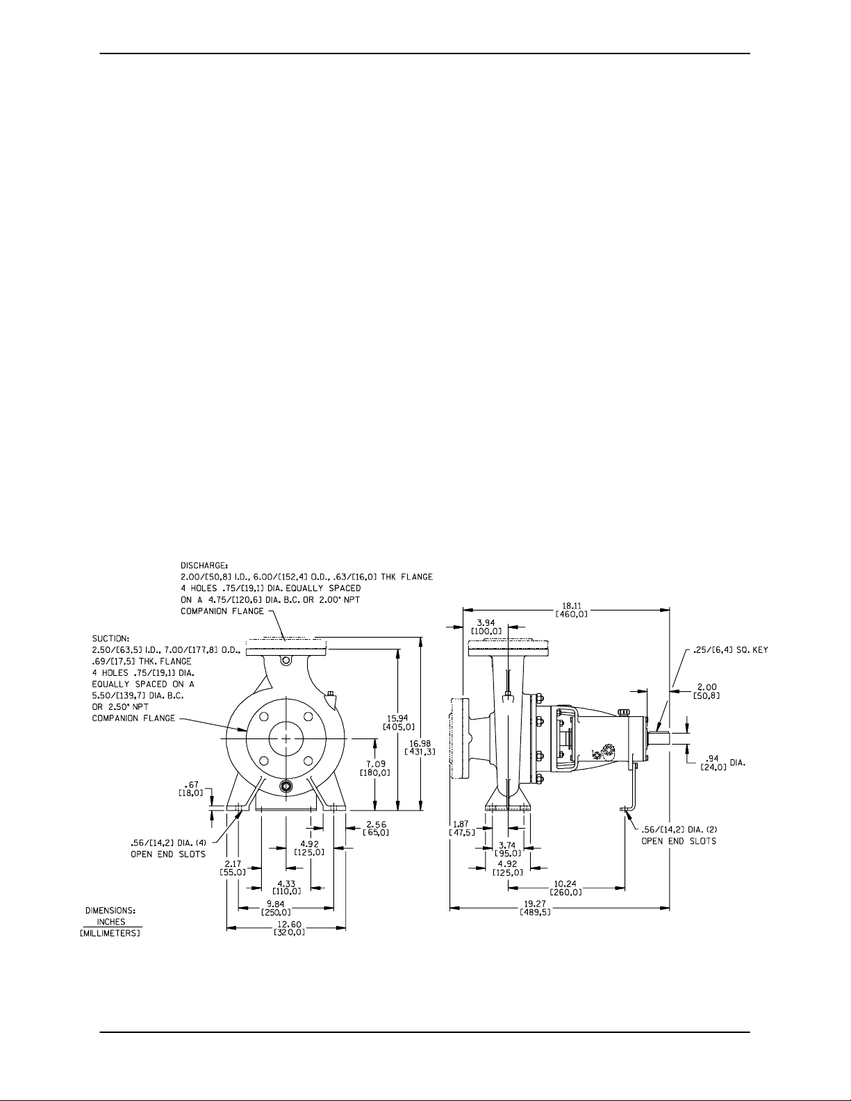
Pump Dimensions
SeeFigure1fortheapproximatephysicaldimensionsofthispump.
Figure 1. Pump Model VG2D3--B
PAGE B -- 1INSTALLATION
Page 7
OM--02811 VG SERIES
PREINSTALLATION INSPECTION
Thepump assembly wasinspected and tested before shipment from the factory. Before installation,
inspect the pump fordamage which may have occurred during shipment. Check as follows:
a. Inspect thepump forcracks,dents,damaged
threads, and other obvious damage.
b. Check for and tighten loose attaching hard-
ware. Since gaskets tend to shrink after drying, check for loose hardware at mating surfaces.
c. Carefullyread all warnings and cautions con-
tained in this manual or affixed to the pump,
and perform all duties indicated. Note the direction of rotation indicated on the pump.
Check that the pump shaft rotates counterclockwise when facing the pump suction.
POSITIONING PUMP
Lifting
Useliftingequipment w ith a capacityofatleast540
pounds (245 kg). This pump weighs approxi-
mately 108 pounds (48,9 kg), not including the
weight of accessories and base. Customer installed equipment such as suction and discharge
piping must be removed before attempting to lift.
Thepumpassemblycanbeseriously
damagedif thecablesor chainsused tolift
andmovetheunitareimproperlywrapped
around the pump.
Mounting
Only operate this pump in the direction indicated by the arrow on the pump body
and on the accompanying decal. Refer to
ROTATION in OPERATION,SectionC.
d. Check all lubricantlevels and lubricate as ne-
cessary.RefertoLUBRICATIONin the MAIN-
TENANCE AND REPAIR section of this manual and perform duties as instructed.
e.Ifthepumpandpowersourcehavebeen
stored for more than 12 months, some of the
components or lubricants may have exceeded their maximum shelf life. These must
be inspected or replaced to ensure maximum pump service.
Locatethepumpinanaccessibleplaceascloseas
practicalto the liquid being pumped. Levelmounting is essential for proper operation.
The pump may have to be supported or shimmed
to provide for level operation or to eliminate vibration.
SUCTION AND DISCHARGE PIPING
Thesizeofthesystempipingisnot always determined by the nominal suction and discharge port
diameter. Factors such as suction lift, discharge
elevation,and friction losses for the complete system must be considered to be sure your a pplicationallowsthe pump tooperate withinthe safe operatingrange shown onpage E-1. In any case, the
suctionlineshouldneverbe smallerthanthepump
inlet.
Materials
If the maximum shelf life has been exceeded, or if
anything appears to be abnormal, contact your
Gorman-Rupp distributor or the factory to determine the repair or updating policy. Do not put the
pump into service until appropriate action has
been taken.
PAGE B -- 2 INSTALLATION
Either pipe or hose maybe used for suction and
discharge lines; however, the materials must be
compatiblewiththeliquidbeingpumped.If hose is
used in suction lines, it must be the rigid-wall, reinforced type to prevent collapse under suction. Us-
Page 8

OM--02811VG SERIES
ing piping couplings in suction lines is not recommended.
Line Configuration
Keep suction and discharge lines as straight as
possible to minimize friction losses. Make minimum use of elbows and fittings, which substantiallyincreasefrictionloss.Ifelbowsarenecessary,
use the long-radius type to minimize friction loss.
Connections to Pump
Before tightening a connecting flange, align it exactlywith the pump port. Never pulla pipe line into
place by tightening the flange bolts and/or couplings.
Lines near the pump must be independently supported to avoid strain on the pump which could
cause excessive vibration, decreased bearing life,
and increased shaft and seal wear. I f hose-type
linesareused, theyshouldhaveadequatesupport
to secure them when filled with liquid and under
pressure.
should be the eccentric type, and should be installedwith the flat part ofthe reducers uppermost
to avoid creating air pockets. Valves are not normally used in suction lines, but if a valve is used,
install it with the stem horizontalto avoid air pock ets.
Strainers
If a strainer is furnished with the pump, be certain
touseit; any sphericalsolidswhichpass througha
strainer furnished with the pump will also pass
through the pump itself.
If a strainer is not furnished with the pump, but is
installed by the pump user, make certain that the
total area of the openings in the strainer is at least
three or four times the crosssection of the suction
line,and that the openings will not permit passage
of solids larger than the solids handling capability
of the pump.
Thispumpisdesignedtohandleupto3/8 inch(9,5
mm) diameter spherical solids.
Sealing
Gauges
Most pumps are drilled and tapped for installing
dischargepressureandvacuumsuctiongauges.If
these gauges are desired for pumps that are not
tapped, drill and tap the suction and discharge
lines not less than 18 inches (457,2 mm) from the
suction and discharge ports and install the lines.
Installationcloserto the pump may result in erratic
readings.
SUCTION LINES
To avoid airpockets whichcouldaffect pumppriming, the suction line must be as short and direct as
possible.Whenoperationinvolvesasuctionlift,the
line must always slope upward to the pump from
the source of the liquid being pumped; if the line
slopes down to the pump at any point along the
suction run, air pockets will be created.
Fittings
Suction lines should bethesame sizeas thepump
inlet. If reducers are used in suction lines, they
Since even a slight leak will affect priming, head,
and capacity, especially when operating with a
high suction lift, all connections in the suction line
should be sealed with pipe dope to ensure an airtight seal. Follow the sealant manufacturer’s recommendations when selecting and applying the
pipe dope. The pipe dope should be compatible
with the liquid being pumped.
Suction Lines In Sumps
If a single suction line is installed in a sump, it
should be positioned away from the wall of the
sumpat a distanceequal to 1 1/2 times the diameter of the suction line.
If there is a liquid flow from an open pipe into the
sump, the flow should be kept away from the suctioninlet because the inflowwill carry air down into
the sump, and air entering the suction line will reduce pump efficiency.
Ifit is necessary to position inflowclose to the suctioninlet,installa bafflebetween theinflowand the
suction inlet at a distance 1 1/2 times the diameter
PAGE B -- 3INSTALLATION
Page 9
OM--02811 VG SERIES
of the suction pipe. The baffle will allow entrained
air to escape from the liquid before it is drawn into
the suction inlet.
If two suction lines are installed in a single sump,
theflowpaths mayinteract, reducing theefficiency
of one or both pumps. To avoid this, position the
suction inlets s o that they are separated by a distance equal to at least 3 times the diameter of the
suction pipe.
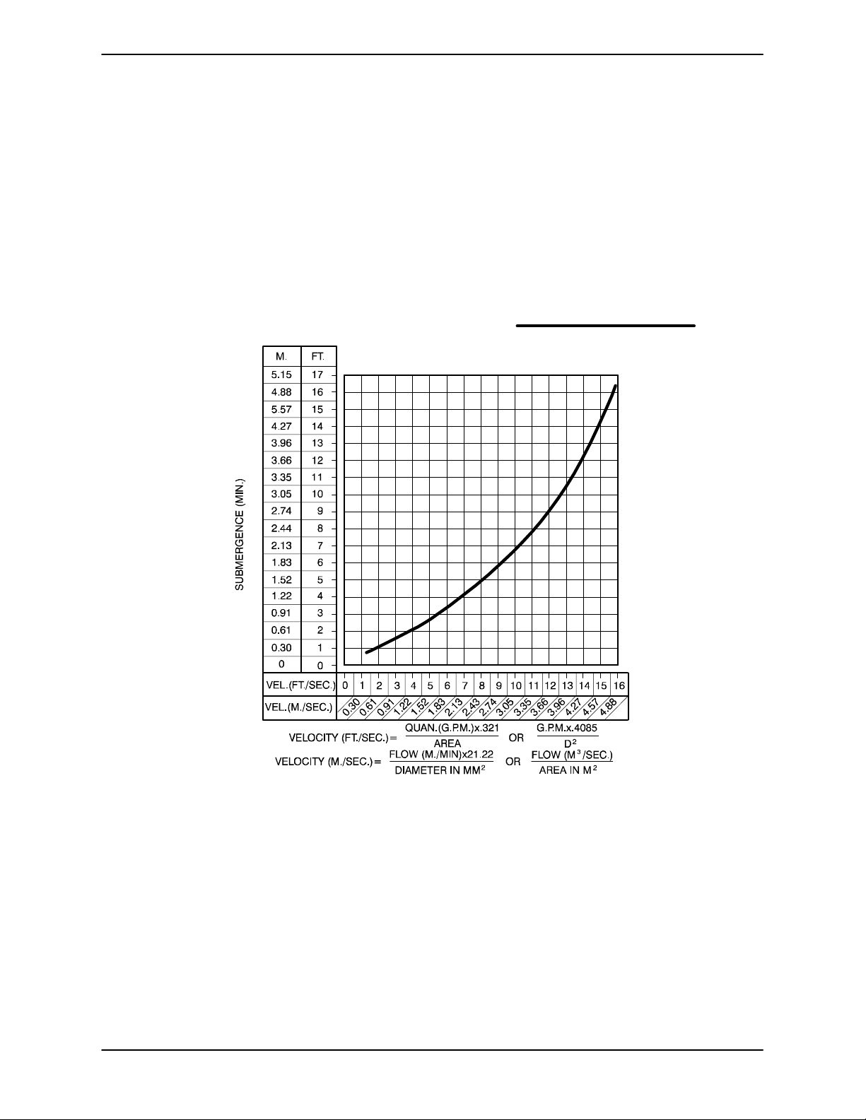
Suction Line Positioning
The depth of submergence of the suction line is
critical to efficient pump operation. Figure 2 shows
recommended minimum submergence vs. velocity.
NOTE
The pipe submergence required may be reduced
by installinga standardpipe increaser fitting at the
endof thesuction line. The largeropening size will
reduce the inlet velocity. Calculate the required
submergence using the following formula based
on the increased opening size (area or diameter).
Figure 2. Recommended Minimum Suction Line Submergence vs. Velocity
DISCHARGE LINES
Siphoning
Donot terminate the discharge lineat a level lower
than that of the liquid being pumped unless a siphon breaker is used in the line. Otherwise, a si phoning action causing damage to the pump
could result.
PAGE B -- 4 INSTALLATION
Valves
A check valvein the discharge lineis normallyrecommended, but it is not necessary in low discharge head applications.
If a throttling valve is desired in the discharge line,
useavalveaslargeasthelargestpipetominimize
friction losses. Never install a throttling valve in a
suction line.
Withhighdischargeheads,itisrecommendedthat
a throttling valve and a system check valve be in-
Page 10

OM--02811VG SERIES
stalled in the discharge line to protect the pump
from excessive shock pressure and reverse rotation when it is stopped.
If the application involves a highdischarge
head, gradually close the discharge
throttling valve before stopping the pump.
ALIGNMENT
Thealignment ofthe pumpand itspower sourceis
critical for trouble-free mechanical operation. In
either a flexible coupling or V-belt driven system,
thedriver and pumpmust bemounted sothat t h eir
shaftsare alignedwith and paralleltoeach other. It
is imperative that alignment be checked after the
pump and piping are installed, and before operation.
Coupled Drives
When using couplings, the axis of the power
source must be aligned to the axis of the pump
shaft in both the horizontal and vertical planes.
Mostcouplingsrequire a specific gap or clearance
between the driving and the driven shafts. Refer to
the coupling manufacturer’s service literature.
Alignspiderinserttypecouplingsbyusingcalipers
to measure the dimensions on the circumference
of the outer ends of the coupling hub every 90 degrees. The coupling is in alignment when the hub
ends are the same distanceapart at all points(see
Figure 3A).
NOTE
Check Rotation, Section C, before final alignment
of the pump.
Whenmountedat the Gorman-Ruppfactory, driver
andpumparealignedbeforeshipment.Misalignment will occur in transit and handling. Pumps
must be checked and realigned before operation.
Beforechecking alignment,tighten the foundation
bolts. The pump casing feet and/or pedestal feet,
andthedrivermountingboltsshouldalsobetightly
secured.
When checking alignment, disconnect
the power source to ensure that the
pump will remain inoperative.
Adjusting the alignment in one direction
may alter the alignment in another direction. check each procedure after altering
alignment.
Figure 3A. Aligning Spider-Ty pe Couplings
Align non-spider type couplings by using a feeler
gaugeortapergaugebetweenthecouplinghalves
every 90 degrees. The coupling is in alignment
whenthehubsarethesamedistanceapartatall
points (see Figure 3B).
Figure3B. AligningNon-SpiderTypeCouplings
Checkparallela djustmentbylayingastraightedge
across both coupling rims at the top, bottom, and
side. When the straightedge rests evenly on both
halves of the coupling, the couplingis in horizontal
parallel alignment. If the coupling is misaligned,
use a feeler gauge between the coupling and the
straightedge to measure the amount of misalignment.
PAGE B -- 5INSTALLATION
Page 11

OM--02811 VG SERIES
ARA
A
V
V-Belt Drives
When using V-belt drives, the power source and
the pump must be parallel. Use a straightedge
alongthesidesofthe pulleystoensure that the pulleys are properly aligned (see Figure 3C). In drive
systemsusingtwo ormore belts, make certainthat
the belts are a matched set; unmatched sets will
cause accelerated belt wear.
MISALIGNED:
SHAFTS
NOT P
LLEL
MISALIGNED:
SHAFTS
NOT IN LINE
ALIGNED:SHAFTS
PARALLEL AND
SHE
ES IN LINE
Figure 3C. Alignment of V-Belt Driven Pumps
Tightenthe beltsinaccordancewiththebeltmanufacturer’s instructions. If the belts are too loose,
they will slip; if the belts are too tight, there will be
excessivepower lossand possiblebearing failure.
Select pulleys that will match the proper speed ratio; overspeeding the pump may damage both
pump and power source.
Do not operate the p ump without the
guard in place over the rotating parts.
exposed rotating parts can catch clothing, fingers,or tools,causing severe injury to personnel.
PAGE B -- 6 INSTALLATION
Page 12

VG SERIES
OM--02811
OPERATION --- SECTION C
Review all SAFETY information in Section A.
Follow the instructions on all tags, labels and
decals attached to the pump.
Thispump isdesignedto handleliquids
containing specified entrained solids.
Do not attempt to p ump volatile, corrosive, or flammable liquids which may
damage the pump or endanger personnel as a result of pump failure.
Pump speed and operating conditions
must be within the performance range
shownonpageE-1.
PRIMING
Install the pump and piping as described in INSTALLATION. Make sure that the piping connec-
tions are tight, and that the pump is securely
mounted. Check that the pump is properly lubricated (see LUBRICATION in MAINTENANCE
AND REPAIR).
the priming device and pump to preserve t he
prime. Start the pump and open the discharge
valveslowlytofill thedischarge line.Wheninstalled
in a flooded suction application, simply open the
system valves and permit the incoming liquid to
evacuatetheair.Afterthepump andpipingsystem
have completelyfilled, evacuate any remaining air
pockets in the pump or suction line.
Never operate this pump unless there is
liquid in the pump casing. The pump will
notprimewhendry.Extended operationof
a dry pump will destroy the seal assembly.
Hand Primers
Hand-operated primers are usually mounted on
the pump and, when operated, draw air out of the
suction line and pump casing. To prime a pump
with a hand vacuum pump, open the cock on the
pump priming line. Operate the hand pump until
liquid flows out of the check valve on the bottom of
the primer pump. Once the pump is primed, close
the valve located between the primer and the
pump so that the prime will not be lost.
HANDLE
This is not a self-priming pump, so an external
priming device must be used if the pump is installed on a suction lift. A foot valve may be installedat theendofthesuctionpipetomaintainthe
prime; however, this may adversely affect pump
performance due to friction loss. Many standard
centrifugalmodelsareequippedwith a hand-operated vacuum pump, exhaust primer, or ejector for
thispurpose. If a primingdevice was notfurnished
with the pump, it may be ordered from the factory
as an option. Before attempting to operate the
priming device, close the discharge throttling
valve. (Installation of a spring-loaded check valve
is also recommended to facilitate priming.) Once
the pump is fully primed, close the valve between
OPERATION PAGE C -- 1
DRAIN
COCK
Figure 1. Hand Primer Assembly
Exhaust Primers
Engine driven pumps normally take advantage of
theengineexhaustgasesbyusingthem tooperate
anexhaust primer. Theexhaustis directedthrough
aventuriwhich creates a vacuum in the pump cas-
Page 13

VG SERIESOM--02811
ingin order tofill the suction line and pumpcasing
with liquid. To prime a pump using an exhaust
primer, open the gas cock in the priming line and
engage theexhaustprimeruntilliquidis thrownout
of the ejector nozzle.
HANDLE
GAS
COCK
Figure 2. Exhaust Primer Assembly
Air can be exhausted to prime a pump by using a
vacuum pump. Either a wet typeor a dry type vacuum pump may be used; however, a wet type is
preferred since it will not be damaged if liquid enters it. If a dry vacuum pump is used, provisions
must be made to keep liquid from entering it.
Auxiliary Ejectors
Ejectors function much likeexhaust primers. They
maybeoperatedbysteam,compressedair,water
or exhaust gases. To prime a pump using an ejector, openthe gas cock in the priming line andoperate the ej ector until liquidis thrown out the ej ector
nozzle.
operated in the wrong direction, pump performance could be adversely affected, and the pump
could be seriously damaged.
Only operate this pump in the direction indicated by the arrow on the pump body
and on the accompanying decal. Otherwise, pump performance could be adversely affected, and the pump could be
seriously damaged.
Consult the operating manual furnished with the
power sourcebefore attempting to start the power
source.
If an electric motor is used to drive the pump, remove V-belts, couplings, or otherwise disconnect
the pump from the motor before checking motor
rotation. Operate the motor independently while
observingthe direction of the motor shaft, or cooling fan.
Ifrotationisincorrecton a three-phasemotor,have
a qualified electrician interchange any two of the
three-phasewiresto changedirection.If rotationis
incorrect on a single-phase motor, consult the literature supplied with the motorfor specific instructions.
OPERATION
Vacuum Pumps
Air can be exhausted to prime a pump by using a
vacuum pump. Either a wet typeor a dry type vacuum pump may be used; however, a wet type is
preferred since it will not be damaged if liquid enters it. If a dry vacuum pump is used, provisions
must be made to keep liquid from entering it.
STARTING
Consult the operations manual furnished with the
power source.
Rotation
The correct direction of pump rotation is counterclockwise when facing the impeller. If the pump is
Leakage
No leakage should be visible at pump mating surfaces, or at pump connections or fittings. Keep all
lineconnectionsandfittingstight to maintainmaximum pump efficiency.
Liquid Temperature And Overheating
The maximum liquid temperature for this pump is
160_ F(71_C).Donotapplyitatahigheroperating
temperature.
Overheating can occur if operated with the valves
in the suction or discharge lines closed. Operating
against closed valves could bring the liquid to a
boil, build pressure, and cause the pump to rupture or explode. If overheating occurs, stop the
OPERATIONPAGE C -- 2
Page 14

VG SERIES
OM--02811
pump and allow it to cool before servicing it. Refill
the pump casing with cool liquid.
Allow an over-heated pump to cool before servicing
. Do not remove plates,
covers,gauges,orfittingsfroman overheated pump. Li quid within the pump
canreach boiling temperatures,andvaporpressure withinthe pump can cause
parts being disengaged to be ejected
with great force. After the pump cools,
drain the liquid from the pump by removing the casing drain plug. Use caution when removing the plug to prevent
injury to personnel from hot liquid.
Strainer Check
Openthesuction line, andread the vacuumgauge
with the pump primed and at operation speed.
Shut off the pump. Thevacuum gauge reading will
immediately drop proportionate to static suction
lift,andshouldthen stabilize.Ifthevacuumreading
falls off rapidly after stabilization, an air leak exists.
Before checking for the source of the leak, check
the point of installation of the vacuum gauge.
STOPPING
Never halt the flow of liquid suddenly. If the liquid
being pumped is stopped abruptly, damaging
shock waves can be transmitted to the pump and
piping system. Close all connecting valves slowly.
On engine driven pumps, reduce the throttle
speed slowlyandallow theengineto idlebriefly before stopping.
If a suction strainer has been shipped with the
pump or installed by the user, check the strainer
regularly, and clean it as necessary. The strainer
shouldalsobechecked ifpumpflowrate beginsto
drop. If a vacuum suction gauge has been installed, monitor and record the readings regularly
to detect strainer blockage.
Never introduce air or steam pressure into the
pump casing or pipingto remove a blockage. This
could result in personal injury or damage to the
equipment. If backflushing is absolutely necessary, liquid pressure must be limited to 50% of the
maximum permissible operating pressure shown
on the pump performance curve.
Pump Vacuum Check
Since this pump does not have a suction check
valve,thedischargelinemust befittedwithacheck
valve if a pump vacuum reading is to be taken.
Withthe pumpinoperative,installavacuumgauge
in the system, using pipe dope on the threads.
Block the suction line and start the pump. At operating speed the pump should pull a vacuum of 20
inches (508,0 mm) or more of mercury. If it does
not, check for air leaks in the seal, gasket, or discharge valve.
Iftheapplicationinvolvesa highdischarge
head, gradually close the discharge
throttling valve before stopping the pump.
After stopping the pump, disconnect the power
source to ensure that the pump will remain inoperative.
Cold Weather Preservation
In below freezing conditions, drain the pump to
preventdamage from freezing.Also, clean outany
solids by flushing with a hose. Operate the pump
for approximatelyone minute; this will remove any
remaining liquid that could freeze the pump rotating parts. If the pump will be idle for more than a
few hours, or if it has been pumping liquids containing a large amount of solids, drain the pump,
and flush it thoroughly with clean water.Toprevent
large solids from clogging the drain port and preventing the pump from completely draining, insert
a rod or stiff wire in the drain port, and agitate the
liquid during the draining process. Clean out any
remaining solids by flushing with a hose.
BEARING TEMPERATURE CHECK
Bearingsnormally run at higher than ambient temperatures because of heat generated by friction.
OPERATION PAGE C -- 3
Page 15

VG SERIESOM--02811
Temperatures up to 160_F(71_C) are considered
normalforbearings,andthey canoperatesafelyto
at least 180_F(82_C).
Checkingbearingtemperaturesbyhand is inaccurate. Bearing temperatures can be measured accurately by placing a contact-type thermometer
against the housing. Record this temperature for
future reference.
A sudden increase in bearing temperature is a
warning that the bearings are at the point of failing
to operate properly. Make certain that the bearing
lubricant is of the proper viscosity and at the correct level (see LUBRICATION in MAINTENANCE
AND REPAIR). Bearing overheating can also be
caused by shaft misalignmentand/or excessive vibration.
When pumps are first started, the bearings may
seem to run at temperatures above normal. Continued operation should bring the temperatures
down to normal levels.
OPERATIONPAGE C -- 4
Page 16

VG-SERIES OM--02811
TROUBLESHOOTING --- SECTION D
Review all SAFETY information in Section A.
Beforeattemptingtoopen orservice the
pump:
1. Familiarizeyourselfwith this manual.
2. Lock out or disconnect the power
source to ensure that the pump wi ll
remain inoperative.
3. Allow the pump to completely cool if
overheated.
4. Check the temperature before opening any covers, plates, or plugs.
5. Close the suction and discharge
valves.
6. Ventthe pump slowlyand cautiously.
7. Drain the pump.
TROUBLE POSSIBLE CAUSE PROBABLE REMEDY
PUMP FAILS TO
PRIME
PUMP STOPS OR
FAILS TO DELIVER
RATED FLOW OR
PRESSURE
Auxiliary priming device faulty or improperly installed.
Discharge check valve open. Check position of handle; close
Strainer clogged. Check strainer and clean if neces-
Air leak in suction line.
Lining of suction hose collapsed.
Leaking or worn seal or pump gasket. Check pump vacuum. Replace
Pump running backwards. Check direction of rotation.
Strainer clogged. Check strainer and clean ifneces-
Air leak in suction line. Correct leak.
Suction intake not submerged at
proper level or sump too small.
Repair priming device or check installation.
valve.
sary.
Correct leak.
Replace suction hose.
leakingorwornsealorgasket.
sary.
Check installationand correctsubmergence as needed.
Impellerorotherwearingpartsworn
or damaged.
Impeller clogged. Free impeller of debris.
TROUBLESHOOTING PAGE D -- 1
Replace worn or damaged parts.
Check that impeller is properly
centered and rotates freely.
Page 17

TROUBLE POSSIBLE CAUSE PROBABLE REMEDY
VG-SERIESOM--02811
PUMP STOPS OR
FAILS TO DELIVER
RATED FLOW OR
PRESSURE (cont.)
PUMP REQUIRES
TOO MUCH
POWER
Discharge throttling valve partially
closed; check that valveis installedimproperly.
Pump speed too slow. Check driver output; check belts
Suction lift t oo high. Measureliftw/vacuumgauge.Re -
Leaking or worn seal or pump gasket. Check pump vacuum. Replace
Liquid solution too thick. Dilute if possible.
Power source t oo small. Check power requirement for ap-
Pump speed too high. Check driver output; check that
Discharge head too low. Adjust discharge valve.
Impeller jammed due to debris or in-
sufficient clearance.
Open discharge valve fully; check
piping installation.
or couplings for slippage.
duce lift and/or friction losses in
suction line.
leakingorwornsealorgasket.
plication. Install larger power
source.
sheaves or couplings are correctly sized.
Disassemblepumpandcheckimpeller.
Liquid solution too thick. Dilute if possible.
Bearing(s) frozen. Disassemble pump and check
PUMP CLOGS
FREQUENTLY
EXCESSIVE NOISE Cavitation in pump.
Discharge flow too slow. Open discharge valve fully to in-
Suction check valve or foot valve
clogged or binding.
Pumping entrained air.
Pump or drive not securelymounted.
Impeller clogged or damaged.
bearing(s).
crease flow rate, and run power
source at maximum governed
speed.
Clean valve.
Reduce suction lift and/or friction
losses in suction line. Record vacuumand pressure gaugereadings
and consult local representative or
factory.
Locateand eliminatesourceof air
bubble.
Secure mounting hardware.
Clean out debris; replace damaged parts.
Suction and discharge lines not properly supported.
Check piping installation for proper
support.
TROUBLESHOOTINGPAGE D -- 2
Page 18

VG-SERIES OM--02811
TROUBLE POSSIBLE CAUSE PROBABLE REMEDY
BEARINGS RUN
TOO HOT
Bearing temperature is high, but
within limits.
Low or incorrect lubricant. Check for proper type and level of
Pump speed too high. Reduce speed of power source.
PREVENTIVE MAINTENANCE
Sincepumpapplicationsareseldomidentical,and
pump wear is directly affected by such things as
the abrasive qualities, pressure and temperature
oftheliquidbeing pumped, thissectionisintended
only to provide general recommendations and
practices for preventive maintenance. Regardless
of the application however, following a routine preventive maintenance schedule will help assure
trouble-free performance and long life from your
Gorman-Rupp pump. For specific questions concerning your application, contact your GormanRupp distributor or the Gorman-Rupp Company.
Record keeping is an essential component of a
good preventive maintenance program. Changes
in suction and discharge gauge readings (if so
Check bearing temperature regu larly to monitor any increase.
lubricant.
equipped) between regularly scheduled inspections can indicate problems that can be corrected
before system damage or catastrophic failure occurs.The appearance of wearingpartsshouldalso
bedocumentedat eachinspectionfor comparison
as well. Also, if records indicate that a certain part
(such as the seal) fails at approximately the same
duty cycle, the part can be checked and replaced
beforefailureoccurs, reducing unscheduleddown
time.
For new applications, a first inspection of wearing
partsat250hourswillgiveinsightintothewearrate
foryourparticularapplication.Subsequentinspections should be performed at the intervals shown
on the chart below. Critical applications should be
inspected more frequently.
TROUBLESHOOTING PAGE D -- 3
Page 19

VG-SERIESOM--02811
Preventive Maintenance Schedule
Service Interval*
Item
General Condition (Temperature, Unusual
Noises or Vibrations, Cracks, Leaks,
Loose Hardware, Etc.) I
Pump Performance (Gauges, Speed, Flow) I
Bearing Lubrication I R
Seal Lubrication (And Packing Adjustment,
If So Equipped) I R
V-Belts (If So Equipped) I
Air Release Valve Plunger Rod (If So Equipped) I C
Front Impeller Clearance (Wear Plate) I
Rear Impeller Clearance (Seal Plate) I
Check Valve I
Pressure Relief Valve (If So Equipped) C
Pump and Driver Alignment I
Shaft Deflection I
Bearings I
Bearing Housing I
Piping I
Driver Lubrication --- See Mfgr’s Literature
Daily Weekly Monthly Semi-
Annually
Annually
Legend:
I = Inspect, Clean, Adjust, Repair or Replace as Necessary
C= Clean
R= Replace
* Service interval based on an intermittent duty cycle equal to approximately 4000 hours annually.
Adjust schedule as required for lower or higher duty cycles or extreme operating conditions.
TROUBLESHOOTINGPAGE D -- 4
Page 20

OM--02811VG SERIES
PUMP MAINTENANCE AND REPAIR --- SECTION E
MAINTENANCE AND REPAIR OF THE WEARING PARTS OF THE PUMP WILL MAINTAIN PEAK
OPERATING PERFORMANCE.
STANDARD PERFORMANCE FOR PUMP MODEL VG2D3--B
Basedon70_ Fclearwater at sea level with minimum suction lift. Since pump installations are seldom identical, your performance may be different
due to such factors as viscosity, specific gravity,
elevation, temperature, and impeller trim.
Contact the Gorman-Rupp Company to verify performance or part numbers.
Pump speed and operating condition
If your pump serial number is followed by an “N”,
your pump is NOT astandardproductionmodel.
MAINTENANCE & REPAIR PAGE E -- 1
points must be within the continuous performance range shown on the curve.
Page 21

OM--02811 VG SERIES
SECTION DRAWING
Figure 1. Pump Model VG2D3---B
MAINTENANCE & REPAIRPAGE E -- 2
Page 22

OM--02811VG SERIES
PARTS LIST
Pu mp Mo del V G2D 3 --- B
(From S/N 1191621 up)
Ifyour pump serialnumber is followedbyan “N”,your pumpis NOT a standard production model. Contact
the Gorman-Rupp Company to verify part numbers.
ITEM
PART NAME PART
NO.
NUMBER
MAT’L
CODE
QTY ITEM
NO.
PART NAME PART
NUMBER
MAT’L
CODE
QTY
1 PUMP CASING 26821---737 --- ------ 1
IMPELLER 26821---102 --- --- --- 1
2
SEAL ASSY 25271---044 --------- 1
3
SHAFT SLEEVE 26821---222 --- --- - -- 1
4
SHAFT SLEEVE O---RING 25154---020 -- ------- 1
5
6 SEAL COLLAR 26821---032 --- --- --- 1
7 SETSCREW 26821---942 --- --- --- 2
8
SEAL CAP GSKT 26821---462 --- --- --- 1
9 DISCHARGE STICKER 6588BJ --- --- --- 1
10 SEAL PLATE GSKT 26821---422 --- --- --- 1
11 SEAL PLATE 26821---684 --- --- --- 1
12 WASHER 26821---546 --- --- --- 8
13 STUD 26821---892 --- --- --- 8
14 HEX NUT 26821---934 --- --- --- 8
15 STUD 26821---879 --- --- --- 4
16 HEX NUT 26821---932 --- --- --- 4
17 NAME PLATE 38814---043 13990 1
18 DRIVE SCREW BM#04---03 17000 2
19 HEX HD CAPSCREW 22645---131 ----- ---- 4
20 BEARING CAP 26821---072 --- ------ 1
21 BEARING HOUSING 26821---066 ------ --- 1
22 RETAINING RING 26821---382 --- --- --- 1
23 ROTATION DECAL 2613M --------- 1
24 LUBE DECAL 38816---074 --- --- --- 1
25 OIL INLET PLUG 26821---616 --- --- --- 1
26
OUTBR D B ALL BRG S39 0 --- --- --- 1
BRG CAP GSKT 26821---402 --- --- --- 1
27
28 BEARING CAP 26821---072 --- ------ 1
29 HEX HD CAPSCREW 22645---131 ----- ---- 4
30
OUTBRD OIL SEAL 26821---632 --- --- --- 1
SHAFT KEY N0406 15990 1
31
REPAIR IMP SHAFT 26821---172 --- --- --- 1
32
---INCLUDES ITEMS 31, 48 AND 49
33 HEX HD CAPSCREW 22645---131 ----- ---- 1
34 WASHER K05 15991 1
35 FOOT 26821---202 --- --- --- 1
36 BRG SNAP RING 26821---382 --- --- --- 1
37 SIGHT GAUGE 26821---611 --- --- --- 1
38 PIPE PLUG P06 15079 1
39
INBRD BALL BRG 26821---331 --------- 1
BRG CAP GSKT 26821---402 --- --- --- 1
40
INBRD OIL SEAL 26821- --632 --- --- --- 1
41
42 DEFLECTOR 26821---492 ------ --- 1
43 STUD 26821---873 --- --- --- 4
44 HEX NUT 26821---931 --- --- --- 4
45 SEAL CAP 26821---242 --- --- --- 1
46 PIPE PLUG P04 15079 1
47 IMPELLER WASHER 26821---546 --- --- --- 1
48
IMPELLER NUT 26821---131 --------- 1
IMPELLER KEY 26821---262 --- ------ 1
49
50 SUCTION STICKER 6588AG -- --- ---- 1
51 PIPE PLUG P04 15079 1
NOT SHOWN:
INSTRUCTION TAG 38817---011 --- --- --- 1
INSTRUCTION TAG 38817---024 --- --- --- 1
OPTIONAL:
NPT SUCTION FLANGE 1675 10010 1
SUCTION FLANGE GSKT 1675G 18000 1
NPT DISCH FLANGE 1688A 10010 1
DISCH FLANGE GSKT 1673G 18000 1
STD STRAINER 2184 --- ------ 1
VITON SEAL 25271---043 --- --- --- 1
BRONZE IMPELLER 26821---082 --- ------ 1
INDICATES PARTS RECOMMENDED FOR STOCK
MAINTENANCE & REPAIR PAGE E -- 3
Page 23

OM--02811 VG SERIES
PUMP AND SEAL DISASSEMBLY
AND REASSEMBLY
Review all SAFETY information in Section A.
Followtheinstructionson all tags,labelanddecals attached to the pump.
This pump requires littleservice due to its rugged,
minimum-maintenance design. However, if it becomesnecessarytoinspectorreplacethewearing
parts, followthese instructions which are keyed to
thesectionalview(seeFigure1)and theaccompanying parts list.
As described on the following pages, this manual
willalert personnelto known procedures which require s pecial attention, to those which coulddamage equipment, and to those which could be dangerousto personnel. However, this manualcannot
possibly anticipate and provide detailed precautions for every situation that might occur during
maintenanceofthe unit.Therefore,itis the responsibilityof the owner/maintenance personnel to ensure that only safe, established maintenance proceduresare used, andthat anyproceduresnotaddressedinthismanualareperformedonlyafterestablishingthat neitherpersonalsafetynorpumpin tegrity are compromised by such practices.
Beforeattemptingtoservicethe pump, disconnect
or lock out the power source and take precautions
to ensure that it will remain inoperative. Close all
valves in the suction and discharge lines.
5. Close the suction and discharge
valves.
6. Vent the pump slowly and cautiously.
7. Drain the pump.
Use lifting and moving equipment in
good repair and with adequate capacity
topreventinjuriesto personnel or damage to equipment.
Impeller Removal
Foraccess to the impeller(2) orseal assembly (3),
the pump casing (1) must be separated from the
seal plate (11).
Drain the suction and discharge piping and re move it from the pump. Remove the casing drain
plug (46) and drain the pump. Clean and reinstall
the drain plug.
Remove the hardware securing the pump casing
to the base. Wedge a block of wood under the
bearinghousing (21)to support the housing when
the casing is removed.
Remove the hardware (12 and 14) and separate
the pump casing from the seal plate. Tie and tag
any leveling shims used under the casing mounting feet. Remove the seal plate gasket (10) and
clean the mating surfaces.
Beforeattempting toopenorservic e the
pump:
1. Familiarize yourself with thismanual.
2. Disconnect or lock out the power
sourcetoensurethatthe pumpwill
remain inoperative.
3. Allow the pump tocompletelycool
if overheated.
4. Check the temperature before
opening any covers, plates, or
plugs.
Immobilize the shaft (32). Remove the impeller
washer and nut (47 and 48) and use a soft-faced
mallet to tap the impeller from the shaft. Retain the
impeller key (49). Inspect the impeller and replace
it if cracked or badly worn.
Seal Removal
To remove the seal assembly (3), disengage the
nuts (16) and slide the seal plate (11), seal and
shaft sleeve (4) off the shaft as a single unit. RemovetheshaftsleeveO-ring(5).
Disengage the nuts (44) and remove the seal cap
(45) and gasket (8). Remove the stationary element and O-ring from the seal cap. Pull the sleeve
and rotating portion of the seal from the seal plate.
MAINTENANCE & REPAIRPAGE E -- 4
Page 24

OM--02811VG SERIES
Applyoiltothe sleeve a nd work it up under the bellows. Slide the rotating element, retainer and bellows, spring, and spring holder off the sleeve.
NOTE
It is not necessary to remove the seal collar (6) unless thecollar or sleeve requires replacement.DO
NOT remove the collar until the exact locationhas
been recorded either by scribing or measurement.
The locationof the collar is critical to pump operation since it establishes the working length of the
seal. Afterthe dimension has beenrecorded, orthe
location scribed, loosen the setscrews (7) and
slide the collar off the sleeve.
If no further disassembly is required, see Seal Installation.
Shaft And Bearing Removal And Disassembly
Place a block of wood against the drive end of the
shaft a nd tap the shaft and assembled bearings
(26 and 39) out of the bearing housing.
After removing the shaft and bearings, clean and
inspect the bearings in place as follows.
To prevent damage during removal from
the shaft, it is recommended that bearings
be cleaned and inspected in place.Itis
strongly recommended that the bearings
be replaced any time the shaft and bearings are removed.
Clean the bearing housing, shaft and all component parts (except the bearings) with a soft cloth
soaked in cleaning solvent. Inspect the parts for
wear or damage and replace as necessary.
When the pump is properly operated and maintained,the bearing housingshouldnot requiredisassembly. Disassemble the shaft and bearings
only when there is evidence of wear or damage.
Shaft and bearing disassembly in the field
is not recommended. These operations
should be performed only in a properlyequipped shop by qualified personnel.
Separatethe power sourcefrom the shaft (32)and
remove the deflector (42) and key (31).
Removethe hardware securing the foot(35) to the
base, and move the bearing housing to a clean,
well-equipped shop for disassembly.
Remove the drain plug (38) and drain the bearing
housing. Clean and reinstall the drain plug.
Disengage the hardware (19 and 29) and remove
the inboard and outboard bearing covers (20 and
28) and gaskets (27 and 40). Inspect the oil seals
(30 and 41) and, if replacement is required, use a
screwdriver or other suitabletool to pry them from
the bearing covers.
Most cleaning solvents are toxic and
flammable. Use themonly in a wellventilated area free from excessive heat,
sparks, and flame. Read and follow all
precautions printed on solventcontainers.
Clean the bearings thoroughly in fresh cleaning
solvent.Dry the bearings with filteredcompressed
air and coat with light oil.
Bearings must be kept free of all dirt and
foreign material. Failureto do so will greatly shorten bearing life. Do not spin dry
bearings. This may scratch the balls or
races and cause premature bearing failure.
Rotate the bearings by hand to check for roughnessorbinding and inspect the bearing balls.If rotation is rough or the bearing balls are discolored,
replace the bearings.
The bearing tolerances provide a tight press fit
onto the shaft and a snug slip fit into the bearing
MAINTENANCE & REPAIR PAGE E -- 5
Page 25

OM--02811 VG SERIES
housing. Replace the bearings, shaft, or bearing
housing if the proper bearing fit is not achieved.
Use a bearing puller to remove the inboard and
outboard bearings from the shaft.
It is not necessary to remove the bearing snap
rings (22 and 36) from the shaft unless replacement is required. If replacement is required, use
snap ring pliers to remove the snap rings from the
impeller shaft.
Shaft And Bearing Reassembly
And Installation
Ifremoved, reinstall the bearing snap rings (22and
36) in the grooves in the shaft.
Clean and inspect the bearings as indicated in
Shaft and Bearing Removal and Disassembly.
Use caution when handling hot bearings to prevent burns.
Afterthe bearingshave beeninstalled and allowed
to cool,check to ensure that they have not moved
out of position in shrinking. If movement has occurred, use a suitable sized sleeve and a press to
reposition the bearings against the shaft shoulders.
If heating the bearings is not practical, use a suitablesizedsleeve andan arbor(or hydraulic)press
to install the bearings on the shaft.
When installing the bearings onto the
shaft, never press or hit against the outer
race, balls, or ball cage. Press only onthe
inner race.
To prevent damage during removal from
the shaft, it is recommended that bearings
be cleaned and inspected in place.Itis
strongly recommended that the bearings
be replaced any time the shaft and bearings are removed.
The bearings may be heated to ease installation.
An induction heater, hot oil bath, electric oven, or
hotplatemaybeusedtoheatthebearings.Bearings should never be heated with a direct flameor
directly on a hot plate.
NOTE
Ifahotoil bathis usedtoheat the bearings, boththe
oil and the container must be absolutely clean. If
the oil has been previously used, it must be thor-
oughly filtered.
Heat the bearings to a uniform temperature no
higher than 250_F (120_C), andslidethebearings
onto the shaft, one at a time, until they are fully
seatedagainstthesnaprings.Thisshouldbedone
quickly, in one continuous motion, to prevent the
bearings from cooling and sticking on the shaft.
Installtheoilseal(30)intheoutboardbearing
cover (28). Install the gasket (27), and secure the
bearing cover to the bearing housing (21) with the
capscrews (29).
Slide the shaft and assembled bearings into the
bearing housinguntil the outboard bearing seats
against the bearing cover. Be careful not to damage the lip of the oil seal (30) on the shaft keyway.
When installing the shaft and bearings into
the bearing bore, push against the outer
race. Never hit the balls or ball cage.
Install the inboard oilseal (41) in the bearing cover
(20). Slide the inboard bearing cover and gasket
(40) over the shaft and secure them with the capscrews (19). Be careful not to damage the oil seal
on the shaft threads.
Install the deflector (42) and shaft key (31).
If removed, secure the foot (35) to the bearing
housing with the hardware (33 and 34), and sup-
MAINTENANCE & REPAIRPAGE E -- 6
Page 26

OM--02811VG SERIES
port the bearing housing with a wood block until
the pump is fully reassembled.Lubricate the bearings as indicated in LUBRICATION.
Seal Reassembly and Installation
Cleanthe seal cavity and shaft witha cloth soaked
in fresh cleaning solvent.
Most cleaning solvents are toxic and
flammable. Use themonly in a wellventilated area free from excessive heat,
sparks, and flame. Read and follow all
precautions printed on solventcontainers.
The seal is notnormally reused because wear patterns on the finished faces cannot be realigned
during reassembly. This could result in premature
failure.Ifnecessarytoreuse anoldsealinanemergency, carefully wash all metallic parts in fresh
cleaning solvent and allow to dry thoroughly.
Handlethe seal parts w ith extreme care to prevent
damage. Be careful not to contaminate precision
finished faces; even fingerprints on the faces can
shortenseallife.If necessary,cleanthefaceswitha
non-oilbased solvent and a clean, lint-free tissue.
Wipe lightly in a concentric pattern to avoid
scratching the faces.
Inspect the seal components for wear, scoring,
grooves,andother damage that mightcause leakage.Clean and polishtheshaft sleeve,orreplaceit
if there are nicks or cuts on either end. If any components are worn, replace the complete seal;
never mix old and new seal parts.
If a replacement seal is being used, remove itfrom
the container and inspect the precision finished
faces to ensure that they are free of any foreign
matter.
To ease installation of the seal, lubricate the shaft
sleeve, O-rings and bellows with water or a very
small amount of oil, and apply a drop of light lubricating oil on the finished faces. Assemble the seal
asfollows,(seeFigure2).
SPRING CENTERING
WASHER
SHAFT SLEEVE
SPRING
O-RING
SEAL
COLLAR
SETSCREW
SEAL PLATE
RETAINER
A
BELLOWS
O-RING
STATIONARY
ELEMENT
IMPELLER SHAFT
SEAL CAP
ROTATING
ELEMENT
Figure 2. 25271---044 Seal Assembly
MAINTENANCE & REPAIR PAGE E -- 7
Page 27

OM--02811 VG SERIES
until both are fully seated. Install the impeller
washer and nut (47 and 48).
Install the seal plate gasket (10). Slide the pump
This seal is not designed for operation at
temperatures above 160
_F(71_C). Donot
use at higher operating temperatures.
Ifremoved, locate the collar (6) on the shaft sleeve
at the scribed mark ordimension taken beforedisassembly, and secure with the setscrews (7).
casing(1)overt he impellerand secure ittotheseal
plate with the hardware (12 and 14).
Remove the wood block supporting the bearing
housing. Replace any leveling shims used under
the casing mounting feet and install the hardware
securing the casing and bearing housing foot to
the base.
NOTE
Ifthe dimension is not known, slide the sleeveonto
theshaftuntil fully seated,andscribethesealworkinglengthon the shaft(dimension“A”shown in Figure 2). The designed working length (from the stationary seal face to the collar) for this seal is 1-5/8
inches(41,3mm). Securethecollaronthe sleeveat
this point with the setscrews.
Final Pump Assembly
Besurethepump issecure to thebase andpower
source.
Installthe suction anddischarge linesand openall
valves. Makecertainthatallpipingconnectionsare
tight, properly supported and secure.
Positionthe seal plateon a flat surfacewith the impeller side down. Position the sleeve in the seal
plate bore with the chamfered end facing up.
Slide the spring holder and spring over the sleeve
and against the collar. Assemble the drive grooves
ofrotatingelement intothe drivelugsofthebellows
retainer, and slide this rotating portion of the seal
overthesleeveuntilthe retainer seatsinthespring.
Use thumb pressure to press the stationary seat
and O-ring into t he seal cap (45) until fully seated.
Slide the assembled stationary seat, seal cap and
gasket (8) overthe shaft sleeve untilthe seal faces
contact and secure the sealcap and gasket to the
seal plate (11) with the nuts (44).
Installthe sleeve O-ring(5) completely againstthe
shaft shoulder.Be careful not tocut it on the impeller keyway .
Slidet he sealplate,shaftsleeveandsealassembly
ontothe shaft. Secure the seal plateto the bearing
housing with the nuts (16).
Impeller Installation
Be sure thepumpandpowersourcehavebeen
properly lubricated, see LUBRICATION.
Fill the pump casing with clean liquid. Reinstall the
fill plug (51) and tighten it. Refer to OPERATION,
SectionC, before putting the pumpback intoservice.
LUBRICATION
Seal Assembly
Thesealassembly is lubricatedbythe mediumbeing pumped and no additional lubrication is required.
Bearings
The bearing housing was fully lubricated when
shipped from the factory. Check the oillevel regularlythroughthesight gauge(37)andmaintainit at
the middle of the gauge. When lubrication is required, add SAE No. 30 non-detergent
the oil inlet plug opening (25). Do not over-lubricate. Over-lubrication can cause t he bearings to
over-heat, resulting in premature bearing failure.
oil through
Inspect the impeller , and replace it if cracked or
badly worn. Install the impeller key (49) and slide
the impeller onto the shaft and against the sleeve
Under normal conditions, drain the bearing housingonceeach yearand refill withclean oil.Change
theoilmorefrequently if thepumpis operated con -
MAINTENANCE & REPAIRPAGE E -- 8
Page 28

OM--02811VG SERIES
tinuously or installedin an environment with rapid
temperature change.
Monitor the condition of the bearing lubricantregularly for evidence of rust ormoisture condensation. This is especially im-
portant in areas where variable hot and
cold temperatures are common.
Forcoldweatheroperation,consultthefactoryora
lubricant supplier for the recommended grade of
oil.
Power Source
Consult the literature supplied with the power
source, or contact your local power source representative.
MAINTENANCE & REPAIR PAGE E -- 9
Page 29

For U.S. and International Warranty Information,
Please Visit www.grpumps.com/warranty
or call:
U.S.: 419−755−1280
International: +1−419−755−1352
For Canadian Warranty Information,
Please Visit www.grcanada.com/warranty
or call:
519−631−2870
THE GORMAN-RUPP COMPANY D MANSFIELD, OHIO
GORMAN-RUPP OF CANADA LIMITED D ST. THOMAS, ONTARIO, CANADA
 Loading...