

Gorenje VLG 200 A1-1G, VLG 300 B2-1G, VLG 300 C1-1G, VLG 400 C1-1G, VLG 300 C1-2G Instructions For Use Manual
...
www.gorenje.com
UPUTE ZA UPOTREBU
INSTRUCTIONS FOR USE
VLG 200 - 400
HR/BIHEN
Naši su proizvodi opremljeni ekološki besprijekornim i zdravstveno ispravnim neškodljivim komponentama te su
proizvedeni tako da se u svojoj posljednjoj fazi trajanja mogu što jednostavnije rastaviti i reciklirati.
Reciklažom materijala smanjuju se količine otpada i potreba za proizvodnjom osnovnih materijala (naprimjer
kovine), što iziskuje puno energije i uzrokuje emisije štetnih tvari. Postupcima reciklaže smanjuje se potrošnja
prirodnih izvora budući da se otpadni dijelovi od plastike i kovine ponovno vraćaju u različite proizvodne
procese.
Za više informacija o sustavu odlaganja otpadaka posjetite lokalni centar za odlaganje otpadaka ili trgovca kod
kojeg ste kupili proizvod.
Uređaj mogu koristiti djeca starija od 8 godina te osobe sa smanjenim fizičkim, psihičkim ili mentalnim
sposobnostima ili osobe s nedostatkom iskustva, odnosno znanja ukoliko su pod nadzorom ili su obrazovani
glede upotrebe uređaja na siguran način, te da razumiju moguće opasnosti.
Djeca se ne smiju igrati s uređajem.
Djeca ne smiju bez nadzora čistiti i održavati uređaj.
Ugradnja mora biti provedena sukladno važećim propisima te prema uputama proizvođača. Istu mora provesti
stručno osposobljen monter.
Na dovodnu cijev spremnika tople vode potrebno je ugraditi sigurnosni ventil s nominalnim tlakom 0,6 MPa (6
bara), 0,9 MPa (9bara) ili 1,0 MPa (10 bara) (gledaj natpisnu pločicu) koji sprječava povišenje tlaka u kotlu za više
od 0,1 MPa (1 bara) iznad nominalnog tlaka.
Voda može kapati iz dovodnog otvora sigurnosnog ventila te iz toga razloga odvodni otvor mora biti otvoren na
atmosferski tlak.
Ispuštanje sigurnosnog ventila mora biti namješteno prema dolje i to na području na kojem neće doći do
zamrzavanja.
Za pravilan rad sigurnosnog ventila potrebno je periodično provoditi kontrole zbog uklanjanja vodenog kamenca
te provjere eventualne blokade sigurnosnog ventila.
Između spremnika tople vode i sigurnosnog ventila nije dozvoljena ugradnja zapornog ventila jer se time
onemogući tlačno čuvanje spremnika!
Prije priključenja grijača na struju spremnik se obavezno mora napuniti vodom!
Spremnik je zaštićen dodatnim termičkim osiguračem u slučaju otkazivanja radnog termostata. U slučaju
otkazivanja termostata voda u spremniku može sukladno sigurnosnim standardima doseći temperaturu i do 130
°C. Kod provedbe vodovodnih instalacija obavezno je uzeti u obzir da može doći do navedenih temperaturnih
preopterećenja.
Ukoliko ćete spremnik isključiti iz električne mreže, vodu morate istočiti da ne bi došlo do opasnosti od
zamrzavanja.
Voda iz spremnika se isprazni putem dovodne cijevi kotla. U tu svrhu se preporuča da se između sigurnosnog
ventila i dovodne cijevi ugradi T-član s ispusnim ventilom.
Molimo da mogući kvar na spremniku ne popravljate sami, već da o njemu obavijestite najbližeg ovlaštenog
servisera.
UPOZORENJA
518362
2
HR/BIH
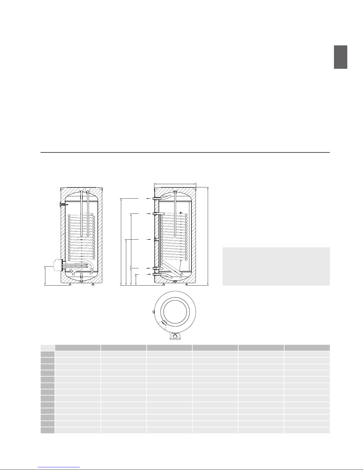
VLG 200 A1-1G VLG 200 A3-1G VLG 300 B1-1G VLG 300 B2-1G VLG 300 C1-1G VLG 400 C1-1G
A 1535 1675 1590 1590 1445 1915
B 180 220 175 175 250 250
C 300 340 270 270 370 370
D 880 1015 890 890 610 1070
G 780 945 740 740 800 990
H 1355 1435 1410 1410 1205 1675
I 365 405 320 340 400 400
J 580 680 680 680 760 760
1 G 3/4 G 3/4 G1 G1 G1 G1
2 G1 G1 G1 G 5/4 G 5/4 G 5/4
3 G 3/4 G 3/4 G 3/4 G 3/4 G 3/4 G 3/4
4 G1 G1 G1 G 5/4 G 5/4 G 5/4
5 G 3/4 G 3/4 G1 G1 G1 G1
5
4
3
2
1
øJ
I
H
A
G
C D
B
UGRADNJA
Cijenjeni kupci zahvaljujemo vam na kupovini našeg proizvoda.
MOLIMO DA PRIJE UGRADNJE I PRVE UPOTREBE SPREMNIKA TOPLE VODE
PAŽLJIVO PROČITATE UPUTE.
Spremnik je izrađen sukladno važećim standardima te službeno testiran, za istoga su izdani sigurnosni certifikati o
elektromagnetskoj kompatibilnosti. Osnovne tehničke karakteristike spremnika navedene su na natpisnoj pločici nalijepljenoj na
zaštitnom pokrovu.
Spremnik tople vode na vodovodnu i električnu mrežu smije priključiti samo za to osposobljen stručnjak. Zahvate u njegovoj
unutrašnjosti zbog popravaka, uklanjanja vodenog kamenca i provjere ili zamijene antikorozijske zaštitne anode može provoditi
samo ovlašteni serviser.
Spremnik tople vode izrađen je na način da se putem prijenosnika topline mogu koristiti sljedeći izvori grijanja, i to:
• kotao centralnog grijanja;
• sunčeva energija;
• toplinska crpka.
Spremnik tople vode postavite u suh prostor u kojem ne dolazi do zamrzavanja, po mogućnosti u blizinu drugih izvora energije
(npr. u ložionicu/kotlovnicu). Prije montaže zašarafite podesive nožice koje su priložene uz spremnik. Spremnik izravnajte uzdužno i
poprečno vrteći pritom podesive nožice.
Sl. 1: Priključne i montažne mjere spremnika (mm)
LEGENDA
1 Dotok hladne vode
2 Izlazak medija iz prijenosnika topline
3 Cirkulacijski vod
4 Ulazak medija u prijenosnik topline
5 Otjecanje tople vode
518362
3
HR/BIH
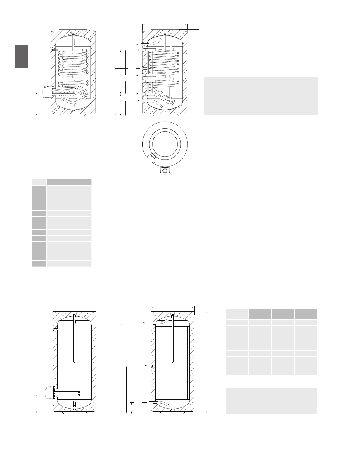
VLG 300 C1-2G
A 1445
B 250
C 370
D 740
G 800
H 1205
I 400
J 760
1 G1
2 G5/4
3 G 3/4
4 G5/4
5 G1
Sl. 2: Priključne i montažne mjere spremnika (mm)
5
4
3
2
1
øJ
I
H
A
G
C D
B
4
2
225 425
LEGENDA
1 Dotok hladne vode
2 Izlazak medija iz prijenosnika topline
3 Cirkulacijski vod
4 Ulazak medija u prijenosnik topline
5 Otjecanje tople vode
LEGENDA
1 Dotok hladne vode
3 Cirkulacijski vod
5 Otjecanje tople vode
1
3
5
B
G
H
I
A
øJ
VLG 200
A-G
VLG 300
B-G
VLG 400
B-G
A [mm] 1535 1590 1915
B [mm] 180 175 250
G [mm] 780 740 990
H [mm] 1355 1410 1675
I [mm] 365 320 400
J [mm] 580 680 760
1 G 3/4 G1 G1
3 G 3/4 G 3/4 G 3 /4
5 G 3/4 G1 G1
518362
4
HR/BIH
PRIKLJUČENJE NA VODOVODNU MREŽU
Priključenje na vodovodnu mrežu napravite prema uputama za priključenje iz prethodnog poglavlja.
Na dovodnu cijev, zbog jamčenja sigurnosti kod rada spremnika potrebno je ugraditi sigurnosni ventil ili sigurnosnu grupu koja
sprječava povećanje tlaka u kotlu za više od 0,1 MPa (1 bara) iznad nominalnog tlaka. Odvodni otvor na sigurnosnom ventilu
obavezno mora imati izlaz na atmosferski tlak. Kod grijanja vode u spremniku tlak vode u kotlu se povećava do granice koja je
namještena na sigurnosnom ventilu. Budući da je povratak vode u vodovodnu mrežu spriječen, može doći do kapanja vode iz
odvodnog otvora sigurnosnog ventila. Vodu koja kapa možete provesti u odvod putem prihvatnog nastavka koji namjestite ispod
sigurnosnog ventila. Odvodna cijev namještena ispod ispusta sigurnosnog ventila mora biti namještena u smjeru ravno prema dolje
te u okolini u kojoj ne dolazi do zamrzavanja.
U slučaju da želite izbjeći vodu koja kapa iz sigurnosnog ventila, morate na dovodnu cijev spremnika ugraditi ekspanzijsku posudu
za sanitarnu vodu volumena najmanje 5 % volumena spremnika.
Za pravilan rad sigurnosnog ventila potrebno je periodički provoditi kontrole radi uklanjanja vodenog kamenca te provjere
eventualne blokade sigurnosnog ventila. Prilikom kontrole morate pomakom ručke ili odšarafljivanjem matice ventila (ovisno od
tipa ventila) otvoriti istjecanje iz sigurnosnog ventila. Kod toga kroz sapnicu ventila za istjecanje mora isteći voda, što je znak da je
ventil u odličnom stanju.
Spremnik možete priključiti na kućnu vodovodnu mrežu bez regulatora tlaka ako je tlak u mreži niži od nominalnog tlaka (gledaj
natpisnu tablicu). U slučaju da je tlak u mreži viši od nominalnog, potrebno je ugraditi regulator tlaka.
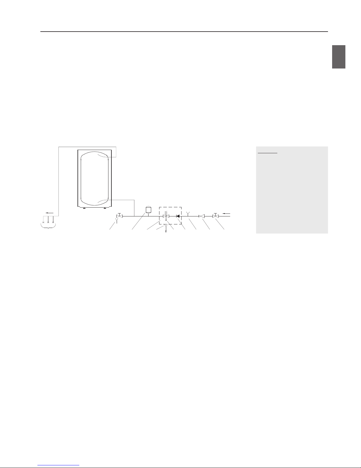
Sl. 3: Zatvoreni (tlačni) sistem
LEGENDA
1 Ispusni ventil
2 Ekspanzijska posuda
3 Sigurnosni ventil
a - Pokusni ventil
b - Nepovratni ventil
4 Čašica s priključkom na odvod
5 Pokusni nastavak
6 Redukcijski ventil tlaka
7 Zaporni ventil
8 Tlačne baterije za miješanje
H Hladna voda
T Topla voda
T
H
765ba43218
518362
5
HR/BIH
PRIKLJUČENJE NA ELEKTRIČNU MREŽU
Prije priključenja u električnu mrežu potrebno je u spremnik ugraditi priključnu uzicu minimalnog presjeka barem 1,5 mm2
(H05VV-F 3G 1,5 mm2) za 3kW grijač, u slučaju 6kW grijača (H05VV-F 5G 2,5 mm2), zato morate skinuti zaštitni poklopac.
To učinite na način da prvo izvučete gumb koji je umetnut na os termostata te odšarafite vijak.
Priprema za odvajanje svih polova mora biti ugrađena u elektroinstalaciji sukladno nacionalnim instalacijskim propisima.
Sl. 4: Uklanjanje pokrova grijača
Sl. 5: Sheme električkih instalacija
LEGENDA
1 Priključna spajalica
2 Termostat i dvopolni odnosno tropolni toplinski
osigurač
3 Grijač
L Fazni vodič
L1 Fazni vodič
L2 Fazni vodič
L3 Fazni vodič
N Neutralni vodič
Zaštitni vodič
L
230 V~
3F Y 230 V~
N
1
A
STB
+°C
+°C
TR
ΔT
B
1
R1 R2
R1 R2
R3 R4 R5 R6
R3
2
A1
STB
+°C
+°C
TR
ΔT
A2
B1
B2
A3 B3
2
3
1
2
3
L3
N
L1
L2
518362
6
HR/BIH

NAMIJEŠTANJE SONDI
Na gornjoj strani spremnika ispod pokrova postavljene su dvije cijevi za sonde gdje se mogu umetnuti sonde za regulaciju
sistemske povezanosti spremnika tople vode i drugih izvora grijanja. Maksimalni promjer sondi je 8 mm.
UPOZORENJE: Prije svakog zahvata u unutrašnjost spremnika, isti obavezno morate isključiti iz električne mreže!
Zahvat može provesti samo osposobljen stručnjak!
Sl. 6: Namještanje sondi
Duža cijev za sondu (donja pozicija kotla)
Kraća cijev za sondu (gornja pozicija kotla)
PRIKLJUČENJE NA DRUGE IZVORE GRIJANJA
Spremnik tople vode omogućava pripremu sanitarne vode putem izmjenjivača topline s različitim izvorima energije (npr. centralno
grijanje, sunčeva energija…).
Na skicama su prikazani primjeri spajanja spremnika tople vode s različitim izvorima grijanja.
Sl. 7: Spajanje sa solarnim konektorima Sl. 8: Spajanje s kotlom centralnog grijanja
LEGENDA
1 Spremnik tople vode
2 Kotao centralnog grijanja
3 Solarni kolektor
4 Diferencijalni termostat sa sondama
(T1, T2, T3, T4)
5 Cirkulacijska crpka
6 Ekspanzijska posuda
7 Nepovratni ventil
8 Sigurnosni ventil
9 Ventil za odzračivanje
10 Ventil za punjenje i pražnjenje sistema
11 Redukcijski ventil
12 Ispusni ventil
13 Zaporni ventil
14 Pokusni nastavak
15 Čašica s priključkom na odvod
1
4
6
3
9
15
12 8 7
14 11 13
10
5
7
8
T
1
T
2
1
T
1
T
3
5
4
15
12
12
87
7
2
9
141113
518362
7
HR/BIH

UPOTREBA I ODRŽAVANJE
Nakon priključenja na vodovodnu i električnu mrežu te druge izvore grijanja spremnik tople vode je spreman za upotrebu. Obično
je osnovni izvor grijanja sanitarne vode centralno grijanje ili sunčeva energija, pri čemu je regulacija grijanja tople vode provedena u
sistemu grijanja.
Ugrađen električni grijač namijenjen je samo za dodatno grijanje vode. Temperaturu regulirate vrtnjom gumba u smjeru kazaljke na
satu na željenu temperaturnu razinu.
- Zaštita od zamrzavanja, temperatura približno 10 °C
- Temperatura vode približno 35 °C.
- Temperatura vode približno 55 °C.
- Temperatura vode približno 85 °C.
Termometar prikazuje temperaturu na mjestu ugradnje, dok se vrtnjom gumba na termostatu regulira temperatura vode u donjem
dijelu spremnika. Zato može doči do razlika između te dvije temperature.
Kada postoji opasnost da dođe do zamrzavanja vode u spremniku, istu morate iz njega istočiti. Vodu iz spremnika ispraznite kroz
dolaznu cijev spremnika. U tu svrhu se preporuča da se između sigurnosnog ventila i dovodne cijevi ugradi T-član s ispusnim
ventilom. Prije pražnjenja spremnik treba isključiti iz električne mreže, zatvoriti dovod hladne vode u spremnik, otvoriti ručicu
za toplu vodu na priključenoj bateriji za miješanje te pričekati da se voda u spremniku ohladi. Nakon što se voda isprazni putem
dovodne cijevi, u spremniku ostane manja količina vode.
Vanjski dio spremnika čistite mekanom krpom i blagim tekućim sredstvima za čišćenje. Ne koristite sredstva za čišćenje koja sadrže
alkohol ili abrazivna sredstva.
Redovitim servisima osigurat ćete besprijekoran rad i dugi životni vijek spremnika. Garancija u slučaju hrđanja kotla vrijedi samo ako
ste provodili propisane redovite preglede istrošenosti zaštitne anode. Razdoblje među pojedinim redovitim pregledima ne smije biti
duže nego što je to navedeno u garancijskoj izjavi. Pregledi moraju biti izvedeni od strane ovlaštenog servisera koji vam pregled
evidentira u garancijskom listu proizvoda. Prilikom pregleda serviser provjeri istrošenost antikorozijske zaštitne anode i prema
potrebi očisti kamenac koji se s obzirom na kvalitetu, količinu i temperaturu potrošene vode nakupi u unutrašnjosti spremnika.
Serviser će vam nakon pregleda spremnika, s obzirom na utvrđeno stanje, preporučiti i datum sljedeće kontrole.
Molimo da mogući kvar na spremniku ne popravljate sami već da o njemu obavijestite najbližeg ovlaštenog
servisera.
518362
8
HR/BIH

TEHNIČKA SVOJSTVA UREĐAJA
Tip*
VLG 200
A1-1G
VLG 200
A3-1G
VLG 300
B1-1G
VLG 300
B2-1G
VLG 300
C1-1G
VLG 300
C1-2G
VLG 400
C1-1G
Razred energetske učinkovitosti
1)
C B C C B B B
Vlastiti gubitak S
2)
[W] 70,8 58,3 88,8 88,8 68 68 71,9
Korisni volumen [l] 184 190,3 275,5 262 283,7 283,7 396
Nominalni tlak [MPa (bar)] 0,6 (6); 0,9 (9); 1,0 (10)
Masa/napunjen vodom [kg] 97 / 281 115 / 305 140 / 416 165 / 427 165/449 170/454 230/626
Antikorozijska zaštita kotla
Emajlirano/Mg anoda
• / • • / • • / • • / • • / • • / • • / •
Razred zaštite I
Stupanj zaštite IP24
Površina prijenosnika topline [m2] 2,0 2,3 2,5 4,0 3,45 1,05 + 2,4 6,15
Temperatura grijaćeg medija u
prijenosniku topline
[°C] < 95
Debljina izolacije [mm] 60 110 67 67 75 75 75
Toplinski gubici
2)
[kWh/24h] 1,7 1,4 2,1 2,1 1,6 1,6 1,7
Maksimalni promjer sondi [mm] ø8
Model
VLG 200
A1-1G3
VLG 200
A3-1G3
VLG 300
B1-1G3
VLG 300
B2-1G3
VLG 300
B1-1G6
VLG 300
B2-1G6
Potrošnja struje [W] 3000 6000
Napon [V~] 230 400
Model
VLG 300
C1-1G3
VLG 300
C1-2G3
VLG 400
C1-1G3
VLG 300
C1-1G6
VLG 300
C1-2G6
VLG 400
C1-1G6
Potrošnja struje [W] 3000 6000
Napon [V~] 230 400
* Ako u tipskoj oznaci nema slova G, aparat je bez električnog grijača
1)
Uredba komisije EU 812/2013
2)
Testirano po EN 12897:2006
PRIDRŽAVAMO PRAVA NA PROMJENE KOJE NE UTJEČU NA FUNKCIONALNOST APARATA.
Upute za korištenje dostupne su na našim web stranicama http://www.gorenje.com.
1)
direktiva 812/2013; EN 50440
2)
EN 50440
3)
Testirano po SIST EN 60379:2005
Tipovi
VLG 200 A-G VLG 300 B-G VLG 400 C-G
Profil uporabe
XL XL XL
Razred energetske učinkovitosti
1)
C C C
Energetska učinkovitost grijanja vode ƞwh
1)
[%] 38,1 38,0 38,1
Godišnja potrošnja električne energije
1)
[kWh] 4399 4412 4400
Dnevna potrošnja električne energije
2)
[kWh] 20,317 20,397 20,328
Podešena temperatura termostata
"eco" "eco" "eco"
Moguće sigurnosne mjere
(sastav, postavljanje, održavanje)
Kod tlačnog priključenja obvezna uporaba sigurnosnog ventila.
Vrijednost smart
0 0 0
Zapremina
[l] 203 319 449
Miješana voda na 40°C V40
2)
[l] 305 508 712
Nominalni tlak
[MPa (bar)] 0,6 (6); 0,9 (9); 1,0 (10)
Masa/napunjen vodom
[kg] 63/265 97/397 230/626
Antikorozijska zaštita kotla
Emajlirano/Mg anoda
• / • • / • • / •
Razred zaštite
I
Stupanj zaštite
IP24
Debljina izolacije
[mm] 60 67 75
Toplinski gubici
3)
[kWh/24h] 1,7 2,1 1,7
Vrijeme zagrijavanja od 10 °C do 65 °C
[h] 4
25
6
56
4
53
Model
VLG 200 A-G3 VLG 300 B-G3 VLG 400 C-G6
Potrošnja struje
[W] 3000 6000
Napon
[V~] 230 400
518362
9
HR/BIH

Our products incorporate components that are both environmentally safe and harmless to health, so they can
be disassembled as easily as possible and recycled once they reach their final life stage.
Recycling of materials reduces the quantity of waste and the need for production of raw materials (e.g. metals)
which requires a substantial amount of energy and causes release of harmful substances. Recycling procedures
reduce the consumption of natural resources, as the waste parts made of plastic and metal can be returned to
various production processes.
For more information on waste disposal, please visit your waste collection centre or the store where the
product was purchased
The appliance may be used by children aged 8 and older and persons with physical, sensory or mental
disabilities or lacking experience or knowledge, if they are under supervision or taught about safe use of the
appliance and if they are aware of the potential dangers.
Children should not play with the appliance.
Children should not clean or maintain the appliance without supervision
The installation should be performed in accordance with the valid regulations and the instructions of the
manufacturer. It should be performed by a professionally trained installation expert.
It is obligatory to install a safety valve with a rated pressure of 0.6 MPa (6 bar), 0.9 MPa (9 bar) or 1.0 MPa (10
bar) – see the label - on the inlet pipe of the hot water storage tank to prevent the elevation of pressure in the
tank by more than 0.1 MPa (1 bar) above the rated pressure.
Water may drip from the outlet opening of the safety valve, so the outlet opening should be set to atmospheric
pressure.
The outlet of the safety valve should be installed facing downwards and in a non-freezing area.
To ensure proper functioning of the safety valve, the user should perform regular controls to remove limescale
and make sure the safety valve is not blocked.
Do not install a stop valve between the hot water storage tank and the safety valve, because it will impair the
pressure protection of the storage tank!
Before connecting the heater to the power supply, the storage tank must be filled with water!
The storage tank is protected in case of failure of the operating thermostat with an additional thermal cut-out.
In case of thermostat failure water in the storage tank may reach the temperature of up to 130°C in accordance
with safety standards. The possibility of such temperature overload should be taken into consideration in the
execution of plumbing.
Should you choose to disconnect the power, the storage tank should be drained thoroughly before the onset of
freezing conditions.
Water from the storage tank is drained through the inlet pipe of the tank. For this purpose, a special fitting
(T-fitting) with an outlet valve must be mounted between the safety valve and the inlet pipe.
Please do not try to fix any defects of the storage tank on your own. Call the nearest authorised service provider.
WARNINGS
518362
10
EN

5
4
3
2
1
øJ
I
H
A
G
C D
B
INSTALLATION
Dear buyer, thank you for purchasing our product.
PRIOR TO THE INSTALLATION AND FIRST USE OF THE HOT WATER STORAGE
TANK, PLEASE READ THESE INSTRUCTIONS CAREFULLY.
This storage tank has been manufactured in compliance with the relevant Standards and tested by the relevant authorities as
indicated by the Safety Certificate and the Electromagnetic Compatibility Certificate. The technical characteristics of the product
are listed on the label attached to the protective cover.
The connection of the storage tank to the plumbing and power networks must be carried out by qualified staff only. All repairs
and maintenance work in the interior of the storage tank, as well as limestone removal or testing or replacement of the corrosion
protection anode, may only be carried out by an approved maintenance service provider.
The hot water storage tank is designed in a manner which allows using the following heating sources, via a heat exchanger:
• Central heating hot-water system,
• Solar power,
• Heating pump.
The heater should be installed in a dry room that is not subject to freezing conditions, preferably in the vicinity of other sources
of heating (e.g. boiler room). Prior to installation screw on the enclosed adjustable legs. Level the storage tank longitudinally and
transversally by rotating the adjustable legs.
Image 1: Connection and installation dimensions of the storage tank [mm]
KEY
1 Cold water inflow
2 Medium outlet from the heat exchanger
3 Circulation conduit
4 Medium inflow into the heat exchanger
5 Hot water outflow
VLG 200 A1-1G VLG 200 A3-1G VLG 300 B1-1G VLG 300 B2-1G VLG 300 C1-1G VLG 400 C1-1G
A 1535 1675 1590 1590 1445 1915
B 180 220 175 175 250 250
C 300 340 270 270 370 370
D 880 1015 890 890 610 1070
G 780 945 740 740 800 990
H 1355 1435 1410 1410 1205 1675
I 365 405 320 340 400 400
J 580 680 680 680 760 760
1 G 3/4 G 3/4 G1 G1 G1 G1
2 G1 G1 G1 G 5/4 G 5/4 G 5/4
3 G 3/4 G 3/4 G 3/4 G 3/4 G 3/4 G 3/4
4 G1 G1 G1 G 5/4 G 5/4 G 5/4
5 G 3/4 G 3/4 G1 G1 G1 G1
518362
11
EN

VLG 300 C1-2G
A 1445
B 250
C 370
D 740
G 800
H 1205
I 400
J 760
1 G1
2 G5/4
3 G 3/4
4 G5/4
5 G1
Image 2: Connection and installation dimensions of the storage tank [mm]
5
4
3
2
1
øJ
I
H
A
G
C D
B
4
2
225 425
KEY
1 Cold water inflow
2 Medium outlet from the heat exchanger
3 Circulation conduit
4 Medium inflow into the heat exchanger
5 Hot water outflow
KEY
1 Cold water inflow
3 Circulation conduit
5 Hot water outflow
1
3
5
B
G
H
I
A
øJ
VLG 200
A-G
VLG 300
B-G
VLG 400
B-G
A [mm] 1535 1590 1915
B [mm] 180 175 250
G [mm] 780 740 990
H [mm] 1355 1410 1675
I [mm] 365 320 400
J [mm] 580 680 760
1 G 3/4 G1 G1
3 G 3/4 G 3/4 G 3 /4
5 G 3/4 G1 G1
518362
12
EN

CONNECTION TO THE WATER SUPPLY
Connection to water supply should be made according to the markings for the connections, as defined in the previous Chapter.
For safety reasons the supply pipe must be fitted with a safety valve or, alternatively, a valve of the safety class that prevents the
pressure in the tank from exceeding the nominal pressure by more than 0.1 MPa (1 bar). The outlet opening on the safety valve
must be equipped with an outlet for atmospheric pressure. The heating of water in the storage tank causes the pressure in the tank
to increase to the level set by the safety valve. As the water cannot return to the water supply system, this can result in dripping
from the outlet opening of the safety valve. The drip can be piped to a drain by installing a catching unit just below the safety
valve. The drain installed below the safety valve outlet must be piped down vertically and placed in an environment that is free
from the onset of freezing conditions.
In case you want to avoid water dripping from the safety valve, an expansion tank for domestic water with at least 5 % of the
volume of the storage tank should be installed on the inlet pipe of the storage tank.
To ensure proper functioning of the safety valve, the user should perform regular controls to remove limescale and make sure the
safety valve is not blocked. To check the valve, open the outlet of the safety valve by turning the handle or unscrewing the nut of the
valve (depending on the type of valve). The valve is operating properly if the water comes out of the nozzle when the outlet is open.
The storage tank can be connected to the domestic water supply network without a pressure regulator if the pressure in the
network is lower than the nominal pressure (see the label). If the pressure in the network exceeds the nominal pressure, a pressure
regulator must be installed.
Image 3: Closed (pressure) system
KEY
1 Drain valve
2 Expansion tank
3 Safety valve
a - Test valve
b - Non-return valve
4 Funnel outlet to the drain
5 Test unit
6 Pressure-reducing valve
7 Stop valve
8 Pressure mixer taps
H Cold water
T Hot water
T
H
765ba43218
518362
13
EN

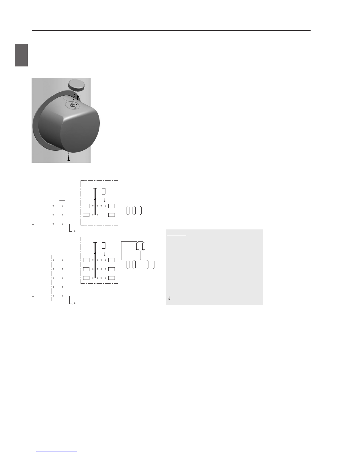
CONNECTION TO THE POWER SUPPLY NETWORK
Before connecting the storage tank to the power supply network, a connection cable with a minimum cross-section of at least
1.5 mm2 (H05VV-F 3G 1.5 mm2) for a 3kW-heating element and 2.5 mm2 for a 6kW-heating element (H05VV-F 5G 2,5 mm2) must be
installed in it and the protection cover must be removed.
This is done by pulling out the knob on the thermostat axis and unscrewing two screws.
An all-pole disconnect device must be installed in the electric installation to comply with the National Installation Regulations.
Image 4: Removal of heater cover
Image 5: Schemes of electric installations
KEY
1 Connection terminal
2 A thermostat and a bipolar or tripolar thermal
cut-out
3 Heater
L Live conductor
L1 Live conductor
L2 Live conductor
L3 Live conductor
N Neutral conductor
Earthing conductor
L
230 V~
3F Y 230 V~
N
1
A
STB
+°C
+°C
TR
ΔT
B
1
R1 R2
R1 R2
R3 R4 R5 R6
R3
2
A1
STB
+°C
+°C
TR
ΔT
A2
B1
B2
A3 B3
2
3
1
2
3
L3
N
L1
L2
518362
14
EN

INSTALLATION OF SENSORS
On the upper side of the storage tank there are two sensor tubes for mounting the sensors for regulation of the system connection
of the hot water storage tank to other heating sources. The maximum diameter of the sensors is 8 mm.
WARNING: Before any intervention into the interior of the storage tank disconnect it from the power supply! All
interventions must be carried out by qualified staff only!
Image 6: Installation of sensors
Long sensor tube (lower tank position)
Short sensor tube (upper tank position)
CONNECTION TO ALTERNATIVE
SOURCES OF HEATING
The hot water storage tank enables the water for sanitary use to be heated by alternative sources of energy (e.g. central heating,
solar power etc.) by installing a Heat Exchanger.
Examples of connecting the hot water storage tank to various sources of heating are shown in the drawings below.
Image 7: Connection to solar panels Image 8: Connection to the central heating hot-water system
KEY
1 Hot water storage tank
2 Central heating hot-water system
3 Solar panel
4 Differential thermostat with sensors
(T1, T2, T3, T4)
5 Bypass pump
6 Expansion tank
7 Non-return valve
8 Safety valve
9 Air relief valve
10 Fill/drain valve
11 Reduction valve
12 Drain valve
13 Stop valve
14 Test unit
15 Funnel outlet to the drain
1
4
6
3
9
15
12 8 7
14 11 13
10
5
7
8
T
1
T
2
1
T
1
T
3
5
4
15
12
12
87
7
2
9
141113
518362
15
EN

USE AND MAINTENANCE
The hot water storage tank is ready for use once it has been connected to water and electricity and other heating sources. The
usual main sources for heating domestic water are central heating or solar power; in this case any regulation of water heating is
performed in the heating system.
The built-in electric heating element is designed for backup heating of water only. The temperature is set by turning the knob in a
clockwise direction to reach the desired temperature level.
- Protection against freezing, temperature around 10 °C.
- Water temperature around 35 °C.
- Water temperature around 55 °C.
- Water temperature around 85 °C.
The thermometer shows the in-situ temperature, whereas by turning the knob on the thermostat the water temperature in the
lower part of the storage tank is set. Thus, these two temperatures may vary.
In case of exposure to sub-zero temperatures, the water should be drained from the storage tank thoroughly before the onset of
freezing conditions. Water from the storage tank is drained through the inlet pipe of the storage tank. For this purpose, a special
fitting (T-fitting) with an outlet valve must be mounted between the safety valve and the inlet pipe. Before discharge make sure the
storage tank is disconnected from the power supply, close the inlet of cold water into the storage tank, open the hot water tap on
the connected mixer tap and wait for the water in the storage tank to cool down. After discharging through the inlet pipe there is
still some water left in the storage tank.
The external parts of the water heater may be cleaned with a soft cloth and mild cleaning fluids. Do not use cleaning fluids
containing alcohol or abrasives.
Regular preventive maintenance inspections ensure faultless performance and long life of your storage tank. Tank Warranty is
subject to regular inspections of the wear of the protective anode. The period between individual regular inspections should not be
longer than specified in the Guarantee statement. Inspection should be carried out by an authorised maintenance service provider
recording the inspection on the Guarantee Certificate of the product. During the inspection, the wear of the corrosion protection
anode will be inspected and any limestone built up in the interior of the storage tank, depending on the quality, quantity and
temperature of used water, will be removed as required. After inspecting the storage tank, the maintenance service provider will
also recommend the date of the next inspection according to the ascertained status.
Please do not try to fix any defects of the storage tank on your own. Call the nearest authorised service provider.
518362
16
EN

Type *
VLG 200
A1-1G
VLG 200
A3-1G
VLG 300
B1-1G
VLG 300
B2-1G
VLG 300
C1-1G
VLG 300
C1-2G
VLG 400
C1-1G
Energy efficiency class
1)
C B C C B B B
Standing loss S
2)
[W] 70,8 58,3 88,8 88,8 68 68 71,9
Storage volume [l] 184 190,3 275,5 262 283,7 283,7 396
Rated pressure [MPa (bar)] 0,6 (6); 0,9 (9); 1,0 (10)
Weight/filled with water [kg] 97 / 281 115 / 305 140 / 416 165 / 427 165/449 170/454 230/626
Anti-corrosion protection of tank
Enamelled/Mg anode
• / • • / • • / • • / • • / • • / • • / •
Protection class I
Degree of protection IP24
Heat exchanger surface [m2] 2,0 2,3 2,5 4,0 3,45 1,05 + 2,4 6,15
Temperature of the heating medium
in the heat exchanger
[°C] < 95
Insulation thickness [mm] 60 110 67 67 75 75 75
Heat loss
2)
[kWh/24h] 1,7 1,4 2,1 2,1 1,6 1,6 1,7
Maximum diameter of sensors [mm] ø8
Model
VLG 200
A1-1G3
VLG 200
A3-1G3
VLG 300
B1-1G3
VLG 300
B2-1G3
VLG 300
B1-1G6
VLG 300
B2-1G6
Connected load [W] 3000 6000
Voltage [V~] 230 400
Model
VLG 300
C1-1G3
VLG 300
C1-2G3
VLG 400
C1-1G3
VLG 300
C1-1G6
VLG 300
C1-2G6
VLG 400
C1-1G6
Connected load [W] 3000 6000
Voltage [V~] 230 400
* If there is no letter G in the type designation, the appliance does not include the electric heater.
1)
Commission Regulation EU 812/2013
2)
Tested pursuant to EN 12897:2006
TECHNICAL CHARACTERISTICS OF THE APPLIANCE
WE RESERVE THE RIGHT TO ANY MODIFICATIONS NOT AFFECTING THE FUNCTIONALITY OF THE APPLIANCE.
The instructions for use are also available on our website http://www.gorenje.com.
1)
directive 812/2013; EN 50440
2)
EN 50440
3)
Tested pursuant to SIST EN 60379:2005
Type
VLG 200 A-G VLG 300 B-G VLG 400 C-G
Use profile
XL XL XL
Energy eciency class
1)
C C C
Energy eciency of water heating ƞwh
1)
[%] 38,1 38,0 38,1
Annual electrical energy consumption
1)
[kWh] 4399 4412 4400
Daily electrical energy consumption
2)
[kWh] 20,317 20,397 20,328
Set thermostat temperature
"eco" "eco" "eco"
Potential safety measures
(assembly, installation, maintenance)
Compulsory use of a safety valve with the pressure connection.
Smart value
0 0 0
Storage volume
[l] 203 319 449
Mixed water at 40 °C V40 2)
[l] 305 508 712
Rated pressure
[MPa (bar)] 0,6 (6); 0,9 (9); 1,0 (10)
Weight/filled with water
[kg] 63/265 97/397 230/626
Anti-corrosion protection of tank
Enamelled/Mg anode
• / • • / • • / •
Protection class
I
Degree of protection
IP24
Insulation thickness
[mm] 60 67 75
Heat loss
3)
[kWh/24h] 1,7 2,1 1,7
Heating time from 10 °C to 65 °C
[h] 4
25
6
56
4
53
Model
VLG 200 A-G3 VLG 300 B-G3 VLG 400 C-G6
Connected load
[W] 3000 6000
Voltage
[V~] 230 400
518362
17
EN

518362
18

518362
19

VLG 200 - 400 05/2017
518362
 Loading...