

Gorenje VLG 300 C1-1G6, VLG 300 B1-1G3, VLG 200 A3-1G3, VLG 300 C1-2G3, VLG 300 B2-1G3 Instructions For Use Manual
...
VLG 200 - 400
NAVODILO ZA UPORABO
INSTRUCTIONS FOR USE
SLEN
www.gorenje.com
OPOZORILA
Aparat lahko uporabljajo otroci stari 8 let in starejši in osebe z zmanjšanimi fizičnimi, čutnimi ali mentalnimi
sposobnostmi ali s pomanjkanjem izkušenj oz. znanjem če so pod nadzorom ali poučeni glede uporabe aparata
SL
na varen način in da razumejo možne nevarnosti.
Otroci se ne smejo igrati z aparatom.
Čiščenje in vzdrževanje aparata ne smejo izvajati otroci brez nadzora.
Vgradnja mora biti izvedena v skladu z veljavnimi predpisi in po navodilih proizvajalca. Izvesti jo mora strokovno
usposobljen monter.
Na dotočno cev hranilnika tople vode je potrebno obvezno vgraditi varnostni ventil z nazivnim tlakom 0,6 MPa
(6 bar), 0,9 MPa (9 bar) ali 1,0 MPa (10 bar) (glejte napisno tablico), ki preprečuje zvišanje tlaka v kotlu za več
kot
0,1 MPa (1 bar) nad nazivnim.
Voda lahko kaplja iz odtočne odprtine varnostnega ventila zato mora biti odtočna odprtina odprta na
atmosferski tlak.
Izpust varnostnega ventila mora biti nameščen v smeri navzdol in v območju, kjer ne zamrzuje.
Za pravilno delovanje varnostnega ventila je potrebno periodično izvajati kontrole, da se odstrani vodni kamen in
se preveri, da varnostni ventil ni blokiran.
Med hranilnik tople vode in varnostni ventil ni dovoljeno vgraditi zapornega ventila, ker s tem onemogočite
tlačno varovanje hranilnika!
Pred električno priključitvijo grelca je potrebno hranilnik obvezno najprej napolniti z vodo!
Hranilnik je zaščiten za primer odpovedi delovnega termostata z dodatno toplotno varovalko. V primeru
odpovedi termostata lahko v skladu z varnostnimi standardi voda v hranilniku doseže temperaturo tudi do
130 °C. Pri izvedbi vodovodnih inštalacij je obvezno potrebno upoštevati, da lahko pride do navedenih
temperaturnih preobremenitev.
Če boste hranilnik iz električnega omrežja izklopili, morate ob nevarnosti zamrznitve vodo iz njega iztočiti.
Voda iz hranilnika se izprazni skozi dotočno cev kotla. V ta namen je priporočljivo med varnostni ventil in
dotočno cev namestiti poseben T-člen z izpustnim ventilom.
Prosimo Vas, da morebitnih okvar na hranilniku ne popravljate sami, ampak o njih obvestite najbližjo
pooblaščeno servisno službo.
518375
Naši izdelki so opremljeni z okolju in zdravju neškodljivimi komponentami in so izdelani tako, da jih lahko v
njihovi zadnji življenjski fazi čim bolj enostavno razstavimo in recikliramo.
Z reciklažo materialov zmanjšujemo količine odpadkov in zmanjšamo potrebo po proizvodnji osnovnih
materialov (na primer kovine), ki zahteva ogromno energije ter povzroča izpuste škodljivih snovi. Z reciklažnimi
postopki tako zmanjšujemo porabo naravnih virov, saj lahko odpadne dele iz plastike in kovin ponovno vrnemo
v različne proizvodne procese.
Za več informacij o sistemu odlaganja odpadkov obiščite svoj center za odlaganje odpadkov, ali trgovca, pri
katerem je bil izdelek kupljen.
2
Cenjeni kupec, zahvaljujemo se Vam za nakup našega izdelka.
øJ
I
PROSIMO, DA PRED VGRADNJO IN PRVO UPORABO HRANILNIKA TOPLE VODE
SKRBNO PREBERETE NAVODILA.
Hranilnik je izdelan v skladu z veljavnimi standardi in uradno preizkušen, zanj pa sta bila izdana varnostni certifikat in certifikat
o elektromagnetni kompatibilnosti. Njegove osnovne tehnične lastnosti so navedene na napisni tablici, nalepljeni na zaščitnem
pokrovu.
Hranilnik sme priključiti na vodovodno in električno omrežje le za to usposobljen strokovnjak. Posege v njegovo notranjost zaradi
popravila, odstranitve vodnega kamna ter preverjanja ali zamenjave protikorozijske zaščitne anode lahko opravi samo pooblaščena
servisna služba.
Hranilnik tople vode je izdelan tako, da lahko preko toplotnega prenosnika uporabljamo sledeče vire ogrevanja in sicer:
• kotel centralnega ogrevanja,
• sončno energijo,
• toplotno črpalko.
VGRADNJA
Hranilnik tople vode postavite v suh prostor, kjer ne zmrzuje, po možnosti v bližino drugih virov ogrevanja (npr. v kurilnico). Pred
postavitvijo privijačite priložene nastavljive nogice. Hranilnik izravnajte vzdolžno in prečno z vrtenjem nastavljivih nogic.
5
4
SL
H
G
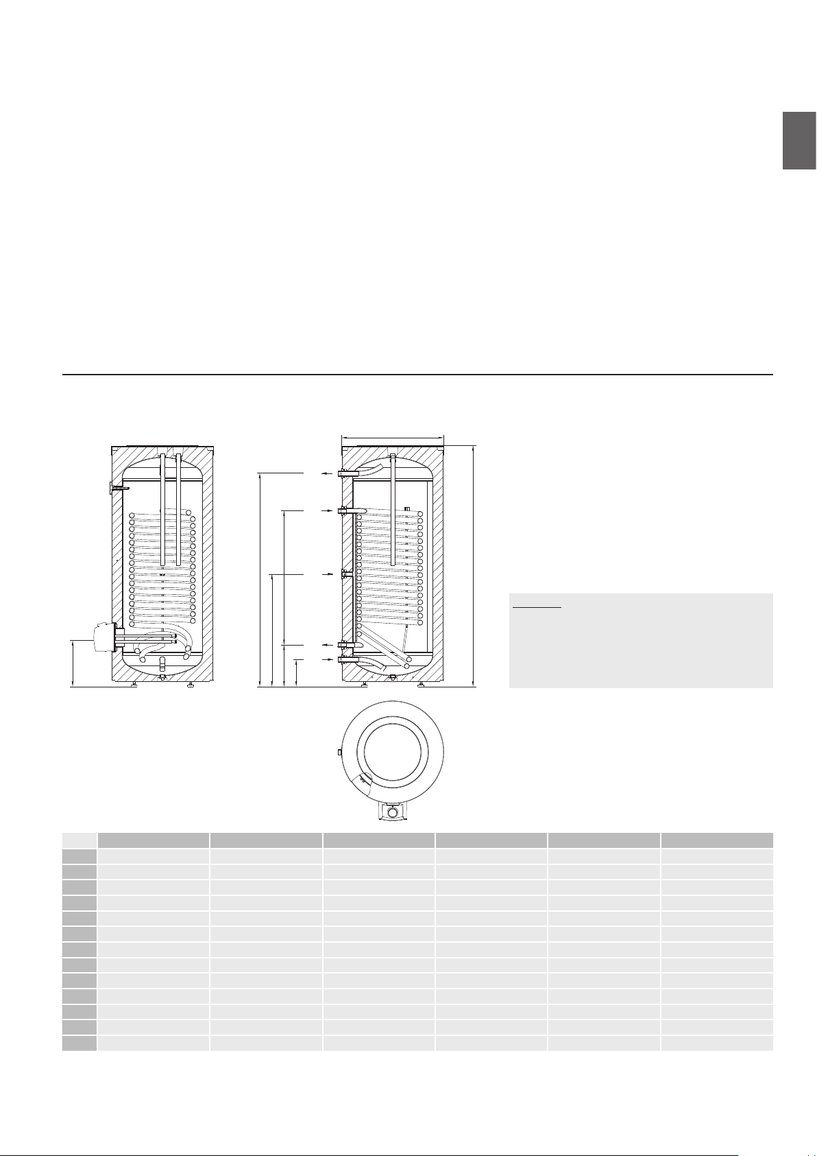
VLG 200 A1-1G VLG 200 A3-1G VLG 300 B1-1G VLG 300 B2-1G VLG 300 C1-1G VLG 400 C1-1G
A 1535 1675 1590 1590 1445 1915
B 180 220 175 175 250 250
C 300 340 270 270 370 370
D 880 1015 890 890 610 1070
G 780 945 740 740 800 990
H 1355 1435 1410 1410 1205 1675
I 365 405 320 340 400 400
J 580 680 680 680 760 760
1 G 3/4 G 3/4 G1 G1 G1 G1
2 G1 G1 G1 G 5/4 G 5/4 G 5/4
3 G 3/4 G 3/4 G 3/4 G 3/4 G 3/4 G 3/4
4 G1 G1 G1 G 5/4 G 5/4 G 5/4
5 G 3/4 G 3/4 G1 G1 G1 G1
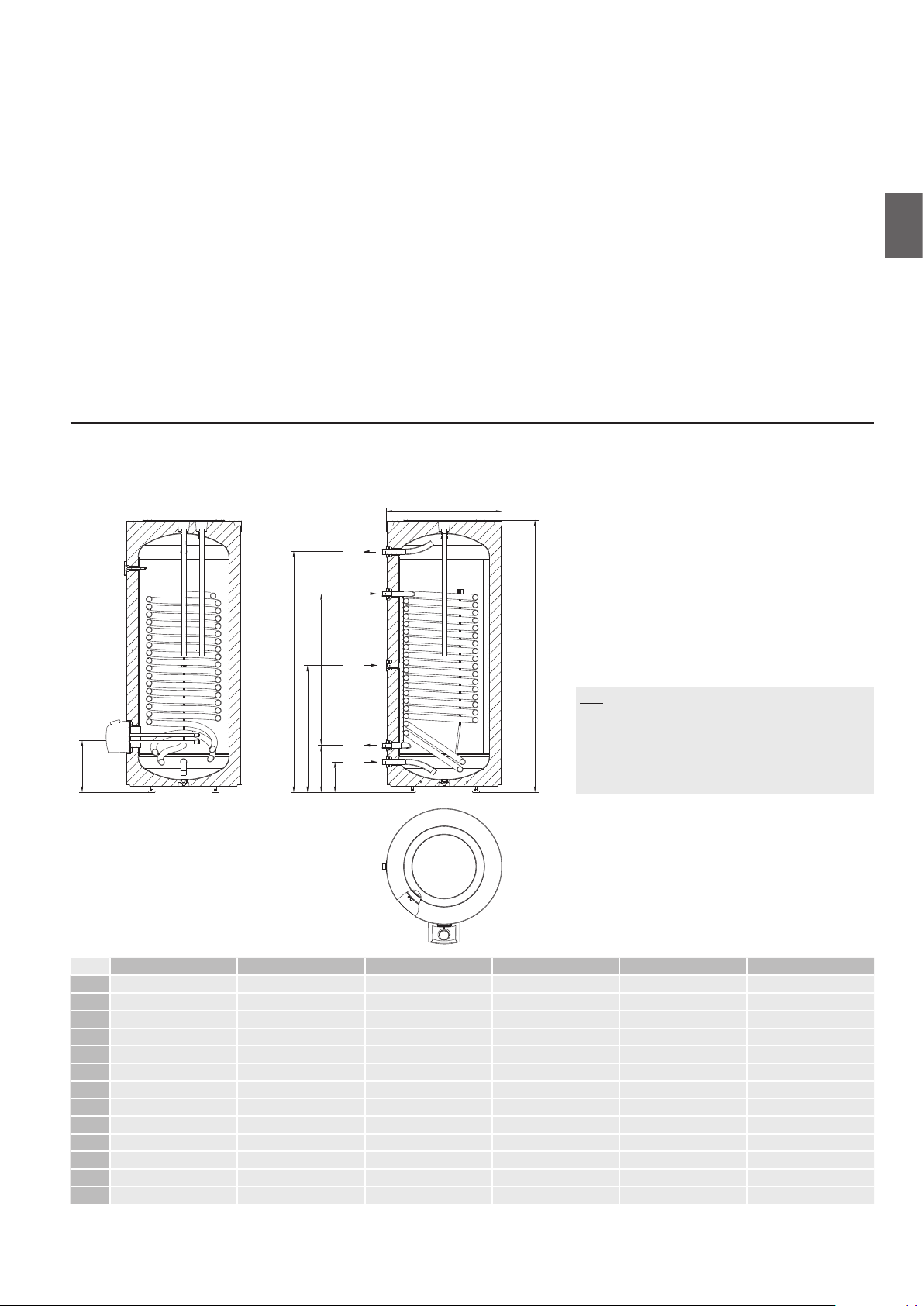
Sl. 1: Priključne in montažne mere hranilnika [mm]
3
2
1
C D
B
A
LEGENDA
1 Dotok hladne vode
2 Izstop medija iz prenosnika toplote
3 Cirkulacijski vod
4 Vstop medija v prenosnik toplote
5 Odtok tople vode
3
518375
I
I
SL
øJ
5
4
H
G
C D
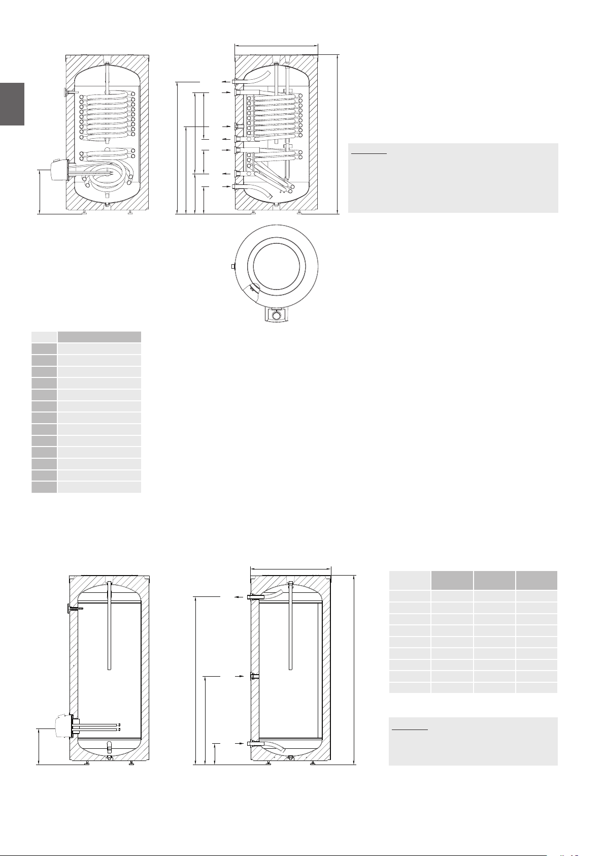
VLG 300 C1-2G
A 1445
B 250
C 370
D 740
G 800
H 1205
I 400
J 760
1 G1
2 G5/4
3 G 3/4
4 G5/4
5 G1
Sl. 2: Priključne in montažne mere hranilnika [mm]
225 425
B
3
2
4
A
LEGENDA
1 Dotok hladne vode
2
1
2 Izstop medija iz prenosnika toplote
3 Cirkulacijski vod
4 Vstop medija v prenosnik toplote
5 Odtok tople vode
518375
øJ
VLG 200
A-G
5
A [mm] 1535 1590 1915
VLG 300
B-G
VLG 400
B-G
B [mm] 180 175 250
G [mm] 780 740 990
H [mm] 1355 1410 1675
I [mm] 365 320 400
J [mm] 580 680 760
H
3
A
1 G 3/4 G1 G1
3 G 3 /4 G 3/4 G 3/4
5 G 3 /4 G1 G1
G
1
B
LEGENDA
1 Dotok hladne vode
3 Cirkulacijski vod
5 Odtok tople vode
4

PRIKLJUČITEV NA VODOVODNO OMREŽJE
765ba43218
Priključitev na vodovodno omrežje napravite po označbah za priključke iz predhodnega poglavja.
Na dotočno cev je zaradi zagotavljanja varnosti pri delovanju hranilnika potrebno vgraditi varnostni ventil ali varnostno grupo,
ki preprečuje zvišanje tlaka v kotlu za več kot 0,1 MPa (1 bar) nad nazivnim. Iztočna odprtina na varnostnem ventilu mora imeti
obvezno izhod na atmosferski tlak. Pri segrevanju vode v hranilniku se tlak vode v kotlu zvišuje do meje, ki je nastavljena v
varnostnem ventilu. Ker je vračanje vode nazaj v vodovodno omrežje preprečeno, lahko pride do kapljanja vode iz odtočne
odprtine varnostnega ventila. Kapljajočo vodo lahko speljete v odtok preko lovilnega nastavka, ki ga namestite pod varnostni ventil.
Odtočna cev nameščena pod izpustom varnostnega ventila mora biti nameščena v smeri naravnost navzdol in v okolju, kjer ne
zmrzuje.
V primeru, da se želite izogniti kapljajoči vodi iz varnostnega ventila, morate na dotočno cev hranilnika vgraditi ekspanzijsko
posodo za sanitarno vodo volumna najmanj 5% volumna hranilnika.
Za pravilno delovanje varnostnega ventila je potrebno periodično izvajati kontrole, da se odstrani vodni kamen in se preveri, da
varnostni ventil ni blokiran. Ob preverjanju morate s premikom ročke ali odvitjem matice ventila (odvisno od tipa ventila) odpreti
iztok iz varnostnega ventila. Pri tem mora skozi iztočno odprtino ventila priteči voda, kar je znak, da je ventil brezhiben.
LEGENDA
1 Izpustni ventil
2 Ekspanzijska posoda
3 Varnostni ventil
a - Preizkusni ventil
b - Nepovratni ventil
4 Lijak s priključkom na odtok
5 Preizkusni nastavek
6 Redukcijski ventil tlaka
T
H
7 Zaporni ventil
8 Tlačne mešalne baterije
SL
H Hladna voda
T Topla voda
Sl. 3: Zaprti (tlačni) sistem
Hranilnik lahko priključite na hišno vodovodno omrežje brez regulatorja tlaka, če je tlak v omrežju nižji od nazivnega tlaka (glejte
napisno tablico). Če tlak v omrežju presega nazivni tlak, je potrebno obvezno vgraditi regulator tlaka.
5
518375
PRIKLJUČITEV NA ELEKTRIČNO OMREŽJE
L
230 V~
3F Y 230 V~
N
2
L3
N
L1
L2
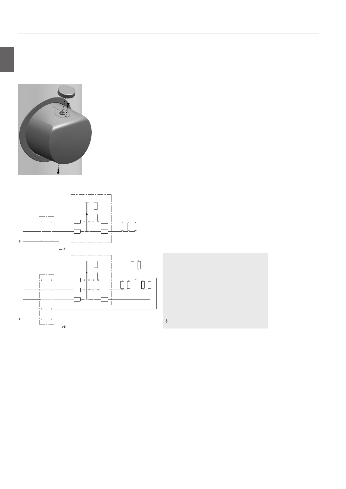
Pred priključitvijo v električno omrežje je potrebno v hranilnik vgraditi priključno vrvico minimalnega preseka vsaj 1,5 mm2
(H05VV-F 3G 1,5 mm2) za 3kW grelo, v primeru 6kW grela (H05VV-F 5G 2,5 mm2), zato morate odstraniti zaščitni pokrov.
To storite tako, da najprej izvlečete gumb, ki je vstavljen na os termostata in odvijete vijaka.
SL
Priprava za ločitev vseh polov mora biti vgrajena v električni inštalaciji v skladu z nacionalnimi inštalacijskimi predpisi.
Sl. 4: Odstranitev pokrova grelca
1
1
Sl. 5: Sheme električnih vezav
STB
TR
ΔT
+°C
+°C
A
B
2
STB
TR
ΔT
+°C
+°C
A1
A2
A3 B3
R1 R2
3
R3
1
2
LEGENDA
R1 R2
1 Priključna sponka
2 Termostat in dvopolna oz. tripolna varovalka
B1
B2
R3 R4 R5 R6
3
3 Grelec
L Fazni vodnik
L1 Fazni vodnik
L2 Fazni vodnik
L3 Fazni vodnik
N Nevtralni vodnik
Zaščitni vodnik
518375
6
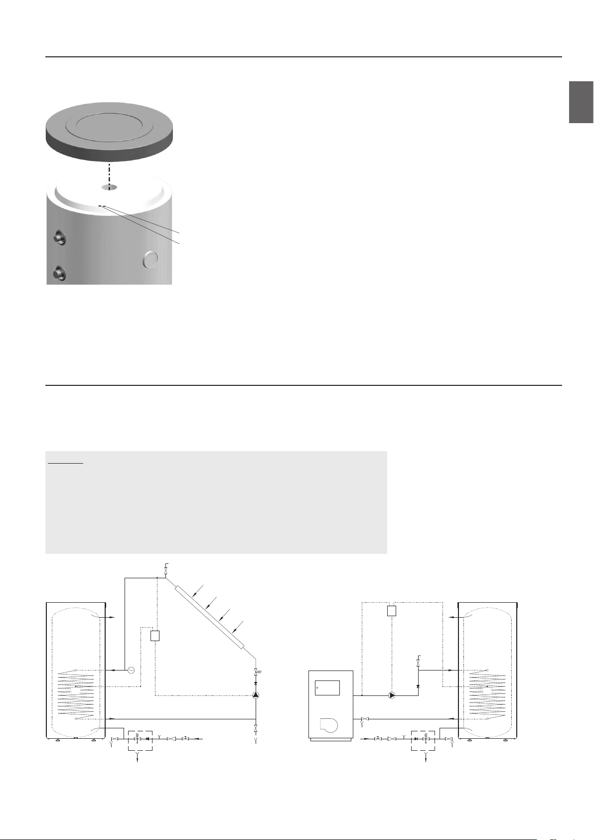
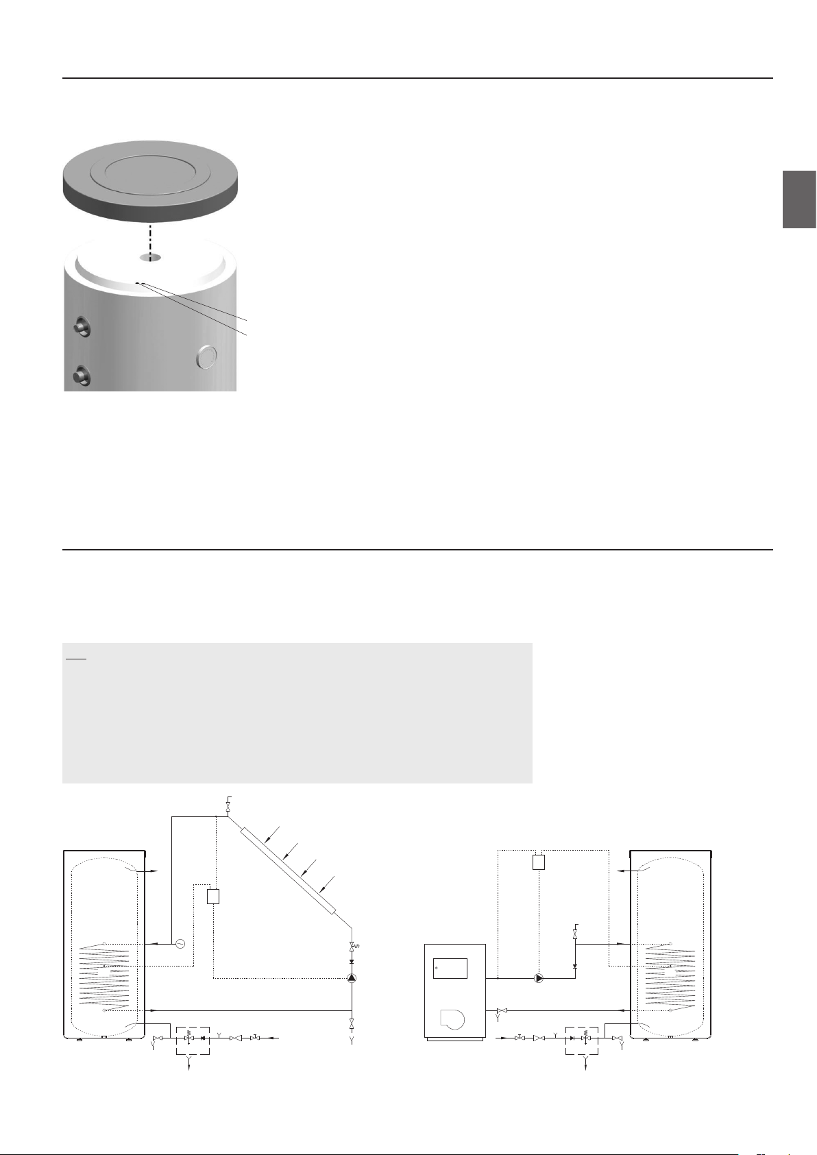
NAMESTITEV TIPAL
Na zgornji strani hranilnika pod pokrovom sta nameščeni dve cevi za tipala, kjer se lahko vstavijo tipala za regulacijo sistemske
povezave hranilnika tople vode z drugimi viri ogrevanja. Maksimalni premer tipal je 8 mm.
Daljša cev za tipalo (spodnja pozicija kotla)
Krajša cev za tipalo (zgornja pozicija kotla)
Sl. 6: Namestitev tipal
OPOZORILO: Pred vsakim posegom v njegovo notranjost morate hranilnik obvezno izključiti iz električnega
omrežja! Poseg lahko izvede le usposobljen strokovnjak!
SL
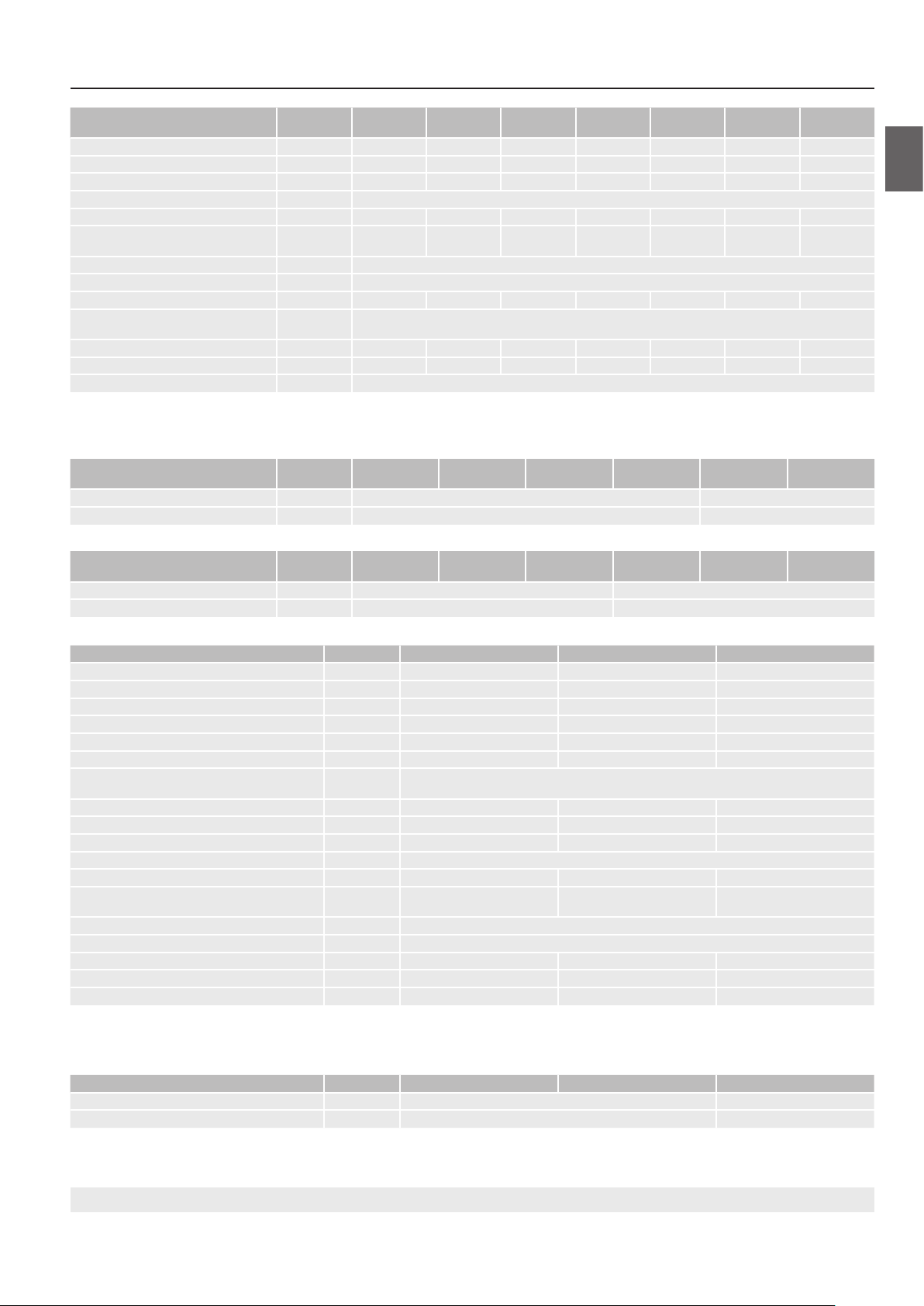
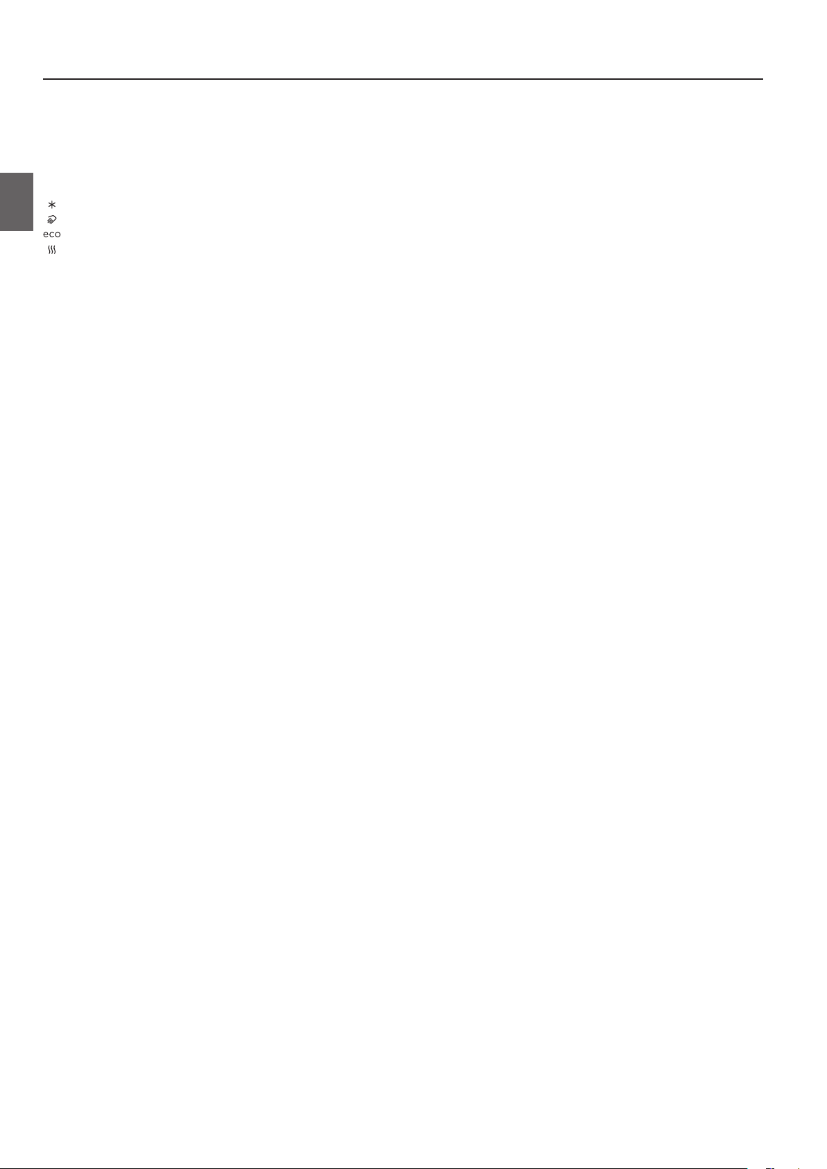
PRIKLJUČITEV NA DRUGE VIRE OGREVANJA
Hranilnik tople vode omogoča pripravo sanitarne vode preko izmenjevalca toplote z različnimi viri energije (npr. centralno
ogrevanje, sončna energija, ...).
Primera povezave hranilnika tople vode z različnimi viri ogrevanja sta prikazana na skicah.
LEGENDA
1 Hranilnik tople vode
2 Kotel centralnega ogrevanja
3 Sprejemnik sončne energije
4 Diferenčni termostat s tipali
(T1, T2, T3, T4)
5 Obtočna črpalka
6 Ekspanzijska posoda
7 Protipovratni ventil
1
6
T
1
9
T
2
3
4
8 Varnostni ventil
9 Ventil za odzračevanje
10 Ventil za polnjenje in praznjenje sistema
11 Reducirni ventil
12 Izpustni ventil
13 Zaporni ventil
14 Preizkusni nastavek
15 Lijak s priključkom na odtok
8
7
5
2
T
4
9
7
3
12
5
1
T
1
12 8 7
15
14 11 13
10
141113
12
87
15
Sl. 7: Povezava s sprejemniki sončne energije Sl. 8: Povezava s kotlom centralnega ogrevanja
7
518375

UPORABA IN VZDRŽEVANJE
Po priključitvi na vodovodno in električno omrežje ter druge vire ogrevanja je hranilnik tople vode pripravljen za uporabo. Običajno
je osnovni vir za ogrevanje sanitarne vode centralno ogrevanje ali sončna energija, pri čemer je regulacija ogrevanja tople vode
izvedena v sistemu ogrevanja.
SL
Vgradni električni grelec je namenjen le za dodatno ogrevanje vode. Temperaturo nastavljate z vrtenjem gumba v smeri urinega
kazalca na želen temperaturni nivo.
- Zaščita proti zmrzovanju, temperatura približno 10 °C.
- Temperatura vode približno 35 °C.
- Temperatura vode približno 55 °C.
- Temperatura vode približno 85 °C.
Termometer prikazuje temperaturo na mestu vgradnje, medtem ko z vrtenjem gumba na termostatu nastavljate temperaturo vode
v spodnjem delu hranilnika. Zato se ti dve temperaturi lahko razlikujeta.
Kadar obstaja nevarnost, da bo voda v hranilniku zmrznila, jo morate iz njega iztočiti. Voda iz hranilnika se izprazni skozi dotočno
cev hranilnika. V ta namen je priporočljivo ob vgradnji med varnostni ventil in dotočno cev namestiti poseben T-člen z izpustnim
ventilom. Pred praznjenjem je hranilnik potrebno izključiti iz električnega omrežja, zapreti dovod hladne vode v hranilnik, odpreti
ročico za toplo vodo na priključeni mešalni bateriji in počakati da se voda v hranilniku ohladi. Po izpraznitvi vode skozi dotočno cev,
v hranilniku ostane manjša količina vode.
Zunanjost hranilnika čistite z mehko krpo in blagimi tekočimi čistili. Ne uporabljajte čistil, ki vsebujejo alkohol ali abrazivna sredstva.
Z rednimi servisnimi pregledi boste zagotovili brezhibno delovanje in dolgo življenjsko dobo hranilnika. Garancija za prerjavenje
kotla velja le, če ste izvajali predpisane redne preglede izrabljenosti zaščitne anode. Obdobje med posameznimi rednimi pregledi ne
sme biti daljše kot je navedeno v garancijski izjavi. Pregledi morajo biti izvedeni s strani pooblaščenega serviserja, ki Vam pregled
evidentira na garancijskem listu proizvoda. Ob pregledu preveri izrabljenost protikorozijske zaščitne anode in po potrebi očisti
vodni kamen, ki se glede na kakovost, količino in temperaturo porabljene vode nabere v notranjosti hranilnika. Servisna služba vam
bo po pregledu hranilnika glede na ugotovljeno stanje priporočila tudi datum naslednje kontrole.
Prosimo Vas, da morebitnih okvar na hranilniku ne popravljate sami, ampak o njih obvestite najbližjo pooblaščeno
servisno službo.
518375
8
TEHNIČNE LASTNOSTI APARATA
Tip *
Razred energijske učinkovitosti
Lastna izguba S
2)
VLG 200
A1-1G
1)
C B C C B B B
[W] 70,8 58,3 88,8 88,8 68 68 71,9
VLG 200
A3-1G
VLG 300
B1-1G
VLG 300
B2-1G
VLG 300
C1-1G
VLG 300
C1-2G
VLG 400
C1-1G
Prostornina za shranjevanje [l] 184 190,3 275,5 262 283,7 283,7 396
Nazivni tlak [MPa (bar)] 0,6 (6); 0,9 (9); 1,0 (10)
Masa / napolnjen z vodo [kg] 97 / 281 115 / 305 140 / 416 165 / 427 165/449 170/454 230/626
Protikorozijska zaščita kotla
Emajlirano / Mg anoda
• / • • / • • / • • / • • / • • / • • / •
Razred zaščite I
Stopnja zaščite IP24
Površina prenosnika toplote [m2] 2,0 2,3 2,5 4,0 3,45 1,05 + 2,4 6,15
Temperatura grelnega medija v
prenosniku toplote
[°C] < 95
Debelina izolacije [mm] 60 110 67 67 75 75 75
Toplotne izgube
2)
[kWh/24h] 1,7 1,4 2,1 2,1 1,6 1,6 1,7
Maksimalni premer tipal [mm] ø8
* Če v tipski oznaki ni črke G, je aparat brez električnega grelca.
1)
Uredba komisije EU 812/2013
2)
Testirano po EN 12897:2006
Model
VLG 200
A1-1G3
VLG 200
A3-1G3
VLG 300
B1-1G3
VLG 300
B2-1G3
VLG 300
B1-1G6
VLG 300
B2-1G6
Priključna moč [W] 3000 6000
Napetost [V~] 230 400
Model
VLG 300
C1-1G3
VLG 300
C1-2G3
VLG 400
C1-1G3
VLG 300
C1-1G6
VLG 300
C1-2G6
VLG 400
C1-1G6
Priključna moč [W] 3000 6000
Napetost [V~] 230 400
SL
Tip
Profil rabe
Razred energijske učinkovitosti
1)
Energijska učinkovitost ogrevanja vode ƞwh
Letna poraba električne energije
Dnevna poraba električne energije
1)
2)
Nastavitev temperature termostata
Morebitni varnostni ukrepi
(sestava, nameščanje, vzdrževanje)
Vrednost smart
Prostornina za shranjevanje V
Mešana voda pri 40°C V40
2)
Nazivni tlak
Masa / napolnjen z vodo
Protikorozijska zaščita kotla
Emajlirano / Mg anoda
Razred zaščite
Stopnja zaščite
Debelina izolacije
Toplotne izgube
3)
Čas segrevanja od 10 do 65 °C
1)
Uredba komisije EU 812/2013; EN 50440
2)
EN 50440
3)
Testirano po SIST EN 60379:2005
Model
Priključna moč
Napetost
VLG 200 A-G VLG 300 B-G VLG 400 C-G
XL XL XL
C C C
1)
[%] 38,1 38,0 38,1
[kWh] 4399 4412 4400
[kWh] 20,317 20,397 20,328
"eco" "eco" "eco"
Pri tlačni priključitvi obvezna uporaba varnostnega ventila
0 0 0
[l] 203 319 449
[l] 305 508 712
[MPa (bar)] 0,6 (6); 0,9 (9); 1,0 (10)
[kg] 63/265 97/397 230/626
• / • • / • • / •
I
IP24
[mm] 60 67 75
[kWh/24h] 1,7 2,1 1,7
[h] 4
25
56
6
VLG 200 A-G3 VLG 300 B-G3 VLG 400 C-G6
[W] 3000 6000
[V~] 230 400
53
4
PRIDRŽUJEMO SI PRAVICO DO SPREMEMB, KI NE VPLIVAJO NA FUNKCIONALNOST APARATA.
Navodila za uporabo so na voljo tudi na naših spletnih straneh http://www.gorenje.com.
9
518375

WARNINGS
The appliance may be used by children aged 8 and older and persons with physical, sensory or mental
disabilities or lacking experience or knowledge, if they are under supervision or taught about safe use of the
appliance and if they are aware of the potential dangers.
Children should not play with the appliance.
Children should not clean or maintain the appliance without supervision
EN
The installation should be performed in accordance with the valid regulations and the instructions of the
manufacturer. It should be performed by a professionally trained installation expert.
It is obligatory to install a safety valve with a rated pressure of 0.6 MPa (6 bar), 0.9 MPa (9 bar) or 1.0 MPa (10
bar) – see the label - on the inlet pipe of the hot water storage tank to prevent the elevation of pressure in the
tank by more than 0.1 MPa (1 bar) above the rated pressure.
Water may drip from the outlet opening of the safety valve, so the outlet opening should be set to atmospheric
pressure.
The outlet of the safety valve should be installed facing downwards and in a non-freezing area.
To ensure proper functioning of the safety valve, the user should perform regular controls to remove limescale
and make sure the safety valve is not blocked.
Do not install a stop valve between the hot water storage tank and the safety valve, because it will impair the
pressure protection of the storage tank!
Before connecting the heater to the power supply, the storage tank must be filled with water!
The storage tank is protected in case of failure of the operating thermostat with an additional thermal cut-out.
In case of thermostat failure water in the storage tank may reach the temperature of up to 130°C in accordance
with safety standards. The possibility of such temperature overload should be taken into consideration in the
execution of plumbing.
Should you choose to disconnect the power, the storage tank should be drained thoroughly before the onset of
freezing conditions.
Water from the storage tank is drained through the inlet pipe of the tank. For this purpose, a special fitting
(T-fitting) with an outlet valve must be mounted between the safety valve and the inlet pipe.
Please do not try to fix any defects of the storage tank on your own. Call the nearest authorised service provider.
518375
Our products incorporate components that are both environmentally safe and harmless to health, so they can
be disassembled as easily as possible and recycled once they reach their final life stage.
Recycling of materials reduces the quantity of waste and the need for production of raw materials (e.g. metals)
which requires a substantial amount of energy and causes release of harmful substances. Recycling procedures
reduce the consumption of natural resources, as the waste parts made of plastic and metal can be returned to
various production processes.
For more information on waste disposal, please visit your waste collection centre or the store where the
product was purchased
10
øJ
I
Dear buyer, thank you for purchasing our product.
PRIOR TO THE INSTALLATION AND FIRST USE OF THE HOT WATER STORAGE
TANK, PLEASE READ THESE INSTRUCTIONS CAREFULLY.
This storage tank has been manufactured in compliance with the relevant Standards and tested by the relevant authorities as
indicated by the Safety Certificate and the Electromagnetic Compatibility Certificate. The technical characteristics of the product
are listed on the label attached to the protective cover.
The connection of the storage tank to the plumbing and power networks must be carried out by qualified staff only. All repairs
and maintenance work in the interior of the storage tank, as well as limestone removal or testing or replacement of the corrosion
protection anode, may only be carried out by an approved maintenance service provider.
The hot water storage tank is designed in a manner which allows using the following heating sources, via a heat exchanger:
• Central heating hot-water system,
• Solar power,
• Heating pump.
INSTALLATION
The heater should be installed in a dry room that is not subject to freezing conditions, preferably in the vicinity of other sources
of heating (e.g. boiler room). Prior to installation screw on the enclosed adjustable legs. Level the storage tank longitudinally and
transversally by rotating the adjustable legs.
5
4
H
3
A
EN
KEY
G
2
1
C D
B
VLG 200 A1-1G VLG 200 A3-1G VLG 300 B1-1G VLG 300 B2-1G VLG 300 C1-1G VLG 400 C1-1G
A 1535 1675 1590 1590 1445 1915
B 180 220 175 175 250 250
C 300 340 270 270 370 370
D 880 1015 890 890 610 1070
G 780 945 740 740 800 990
H 1355 1435 1410 1410 1205 1675
I 365 405 320 340 400 400
J 580 680 680 680 760 760
1 G 3/4 G 3/4 G1 G1 G1 G1
2 G1 G1 G1 G 5/4 G 5/4 G 5/4
3 G 3/4 G 3/4 G 3/4 G 3/4 G 3/4 G 3/4
4 G1 G1 G1 G 5/4 G 5/4 G 5/4
5 G 3/4 G 3/4 G1 G1 G1 G1
Image 1: Connection and installation dimensions of the storage tank [mm]
1 Cold water inflow
2 Medium outlet from the heat exchanger
3 Circulation conduit
4 Medium inflow into the heat exchanger
5 Hot water outflow
11
518375

øJ
I
I
5
4
3
2
4
225 425
2
1
C D
B
EN
H
G
VLG 300 C1-2G
A 1445
B 250
C 370
D 740
G 800
H 1205
I 400
J 760
1 G1
2 G5/4
3 G 3/4
4 G5/4
5 G1
Image 2: Connection and installation dimensions of the storage tank [mm]
A
KEY
1 Cold water inflow
2 Medium outlet from the heat exchanger
3 Circulation conduit
4 Medium inflow into the heat exchanger
5 Hot water outflow
518375
øJ
VLG 200
A-G
5
A [mm] 1535 1590 1915
VLG 300
B-G
VLG 400
B-G
B [mm] 180 175 250
G [mm] 780 740 990
H [mm] 1355 1410 1675
I [mm] 365 320 400
J [mm] 580 680 760
H
3
A
1 G 3/4 G1 G1
3 G 3 /4 G 3/4 G 3/4
5 G 3 /4 G1 G1
G
1
B
KEY
1 Cold water inflow
3 Circulation conduit
5 Hot water outflow
12

CONNECTION TO THE WATER SUPPLY
765ba43218
Connection to water supply should be made according to the markings for the connections, as defined in the previous Chapter.
For safety reasons the supply pipe must be fitted with a safety valve or, alternatively, a valve of the safety class that prevents the
pressure in the tank from exceeding the nominal pressure by more than 0.1 MPa (1 bar). The outlet opening on the safety valve
must be equipped with an outlet for atmospheric pressure. The heating of water in the storage tank causes the pressure in the tank
to increase to the level set by the safety valve. As the water cannot return to the water supply system, this can result in dripping
from the outlet opening of the safety valve. The drip can be piped to a drain by installing a catching unit just below the safety
valve. The drain installed below the safety valve outlet must be piped down vertically and placed in an environment that is free
from the onset of freezing conditions.
In case you want to avoid water dripping from the safety valve, an expansion tank for domestic water with at least 5 % of the
volume of the storage tank should be installed on the inlet pipe of the storage tank.
To ensure proper functioning of the safety valve, the user should perform regular controls to remove limescale and make sure the
safety valve is not blocked. To check the valve, open the outlet of the safety valve by turning the handle or unscrewing the nut of the
valve (depending on the type of valve). The valve is operating properly if the water comes out of the nozzle when the outlet is open.
KEY
1 Drain valve
2 Expansion tank
3 Safety valve
a - Test valve
b - Non-return valve
4 Funnel outlet to the drain
5 Test unit
6 Pressure-reducing valve
T
H
7 Stop valve
8 Pressure mixer taps
EN
H Cold water
T Hot water
Image 3: Closed (pressure) system
The storage tank can be connected to the domestic water supply network without a pressure regulator if the pressure in the
network is lower than the nominal pressure (see the label). If the pressure in the network exceeds the nominal pressure, a pressure
regulator must be installed.
13
518375

CONNECTION TO THE POWER SUPPLY NETWORK
L
230 V~
3F Y 230 V~
N
2
L3
N
L1
L2
Before connecting the storage tank to the power supply network, a connection cable with a minimum cross-section of at least
1.5 mm2 (H05VV-F 3G 1.5 mm2) for a 3kW-heating element and 2.5 mm2 for a 6kW-heating element (H05VV-F 5G 2,5 mm2) must be
installed in it and the protection cover must be removed.
This is done by pulling out the knob on the thermostat axis and unscrewing two screws.
An all-pole disconnect device must be installed in the electric installation to comply with the National Installation Regulations.
EN
Image 4: Removal of heater cover
STB
ΔT
1
1
+°C
A
B
2
STB
ΔT
+°C
A1
A2
A3 B3
Image 5: Schemes of electric installations
TR
+°C
TR
+°C
R1 R2
3
R3
1
2
KEY
1 Connection terminal
R1 R2
2 A thermostat and a bipolar or tripolar thermal
cut-out
B1
B2
R3 R4 R5 R6
3
3 Heater
L Live conductor
L1 Live conductor
L2 Live conductor
L3 Live conductor
N Neutral conductor
Earthing conductor
518375
14
INSTALLATION OF SENSORS
On the upper side of the storage tank there are two sensor tubes for mounting the sensors for regulation of the system connection
of the hot water storage tank to other heating sources. The maximum diameter of the sensors is 8 mm.
Long sensor tube (lower tank position)
Short sensor tube (upper tank position)
Image 6: Installation of sensors
WARNING: Before any intervention into the interior of the storage tank disconnect it from the power supply! All
interventions must be carried out by qualified staff only!
EN
CONNECTION TO ALTERNATIVE
SOURCES OF HEATING
The hot water storage tank enables the water for sanitary use to be heated by alternative sources of energy (e.g. central heating,
solar power etc.) by installing a Heat Exchanger.
Examples of connecting the hot water storage tank to various sources of heating are shown in the drawings below.
KEY
1 Hot water storage tank
2 Central heating hot-water system
3 Solar panel
4 Differential thermostat with sensors
(T1, T2, T3, T4)
5 Bypass pump
6 Expansion tank
7 Non-return valve
9
T
2
3
1
4
8 Safety valve
9 Air relief valve
10 Fill/drain valve
11 Reduction valve
12 Drain valve
13 Stop valve
14 Test unit
15 Funnel outlet to the drain
4
1
8
6
T
1
12 8 7
Image 7: Connection to solar panels Image 8: Connection to the central heating hot-water system
14 11 13
15
7
5
10
2
T
3
12
9
7
5
141113
12
87
15
T
1
15
518375
USE AND MAINTENANCE
The hot water storage tank is ready for use once it has been connected to water and electricity and other heating sources. The
usual main sources for heating domestic water are central heating or solar power; in this case any regulation of water heating is
performed in the heating system.
The built-in electric heating element is designed for backup heating of water only. The temperature is set by turning the knob in a
clockwise direction to reach the desired temperature level.
- Protection against freezing, temperature around 10 °C.
EN
- Water temperature around 35 °C.
- Water temperature around 55 °C.
- Water temperature around 85 °C.
The thermometer shows the in-situ temperature, whereas by turning the knob on the thermostat the water temperature in the
lower part of the storage tank is set. Thus, these two temperatures may vary.
In case of exposure to sub-zero temperatures, the water should be drained from the storage tank thoroughly before the onset of
freezing conditions. Water from the storage tank is drained through the inlet pipe of the storage tank. For this purpose, a special
fitting (T-fitting) with an outlet valve must be mounted between the safety valve and the inlet pipe. Before discharge make sure the
storage tank is disconnected from the power supply, close the inlet of cold water into the storage tank, open the hot water tap on
the connected mixer tap and wait for the water in the storage tank to cool down. After discharging through the inlet pipe there is
still some water left in the storage tank.
The external parts of the water heater may be cleaned with a soft cloth and mild cleaning fluids. Do not use cleaning fluids
containing alcohol or abrasives.
Regular preventive maintenance inspections ensure faultless performance and long life of your storage tank. Tank Warranty is
subject to regular inspections of the wear of the protective anode. The period between individual regular inspections should not be
longer than specified in the Guarantee statement. Inspection should be carried out by an authorised maintenance service provider
recording the inspection on the Guarantee Certificate of the product. During the inspection, the wear of the corrosion protection
anode will be inspected and any limestone built up in the interior of the storage tank, depending on the quality, quantity and
temperature of used water, will be removed as required. After inspecting the storage tank, the maintenance service provider will
also recommend the date of the next inspection according to the ascertained status.
Please do not try to fix any defects of the storage tank on your own. Call the nearest authorised service provider.
518375
16

TECHNICAL CHARACTERISTICS OF THE APPLIANCE
Type *
Energy efficiency class
Standing loss S
2)
VLG 200
A1-1G
1)
C B C C B B B
[W] 70,8 58,3 88,8 88,8 68 68 71,9
VLG 200
A3-1G
VLG 300
B1-1G
VLG 300
B2-1G
VLG 300
C1-1G
VLG 300
C1-2G
VLG 400
C1-1G
Storage volume [l] 184 190,3 275,5 262 283,7 283,7 396
Rated pressure [MPa (bar)] 0,6 (6); 0,9 (9); 1,0 (10)
Weight/filled with water [kg] 97 / 281 115 / 305 140 / 416 165 / 427 165/449 170/454 230/626
Anti-corrosion protection of tank
Enamelled/Mg anode
• / • • / • • / • • / • • / • • / • • / •
Protection class I
Degree of protection IP24
Heat exchanger surface [m2] 2,0 2,3 2,5 4,0 3,45 1,05 + 2,4 6,15
Temperature of the heating medium
in the heat exchanger
[°C] < 95
Insulation thickness [mm] 60 110 67 67 75 75 75
Heat loss
2)
[kWh/24h] 1,7 1,4 2,1 2,1 1,6 1,6 1,7
Maximum diameter of sensors [mm] ø8
* If there is no letter G in the type designation, the appliance does not include the electric heater.
1)
Commission Regulation EU 812/2013
2)
Tested pursuant to EN 12897:2006
Model
VLG 200
A1-1G3
VLG 200
A3-1G3
VLG 300
B1-1G3
VLG 300
B2-1G3
VLG 300
B1-1G6
VLG 300
B2-1G6
Connected load [W] 3000 6000
Voltage [V~] 230 400
Model
VLG 300
C1-1G3
VLG 300
C1-2G3
VLG 400
C1-1G3
VLG 300
C1-1G6
VLG 300
C1-2G6
VLG 400
C1-1G6
Connected load [W] 3000 6000
Voltage [V~] 230 400
EN
Type
Use profile
Energy eciency class
1)
Energy eciency of water heating ƞwh
Annual electrical energy consumption
Daily electrical energy consumption
2)
Set thermostat temperature
Potential safety measures
(assembly, installation, maintenance)
Smart value
Storage volume
Mixed water at 40 °C V40 2)
Rated pressure
Weight/filled with water
Anti-corrosion protection of tank
Enamelled/Mg anode
Protection class
Degree of protection
Insulation thickness
Heat loss
3)
Heating time from 10 °C to 65 °C
1)
directive 812/2013; EN 50440
2)
EN 50440
3)
Tested pursuant to SIST EN 60379:2005
Model
Connected load
Voltage
VLG 200 A-G VLG 300 B-G VLG 400 C-G
XL XL XL
C C C
1)
1)
[%] 38,1 38,0 38,1
[kWh] 4399 4412 4400
[kWh] 20,317 20,397 20,328
"eco" "eco" "eco"
Compulsory use of a safety valve with the pressure connection.
0 0 0
[l] 203 319 449
[l] 305 508 712
[MPa (bar)] 0,6 (6); 0,9 (9); 1,0 (10)
[kg] 63/265 97/397 230/626
• / • • / • • / •
I
IP24
[mm] 60 67 75
[kWh/24h] 1,7 2,1 1,7
[h] 4
25
56
6
53
4
VLG 200 A-G3 VLG 300 B-G3 VLG 400 C-G6
[W] 3000 6000
[V~] 230 400
WE RESERVE THE RIGHT TO ANY MODIFICATIONS NOT AFFECTING THE FUNCTIONALITY OF THE APPLIANCE.
The instructions for use are also available on our website http://www.gorenje.com.
17
518375

518375
18

19
518375

VLG 200 - 400 05/2017
518375
 Loading...