

Gorenje Aerogor ECO COMPACT INVERTER 13A, Aerogor ECO COMPACT INVERTER 10A, Aerogor ECO Inverter 13 A, Aerogor ECO Inverter 10 A, Aerogor POWER EVI Inverter 18 A Installation Manual
...Page 1
www.gorenje.com
V 2.0
Aerogor ECO Inverter 10A/13A
Aerogor ECO COMPACT Inverter 10A/13A
Aerogor POWER EVI Inverter 15A/18A
INSTALLATION MANUAL
Page 2

Page 3

TABLE OF CONTENTS
1 BEFORE USE ................................................................................................................ 1
1.1 WARNINGS ............................................................................................................ 1
1.2 DISPOSAL .............................................................................................................. 3
1.3 HEATING SYSTEM REQUIREMENTS (MANDATORY) ......................................... 3
1.4 INCLUDED IN THE PACKAGE ............................................................................... 4
1.5 TECHNICAL TABLE ................................................................................................ 5
1.5.1 AEROGOR ECO COMPACT INVERTER 10A, 13A ......................................... 5
1.5.2 AEROGOR ECO INVERTER 10A, 13A ............................................................ 6
1.5.3 AEROGOR POWER EVI INVERTER 15A, 18A ............................................... 7
1.6 DIMENSIONS ......................................................................................................... 8
1.6.1 INDOOR UNITS ............................................................................................... 8
1.6.2 OUTDOOR UNITS ........................................................................................... 9
1.7 OPERATING RANGE ............................................................................................10
1.8 WORKING PRINCIPLE ..........................................................................................11
1.9 MAIN COMPONENTS ............................................................................................12
1.9.1 INDOOR UNITS ..............................................................................................12
1.9.2 OUTDOOR UNITS ..........................................................................................14
1.9.3 AEROGOR POWER EVI INVERTER 15A/ 18A ..............................................16
2 INSTALLATION .............................................................................................................17
2.1 INSTALLATION OF THE INDOOR UNIT ...............................................................17
2.2 INSTALLATION OF THE OUTDOOR UNIT............................................................18
2.3 FOUNDATION .......................................................................................................20
2.3.1 INSTALLATION OF C PROFILE AND LEGS ..................................................21
2.4 INSTALATION OF THE REFRIGERANT SYSTEM (SPLIT TYPE) .........................22
2.4.1 Height difference between indoor and outdoor unit .........................................24
2.5 INSTALATION OF HYDRAULIC CONNECTIONS (COMPACT TYPE) ..................26
3 ELECTRICAL WIRING ..................................................................................................27
3.1 AEROGOR ECO INVERTER 10A, 13A AND AEROGOR POWER EVI INVERTER
15A, 18A ...........................................................................................................................27
3.1.1 INDOOR UNIT ................................................................................................27
3.1.2 TEMPERATURE SENSORS ...........................................................................28
3.1.3 CONNECTION BETWEEN INDOOR AND OUTDOOR UNIT ..........................29
3.2 AEROGOR ECO COMPACT INVERTER 10A, 13A ...............................................30
3.2.1 INDOOR UNIT ................................................................................................30
Page 4

3.2.2 TEMPERATURE SENSORS ...........................................................................31
3.2.3 CONNECTION BETWEEN INDOOR AND OUTDOOR UNIT ..........................32
4 CONTROL UNIT ...........................................................................................................33
4.1 DESCRIPTION OF SYMBOLS ON THE CONTROL UNIT .....................................33
4.2 DESCRIPTION OF THE TEMPERATURES ON THE CONTROL UNIT .................36
5 QUICK SETTINGS ........................................................................................................37
5.1 PARALLEL MOVE OF THE HEATING CURVE ......................................................37
5.1.1 SETTING THE PARALLEL MOVE OF THE HEATING CURVE – HEATING
CIRCUIT 1 .....................................................................................................................37
5.1.2 SETTING THE PARALLEL MOVE OF THE HEATING CURVE – HEATING
CURVE 2.......................................................................................................................38
5.1.3 SETTING THE DHW TEMPERATURE ...........................................................38
5.2 SETTING THE FIXED TEMPERATURE OF HEATING CIRCUIT ...........................39
5.2.1 SETTING THE FIXED TEMPERATURE FOR THE FIRST HEATING CIRCUIT
39
5.2.2 SETTING THE FIXED TEMPERATURE FOR THE SECOND HEATING
CIRCUIT .......................................................................................................................39
6 USER INTERFACE .......................................................................................................40
6.1 ARRANGMENT OF MENUS ..................................................................................40
6.2 MENU ACCESS .....................................................................................................40
6.3 SETTINGS .............................................................................................................41
6.3.1 Heating/Cooling Circuit 1 .................................................................................41
6.3.2 Heating/Cooling circuit 2 .................................................................................45
6.4 DHW SETTINGS ....................................................................................................47
6.5 DHW STORAGE ....................................................................................................49
6.5.1 Sanitary Hot Water Storage Function ..............................................................50
6.5.2 Sanitary Hot Water Storage Timer ...................................................................50
6.5.3 Reheating Function .........................................................................................50
6.5.4 Reheating Function Timer ...............................................................................50
6.5.5 Reheating Set Temp. ......................................................................................50
6.5.6 Reheating Restart ∆T Setting ..........................................................................51
6.6 REDUCED SETPOINT ...........................................................................................51
6.6.1 Reduced Setpoint ............................................................................................51
6.6.2 Temp. Drop/Rise .............................................................................................51
6.6.3 Timer for Reduced Setpoint Function ..............................................................51
6.6.4 Quiet Operation ...............................................................................................52
6.6.5 Allowable Temp. Drifting .................................................................................52
6.6.6 Timer for Quiet Operation ................................................................................52
Page 5

6.7 ANTI – LEGIONELLA .............................................................................................52
6.7.1 Anti – Legionella Program ...............................................................................52
6.7.2 Day and Time ..................................................................................................53
6.7.3 Setpoint ...........................................................................................................53
6.7.4 Duration ..........................................................................................................53
6.7.5 Finish Time .....................................................................................................53
6.8 VACATION MODE .................................................................................................53
6.8.1 Vacation Mode ................................................................................................53
6.8.2 Sanitary Hot Water Temp. Drop during Vacation Mode ...................................54
6.8.3 Heating Water Temp. Drop during Vacation Mode ..........................................54
6.8.4 Vacation Start Date .........................................................................................54
6.8.5 Vacation Finish Date .......................................................................................54
6.9 USER MANAGEMENT ...........................................................................................54
6.9.1 Permission Level .............................................................................................54
6.9.2 Heating/Cooling ON/OFF timer .......................................................................54
6.9.3 Language ........................................................................................................55
6.9.4 Set Date and Time ................................................................ ..........................55
6.9.5 Distribution System Setting .............................................................................55
6.9.6 Save Current Settings .....................................................................................55
6.9.7 Load Saved Settings .......................................................................................55
6.9.8 Switch to Factory Settings ...............................................................................55
6.10 MODE SETTINGS..................................................................................................56
6.10.1 Sanitary Hot Water ..........................................................................................56
6.10.2 Heating............................................................................................................56
6.10.3 Cooling ................................................................ ............................................56
6.10.4 Basic Operation Modes ...................................................................................56
6.10.5 Cooling and Heating Switch ............................................................................57
6.10.6 Ambient Temp. To Start Heating .....................................................................57
6.10.7 Ambient Temp. To Start Cooling .....................................................................58
6.11 BACKUP HEATING ................................................................................................58
6.11.1 Backup Heating Sources for Heating ...............................................................59
6.11.2 Priority for Backup Heating Sources (HBH) .....................................................59
6.11.3 Backup Heating Source for Sanitary Hot Water ...............................................60
6.11.4 Priority for Backup Heating Sources (HWTBH) ................................................60
6.11.5 Heating Source Start Accumulating Value (HBH) ............................................60
6.11.6 Water Temperature Rise Reading Interval (hwtbh) ..........................................60
6.11.7 Emergency Operation .....................................................................................60
Page 6

6.12 WATER PUMP SETTINGS ...................................................................................61
6.12.1 Circulation Pump P0 Type ...............................................................................61
6.12.2 Speed Setting of Circulation Pump P0 ............................................................62
6.12.3 Working Mode of Circulation Pump P0 ............................................................62
6.12.4 Pump Off Interval for P0 ..................................................................................62
6.12.5 Pump On Time for P0 ......................................................................................62
6.12.6 Buffer Tank .....................................................................................................62
6.12.7 P1 For Heating Operation ...............................................................................62
6.12.8 P1 For Cooling Operation ................................................................................62
6.12.9 P1 with High Temp. Demand ...........................................................................62
6.12.10 P2 for Heating Operation .............................................................................62
6.12.11 P2 for Cooling Operation .............................................................................63
6.12.12 P2 with High Temp. Demand .......................................................................63
6.13 FLOOR CURING ....................................................................................................63
6.13.1 Floor Curing ....................................................................................................64
6.13.2 Floor Curing Current Stage .............................................................................64
6.13.3 Floor Curing Current Stage Running Duration .................................................64
6.13.4 Floor Curing Current Stage Set Temperature ..................................................64
6.13.5 Floor Curing Current Stage Valid Running Duration ........................................64
6.13.6 Floor Current Total Running Duration ..............................................................64
6.13.7 Highest Water Temp. in Floor Curing Operation ..............................................64
6.14 ELECTRICAL UTILITY LOCK ................................................................................65
6.14.1 Electrical Utility Lock .......................................................................................65
6.14.2 Operation Signal for Electrical Utility Lock .......................................................66
6.14.3 HBH During Electrical Utility Lock....................................................................66
6.14.4 P0 during Electrical Utility Lock .......................................................................66
6.14.5 Heating Eco Operation ....................................................................................66
6.14.6 Ambient Temp. to Start Heating Eco Operation ...............................................66
6.15 OTHER OPTIONS..................................................................................................67
6.15.1 Motorized Diverting Valve switching time ........................................................67
6.15.2 Power on Time for Motorized Diverting Valve ..................................................67
6.15.3 Refrigerant Recycle Function ..........................................................................67
6.15.4 Control Panel Backlight Light ..........................................................................67
6.15.5 Exit System .....................................................................................................68
6.15.6 Anti-freezing protection ...................................................................................68
6.15.7 Mode Switch during Defrosting ........................................................................68
6.15.8 Mode Signal Output.........................................................................................68
Page 7

6.15.9 Mode Signal type ............................................................................................68
6.15.10 Fan Speed Limit ..........................................................................................68
6.15.11 Defrosting Logic Selection ...........................................................................69
6.15.12 Activate Wi-Fi module or not? ......................................................................69
6.15.13 Accept setting from Wi-Fi module? ..............................................................69
6.15.14 Connection to the server ..............................................................................69
6.15.15 Connection to the router ..............................................................................69
6.15.16 MAC ............................................................................................................69
6.15.17 WI-FI module IP address .............................................................................69
6.15.18 SSID ............................................................................................................69
6.15.19 Password .....................................................................................................69
6.15.20 Server address ............................................................................................69
6.15.21 Service port .................................................................................................69
6.16 UNIT REAL-TIME DATA ................................ ........................................................70
7 ERROR CODES............................................................................................................70
7.1 ERROR CODES SHOWN ON THE DISPLAY ........................................................70
7.2 ERROR CODE MENU ...........................................................................................70
7.2.1 ACCESSING THE ERROR CODE MENU .......................................................70
7.2.2 INFORMATIONS IN THE ERROR CODE MENU ............................................71
7.2.3 INFO PAGE ....................................................................................................71
7.3 ERROR CODE LIST ..............................................................................................73
8 CLEANING THE MAGNETIC/DIRT FILTER CALEFFI ..................................................79
9 WATER PRESSURE IN THE SYSTEM .........................................................................80
10 WIRING .....................................................................................................................81
10.1 INDOOR UNIT - ALL INVERTERS .........................................................................81
10.2 INDOOR UNIT TERMINALS – ECO10A,13A, POWER EVI 15A, 18A ....................83
10.3 OUTDOOR PCB ECO INVERTER .........................................................................84
10.4 DRIVE FOR EEV ...................................................................................................86
10.5 OUTDOOR UNIT – POWER EVI INVERTER 15A, 18A .........................................87
10.6 OUTDOOR UNIT DRIVE – AEROGOR POWER EVI 15A, 18A .............................89
Page 8
1
1 BEFORE USE
Thank you for purchasing our product. We ask that you carefully read the manual and to take
into account all of the instructions regarding device operation in order to prevent possible
damage to the device or personnel. Technical data can be changed without notice because
of product upgrades. Please look at the rating label on the device for latest technical
specifications.
1.1 WARNINGS
Warnings in this manual address most important topics for proper and safe operation of the
heat pump, for this reason follow them directly. For further questions contact your installer or
technical support from Gorenje d.d. Contact details are on the last page of this document.
Before first use, read this manual.
This unit can be used by children aged from 8 years and above and persons with
reduced physical, sensory or mental capabilities or lack of experience and knowledge
if they have been given supervision or instruction concerning use of the unit in a safe
way and understand the hazards involved. Children should not play with the unit.
Cleaning and user maintenance shall not be made by children without supervision.
Installation, dismantlement and maintenance must be carried out by qualified
personnel. Any change to structure of the unit is prohibited since they can lead to
personal injury or damage to the unit.
Water or any other kind of fluid should not come in contact with the unit, it may cause
electric shock or destruction of the unit.
If the power cord gets loose or damaged, it must be repaired by qualified personnel.
Page 9
2
To avoid electrical shock, make sure to disconnect the power supply 1 minute or more
before servicing the electrical parts. Even after 1 minute, measure the voltage at the
terminals of main circuit capacitors or electrical parts before touching. Make sure
those voltages are lower than the safe value.
Do not touch the grill of the ventilator while the device is operating.
Improper installation or attachment of equipment or accessories could result in
electric shock, short-circuit, leaks, fire or other damage to the equipment. Be sure
only to use accessories made by Gorenje which are specifically designed for use with
the equipment and have them installed by a professional.
Power supply to the device must be grounded.
For sanitary hot water, please always add a mixture valve before water tap and set it
to proper temperature.
Do not touch the fins of the coil with bare fingers, it might cause injury.
It is mandatory to use a suitable fuse for the heat pump and make sure the power
supply to the unit corresponds to the specifications. Otherwise the unit might be
damaged.
Please discard the batteries as sorted municipal waste at the accessible collection
point.
Instalation of a residual current device (RCD) having a rated residual operating
current of 300 mA.
Page 10

3
1.2 DISPOSAL
This marking indicates that this product should not be disposed with
other household wastes throughout the EU. To prevent possible harm to
the environment or human health from uncontrolled waste disposal,
recycle it responsibly to promote sustainable reuse of material
resources. To return your used device, please use the return and
collection systems or contact the retailer where the product was
purchased. They can take this product for environmental safe recycling.
1.3 HEATING SYSTEM REQUIREMENTS (MANDATORY)
• Installed magnetic filter and dirt separator filter.
• If city water is used for filling of the heating system, the water quality must
comply with local regulations.
• Heating system pressure must be between 1 - 1.8 bar.
• Safety valve (3 bar) must be installed in the heating system.
• Expansion vessels must be installed according to heating system.
• Heat pump must be installed into closed loop heating system.
• Installation maintenance must be carried out by qualified personnel.
• If the heat pump is being installed into an existing hydraulic system, the
system must be cleaned according to standard procedures.
Page 11
4
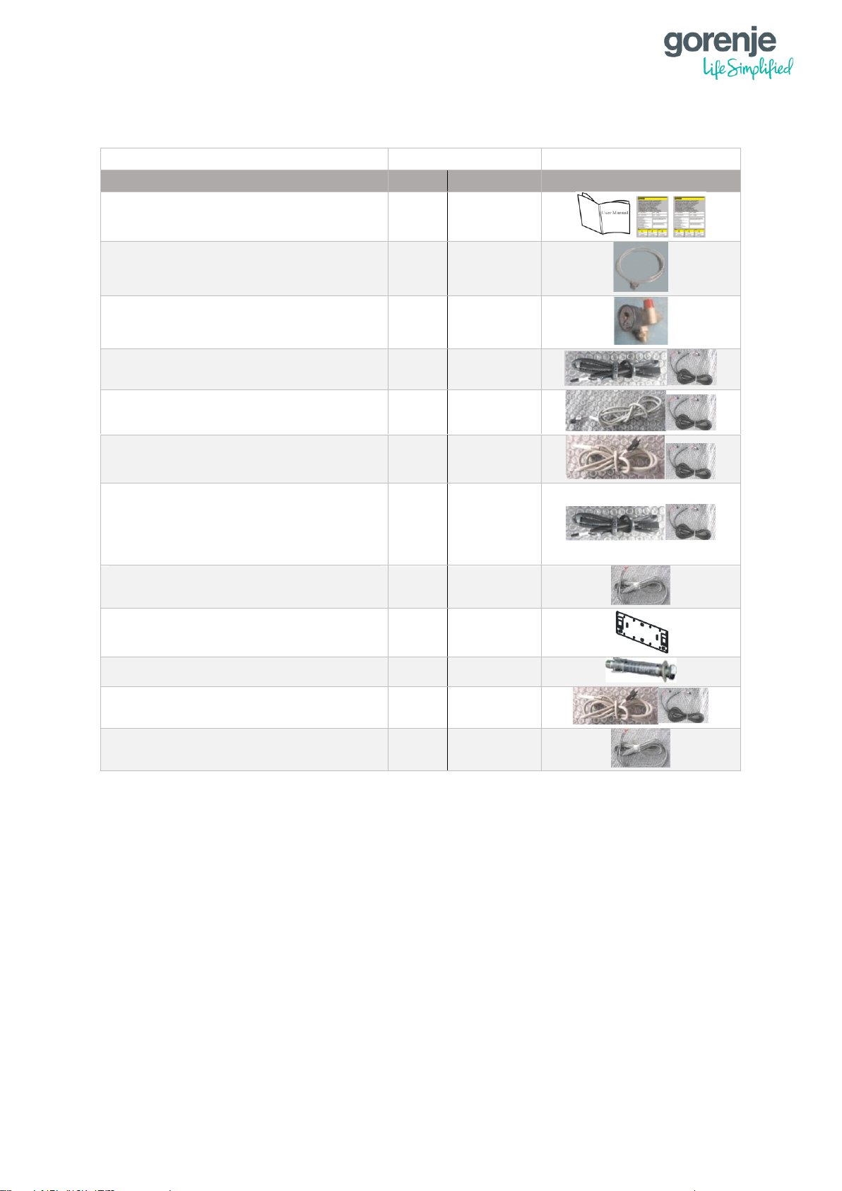
1.4 INCLUDED IN THE PACKAGE
NAME
QUANTITY
SYMBOLIC IMAGE
SPLIT
COMPACT
Installation Manual, Warranty cards
1
1
Drain pipe
1
1
Safety kit
1
1
TR – Room temp. sensor +
extension cable (10m)
1
1
TC – Heat/Cool temp. sensor +
extension cable (10m)
1
1
TW – DHW temp sensor + extension
cable (10m)
1
1
TV1 – mixing circuit 1 temp. sensor
+ extension cable (10m)
TV2 – mixing circuit 1 temp. sensor
+ extension cable (10m)
1
1
Communicaton cable
(20m)(shielded)
1
1
Bracket for indoor unit
1
1
Expansion bolts
2
1
Connection cable for Tui, Tuo, Tup
(20m)(shielded)
/
3 x 1
Connection cable for the Flow
Switch (20m) (shielded)
/
1
Page 12

5
1.5 TECHNICAL TABLE
1.5.1 AEROGOR ECO COMPACT INVERTER 10A, 13A
MODEL
ECO COMPACT INVERTER 10A
ECO COMPACT INVERTER 13A
ErP Energy efficiency class
A++
A++
SCOP 35°C (floor heating) EN 14825
3,83
4,08
P
design
for SCOP EN 14825
6,3 kW
7,46 kW
HEATING MODE (A7/W35)
Heating capacity*
4,57 – 10,50 kW
4,1 -12,2 kW
COP - Coefficient of Performance*
3,80 – 4,71
4,0 - 4,57
Max. temperature of heating water
55 °C
55 °C
Operating range of heat pump - Heating (Ambient temp.)
-25 do +45 °C
-25 do +45 °C
COOLING MODE (A35/W7)
Cooling capacity**
2,60 – 8,00 kW
2,34 – 7,91 kW
Rated input power**
1,10 – 3,50
0,97 – 2,98 kW
EER - Energy Efficiency Ratio**
2,30 – 3,22 kW
2,40 – 3,03
Min. temperature of cooling water
7 °C
7 °C
Operating range of heat pump - Cooling (Ambient temp.)
0 to +65 °C
0 to +65 °C
POWER SUPPLY - SPECIFICATION
Voltage
220-240 V/50 Hz/1 Ph
220-240 V/50 Hz/1 Ph
Rated input power*
0,91 – 3,05 kW
0,96 - 3,02 kW
Fuse for heat pump
1 X 1p/20A/C
1 x 1p/20A/C
Fuse for electrical flow heater
3 X 1p/10A/C
3 x 1p/10A/C
REFRIGERANT SPECIFICATION
Type of refrigerant
R410A
R410A
Refrigerant - mass
1,9 kg
3 kg
GWP (global warming potential)
2088 GWP
2088 GWP
Quantity of hydrofluorocarbons in tonnes of CO2 equivalent
4,051 t CO2 Equiv.
6,264 t CO2 Equiv.
Type of compressor
DC inverter (twin rotary)
DC inverter (twin rotary)
Hermetically sealed equipment (indoor/outdoor unit)
Yes
Yes
Type fo connection between outdoor-indoor unit
Refrigerant connection
Water connection
Dimensions of refrigerant pipes connectors
3/8” - 1/2”
/
FAN
Fan type
1 x Axial
2 x Axial
Air flow
3100 m3/h
4100 m3/h
Rated power
60 W
2 x 60 W
„ESP“ – External Static Pressure of the Fan (data per piece)
45 W
50 W
WATER SIDE HEAT EXCHANGER
Type
Plate heat exchanger
Plate heat exchanger
Pressure drop
30 kPa
40 kPa
Dimensions of water piping connection
G1"
G1"
ALLOWABLE FLOW - SECONDARY (WATER) SIDE
Min. water flow
1,15 m3/h
1,32 m3/h
Nominal water flow
1,44 m3/h
2,2 m3/h
Max. water flow
2,16 m3/h
2,63 m3/h
SOUND POWER AND PRESSURE LEVEL
Sound power level LwA - Indoor unit
45 dB(A)
46 dB(A)
Sound power level LwA - Outdoor unit
58 dB(A)
59 dB(A)
SOUND PRESSURE LEVEL ON DISTANCE
Indoor unit - 1 m
37 dB(A)
38 dB(A)
Outdoor unit - 1 m
50 dB(A)
51 dB(A)
Outdoor unit - 5 m
36 dB(A)
37 dB(A)
Outdoor unit - 10 m
30 dB(A)
31 dB(A)
Outdoor unit - 15 m
26 dB(A)
27 dB(A)
NET DIMENSIONS
Indoor unit (WxHxD)
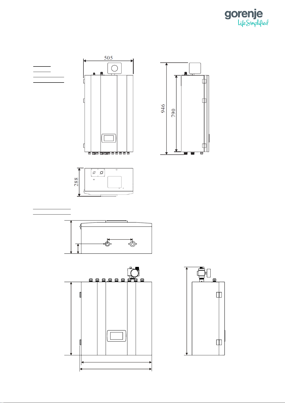
505 x 946 x 288 mm
562 x 686 x 260 mm
Outdoor unit (WxHxD)
1044 × 763 × 414 mm
1258 x 1195 x 407 mm
NET WEIGHT
Indoor unit
50 kg
25 kg
Oudoor unit
75 kg
140 kg
SERIAL INTEGRATED COMPONENTS
Electrical flow heater
6 kW (3ph / 2 stages)
6 kW (3ph / 2 stages)
Circulation water pump - A energy class
Grundfos UPM GEO 25-85 180
Grundfos UPM GEO 25-85 180
3-way diverting valve for DHW tank
Optional external
Optional external
Page 13

6
1.5.2 AEROGOR ECO INVERTER 10A, 13A
MODEL
ECO INVERTER 10A
ECO INVERTER 13A
ErP Energy efficiency class
A++
A++
SCOP 35°C (floor heating) EN 14825
3,83
4,08
P
design
for SCOP EN 14825
6,3 kW
7,46 kW
HEATING MODE (A7/W35)
Heating capacity*
4,57 – 10,50 kW
4,1 -12,2 kW
COP - Coefficient of Performance*
3,80 – 4,71
4,0 - 4,57
Max. temperature of heating water
55 °C
55 °C
Operating range of heat pump - Heating (Ambient temp.)
-25 do +45 °C
-25 do +45 °C
COOLING MODE (A35/W7)
Cooling capacity**
2,60 – 8,00 kW
2,34 – 7,91 kW
Rated input power**
1,10 – 3,50 kW
0,97 – 2,98 kW
EER - Energy Efficiency Ratio**
2,30 – 3,22
2,40 – 3,03
Min. temperature of cooling water
7 °C
7 °C
Operating range of heat pump - Cooling (Ambient temp.)
0 to +65 °C
0 to +65 °C
POWER SUPPLY - SPECIFICATION
Voltage
220-240 V/50 Hz/1 Ph
220-240 V/50 Hz/1 Ph
Rated input power*
0,91 – 3,05 kW
0,96 - 3,02 kW
Fuse for heat pump
1 X 1p/20A/C
1 X 1p/20A/C
Fuse for electrical flow heater
3 X 1p/10A/C
3 X 1p/10A/C
REFRIGERANT SPECIFICATION
Type of refrigerant
R410A
R410A
Refrigerant - mass
1,9 kg
3 kg
GWP (global warming potential)
2088 GWP
2088 GWP
Quantity of hydrofluorocarbons in tonnes of CO2 equivalent
4,051 t CO2 Equiv.
6,264 t CO2 Equiv.
Type of compressor
DC inverter (twin rotary)
DC inverter (twin rotary)
Hermetically sealed equipment (indoor/outdoor unit)
Yes
Yes
Type fo connection between outdoor-indoor unit
Refrigerant connection
Refrigerant connection
Dimensions of refrigerant pipes connectors
3/8” - 1/2”
3/8” - 5/8”
FAN
Fan type
1 x Axial
2 x Axial
Air flow
3100 m3/h
4100 m3/h
Rated power
60 W
2 x 60 W
„ESP“ – External Static Pressure of the Fan (data per piece)
45 W
50 W
WATER SIDE HEAT EXCHANGER
Type
Plate heat exchanger
Plate heat exchanger
Pressure drop
30 kPa
40 kPa
Dimensions of water piping connection
G1"
G1"
ALLOWABLE FLOW - SECONDARY (WATER) SIDE
Min. water flow
1,15 m3/h
1,32 m3/h
Nominal water flow
1,44 m3/h
2,2 m3/h
Max. water flow
2,16 m3/h
2,63 m3/h
SOUND POWER AND PRESSURE LEVEL
Sound power level LwA - Indoor unit
45 dB(A)
46 dB(A)
Sound power level LwA - Outdoor unit
58 dB(A)
59 dB(A)
SOUND PRESSURE LEVEL ON DISTANCE
Indoor unit - 1 m
37 dB(A)
38 dB(A)
Outdoor unit - 1 m
50 dB(A)
51 dB(A)
Outdoor unit - 5 m
36 dB(A)
37 dB(A)
Outdoor unit - 10 m
30 dB(A)
31 dB(A)
Outdoor unit - 15 m
26 dB(A)
27 dB(A)
NET DIMENSIONS
Indoor unit (WxHxD)
505 x 946 x 288 mm
505 x 946 x 288 mm
Outdoor unit (WxHxD)
1044 × 763 × 414 mm
1123 x 1195 x 400 mm
NET WEIGHT
Indoor unit
50 kg
58 kg
Oudoor unit
75 kg
113 kg
SERIAL INTEGRATED COMPONENTS
Electrical flow heater
6 kW (3ph / 2 stages)
6 kW (3ph / 2 stages)
Circulation water pump - A energy class
Grundfos UPM GEO 25-85 180
Grundfos UPM GEO 25-85 180
3-way diverting valve for DHW tank
Optional external
Optional external
Page 14

7
1.5.3 AEROGOR POWER EVI INVERTER 15A, 18A
MODEL
POWER EVI INVERTER 15A
POWER EVI INVERTER 18A
ErP Energy efficiency class
A+
A+
SCOP 35°C (floor heating) EN 14825
3,46
3,42
P
design
for SCOP EN 14825
10,97 kW
13,48 kW
HEATING MODE (A7/W35)
Heating capacity*
6,60 - 14,60 kW
8,2 - 18,0 kW
COP - Coefficient of Performance*
3,80 - 4,46
3,91 - 4,43
Max. temperature of heating water
55 °C
55 °C
Operating range of heat pump - Heating (Ambient temp.)
-25 do +45 °C
-25 do +45 °C
COOLING MODE (A35/W7)
Cooling capacity**
5,56 - 10,00 kW
6,4 - 15,1 kW
Rated input power**
1,57 - 3,82 kW
2,19 – 6,42 kW
EER - Energy Efficiency Ratio**
1,85 - 3,52
2,35 - 2,92
Min. temperature of cooling water
7 °C
7 °C
Operating range of heat pump - Cooling (Ambient temp.)
0 to +65 °C
0 to +65 °C
POWER SUPPLY - SPECIFICATION
Voltage
380-415 V/50 Hz/3 Ph
380-415 V/50 Hz/3 Ph
Rated input power*
1,53 - 4,92 kW
1,53 - 4,92 kW
Fuse for heat pump
1 x 3p/16A/C
1 x 3p/16A/C
Fuse for electrical flow heater
3 x 1p/10A/C
3 x 1p/10A/C
REFRIGERANT SPECIFICATION
Type of refrigerant
R410A
R410A
Refrigerant - mass
6,2 kg
6,6 kg
GWP (global warming potential)
2088 GWP
2088 GWP
Quantity of hydrofluorocarbons in tones of CO2 equivalent
12,946 t CO2 Equiv.
13,780 t CO2 Equiv.
Type of compressor
Scroll EVI DC Inverter
Scroll EVI DC Inverter
Hermetically sealed equipment (indoor/outdoor unit)
Yes
Yes
Type fo connection between outdoor-indoor unit
Refrigerant connection
Refrigerant connection
Dimensions of refrigerant pipes connectors
3/8" - 3/4"
3/8" - 3/4"
FAN
Fan type
2 x Axial
2 x Axial
Air flow
4200 m3/h
4500 m3/h
Rated power
2 x 80
2 x 80
„ESP“ – External Static Pressure of the Fan (data per piece)
50
50
WATER SIDE HEAT EXCHANGER
Type
Plate heat exchanger
Plate heat exchanger
Pressure drop
35
35
Dimensions of water piping connection
G1"
G1"
ALLOWABLE FLOW - SECONDARY (WATER) SIDE
Min. water flow
1,4 m3/h
1,86 m3/h
Nominal water flow
2,56 m3/h
3,09 m3/h
Max. water flow
2,7 m3/h
3,7 m3/h
SOUND POWER AND PRESSURE LEVEL
Sound power level LwA - Indoor unit
47 dB(A)
52 dB(A)
Sound power level LwA - Outdoor unit
68 dB(A)
72 dB(A)
SOUND PRESSURE LEVEL ON DISTANCE
Indoor unit - 1 m
39 dB(A)
44 dB(A)
Outdoor unit - 1 m
60 dB(A)
65 dB(A)
Outdoor unit - 5 m
46 dB(A)
51 dB(A)
Outdoor unit - 10 m
40 dB(A)
45 dB(A)
Outdoor unit - 15 m
36 dB(A)
41 dB(A)
NET DIMENSIONS
Indoor unit (WxHxD)
505 x 946 x 303 mm
505 x 946 x 288 mm
Outdoor unit (WxHxD)
1172 x 1194 x 410 mm
1440 x 1271 x 460 mm
NET WEIGHT
Indoor unit
32 kg
55 kg
Oudoor unit
151 kg
180 kg
SERIAL INTEGRATED COMPONENTS
Electrical flow heater
6 kW (3ph / 2 stages)
6 kW (3ph / 2 stages)
Circulation water pump - A energy class
Grundfos UPM GEO 25-85 180
Grundfos UPMXL GEO25-125 130
3-way diverting valve for DHW tank
Optional external
Optional external
(*) Measured according to standard EN 14511. Heating condition: water inlet/outlet temperature 30°C/35°C, ambient
temperature DB/WB 7°C/6°C.
(**) Measured according to standard EN 14511. Cooling condition: water inlet/outlet temperature 12°C/7°C and ambient
temperature 35°C.
Page 15
8
1.6 DIMENSIONS
1.6.1 INDOOR UNITS
ECO 10 A
ECO 13 A
POWER EVI 15 A
POWER EVI 18 A
ECO COMPACT 10 A
ECO COMPACT 13 A
Unit:mm
260
196.5
570
550
686
561.5
75
Page 16
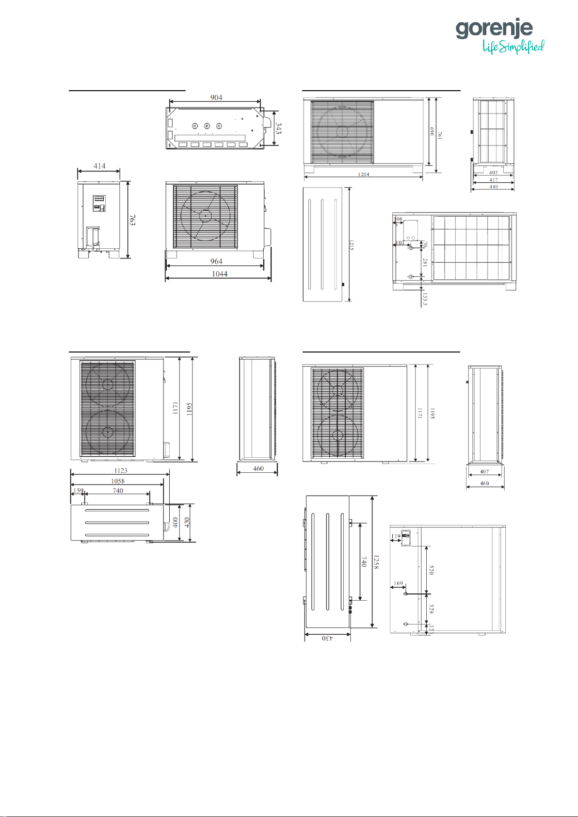
9
1.6.2 OUTDOOR UNITS
AEROGOR ECO INVERTER 10A AEROGOR ECO COMPACT INVERTER 10A
AEROGOR ECO INVERTER 13A, AEROGOR ECO COMPACT INVERTER 13A
Page 17
10
AEROGOR POWER EVI INVERTER 15A AEROGOR POWER EVI INVERTER 18A
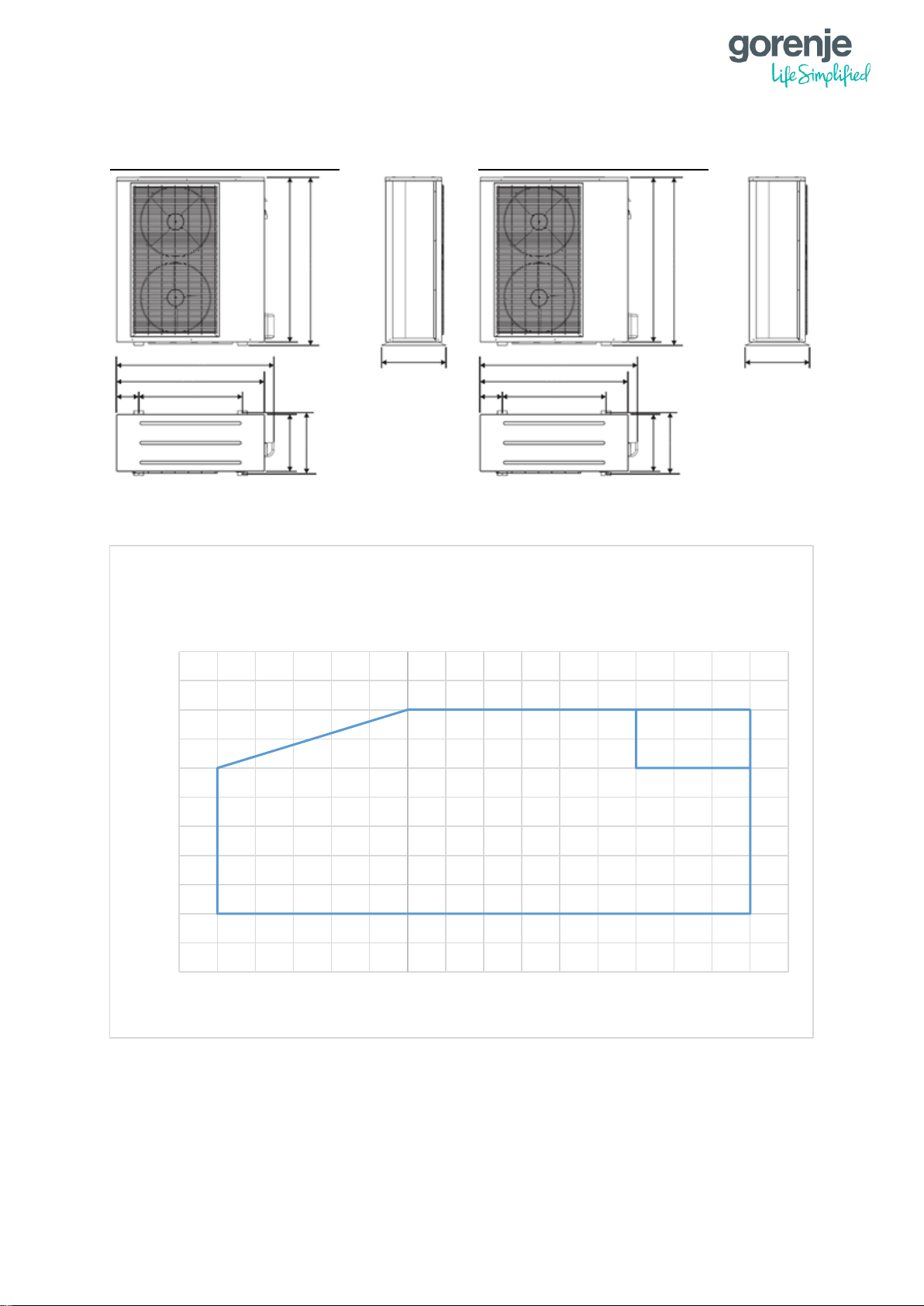
1.7 OPERATING RANGE
10
15
20
25
30
35
40
45
50
55
60
65
-30 -25 -20 -15 -10 -5 0 5 10 15 20 25 30 35 40 45 50
Outlet water temperature [
°C]
Outside Ambient temperature [°C]
Operating range - heating mode:
Aerogor ECO Inverter 10-13 A
Aerogor COMPACT ECO Inverter 10-13 A
ECO
1443
1373
860
222
460
402
460
1272
1294
460
1241
1171
715
182
1171
1193
402
460
Page 18
11
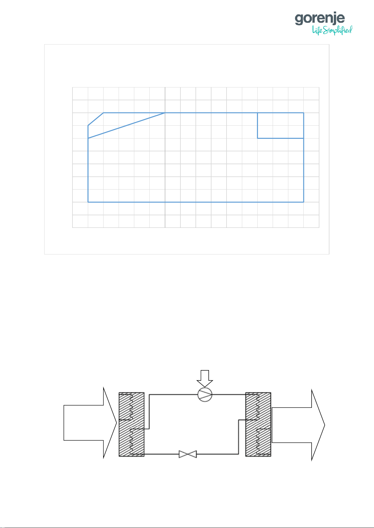
1.8 WORKING PRINCIPLE
A heat pump operates similarly as a refrigerator. In a refrigerator, liquids evaporate due to
received thermal energy from the surrounding air and this energy is emitted at a desired spot
during condensation (Carnot’s cycle). A heat pump works in the opposite direction: it accepts
thermal energy from the surrounding air and emits it in heated premises, using the natural
heat collector of the environment. Ground and surface water, earth’s warmth, solar energy
and ambient air can be used as energy sources. The system is composed of four units:
evaporator, compressor, condenser and damper. Heat energy is transferred via the coolant.
In the evaporator, the coolant receives heat energy and evaporates. In the compressor, the
vapour is compressed, which makes it heat up intensively. This hot vapour transmits thermal
energy from the condenser to the heating water and liquefies. In the damper, the coolant
expands (pressure reduces to the starting pressure, from there it proceeds to the evaporator
and the cycle repeats).
10
15
20
25
30
35
40
45
50
55
60
65
-30 -25 -20 -15 -10 -5 0 5 10 15 20 25 30 35 40 45 50
Maximum outlet water temperture [
°C]
Outside ambient temperature [°C]
Operating range - heating mode:
Aerogor POWER EVI Inverter 15 A
Aerogor POWER EVI Inverter 18 A
Heat from
ambient
Produced
heat for
heating
Electric
energy
ECO
EVI
Compressor
Expansion
valve
Evaporator
Evaporator
Condenser
Condenser
Page 19
12
Inverter heat pumps use variable-speed compressors. Traditional heat pumps use fixed
power/rotation speed compressors. In inverter compressors, the compressor speed
constantly adapts to the heat losses of the room and the energy value of the source (air,
brine or water, depending on the system). In traditional heat pumps, the power of the
compressor is always the same. Compressor starts with full power and when it achieves the
desired values/temperatures, it shuts off and waits until it restarts. Inverter heat pumps work
for a longer period, but with lower power (adjusting to the premises), which means lower
consumption of electric energy.
1.9 MAIN COMPONENTS
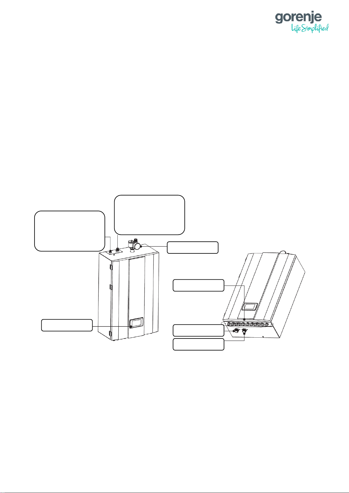
1.9.1 INDOOR UNITS
1.9.1.1 AEROGOR ECO INVERTER 10A/13A AND AEROGOR POWER EVI INVERTER
15A/18A
Refrigerant Connector
ECO 10A: 3/8"
ECO 13A: 3/8"
POWER EVI 15A: 3/8"
POWER EVI 18A: 3/8"
Refrigerant Connector
ECO 10A: 1/2"
ECO 13A: 5/8"
POWER EVI 15A: 3/4"
POWER EVI 18A: 3/4"
Operation panel
Cable gland
Water outlet G1"
Water inlet G1"
Safety valve kit
Page 20
13
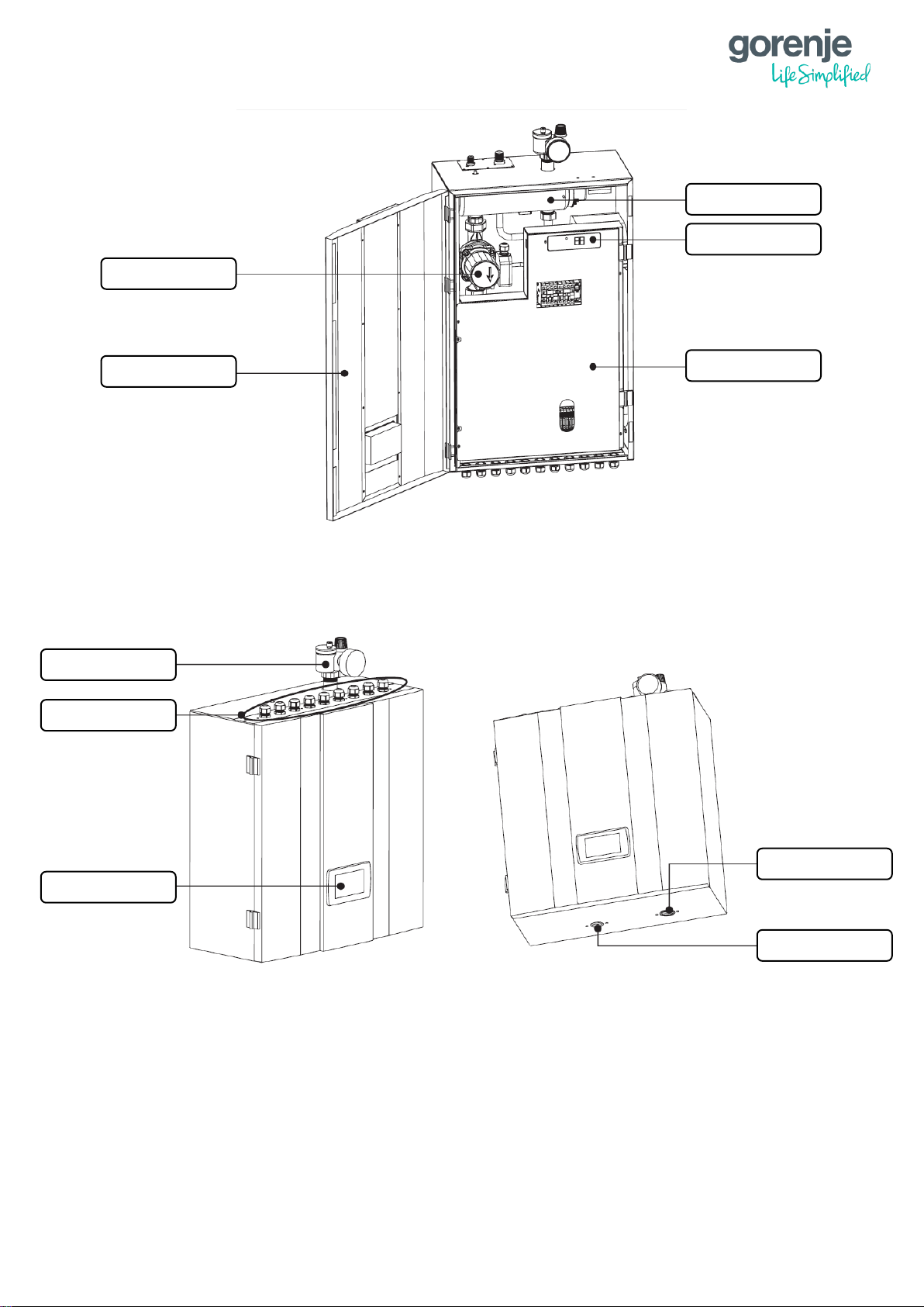
1.9.1.2 AEROGOR ECO COMPACT INVERTER 10A/13A
Operation panel
Cable gland
Safety valve kit
Water inlet G1"
Water outlet G1"
Water pump
Door
Electric heater
Digital thermostat
Electric box cover
Page 21
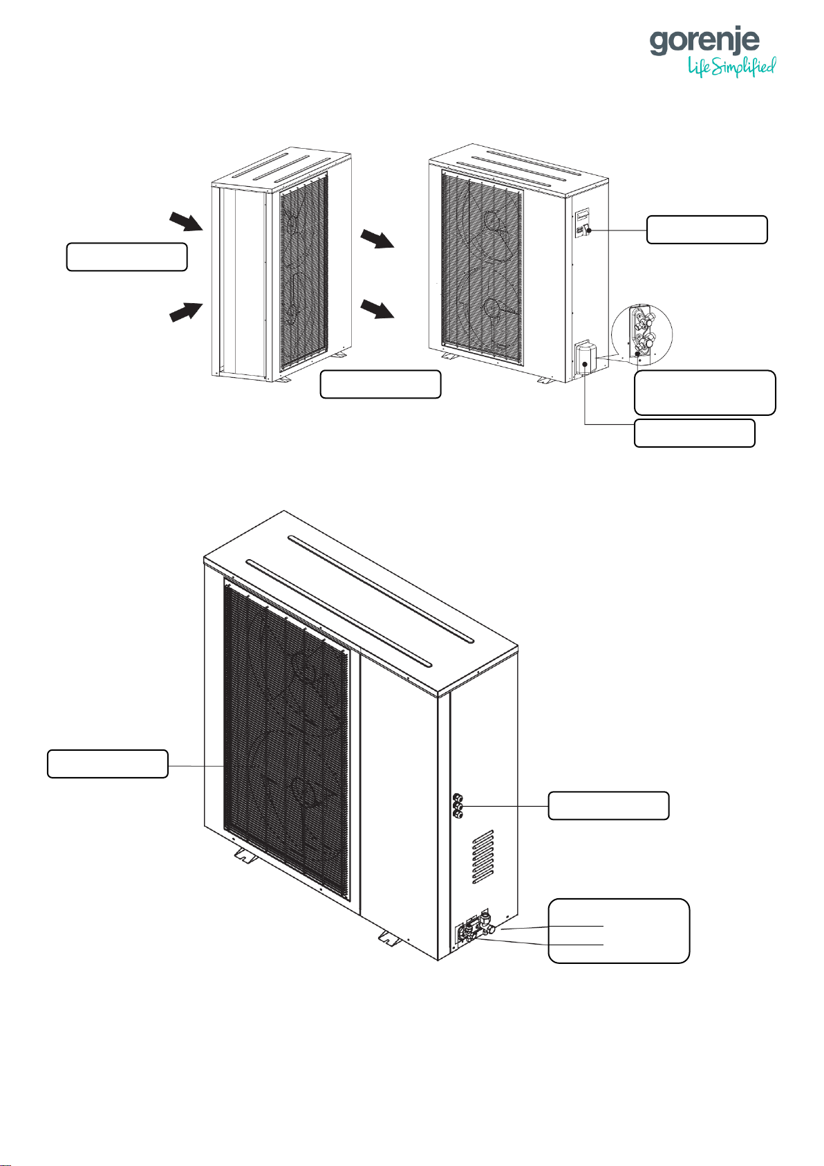
14
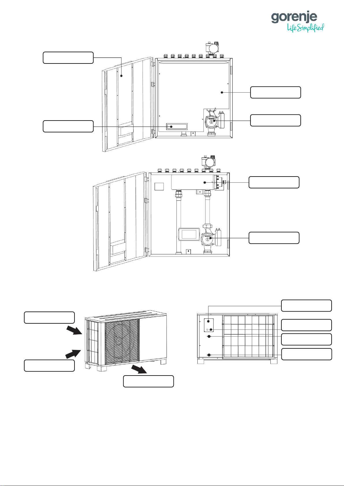
1.9.2 OUTDOOR UNITS
1.9.2.1 AEROGOR ECO COMPACT INVERTER 10A
Electric heater
Water pump
Water pump
Electric box cover
Digital thermostat
Door
Cover
Cable fixture
Air inlet
Air inlet
Air outlet
Water outlet G1"
Water inlet G1"
Page 22
15
1.9.2.2 AEROGOR ECO COMPACT INVERTER 13A
1.9.2.3 AEROGOR ECO INVERTER 10A
Air inlet
Air outlet
Cover
Cable fixture
Water outlet G1"
Water inlet G1"
Air inlet
Air outlet
Handle
Refrigerant connector
3/8" and 1/2"
Valve cover
Page 23
16
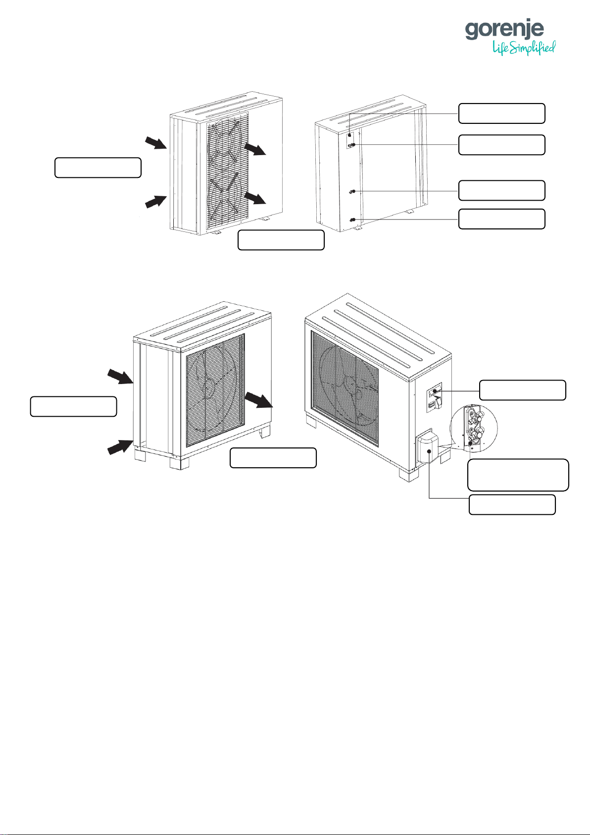
1.9.2.4 AEROGOR ECO INVERTER 13A
1.9.3 AEROGOR POWER EVI INVERTER 15A/ 18A
Handle
Refrigerant connector
3/8" and 5/8"
Valve cover
Air inlet
Air outlet
Refrigerant connector
3/4"
3/8"
Cable gland
Air outlet grill
Page 24
17
2 INSTALLATION
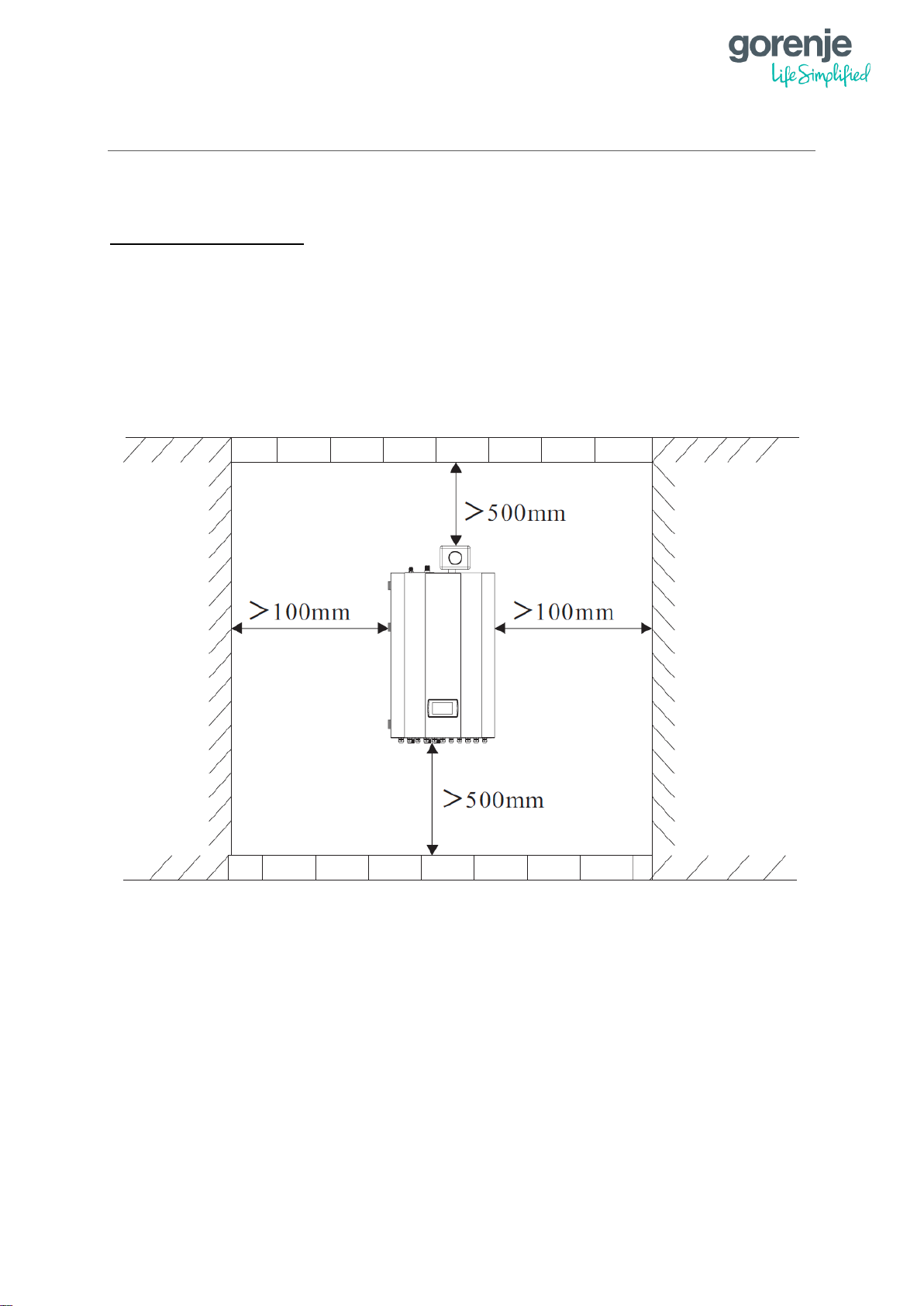
2.1 INSTALLATION OF THE INDOOR UNIT
INSTALLATION NOTES:
1. The indoor unit should be installed indoors and mounted on the wall with water
connections facing downwards.
2. The indoor unit shall be placed in a dry and well-ventilated environment.
3. It is forbidden to install the indoor unit in an environment where there exist volatile,
corrosive or flammable liquids or gases.
4. There should be enough space left around the indoor unit for further maintenance.
Please choose a suitable position to install the indoor unit as follows:
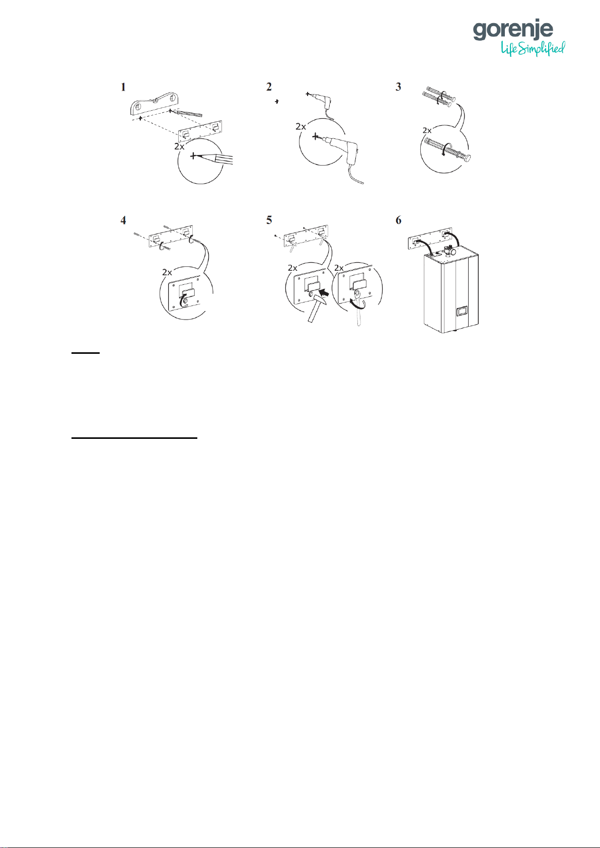
Indoor unit should be mounted on the wall as followed:
1. Take out the expansion bolts and mounting board from the box and put the mounting
board on the wall horizontally.
2. Mark the location of the holes for the bolts on the wall.
3. Drill the holes with proper diameter for the expansion bolts.
4. Unscrew the nuts from the expansion bolts.
5. Fix the mounting board on the expansion bolts a little bit, but don’t be too tight.
6. Use a hammer to pound the expansion bolts into the drilled holes.
7. Fasten the nuts by turning the wrench to fix the mounting board on the wall.
8. Hang the indoor unit onto the mounting board and make sure it’s placed well before
you let go your hands.
9. At this point, the installation is finished.
Page 25
18
Note:
You must choose very firm wall for installation, otherwise the bolts may get loose and
therefore damaging the unit.
2.2 INSTALLATION OF THE OUTDOOR UNIT
INSTALLATION NOTES:
1. The outdoor unit can be located in an open space, corridor, balcony, roof or hanged
on the wall.
2. The outdoor unit shall be placed in dry and well-ventilated environment; If the outdoor
unit is installed in a humid environment, electronic components may get corroded or
short circuited.
3. Outdoor unit mustn’t be installed in an environment where there exist volatile,
corrosive or flammable liquids or gasses.
4. Please don’t install outdoor unit close to bedroom or living room because it produces
some noise when it’s operating.
5. It is recommended to install an awning above the outdoor unit, to protect the snow
from clogging in the air inlet and outlet to ensure normal operation.
6. Please ensure there is drainage system around the location to drain the condensate
water under defrost mode.
7. When installing the unit, tilt it by 1 cm/m to enable rain water drainage.
8. Install outdoor unit far away from the exhaust port of the kitchen to avoid oil smoke
entering into outdoor unit heat exchanger.
9. Please don’t install the indoor and outdoor unit in damp locations. The units should be
free from corrosive and moisture surrounding otherwise the lifetime of the unit might
be shortened.
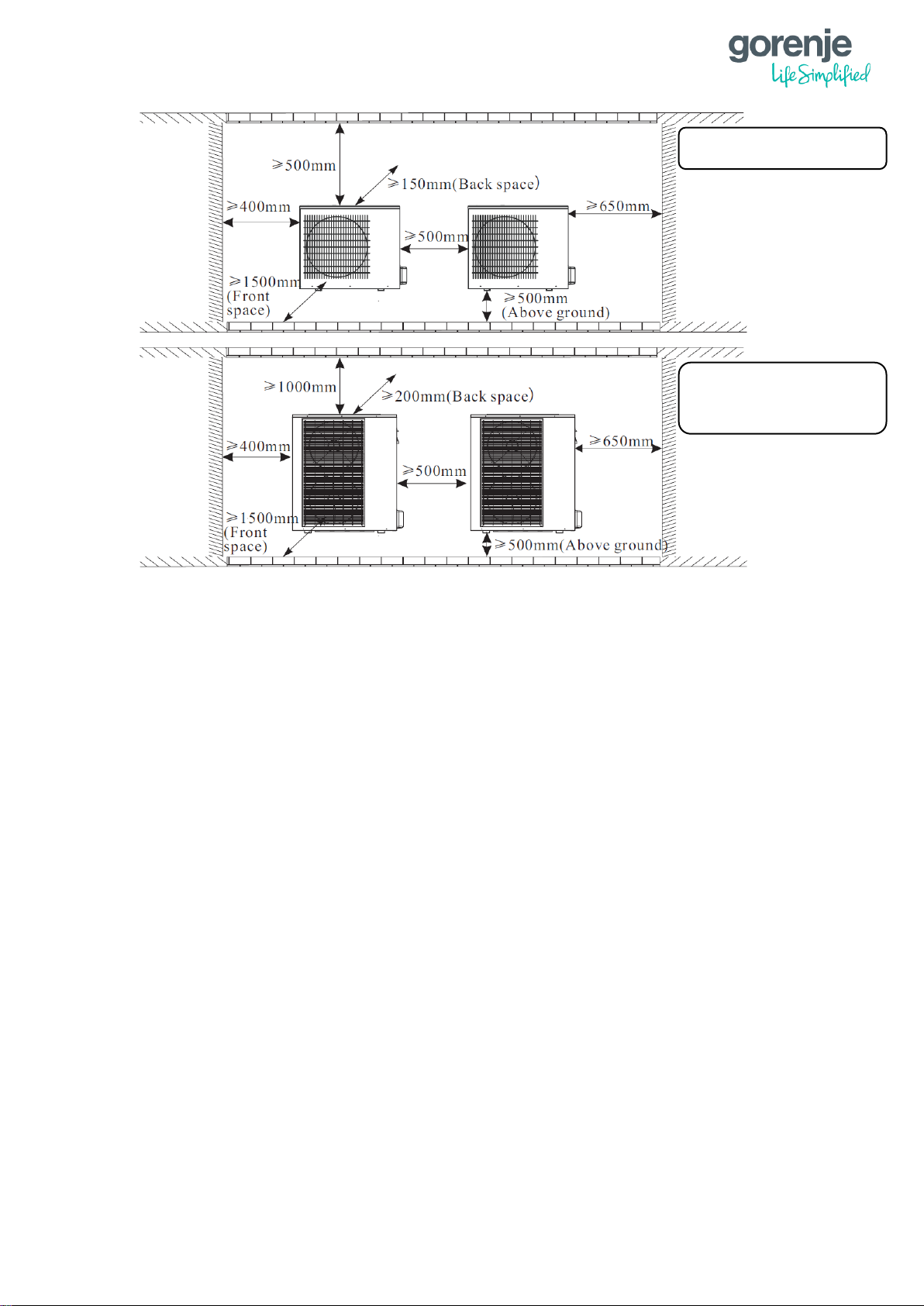
10. Please ensure enough space around the outdoor unit for better ventilation and
maintenance.
Please refer to the illustration below.
Page 26
19
User can either use the dedicated mounting bracket from the supplier or prepare a suitable
bracket for the unit installation. Make sure the installation meets the following requirements:
1. The unit must be installed on flat concrete blocks or a dedicated mounting bracket.
The bracket should be able to support at least 5 times of the unit weight.
2. All nuts must be tightened after the bracket is fixed otherwise it may cause damage to
the equipment.
3. Double check and make sure the installation of the unit is firm enough.
4. The bracket can be made from stainless steel, galvanized steel, aluminium and other
materials as required by the user.
5. Besides the mounting bracket, the user can also install the outdoor unit on two
concrete blocks or a raised concrete platform. Please make sure that the unit is
securely fastened after installation.
6. Please see the dimensions of outdoor unit when choosing a suitable wall bracket.
Hole for piping should lean a little bit to outside (≥ 8 degrees) to keep the rain or condensate
water from flowing back indoors.
AEROGOR ECO INVERTER 10A
AEROGOR COMPACT INVERTER 10A
AEROGOR ECO INVERTER 13A
AEROGOR COMPACT INVERTER 13A
AEROGOR POWER EVI INVERTER 15A
AEROGOR POWER EVI INVERTER 18A
Page 27
20
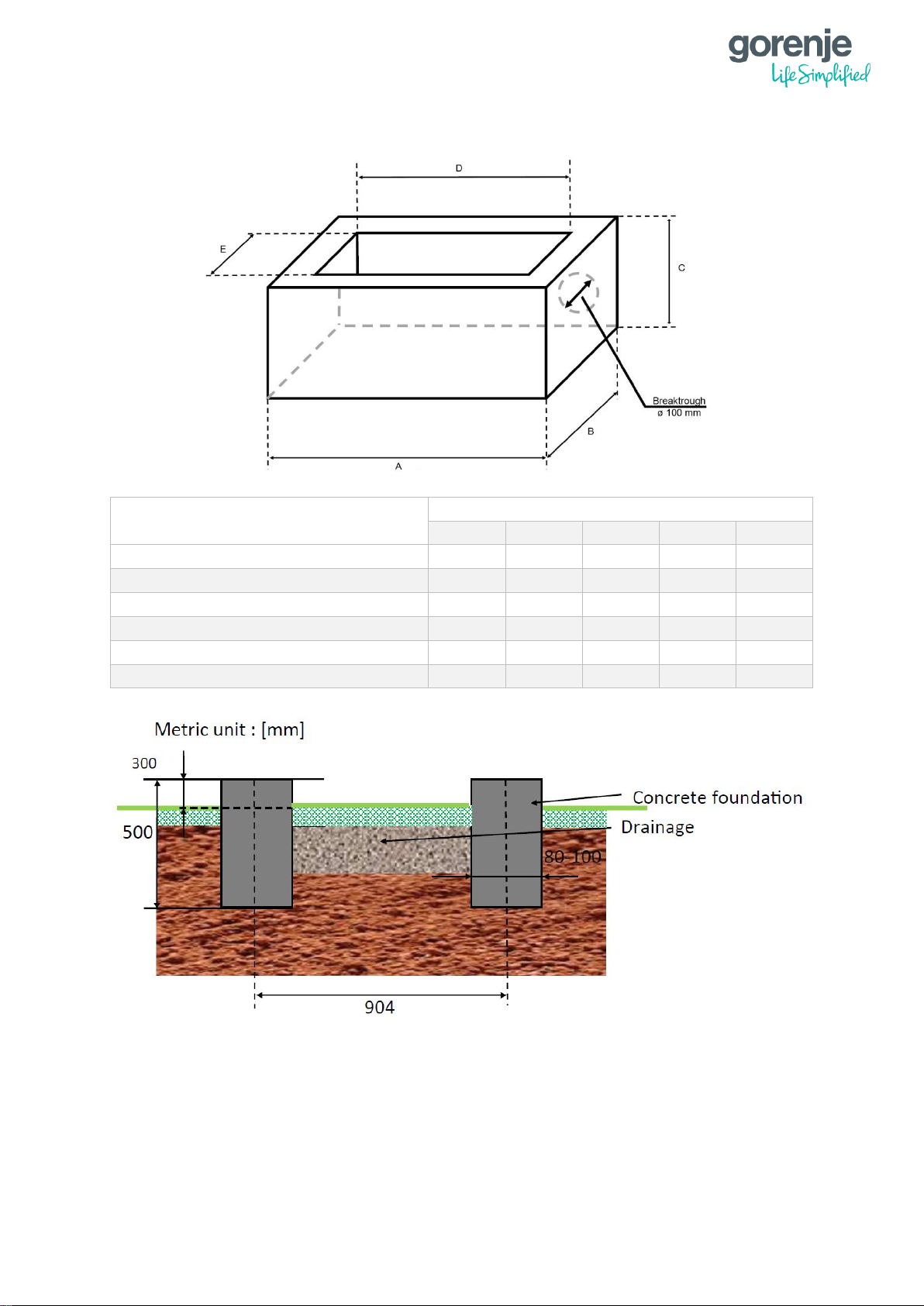
2.3 FOUNDATION
MODEL
SIZE (mm)
A B C D E
ECO COMPACT INVERTER 10A
1390
740
500
1230
580
ECO COMPACT INVERTER 13A
1460
720
500
1300
560
ECO INVERTER 10A
1230
600
500
1070
440
ECO INVERTER 13A
1320
600
500
1160
440
POWER EVI INVERTER 15A
1430
600
500
1270
440
POWER EVI INVERTER 18A
1700
600
500
1540
440
Page 28
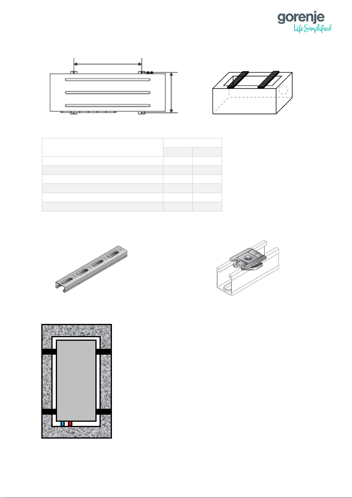
21
MODEL
SIZE (mm)
X
Y
ECO COMPACT INVERTER 10A
1140
340
ECO COMPACT INVERTER 13A
740
430
ECO INVERTER 10A
904
343
ECO INVERTER 13A
740
430
POWER EVI INVERTER 15A
720
430
POWER EVI INVERTER 18A
720
430
2.3.1 INSTALLATION OF C PROFILE AND LEGS
X
MM-C-16 Double installation profile
MM-S Connector for hose clamp
Y
H
Plan view of the heat pump
fixed on the foundation
Page 29
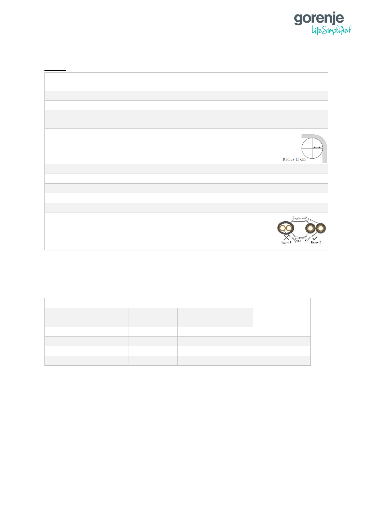
22
2.4 INSTALATION OF THE REFRIGERANT SYSTEM (SPLIT TYPE)
NOTE:
Only certified personnel are allowed to connect and operate with the refrigerant
system.
It is forbidden to start the unit without Evacuating the refrigerant system.
Pipes used for installation must comply with the specifications of the heat pump
Before starting the unit, always check if the refrigerant connections are sealed and
there is no leakage in the system.
The radius at pipe bends must not be less than 15 cm and the pipes
have to be without flaws.
Do not let any dirt in the refrigerant system
Always use tools without flaws.
Always Evacuate the refrigerant to 500 microns or below.
Evacuating the refrigerant system at sub-zero temperatures is forbidden.
Evacuating the refrigerant system at sub-zero temperatures is forbidden.
When insulating refrigerant pipes, insulate each pipe separately.
The split type heat pumps are factory loaded for a specific length. If the length is longer
than factory load, please check that it does not exceed the maximum length shown in the
table below:
For each meter that is longer than the factory load, you must add 40 g of refrigerant.
REFRIGIRANT PIPING LENGTH
CONNECTIONS
HEAT
PUMP
FACTORY
LOAD
MAXIMUM
LENGTH
ADD
ECO Inverter 10A
5 meters
12 meters
40 g/m
1/4" and 1/2"
ECO Inverter 13A
10 meters
15 meters
40 g/m
3/8" and 1/2"
Power EVI Inverter 15A
15 meters
18 meters
40 g/m
3/8" and 5/8"
Power EVI Inverter 18A
15 meters
18 meters
40 g/m
3/8" and 3/4"
Page 30
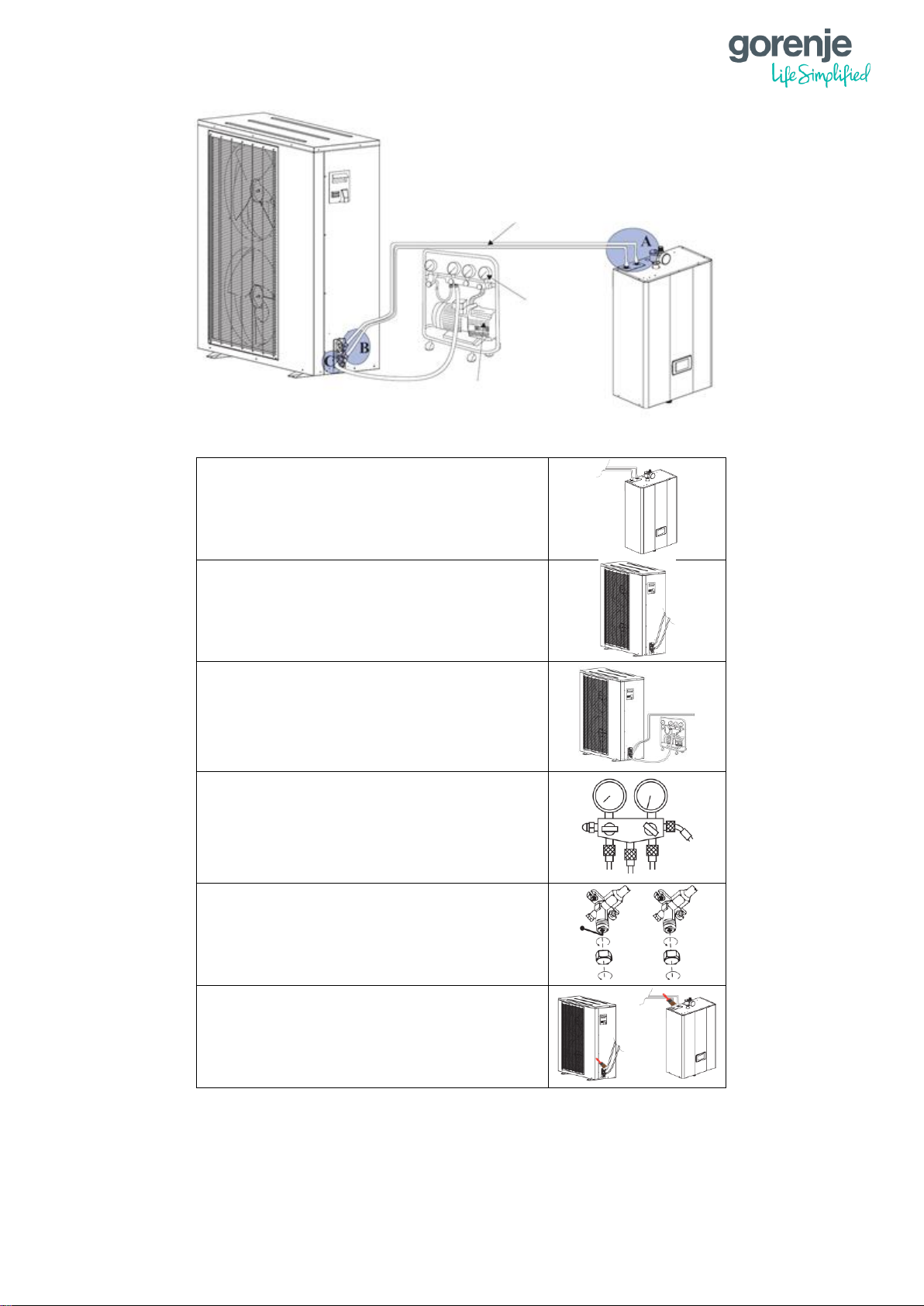
23
A – Connect the refrigerant piping to the
indoor unit.
B - Connect the other end of the refrigerant
pipes to the outdoor unit.
C – Prepare a vacuum pump and a
pressure gauge. Connect one tube of the
pressure gauge to the vacuum pump and
the other one to the high-pressure
refrigerant connector on the outdoor unit.
Open the pressure gauge and start the
vacuum pump to vacuum the unit to 500
microns or below. After that close, the
pressure gauge and stop vacuuming.
Take off the copper nuts off the connectors
and open the valves with hexagon spanner
as much as possible.
Check if there is any leakage with leakage
detector or soap water. If not, remove the
tubes of the gauges and put back the
copper nuts into the valves.
Vacuum pump
Pressure
gauge
Refrigerant pipe
connection
Page 31

24
2.4.1 HEIGHT DIFFERENCE BETWEEN INDOOR AND OUTDOOR UNIT
EXAMPLE FOR AEROGOR ECO INVERTER 10A
A) Outdoor unit is above Indoor unit
Maximum height difference is X m.
Total pipe length distance can be maximum Y m. In case of 7 m (X) height distance
between indoor and outdoor unit, horizontal pipe distance can be maximum 5 m (Z).
In that case is obligatory to integrate 1 siphon.
B) Outdoor unit is below Indoor unit
Maximum height difference is X m.
Total pipe length distance can be maximum Y m. In case of 5 m height distance
between indoor and outdoor unit, horizontal pipe distance can be maximum 7 m (Z).
Page 32

25
• OUTDOOR UNIT IS ABOVE INDOOR UNIT
Model name
Maximum pipe
length (Y)
Outdoor unit is
above Indoor unit
max. height difference
X [m]
Maximum
horizontal pipe
distance/number
of siphons
(Z)
Aerogor ECO
Inverter 10 A
12 meters
7 m
5 meters / 1
siphon
Aerogor ECO
Inverter 13 A
15 meters
7 m
8 meters / 1
siphon
Aerogor POWER
EVI Inverter 15 A
18 meters
7 m
11 meters / 1
siphon
Aerogor POWER
EVI Inverter 18 A
18 meters
7 m
11 meters / 1
siphon
• OUTDOOR UNIT IS BELOW INDOOR UNIT
Model name
Maximum pipe
length (Y)
Outdoor unit is below
Indoor unit
max. height
difference X [m]
Maximum
horizontal pipe
distance/number
of siphons
(Z)
Aerogor ECO
Inverter 10 A
12 meters
5 m
7 meters / 0
siphon
Aerogor ECO
Inverter 13 A
15 meters
5 m
10 meters / 0
siphon
Aerogor POWER
EVI Inverter 15 A
18 meters
5 m
13 meters / 0
siphon
Aerogor POWER
EVI Inverter 18 A
18 meters
5 m
13 meters / 0
siphon
Page 33

26
2.5 INSTALATION OF HYDRAULIC CONNECTIONS (COMPACT
TYPE)
• The pipes used for connection between indoor and outdoor unit must comply with heat
pump requirements and local regulations.
• If city water is used for filling of the heating system, the water quality must comply with
local regulations.
• Pressure in the heating system must be between 1 – 1.8 bar.
• If the heat pump is being installed into an existing hydraulic system, the system must be
cleaned according to standard procedures.
Maximum pipe length for compact type heat pumps is described in the table below:
*For the correct installation please look at the hydraulic schemes for a specific type of heat
pump from your supplier.
HEAT
PUMP
NO BUFFER
WITH BUFFER
CONNECTIONS
ECO COMPACT Inverter 10A
10 meters
20 meters
G1"
ECO COMPACT Inverter 13A
10 meters
20 meters
G1"
Page 34

27
3 ELECTRICAL WIRING
3.1 AEROGOR ECO INVERTER 10A, 13A AND AEROGOR POWER
EVI INVERTER 15A, 18A
3.1.1 INDOOR UNIT
A
HEAT PUMP POWER SUPPLY (FUSE – 20 A 1P C)
A*
HEAT PUMP POWER SUPPLY (FUSE – 16 A 3P C) (POWER EVI INVERTER 15A,
18A)
B
INTERNAL ELECTRICAL HEATERS POWER SUPPLY (FUSE – 3x10 A 1P C)
C
POWER SUPPLY FOR ADDITIONAL ELECTRICAL HEATER FOR DHW TANK –
DEPENDING ON THE TYPE
D
INDOOR TO OUTDOOR POWER CONNECTION (230 V) – 3x2,5 𝑚𝑚2
D*
INDOOR TO OUTDOOR POWER CONNECTION (400 V) – 5x2,5 𝑚𝑚2 (POWER
EVI INVERTER 15 A, 18 A)
E
CONSTANT 230 V RESERVE – MAX. LOAD 100 W
F
CIRCULATING PUMP – HEATING CIRCUIT 1
G
CIRCULATING PUMP – HEATING CIRCUIT 2
H
CIRCULATING PUMP FOR DHW (230 V on P3 during DHW operation)
I
ADDITIONAL ELECTRICAL HEATER FOR DHW TANK
J
DIVERTING VALVE – DHW MODE WITH POWER
K
MODE SWITCHING SIGNAL (see page 65)
Page 35

28
L
INDOOR TO OUTDOOR COMMUNICATION
Cable included in the package – 3x0,75 𝒎𝒎𝟐 Shielded
M
MIXING VALVE 1 (24 V DC Power supply, 0 – 10 V DC Signal)
N
MIXING VALVE 2 (24 V DC Power supply, 0 – 10 V DC Signal)
O
ELECTRICAL UTILITY LOCK (see page 63)
P
EXTERNAL SWITCH INPUT FOR COOLING MODE (0/1) (see page 55)
R
EXTERNAL SWITCH INPUT FOR HEATING MODE (0/1) (see page 55)
Q
EXTERNAL SWITCH INPUT FOR HIGH TEMPERATURE DEMAND (0/1) (see page
60,61)
3.1.2 TEMPERATURE SENSORS
Temperature sensors have quick connectors with marks.
Temperature
sensor
Cable connected
to the PCB
Extension
cable
Page 36

29
3.1.3 CONNECTION BETWEEN INDOOR AND OUTDOOR UNIT
Communication cables shield must be connected on one side, either indoor or outdoor unit.
Page 37

30
3.2 AEROGOR ECO COMPACT INVERTER 10A, 13A
3.2.1 INDOOR UNIT
A
HEAT PUMP POWER SUPPLY (FUSE – 20 A 1P C)
B
INTERNAL ELECTRICAL HEATERS POWER SUPPLY (FUSE – 3x10 A 1P C)
C
POWER SUPPLY FOR ADDITIONAL ELECTRICAL HEATER FOR DHW TANK –
DEPENDING ON THE TYPE
D
INDOOR TO OUTDOOR POWER CONNECTION (230 V) – 3x2,5 𝑚𝑚2
E
CONSTANT 230 V RESERVE – MAX. LOAD 100W
F
CIRCULATING PUMP – HEATING CIRCUIT 1
G
CIRCULATING PUMP – HEATING CIRCUIT 2
H
CIRCULATING PUMP FOR DHW (230 V on P3 during DHW operation)
I
ADDITIONAL ELECTRICAL HEATER FOR DHW TANK
J
DIVERTING VALVE – DHW MODE WITH POWER
K
MODE SWITCHING SIGNAL (see page 65)
L
INDOOR TO OUTDOOR COMMUNICATION
Cable included in the package – 3x0,75 𝒎𝒎𝟐 Shielded
M
MIXING VALVE 1 (24 V DC Power supply, 0 – 10 V DC Signal)
N
MIXING VALVE 2 (24 V DC Power supply, 0 – 10 V DC Signal)
O
ELECTRICAL UTILITY LOCK
P
EXTERNAL SWITCH INPUT FOR COOLING MODE (0/1) (see page 55)
R
EXTERNAL SWITCH INPUT FOR HEATING MODE (0/1) (see page 55)
Q
EXTERNAL SWITCH INPUT FOR HIGH TEMPERATURE DEMAND (0/1) (see page
60,61)
Page 38

31
S
Tuo – Temperature Sensor – Condenser Outlet
T
Tui – Temperature Sensor – Condenser Inlet
U
Tup – Temperature Sensor – Liquid Refrigerant
V
TV2 – Temperature Sensor – Mixing Circuit 2
W
TV1 – Temperature Sensor – Mixing Circuit 1
X
TR – Temperature Sensor – Room temperature
Y
TC – Temperature Sensor – Heating/Cooling (Buffer or direct circuit)
Z
TW – Temperature Sensor – DHW Tank
FS
FS – FLOW SWITCH
3.2.2 TEMPERATURE SENSORS
The temperature sensors do not have quick connectors on both side, instead there are
terminals for connecting the temperature sensors. An Extension cable is included that still
has a quick connector on one side for the Sensor connection and on the other side are
cables for connecting to the Indoor terminal block.
Temperatur
e sensor
Cable connected
to the PCB
Page 39

32
3.2.3 CONNECTION BETWEEN INDOOR AND OUTDOOR UNIT
Cable connection Indoor – Outdoor Unit
• Power Supply (L, N, PE)
• Communication (A, B)
• Temperature sensors (Tui, Tuo, Tup)
• Flow switch (FS, COM)
Note:
All Cables are included (20 meter), except the Power Supply cable. Terminal block of the
Outdoor Unit is on the back side.
Page 40

33
4 CONTROL UNIT
4.1 DESCRIPTION OF SYMBOLS ON THE CONTROL UNIT
a) Operation mode
This symbol shows the operation mode of the heat pump. Two modes are possible:
automatic or manual operation mode. With a short push on this symbol you can
select the operation mode. The recommended setting is automatic mode.
Automatic operation mode
The heat pump automatically switches between heating or cooling the house and
heating of domestic water!
Manual operation mode
In the manual Operation mode, the heat pump only prepares what you have selected
and ignores timers and the ambient temperature!
Only heating of premises (without domestic water, cooling, timers…)
Only cooling of premises (without domestic water, heating, timers…)
Only domestic water (without heating, cooling, timers…)
QuickHeat DHW (Fast heating of the DHW to the set value with the help of additional
heating sources. During QuickHeat, heating of premises is switched off. When the set
value of DHW water is achieved, the unit continues in normal operation).
e) Display of current
operation mode
f) Additional features,
operation modes
g) Warning or Error
h) Power ON/OFF
i) Settings
a) Operation mode
b) Heating or cooling
c) Communication
d) Heating of
domestic water
Page 41

34
If the “Pause” symbol is displayed, the heat pump is manually switched off!
b) Heating or cooling indicator
The symbol indicates that heating or cooling by ambient temperature or thermostat is
activated, or is activated due to manual operation mode!
Heating or cooling is activated or deactivated based on the ambient temperature!
Factory setting of enabled heating or cooling based on the ambient temperature:
Heating – 18 °C
Cooling – 25 °C
These values can be set as you wish.
Example:
Heating activation temperature is set to 18 °C. This means that when the average
ambient temperature exceeds 18 °C, the heat pump will stop heating. The sun
symbol will disappear from the display.
When the average ambient temperature drops below 18 °C, the sun symbol
reappears on the display and the heat pump will reinitiate heating of the premises,
unless an additional thermostat is used. In that case, the heat pump will require the
deactivation of the thermostat.
c) Activating the heating of domestic water
This symbol is visible on the display only when the heat pump is used for heating
domestic water.
The symbol is always visible on the display, unless the domestic hot water timer is
used.
If the domestic water timer is used, a different symbol appears in the domestic water
heating regime.
d) Communication
This symbol displays the communication status of the heat pump.
A light blue symbol indicates normal communication.
A grey symbol indicates loss of communication.
In this case, an error symbol is displayed as well. Please notify an authorized service
person immediately!
e) Display of the current Operation mode
The heat pump displays the current Operation mode.
Heating
Cooling
Heating of domestic water
QuickHeat
Page 42

35
f) Additional features, modes of operation
This symbol appears when the reduced setpoint for heating is on (see chapter
Reduced Setpoint for Heating).
This symbol appears when the “Floor Curing” feature is on.
This symbol appears when the heat pump is in the “Anti-Legionella” mode.
This symbol appears when “Electrical Utility Lock” is on.
This symbol appears when the heat pump is in the “Defrosting” mode.
This symbol appears when the timer for the preparation of domestic water is on
This symbol appears when the timer for heating / cooling is active.
g) Warning or Error
An exclamation mark appears on the screen, cautioning about an error.
• Minor error; considered as a warning. Heat pump operates normally, but an
authorized service person should be informed immediately!
• Major error; to ensure safety of the system and the heat pump, the pump is shut
off. If the “Emergency Operation” feature is on, the heat pump will continue
working, but only with backup heating sources!
Please inform an authorized service person immediately!
h) Power on/off
Heat pump power on/off.
Heat pump on means that the system is active for heating, cooling and preparation
of hot domestic water! The symbol is blue!
Heat pump off means that the system is switched off except for the Anti-freezing
protection which is on! The symbol is grey!
Anti-freezing protection protects the system from freezing. The heat pump
automatically checks the water temperature. If it drops below a certain value,
potentially causing system damage due to system water freezing, it turns on to
increase the water temperature to a safe temperature level.
i) Settings
This button can be used to access menus.
Page 43

36
4.2 DESCRIPTION OF THE TEMPERATURES ON THE CONTROL
UNIT
j) Current and desired temperature of domestic water
Two temperatures are displayed:
Above – Current temperature
Below – Desired temperature
k) Current and desired temperature of heating/cooling
Two temperatures are displayed:
Above – Current temperature
Below – Desired temperature (calculated from the heating curve or desired
temperature).
l) Ambient temperature
The current ambient temperature is displayed.
m) Room temperature
The current room temperature is displayed.
The temperature sensor does not control the operation of the heat pump! It can be
used for the “Room temp. Effect on the Heating Curve” feature, which automatically
reduces or increases the heating curve by a few percent.
n) Temperature of domestic water
The current temperature of domestic water is displayed.
j) Current and
desired
temperature
of domestic
water
k) Current and
desired
temperature
of heating /
cooling
l) Ambient
temperature
m) Room
temperature
n) Temperature
of domestic
water
Page 44

37
5 QUICK SETTINGS
5.1 PARALLEL MOVE OF THE HEATING CURVE
What is a parallel move of the heating curve?
At start-up, the heating curve is adjusted according to the heating system (Floor heating
system, Radiators, Fan coils) and desired room temperature.
The setting can be changed from the Main screen, but only the complete move of the heating
curve and not each reference point separately. The heating curve can be raised or lowered
for 3 °C (-3 to +3).
By raising the heating curve for 2-3 °C would mean an increase of the room temperature for
approx. 1 °C.
The graph below shows a parallel move of the heating curve – lowering of the heating curve
for 2°C
5.1.1 SETTING THE PARALLEL MOVE OF THE HEATING CURVE – HEATING CIRCUIT
1
Parallel move of the
heating curve for -
2°C (Parallel move
set to - 2)
Heating Curve –
normal setting
(Parallel move set to
0)
Ambient temperature (°C)
Flow temperature of the hating system (°C)
By pressing on the Room
temperature display, an
additional window appears.
With buttons ˝+˝ or ˝– ˝ the
heating curve can be changed
for the desired value. Confirm
the setting with button ˝OK˝.
Page 45

38
5.1.2 SETTING THE PARALLEL MOVE OF THE HEATING CURVE – HEATING CURVE
2
PARALLEL MOVE OF THE HEATING CURVE 2 IS AVAILABLE ONLY WHEN USING TWO
HEATING CIRCUITS!
First the window for parallel move of the first heating circuit appears. To access the setting of
the parallel move for the second heating circuit press . Second page appears with the
setting for the second heating circuit.
With buttons ˝+˝ or ˝– ˝ the heating curve can be changed for the desired value. Confirm the
setting with button ˝OK˝.
5.1.3 SETTING THE DHW TEMPERATURE
By pressing on the DHW temperature, an additional window appears.
With buttons ˝+˝ or ˝– ˝ the DHW set temperature can be changed for the desired value.
Confirm the setting with button ˝OK˝.
Domestic hot water settings depend on the user’s habits.
The recommended setting for domestic hot water is between 47 °C and 50 °C.
Traditional systems (boilers) use smaller domestic water storage tanks, so the temperature
must be significantly higher than in a heat pump system, which causes higher costs of
domestic hot water preparation!
In principle, a heat pump system is planned to store 50 litres of water per person. This
means that a family of four needs a minimum of 200 litres of hot water per day.
Note:
Mixing of cold and warm water in a mixing tap differs according to the systems of how
domestic water is heated.
If the traditional domestic water heating system is used, less hot water is mixed with cold
than in a heat pump system.
By pressing on the room temperature
display, an additional window
appears.
OK
Cancel
System 1 Heating Curve Parallel Move 2: 0°C
OK
Cancel
Desired temperature: 47°C
Page 46

39
In a heat pump system, a larger quantity of hot water is mixed with cold water, as the volume
is larger and the temperature is lower (contributing to lower costs) than in the traditional
system, where the water volume is 2-3 times smaller.
5.2 SETTING THE FIXED TEMPERATURE OF HEATING CIRCUIT
This quick setting is available only when one or both heating circuits are used without heating
curves.
5.2.1 SETTING THE FIXED TEMPERATURE FOR THE FIRST HEATING CIRCUIT
By pressing on the temperature below the line, beside the sun symbol, an additional window
will appear.
With buttons ˝+˝ or ˝– ˝ the fixed temperature for the first heating circuit can be changed for
the desired value. Confirm the setting with button ˝OK˝.
5.2.2 SETTING THE FIXED TEMPERATURE FOR THE SECOND HEATING CIRCUIT
By pressing on the temperature below the line, beside the sun symbol, an additional window
will appear. Press the arrow in the down right corner to access the setting for the second
heating circuit.
With buttons ˝+˝ or ˝– ˝ the fixed temperature for the second heating circuit can be changed
for the desired value. Confirm the setting with button ˝OK˝.
Page 47

40
6 USER INTERFACE
6.1 ARRANGMENT OF MENUS
The control unit has two levels of menus. The first page of the menus is intended for the end
user, and the second page is for the authorized service person or for install settings with
some excluded exceptions.
6.2 MENU ACCESS
By pressing you can access the menus with settings for the end user, as well as the
service settings (see image below)!
Service settings are protected by a service code. The end user is not allowed access to
these settings. The user can view the settings but is not allowed to change them!
User menu Service menu
Page 48

41
6.3 SETTINGS
Heating
The heat pump enables two heating circuits, meaning that it can control two different
temperature modes. Heating/cooling circuit 1 and Heating/cooling circuit 2
When only one heating circuit is in use, the heating settings are defined in the menu
“Heating/cooling circuit 1“!
6.3.1 Heating/Cooling Circuit 1
Page 49

42
6.3.1.1 Heating/Cooling Stops Based on Water ∆T
Temperature setting that allows overheating of the heating system for the set value.
The recommended setting is 2 °C! This enables efficient operation of the Inverter technology
and brings the highest savings.
Please note, that we allow the Heat Pump to overheat the system, to maintain a low working
speed and to avoid a frequent stopping and starting of the compressor.
6.3.1.2 Heating/Cooling Restarts Based on ∆T
The compressor restarts based on the set values of heating/cooling circuits.
The recommended value is 2 °C. This enables efficient operation of the Inverter technology
and brings the highest savings.
6.3.1.3 ∆T Compressor Speed Reduction
This setting tells the system when will the compressor start lowering its working speed. The
recommended value is 2 °C. This enables efficient operation of the Inverter technology and
brings the highest savings.
For example:
If the set/calculated temperature is 30°C and the ˝∆T COMPRESSOR SPEED REDUCTION˝
is set to 2°C, the compressor will work at its max working speed (check chapter ˝Max
Compressor Working Speed˝) till it reaches 28°C. At a 28,1°C and above the compressor
speed will start to decrease towards the lowest working speed of the compressor.
6.3.1.4 Set temp. For cooling
Setting the desired cooling water temperature of the first cooling circuit is set (the second
circuit is set in the menu “Heating/Cooling Circuit 2”).
6.3.1.5 Heating Curve
The heating curve mode is based on the condition that the lower the ambient temperature is,
the higher the water temperature for the heating of facility is. This heating curve mode can
help the heat pump to achieve a higher COP (efficiency rate) and increase the feeling of
comfort in the house.
As the level of home insulation and people’s feeling of cold can differ, the factory set curve
may not be appropriate for everybody. The heating curve may be set according to customers
needs.
The basic setting of the heating curve is made upon the first start-up of the heat pump. The
start-up must be performed by an authorized service person!
The basic setting is always adjusted according to the system that is installed (underfloor
heating, radiators, convectors (Fan Coil)). To determine the basic heating curve, we also
need to take into account the insulation of the facility!
The heat pump enables two heating circuits with different heating curves.
Page 50

43
6.3.1.6 SETTING THE HEATING CURVE FOR THE FIRST HEATING CIRCUIT
Heating curve is set on page 3 of the “Heating/Cooling Circuit 1” menu!
PAGE 3
Tsh – Space heating temp.; T(Ta) – Ambient temp.
Ta1
Ta2 Ta3 Ta4
Ta5
Tsh1
Tsh2
Tsh3
Tsh4
Tsh5
NOTE:
It is recommended to reset only the space heating water temperatures (figure above on
the right). Resetting ambient temperatures for the heating curve affects both heating
circuits.
EXAMPLE
Example:
The customer wants the room temperature to be 21 °C, but the heat pump heats the rooms to 22 °C. In
this case the heating curve must be lowered. On page 3, all temperatures need to be lowered by 2-3 °C,
which means that the room temperature will be lower by 1 °C. If the room temperature is lower than the
desired temperature, the temperature values must be increased.
Page 51

44
6.3.1.7 Room temp. effect on Heating Curve
When the temperature sensor ˝TR˝ is mounted in the living area, this function can make
small corrections of the heating curve, depending on the set “Ideal Room Temp. in Heating”.
Note:
This feature does not mean temperature control by room temperature, but only a correction
of the heating curve!
If this feature is on and the temperature in the room (where the TR room temperature sensor
is located) still exceeds the set ideal value, the heating curve settings should be reset!
6.3.1.8 Ideal Room temp. in Heating
Relates to parameter (6.3.1.6).
The setting is active only when the feature “Room Temp. Effect on Heating Curve” is
enabled.
6.3.1.9 Ideal Room temp. in Cooling
Relates to parameter (6.3.1.6).
The setting is active only when the feature “Room Temp. Effect on Heating Curve” is on
6.3.1.10 Set Temperature for heating – without heating curve
Set temperature for the heating water system – without heating curve.
When the heating curve is disabled, the heat pump operates with fixed system heating water
temperature.
Weather-related control of the heating circuit is disabled, which can lead to higher heating
costs!
NOTE:
The parameters in grey are protected by a service code!
6.3.1.11 Low Temperature Limit
This is for setting the lowest possible temperature that the end customer can set, without
accessing the service level. This setting applies for the heating mode and cooling mode.
6.3.1.12 High Temperature Limit
This is for setting the highest possible temperature that the end customer can set, without
accessing the service level. This setting applies for the heating mode only.
Default setting is 40°C, meaning if a system with higher desired temperatures is used
(radiators, Fan-coils…) the Limitation must be increased.
6.3.1.13 Mixing Valve
Enabling or Disabling the Mixing Valve for the first Heating/Cooling Circuit (Heating/Cooling
Circuit 1).
A check in a box means that the Heating/Cooling Circuit 1 uses a Mixing Valve for the
Circuit.
Please note that if the Mixing Valve is Enabled a temperature sensor (TV1) must be added
after the Mixing Valve.
Page 52

45
6.3.2 Heating/Cooling circuit 2
6.3.2.1 Heating/cooling Circuit 2
A check in a box means that the heating/cooling circuit 2 is on.
6.3.2.2 Set temp. for Cooling
Setting the desired space cooling water temperature in Cooling Circuit 2.
The desired temperature of Cooling Circuit 2 is set.
6.3.2.3 Set Temp. For Heating – without heating curve
Set temperature of space heating water– without heating curve.
When the heating curve is off, the heat pump operates with fixed space heating water
temperature.
Weather-related control of the heating circuit is off, which can lead to higher heating costs!
6.3.2.4 Mixing Valve
Enabling or Disabling the Mixing Valve for the second Heating/Cooling Circuit
(Heating/Cooling Circuit 2).
A check in a box means that the Heating/Cooling Circuit 2 uses a Mixing Valve for the
Circuit.
If the Mixing Valve is Enabled, a temperature sensor (TV2) must be added after the Mixing
Valve.
Page 53

46
NOTE:
If the second heating circuit is active and the room thermostat is not used, a wire must be
placed between TH and COM. If a wire is not placed between TH and COM, the heat pump
will heat the buffer tank according to the lower temperature demand.
6.3.2.5 Heating Curve
The heating curve mode is based on the condition that the lower the ambient temperature is,
the higher the water temperature for the heating of facility is. This heating curve mode can
help the heat pump to achieve a higher COP (efficiency rate) and increase the feeling of
comfort in the house.
As the level of home insulation and people’s feeling of cold can differ, the factory set curve
may not be appropriate for everybody. The heating curve may be set according to customers
needs.
The basic setting of the heating curve is made upon the first start-up of the heat pump. The
start-up must be performed by an authorized service person!
The basic setting is always adjusted according to the system that is installed (underfloor
heating, radiators, convectors (Fan Coil)). To determine the basic heating curve, we also
need to take into account the insulation of the facility!
The heat pump enables two heating circuits with different heating curves.
Tsh – Space heating temp.; T(Ta) – Ambient temp.
Ta1 Ta2 Ta3 Ta4 Ta5
Tsh1
Tsh2
Tsh3
Tsh4
Tsh5
NOTE:
It is recommended to reset only the space heating water temperatures (figure above on
the right). Resetting ambient temperatures for the heating curve affects both heating
circuits.
Page 54

47
6.3.2.6 SETTING THE HEATING CURVE FOR THE SECOND HEATING CIRCUIT
Heating curve is set on page 2 of the “Heating/Cooling Circuit 2” menu!
6.4 DHW SETTINGS
EXAMPLE
Example:
The customer wants the room temperature to be 21 °C, but the heat pump heats the rooms to 22 °C. In
this case the heating curve must be lowered. On page 3, all temperatures need to be lowered by 2-3 °C,
which means that the room temperature will be lower by 1 °C. If the room temperature is lower than the
desired temperature, the temperature values must be increased.
Page 55

48
6.4.1.1 Setpoint DHW
Setting of the desired temperature for domestic water.
6.4.1.2 DHW Restart ∆T Setting
Domestic hot water restart setting.
Example:
Desired temperature of domestic water is 47 °C, and the domestic hot water restart ∆T
setting is 5 °C. (47–5=42)
This means that the heat pump will restart the heating of domestic water when the
temperature drops below 42 °C!
Recommended domestic hot water restart ∆T setting is 5 °C!
6.4.1.3 Shifting Priority
The heat pump has absolute priority for the preparation of domestic hot water. With this
feature, the priority adjusts to the heat losses when the ambient temperature reaches a
certain point.
This feature is used in new buildings that still lack insulation and that will be without
insulation for at least one heating season.
6.4.1.3.1 Enabling or Disabling the Shifting Priority function:
Disabled (default setting) – the Heat Pump will switch to Heating mode only when the
desired DHW temperature is reached.
Enabled – the Heat Pump will decide based on the temperatures of the heating system if it
should switch to heating although the DHW set temperature is not reached yet.
For example:
Set temperature for DHW is 47°C and the Heat Pump is currently working in DHW mode.
The actual DHW temperature is 44°C, meaning it still has to heat up the DHW for another
3°C, before it can switch to heating mode (heating the House). In that moment, the Unit sees
that the temperature of the Heating water for the heating system is dropping for a certain
value, meaning it is a high risk of undercooling the house. It switches to Heating mode to
provide heat to the house. When the temperature is in safe level, or the max set time for
heating is exceeded, the Heat Pump switches back to DHW mode to heat up the DHW to the
desired value, before it switches back to Heating mode.
6.4.1.3.2 Shifting Priority Starting Temperature
Only valid if Shifting Priority enabled!
Setting the Ambient temperature to activate the Shifting Priority Function.
If the Shifting Priority Function is enabled it will not be active before the Ambient temperature
falls below a certain value (Shifting Priority Starting temperature).
6.4.1.4 Sanitary Water Min. Working Hours
Only valid if Shifting Priority enabled!
This setting is set in Minutes!
The Heat Pump will try to heat up the DHW for a minimum time before it switches to Heating,
even if all other conditions for Shifting Priority are met.
6.4.1.5 Heating Max. Working Hours
Only valid if Shifting Priority enabled!
This setting is set in Minutes!
Page 56

49
When the Heat Pump switches to Heating mode in Shifting priority mode, it will allow the unit
to stay in Heating mode only for a certain time, before it switches back to heat up the DHW.
6.4.1.6 Allowable temp. Drift in Heating
Only valid if Shifting Priority enabled!
Setting for the max. Temperature drift in heating system during DHW heating mode. Only
when this value is exceeded, the Unit will switch to heating.
6.4.1.7 DHW Backup Heater for Shifting Priority
Only valid if Shifting Priority enabled!
Disabled – Backup heater will work only according to the normal back-up stings.
Enabled – Backup Heater will help to faster heat up the DHW.
6.4.1.8 DHW ECO Operation
Enable or Disable this function.
Disabled (default setting) – normal operation of DHW working mode
Enabled – the compressor speed never exceeds 50% of the compressor working speed,
which is determent by the ambient temperature (see chapter ˝Compressor Speed˝).
NOTE:
In normal operation (DHW ECO Operation – Disabled), the compressor speed is limited by
the Ambient temperature, meaning that the compressor speed will decrease when ambient
temperature is Increasing.
6.4.1.9 Ambient Temp. to Start DHW ECO Operation
Setting the Ambient temperature when the DHW ECO Operation function will be active.
Please note, that if the Ambient temperature is higher than this setting, the DHW ECO
Operation will not be active!
6.5 DHW STORAGE
Page 57

50
If the fields are green, domestic water heating is on.
If the fields are grey, it means the heat pump is not heating domestic water.
6.5.1 Sanitary Hot Water Storage Function
Feature on/off.
A check in the box means that the feature is on.
This feature enables water preparation at a certain time and day. It is set for each day of the
week individually.
6.5.2 Sanitary Hot Water Storage Timer
Setting domestic water heater timer!
6.5.3 Reheating Function
Feature on/off.
A check in the box means that the feature is on.
The feature enables the setting of a second temperature mode for domestic water heating.
This means that it enables two different temperatures of domestic water at various times in
an individual day of the week.
Setting of a second temperature of domestic hot water corresponds to the parameter
“Reheating Set Temp.”.
6.5.4 Reheating Function Timer
Setting the second timer for the heating of domestic hot water!
If the fields are green, domestic water heating is on.
If the fields are grey, it means the heat pump is not heating domestic water.
6.5.5 Reheating Set Temp.
Setting the desired temperature for the second mode of heating of domestic water.
This temperature will be the default temperature for domestic water heating in the “double
mode”.
The temperature can be lower or higher than the primary setting of the desired domestic hot
water temp.!
Note:
If timers overlap, the heat pump will take into account the higher level of desired domestic
water temperature!
Page 58

51
6.5.6 Reheating Restart ∆T Setting
For the second temperature mode for heating domestic water, this parameter is used to set
the DHW restart. The recommended setting is 5 °C.
Example:
Desired domestic hot water temperature is 45 °C, and the DHW restart setting is 5 °C. (45–
5=40).
Heat pump will start reheating domestic water once it drops below 40 °C.
6.6 REDUCED SETPOINT
6.6.1 Reduced Setpoint
Feature on/off.
A check in the box means that the feature is on.
The feature lowers water temperature by the set value for both heating circuits in the set
time. The main purpose is to lower room temperature at night.
6.6.2 Temp. Drop/Rise
The space heating water temperature drop/rise is set for both heating circuits.
6.6.3 Timer for Reduced Setpoint Function
Timer for feature activation is set!
If the fields are green, domestic water heating is on.
If the fields are grey, it means the heat pump is not
heating domestic water.
Page 59

52
6.6.4 Quiet Operation
Feature on/off.
A check in the box means that the feature is on.
Quiet operation means that the heat pump tries to operate with the lowest possible rpm of
compressor and fans, so that noise is reduced in the night time.
The maximum deviation from the desired space heating water temperature is set.
6.6.5 Allowable Temp. Drifting
The maximum allowable space heating water temperature drifting is set for both circuits
when the “Quiet operation” feature is on.
6.6.6 Timer for Quiet Operation
Timer for the Quiet Operation Feature!
If the fields are green, the feature is on.
If the fields are grey, it means the feature is off – normal
operation!
Note:
If the timers “Reduced Setpoint” and “Quiet Operation” overlap, the heat pump will operate in
the quiet mode with an additional temperature drop, as set in the “Temp. Drop/Rise”.
6.7 ANTI – LEGIONELLA
6.7.1 Anti – Legionella Program
Feature on/off.
A check in the box means that the feature is on.
For the Anti-legionella feature to operate, an electric heater must be installed in the DHW
tank!
Page 60

53
6.7.2 Day and Time
The day and time for the feature to be switched on is set here.
The recommended setting is Monday at 2:00 AM.
6.7.3 Setpoint
The desired temperature (setpoint) of the Anti-legionella feature is set here.
6.7.4 Duration
Here you can determine how long the heat pump should maintain the desired temperature in
the Anti-legionella programme!
6.7.5 Finish Time
If the heat pump cannot heat the domestic water in the set time, the programme is
terminated and an error message appears on the display.
6.8 VACATION MODE
6.8.1 Vacation Mode
A check in the box means that the feature is on.
This feature can be used for the time when you are absent and there is no need for heating
or hot water. The date of departure (start date) and date of arrival (finish date) is set and the
desired heating and water temperature drop for the duration of your vacation.
Page 61

54
6.8.2 Sanitary Hot Water Temp. Drop during Vacation Mode
Setting domestic hot water temperature drop during the vacation mode.
6.8.3 Heating Water Temp. Drop during Vacation Mode
Setting heating water temperature (heating) drop during the vacation mode
6.8.4 Vacation Start Date
Setting the start date of vacation.
6.8.5 Vacation Finish Date
Setting the finish date of vacation.
6.9 USER MANAGEMENT
6.9.1 Permission Level
Enter the Service Password to enter the Service / Installer level.
Installer code: 87654321
6.9.2 Heating/Cooling ON/OFF timer
Disabled (default setting) – Normal operation
Enabled – The Heat Pump Will Heat and Cool only according to the setting of a Timer. In the
other time, it will be only in Antifreeze protection mode.
Please note, that this has no influence on the DHW mode.
SETTING THE TIMER:
Green fields mean that heating/cooling depending on the
ambient temperature is on.
Gray fields mean that heating/cooling depending on the
ambient temperature is blocked.
Page 62

55
6.9.3 Language
Setting the language of the interface.
6.9.4 Set Date and Time
Setting the time and date.
6.9.5 Distribution System Setting
This is to determine the working logic of the Diverting Valve, which way the water will flow in
Heating mode, Cooling mode and DHW mode.
In this Parameter, two options are possible:
W / HC (Sanitary Hot Water / Heating + Cooling) – When in DHW mode the Diverting
Valve will be in position 1, sending the system water in one direction. When in Heating or in
Cooling mode the Diverting Valve will be in position 2, sending the system water in the other
direction.
WH / C (Hot Water + Heating / Cooling)
When in DHW mode or Heating mode the Diverting Valve will be in position 1, sending the
system water in one direction. When in Heating mode the Diverting Valve will be in position
2, sending the system water in the other direction.
6.9.6 Save Current Settings
Saving all the settings at the end of a Start-Up. By saving this setting, the end customer can
recall them by pressing ˝Load Saved Settings˝, meaning all settings will reset to the settings
saved during Start-Up.
6.9.7 Load Saved Settings
Reset all settings to “Install Settings”.
All settings are reset to the settings stored during the last intervention by an authorized
service person.
6.9.8 Switch to Factory Settings
Unit will reset to the factory settings.
Heating mode
Cooling mode
DHW mode
Common
line
Cooling mode
DHW mode
Heating mode
Common
line
Page 63

56
6.10 MODE SETTINGS
6.10.1 Sanitary Hot Water
Disabled (Default setting) – Unit will not work for Sanitary Hot Water (DHW)
Enabled - Unit will work for Sanitary Hot Water (DHW)
6.10.2 Heating
Disabled – Unit will not work for Heating mode
Enabled (Default setting) - Unit will work for Heating mode
6.10.3 Cooling
Disabled (Default setting) – Unit will not work for Cooling
Enabled - Unit will work for Cooling
6.10.4 Basic Operation Modes
This function is not ready yet!
DO NOT ENABLE THIS FUNCTION! It may cause damage to the system and the Unit itself
if enabled!
Page 64

57
6.10.5 Cooling and Heating Switch
Setting how will the Unit decide to start heating or cooling. Default setting is ˝Ambient
temperature˝.
Please note, that this function does not influence the working of the DHW mode.
Possible settings are:
OFF – Unit will not automatically switch to heating or cooling. Only manual switching
Ambient Temp. (Default setting) – Unit switches automatically from Heating mode and
Cooling mode according to the average ambient temperature. Please refer to parameters
6.9.6 and 6.9.7 for temperature setting.
External Signal Control – The Unit will not consider the ambient temperature setting for
heating and cooling switch! It will judge based on a signal received to contacts HS - COM
(heating signal) and CS – COM (cooling signal).
A potential free signal must be used! No voltage must be present!
Please note if signal for heating in high ambient temperatures (when heating is not anymore
needed) is present, the Heat Pump will run in Heating mode!
External Signal Control + Ambient Temp.
This setting means, that the Unit will work only for Heating and Cooling with signal (HS –
COM or CS – COM), but will take into account the Ambient temperature.
6.10.6 Ambient Temp. To Start Heating
Setting the Ambient temperature to start Heating mode.
Default setting is 18°C.
Example:
The set temperature to start heating is 18 °C.
The heat pump will heat the facility depending on the set values (heating curve or constant
space heating water temperature, depending on the settings), if the ambient temperature
drops below 18 °C.
When the ambient temperature rises above 18 °C, the heat pump will automatically stop
heating the facility.
It will resume heating when the ambient temperature drops below 18 °C.
Note:
To prevent too frequent switches between operation and non-operation, the control unit
monitors the current temperature and temperature within a certain period and decides based
on this whether heating should be activated or blocked.
Heating
Signal
Cooling
Signal
EXTERNAL CONTROL
Page 65

58
6.10.7 Ambient Temp. To Start Cooling
Setting the activation/start of cooling at a certain ambient temperature.
The factory setting is 25 °C.
Example:
The set temperature to start cooling is 25 °C.
The heat pump will cool the facility depending on the set values if the ambient temperature
rises above 25 °C.
When the ambient temperature drops below 25 °C, the heat pump will automatically stop
cooling the facility.
It will resume cooling when the ambient temperature rises above 25 °C.
Note:
To prevent too frequent switches between operation and non-operation, the control unit
monitors the current temperature and temperature within a certain period and decides based
on this whether heating should be activated or blocked.
6.11 BACKUP HEATING
In the “Backup Heating” menu you can set the backup heating sources. By factory default,
these heating sources are two-stage electric heaters that can be replaced with a different
heating source (pellet burning furnace, oil burning furnace etc.). In this case, the heat pump
regulates the switching on/off of the furnace.
Page 66

59
Meaning of abbreviations – HBH, HWTBH
• HBH (Heating Backup Heater) – second stage of electrical heater (default setting
= 4Kw).
Controlled by the Switch KM2.
Second stage power supply is connected to L2 and L3 on port ˝B˝.
Note: First stage (AH) power supply is connected to L1 on port ˝B˝.
• HWTBH (Hot water backup heater) – Electrical heater mounted directly in the
DHW tank and controlled by the heat pump. It can be mono-phase or three-phase
electrical heater
Controlled by the Switch KM3.
6.11.1 Backup Heating Sources for Heating
Default setting = Enabled
Enabled – Heat Pump has 2 stage Backup heating (2kw + 4kW)
Disabled – Heat Pump has only one stage Backup heating (2kw)
6.11.2 Priority for Backup Heating Sources (HBH)
Setting which stage is the first and which will be the second stage in case of Backup heating
needed for heating mode.
Lover then AH = First stage AH (KM1 - 2kW) and Second stage HBH (KM2 - 4kW) – default
setting.
Higher then AH = First stage HBH (KM2 - 4kW) and Second stage AH (KM1 - 2kW).
Page 67

60
6.11.3 Backup Heating Source for Sanitary Hot Water
Default setting is Disabled.
Enabled – In case of Backup heating for DHW is needed, the Heat Pump will switch on the
Electrical heater mounted directly on the DHW tank.
Disabled - In case of Backup heating for DHW is needed, the Heat Pump will use only the
internal electrical heaters for Backup.
6.11.4 Priority for Backup Heating Sources (HWTBH)
Setting which stage is the first and which will be the second stage in case of Backup heating
needed for DHW mode.
Lover then AH = First stage Internal electrical heater AH (KM1 - 2kW) and Second stage
HWTBH (KM3 – Electrical heater mounted in the DHW tank)
Higher then AH = First stage HWTBH (KM3 - Electrical heater mounted in the DHW tank)
and Second stage AH (KM1 - 2kW) – default setting
6.11.5 Heating Source Start Accumulating Value (HBH)
Default setting is 200.
Setting to tell the Heat pump when to start Backup heating source for Heating mode.
This is a spatially designed logic, which takes the ∆T
(Tset – Tactual)
of the heating water and the
temperature rising time for judging if Backup heating is needed.
Setting range is from 0 to 600.
If the number is low, the Backup heating will start sooner than if the number is set high
Note:
at Cold-Startup the Backup heaters will switch on fast, because of the high difference of the
Set temperature and actual temperature (∆T
(Tset – Tactual)
).
6.11.6 Water Temperature Rise Reading Interval (HWTBH)
Default setting is 20.
The units are minutes.
Setting how long will it take that the Backup starts in case that the temperature in the DHW
tank doesn’t rise for 1°C.
6.11.7 Emergency Operation
Default setting is Enabled
Enabled – if there is a fault on the Heat Pump, so that the compressor cannot start, the Heat
pump will switch to emergency operation and start heating with Backup heating sources.
Note:
When Emergency operation is active, all set values will drop automatically by 7°C.
Page 68

61
Disabled - if there is a fault on the Heat Pump, so that the compressor cannot start, the Heat
pump will not switch to emergency operation, but it will just stop working until the fault is
canceled. In this case, the house and the DHW may cool too much.
6.12 WATER PUMP SETTINGS
6.12.1 Circulation Pump P0 Type
Setting the controlling type of the Circulating pump P0.
P0 = Internal circulating pump – Grundfos UPM GEO 25-85
The Internal circulating pump is controlled with PWM signal. In normal conditions, the signal
is constant (according to parameter 6.11.2), only during Start-up when the system water
temperature is low, the circulating pump runs with low speed to increase the condensing
temperature – Condensing temperature control.
Page 69

62
Possible settings:
DC Variable Speed Pump (PWM Control) - running according to parameter setting 6.11.2,
Condensing temperature control.
AC Pump – No speed regulation, only high speed.
6.12.2 Speed Setting of Circulation Pump P0
Only value if parameter 6.11.1 is set to DC Variable Speed Pump (PWM Control).
Possible settings:
• High Speed (default setting)
• Middle Speed
• Low Speed
It is not recommended to change the Circulate pump speed, before consulting with Gorenje
Engineers at HCS department.
6.12.3 Working Mode of Circulation Pump P0
Possible settings:
• Interval working mode – When the heat pump is not running (all the temperatures are
achieved), circulation pump P0 is running according to parameters Pump Off Interval
for P0 and Pump On Time for P0. Default settings are OFF – 10min, On – 1min.
• ON constantly
• OFF with compressor – Circulation pump P0 works only when compressor is running.
6.12.4 Pump Off Interval for P0
Time for Interval working mode parameter where circulation pump P0 is deactivated.
Default setting is 10.
6.12.5 Pump On Time for P0
Time for Interval working mode parameter where circulation pump P0 is activated. Default
setting is 1.
6.12.6 Buffer Tank
Check this box if a Buffer tank is installed in the system.
6.12.7 P1 For Heating Operation
Check this box if circulation pump P1 will be used for Heating.
6.12.8 P1 For Cooling Operation
Check this box if circulation pump P1 will be used for Cooling.
6.12.9 P1 with High Temp. Demand
Check this box if you use a Room thermostat for Radiator heating for heating
circuit 1. Circulation pump P1 only works when the signal from a Room
thermostat is present. Room thermostat is connected to COM and TH
connectors with a non-voltage contact.
6.12.10 P2 for Heating Operation
Check this box if circulation pump P2 will be used for Heating.
Page 70

63
6.12.11 P2 for Cooling Operation
Check this box if circulation pump P2 will be used for Cooling.
6.12.12 P2 with High Temp. Demand
Check this box if you use a Room thermostat for Radiator heating for heating
circuit 2. Circulation pump P2 only works when the signal from a Room
thermostat is present. Room thermostat is connected to COM and TH
connectors with a non-voltage contact.
NOTE:
Only one contact (COM and TH) is used for both High Temp. Demands. For this reason, use
only one at a time.
6.13 FLOOR CURING
Floor Curing function is for thermal treatment of screeds.
Page 71

64
6.13.1 Floor Curing
Default setting is disabled.
Enabled – Floor curing function is ON.
Disabled – Normal operation of the Heat pump.
It is a fully automatic function. During the duration of this function DHW mode will be
automatically disabled.
The duration of the function depends on the ambient temperatures and moisture in the
screed. Minimum duration is 30 days.
There are to main cycles of the function, which are divided in 24 steps – see graph below.
After the function is finished, the Heat pump returns to normal operation.
6.13.2 Floor Curing Current Stage
No setting, only display
Shows the correct working stage of the Floor curing function.
6.13.3 Floor Curing Current Stage Running Duration
No setting, only display
Shows the running duration of the correct working stage, meaning how long is the total
running time of this stage.
6.13.4 Floor Curing Current Stage Set Temperature
No setting, only display.
Shows the set temperature of the correct working stage.
6.13.5 Floor Curing Current Stage Valid Running Duration
No setting, only display.
Shows the correct working stage running time in the desired water temperature.
6.13.6 Floor Current Total Running Duration
No setting, only display.
Total running time of the Function.
6.13.7 Highest Water Temp. in Floor Curing Operation
No setting, only display
Highest reached water temperature during Floor curing operation.
<DAY>
Water Temperature °C
Page 72

65
6.14 ELECTRICAL UTILITY LOCK
6.14.1 Electrical Utility Lock
Default setting is Disabled.
Electrical Utility Lock or EUL is used in some countries, where the Industry has a high
demand on electrical power one or multiple times a day. The electricity distribution
companies send a signal to Households that stops all high power electrical consumption
systems. The heat pump belongs to this group, meaning it needs to stop during this time. If
there is an additional heating source that is not in this EUL group, it can be automatically
switched on during this period (see chapter 6.13.3).
A potential free contact is used and connected to the terminals ES and COM.
There are two possibilities of signal used for this function – Normally open (NO) and normally
closed (NC).
If this function is enabled and a signal comes the compressor will stop for heating mode,
DHW mode and Cooling mode.
For systems with active Electrical Utility Lock a buffer is recommended, so that the heat
stored in the buffer can be used for heating the house.
Page 73

66
6.14.2 Operation Signal for Electrical Utility Lock
Default setting is Normally Open.
Signal type can be selected according to the signal received from the distribution system.
Normally Open – function will be active when ES and COM are short-circuited.
Normally Closed - function will be active when ES and COM are open.
6.14.3 HBH During Electrical Utility Lock
Default setting is Disabled.
Enabled – During EUL active, the HBH (K2) will switch ON.
Disabled – No additional heating sources will switch ON.
By connecting an additional heating source to the second stage of Backup heating, it can be
switched ON during the EUL is active.
Normally the HBH is the second sage of electrical heater, but the internal second stage
electrical heater can be disconnected and on its place an additional heating source
connected. HBH is switched ON by the contactor K2. By using its contacts an additional
heating source can be switched ON like a gas boiler.
6.14.4 P0 during Electrical Utility Lock
Default setting is Disabled.
Enabled – P0 will work during EUL is active.
Disabled – P0 will STOP during EUL is active.
Note:
P0 is the internal circulating pump.
6.14.5 Heating Eco Operation
Default setting is Disabled.
Heating ECO Function (or Bivalent function) is for switching ON an additional heating source
like a Gas boiler in could whether conditions. It this case, the compressor will STOP.
When active it will switch on contactor K2 (HBH – second stage internal electrical heater).
Meaning the second stage is connected to an additional heating source.
For example:
The Heating ECO Operation is enabled and the temperature to start the Heat ECO operation
is set to -20°C. A Gas boiler is connected to the system as an additional heating source,
controlled by the contactor K2 (HBH):
When the ambient temperature falls below -20°C, the compressor will stop and the heat
pump will switch on the contactor K2 (HBH) to switch on the Gas boiler for heating the
house. When the ambient temperature rises again over -20°C, the Heat pump will stop the
Gas boiler and switch on the compressor for heating the house.
6.14.6 Ambient Temp. to Start Heating Eco Operation
Setting the ambient temperature for starting the Heat ECO Operation.
Page 74

67
6.15 OTHER OPTIONS
These settings can be accessed only with service permission level.
6.15.1 MOTORIZED DIVERTING VALVE SWITCHING TIME
Switching time of the diverting valve in minutes if the switching time of the diverting
time is longer than the default setting (1min) change this value according to the
diverting valve specification.
6.15.2 POWER ON TIME FOR MOTORIZED DIVERTING VALVE
Default setting: ALWAYS WITH POWER (set to 0). It determines how long will the
diverting valve have power in switching to sanitary water.
6.15.3 REFRIGERANT RECYCLE FUNCTION
This is used for pumping the refrigerant back to outdoor unit. When turned on, it starts
to count down the running time of this function (600s). When the Refrigerant
Recycle Function is active, all safety features are disabled. You can stop this
function by tapping on it again.
6.15.4 CONTROL PANEL BACKLIGHT LIGHT
Here you can adjust the time the display is turned on in these steps:
- Always on
- 3 min
- 5 min
- 10 min
Page 75

68
6.15.5 EXIT SYSTEM
Pressing the Exit System button takes you to WinCE interface. This is used for
updating indoor unit software. This can be accessed also on the main screen when
the service permission level is active.
6.15.6 ANTI-FREEZING PROTECTION
the whole page 2 is for setting the anti-freezing protection.
- Ambient Temp. to Activate First Class Anti-freezing
If Ambient temperature falls below this value, the circulating pumps will start to
operate.
- Ambient Temp. to Activate Second Class Anti-freezing
If Ambient temperature falls below this value, the compressor and all additional
heating sources will start to operate.
- Ambient Temp. To Stop Second Class Anti-freezing
- If the Ambient temperature exceeds this value, First and Second class Antifreeze protection will stop to operate.
- Water Temp. to Activate Second Class Anti-freezing
If the Water temperature falls below this value, the compressor and all additional
heating sources will start to operate.
- Water Temp. to Stop Second Class Anti-freezing
If the Water temperature exceeds this value, First and Second class Anti-freeze
protection will stop to operate.
6.15.7 MODE SWITCH DURING DEFROSTING
With this function off, the unit will start to defrost in the current working mode. If the
water temperature is under 23°C, the unit will stop with error if there is not enough
energy for safe defrost.
If this function is active, the unit will switch the working mode to the system that has
water temperature higher than 23°C to make a safe defrost. After defrosting is done,
the unit will switch back to required working mode.
6.15.8 MODE SIGNAL OUTPUT
With this function, you can determine when the MS contact will be active. You can
select the activation during:
- Cooling (When the unit goes to cooling mode, MS gives signal according to
selected Mode Signal Type).
- Heating (When the unit goes to heating mode, MS gives signal according to
selected Mode Signal Type).
6.15.9 MODE SIGNAL TYPE
Here you can select if you want to have 230V on MS contact or not:
Normally open (When the Mode Signal Output becomes active, 230 V will
be on MS contact. When the Mode Signal output deactivates, 0 V will be on
MS contact).
Normally closed (When the Mode Signal Output becomes active, 0 V will be
on MS contact. When the Mode Signal output deactivates, 230 V will be on
MS contact).
6.15.10 FAN SPEED LIMIT
Here you can limit the maximum ventilator speed (90, 95, 100%).
We do not recommend changing this value because it can lover COP and heating
capacity and it can cause improper operation of defrost.
Page 76

69
6.15.11 DEFROSTING LOGIC SELECTION
Do not change this value except if Gorenje technical personnel ordered so. Changing
this value without consulting Gorenje technical personnel voids warranty if the unit is
damaged due to this cause. Defrost Logic Selection values are:
0
1
2
6.15.12 ACTIVATE WI-FI MODULE OR NOT?
Check this box to activate Wi-Fi module.
6.15.13 ACCEPT SETTING FROM WI-FI MODULE?
Check this box to allow Gorenje technical support to change settings trough Wi-Fi.
6.15.14 CONNECTION TO THE SERVER
- Connected – WI-FI module is connected to the Gorenje Web Server.
- Disconnected – WI-FI module is not connected to the Gorenje Web server.
6.15.15 CONNECTION TO THE ROUTER
- Connected – WI-FI module is connected to the WI-FI router.
- Disconnected – WI-FI module is not connected to the WI-FI router.
6.15.16 MAC
Shows the MAC address of the Wi-FI module. If the address is 00-00-00-00-00-00,
please check the cable connection from the unit to the WI-FI module.
6.15.17 WI-FI MODULE IP ADDRESS
Shows the IP address of the WI-FI module from the WI-FI router.
6.15.18 SSID
Shows the name of the WI-FI router server to which is connected.
6.15.19 PASSWORD
Shows the WI-FI password. Password is shown only with the Service permission level
enabled.
6.15.20 SERVER ADDRESS
Shows the automatically generated server address.
6.15.21 SERVICE PORT
Shows the automatically dedicated server port.
Page 77

70
6.16 UNIT REAL-TIME DATA
Unit real-time data pages can be used for diagnostics of operation of the heat pump. On
these pages, you can see everything that is happening in the heat pump in that moment.
You can see different values for which include:
• Software Version
• Database Version
• Tuo, Tui, Tup, TW, TC temperature values
• Water Flow Rate
• Compressor Speed
• EEV operation
• Ambient Temperature (Actual, Average Temp. in 1 h, Average Temp. in 24 h)
• High pressure
• Low pressure
• Td, Ts, Tp temperature values
• …
7 ERROR CODES
If some faults happen and some errors appear, it is not always because of the heat pump
itself. The most errors happen due to the hydraulics system and especially in the first heating
season (water pressure falls, air in the system, dirt in the piping…).
7.1 ERROR CODES SHOWN ON THE DISPLAY
The error codes will be shown on the Main display and in the Error Code Menu.
7.2 ERROR CODE MENU
7.2.1 ACCESSING THE ERROR CODE MENU
Main display Error Code Menu
Page 78

71
7.2.2 INFORMATIONS IN THE ERROR CODE MENU
By selecting an Error code and pressing More info button, unit displays additional info
regarding the status of the heat pump at the time when the error happened.
7.2.3 INFO PAGE
By pressing the and then takes you to the info page. First thing that is displayed is the
hydraulic scheme with temperature readings from all the sensors. This screen is the same for
all Aerogor Inverter heat pumps.
By pressing on the Error code number, a more detailed information for this Error code will appear on the top.
Display of
Active Errors
Error History
Display
TR
TC
TW
Page 79

72
TC
Heating / Cooling (direct circuit or Buffer
Tank)
TW
DHW Temperature
TV1
Mixing Circuit 1
TV2
Mixing Circuit 2
TR
Room Temperature
Line
status 1
Communication – Touch Screen controller to
the Indoor PCB 90 – 100 % = normal
communication
Line
status 2
Communication – Touch Screen controller to
the Outdoor PCB 90 – 100 % = normal
communication
Pump
speed
100 = Pump P0 Activated
0 = Pump P0 Deactivated
By pressing the right arrow button , the interface shows the heat pump system scheme.
This scheme is different for ECO and POWER EVI inverters.
Aerogor ECO Inverter
Aerogor POWER EVI Inverter
Compressor speed (Hz)
Compressor current (A)
Pe – Pressure EVI
Te – Temperature EVI
EEV
Opening
EVI
Opening
Page 80

73
Ta
Ambient Temperature Sensor
Tui
Condenser Inlet Temperature Sensor
Tuo
Condenser Outlet Temperature Sensor
Tup
Liquid Refrigerant Temperature Sensor
Ts
Suction Temperature (Compressor) Sensor
Td
Discharge Temperature (Compressor)
Sensor – Hot Gas Temperature
Tp
Evaporation Temperature Sensor
Ps
Low pressure – Suction pressure
Pd
High pressure – Discharge pressure
Fan 1,2
Fan speed for Fan 1 and Fan 2
7.3 ERROR CODE LIST
In this Code list are Notifications, Protections and Errors!
Category
Description
Symbol
Notification
Is only to inform the customer that some special function has turned on,
which is still normal operation of the heat Pump.
*
Code
Name
What to do…
If nothing helps…
P01
Main line current
protection
Compressor stops
Input current too high or too low, or system works in overload condition. Unit recovers automatically after 5 minutes
when it happened the first time. If same failure happened
3 times in a certain period of time, unit stops until
repowered. Check unit input current. Check whether fan
motor and water pump is working OK; whether condenser
is blocked; whether water temperature too high, and
whether water inlet & outlet temperature has too big
difference (should no bigger than 8℃)
P02
Compressor phase
current protection
Compressor stops
Compressor input current too high or too low, or system
works in over-load condition. Check compressor input
current. Check whether fan motor and water pump is
working OK; whether condenser is blocked; whether water
temperature too high, and whether water inlet & outlet
temperature has too big difference (should no bigger than
8℃)
P03
IPM module
protection
Compressor stops
Compressor drive failure. Check whether cable is broken
or loosen. Check whether compressor driver PCB or
compressor is broken.
P04
*
Compressor oil
return protection
Compressor
speed up
If unit has been continuously working in low speed for
certain period of time, unit starts this protection to suck
compressor oil back into compressor. This is a normal
protection and doesn't need any treatment.
P05
Compressor shut
down due to
high/low pressure
switch open caused
Compressor stops
If system pressure is too high or too low, it activates this
protection. Unit recovers automatically after 5 minutes
when it happened the first time. If same failure happened
3 times in a certain period of time, unit stops until
repowered. Check whether fan motor and water pump is
Page 81

74
by abnormal
high/low pressure
working OK; whether condenser is blocked; whether water
temperature too high, and whether water inlet & outlet
temperature has too big difference (should no bigger than
8℃)
P06
Compressor speed
down due to
abnormal high
pressure detected by
condensing pressure
sensor
Compressor
speed down
This protection happens when system pressure is higher
than the set compressor speed-down pressure point. If
after slowing down the compressor speed but pressure
still higher than the protection point, compressor stops.
Check whether water temperature set value is too high;
whether system water flow rate too small; whether EEV
works normally; whether air circulates fluently in cooling
mode; whether water inlet & outlet temperature has too big
difference (should no bigger than 8℃)
P07
*
Compressor
preheating
Standard function,
doesn't need any
treatment.
This is a normal protection and doesn't need any
treatment. When compressor did not work for long time
and ambient temperature is low, compressor crankcase
heater work for certain period of time before compressor
start to warm up the compressor.
P08
Compressor
discharge temp. too
high protection
Compressor stops
Check whether water temperature set value is too high,
especially when ambient temperature is low; whether
water flow rate too small; whether system is lacking
enough refrigerant.
P09
Outdoor evaporator
coil temp. sensor
protection
Compressor stops
Check whether air circulates fluently in outdoor unit.
P10
AC over high/low
voltage protection
Compressor stops
Unit input voltage too high or too low. Check the voltage of
unit power supply.
P11
Compressor shut
down due to too
high/low ambient
temperature
Compressor stops
Ambient temperature is too high or too low for unit to work.
P12
*
Compressor speed
limited due to too
high/low ambient
temperature
Compressor
speed down
Normal operation - no error
P14
Compressor speed
limited due to low
condensing pressure
Compressor
speed down
Not enough refrigerant in the system, low inlet water
temperature, Air flow on the evaporator restricted, EEV not
working properly, broken cable to the EEV…
F01
Outdoor ambient
temp. sensor failure
Compressor stops
Check whether ambient temperature sensor is open,
short-circuit or value drifts too much. Replace it if
necessary.
F02
Outdoor evaporator
coil temp. sensor
failure
Compressor stops
Check whether outdoor coil temperature sensor is open,
short-circuit or value drifts too much. Replace it if
necessary.
F03
Compressor
discharge temp.
sensor failure
Compressor stops
Check whether compressor discharge temperature sensor
is open, short-circuit or value drifts too much. Replace it if
necessary.
F04
Outdoor Suction
temp. sensor failure
Compressor stops
Check whether outdoor suction temperature sensor is
open, short-circuit or value drifts too much. Replace it if
necessary.
F05
Evaporating
pressure sensor
failure
Compressor stops
Check whether evaporating temperature sensor is open,
short-circuit or broken. Replace it if necessary.
F06
Condensing
pressure sensor
failure
Compressor stops
Check whether condensing temperature sensor is open,
short-circuit or broken. Replace it if necessary.
F07
High/low pressure
switch failure
Compressor stops
If pressure switch is in open position when unit is in
standby statue, or 2 minutes after compressor stops, unit
Page 82

75
gives this failure. Check whether high or low-pressure
switch is broken or not well connected.
F09
DC fan failure (one)
Compressor
speed down
Speed of DC fan or one of the DC fan (for dual fan
system) can't reach the required value or no feedback
signal. Please check whether the PCB or fan motor is
broken.
F10
DC fan failure (two)
Compressor stops
Speed of both DC fans (for dual fan system) can't reach
the required value or no feedback signal. Please check
whether the PCB or fan motor is broken.
F11
System evaporating
pressure too low
Compressor stops
If system too low-pressure protection detected by
evaporating pressure sensor happened 3 times in a
certain period of time, it gives this failure code and unit
can't be restarted until repowered. Check whether system
has not enough refrigerant or leakage inside (more likely it
is not enough refrigerant that caused this abnormal
evaporating pressure); whether fan motor and water pump
is working OK; whether condenser is blocked; whether
EEV whether EEV works normally; whether water
temperature too low, and whether water inlet & outlet
temperature has too big difference in cooling(should no
bigger than 8℃).
F12
System condensing
pressure too high
Compressor stops
If system too high-pressure protection detected by
condensing pressure sensor happened 3 times in a certain
period of time, it gives this failure code and unit can't be
restarted until repowered. Check whether water flow rate
is not enough (more likely it is not enough water flow rate
that caused system build up too high pressure); whether
fan motor and water pump is working OK; whether
condenser is blocked; whether EEV works normally;
whether water temperature too high, and whether water
inlet & outlet temperature has too big difference (should no
bigger than 8℃)
E01
Communication
between operation
panel and indoor
PCB or outdoor PCB
failure
Compressor stops
Communication failure between operation panel and the
indoor or outdoor PCB. Check the cable connection in
between. Check whether the last three switches on
outdoor power PCB are set to 001; whether last three
switches on indoor PCB are set to 001. Unit recovers
when communication recovers.
E02
Outdoor power PCB
and driver PCB
communication
failure
Compressor stops
Check the communication cable between outdoor power
PCB and driver PCB. Check whether outdoor power PCB
and driver PCB is broken.
E03
Compressor phase
current failure
(open/short circuit)
Compressor stops
Check whether the power cable to compressor is broken
or short-circuit.
E04
Compressor phase
current overload
(over current)
Compressor stops
Check whether the power cable to compressor is broken
or short-circuit.
E05
Compressor driver
failure
Compressor stops
Check whether compressor drive PCB is broken, or cable
to compressor is wrong connected.
E06
Module VDC over
high/low voltage
failure
Compressor stops
Input voltage too high or too low.
E07
AC current failure
Compressor stops
Check the current to outdoor unit, and compare it with the
unit current shown on the operation panel. If the difference
is not big, check whether the system has enough
refrigerant (more likely it is not enough refrigerant that
caused this abnormal low current). If the difference is big,
Page 83

76
outdoor power PCB is broken. Please replace it with a
new one;
E08
EEPROM failure
Compressor stops
Cut the unit power and short-circuit JP404 port on outdoor
power PCB, repower the unit, cut power again and cancel
the short-circuit on JP404 port. If still not OK, replace the
outdoor power PCB.
F13
Room temp. sensor
failure
Unit stops
Check whether room temperature sensor is open, shortcircuit or value drifts too much. Replace it if necessary.
F14
Sanitary hot water
temp. sensor failure
Unit stops
Check whether sanitary hot water temperature sensor is
open, short-circuit or value drifts too much. Replace it if
necessary.
F15
Cooling/heating
water temp. sensor
failure
Unit keeps on
working, use "unit
water inlet
temperature" as
reference.
Check whether cooling/heating water temperature sensor
is open, short-circuit or value drifts too much. Replace it if
necessary.
F16
Unit water outlet
temp. sensor failure
Unit keeps on
working, use "unit
water inlet
temperature" as
reference.
Check whether unit water outlet temperature sensor is
open, short-circuit or value drifts too much. Replace it if
necessary.
F17
Unit water inlet
temp. sensor failure
Unit keeps on
working, use "unit
water outlet
temperature" as
reference.
Check whether unit water inlet temperature sensor is
open, short-circuit or value drifts too much. Replace it if
necessary.
F18
Indoor coil temp.
sensor failure
Unit keeps on
working, except
cooling mode.
Check whether indoor temperature sensor is open, shortcircuit or value drifts too much. Replace it if necessary.
F21
Mixture valve 1
temperature sensor
failure
Unit keep on
working, mixture
valve 1 output
fixed to 0.
Check whether TV1 temperature sensor is open, shortcircuit or value drifts too much. Replace it if necessary.
F22
Mixture valve 2
temperature sensor
failure
Unit keep on
working, mixture
valve 2 output
fixed to 0.
Check whether TV2 temperature sensor is open, shortcircuit or value drifts too much. Replace it if necessary.
F25
Communication
between operation
panel and indoor
PCB or outdoor PCB
failure
Unit stops
Communication failure between operation panel and the
indoor or outdoor PCB. Check the cable connection in
between. Check whether the last three switches on
outdoor power PCB are set to 001; whether last three
switches on indoor PCB are set to 001. Unit recovers
when communication recovers.
F27
Indoor EEPROM
failure
Unit keeps on
working
Cut the unit power, connect CN213-5 and CN213-6
together, repower the unit and then cut the power and
cancel the connect. If still not OK, replace the indoor PCB.
F28
Water pump PWM
signal feedback
failure
Unit keeps on
working
Check water pump cable connection; check power supply
to water pump; check whether water pump is broken.
F29
Mixture valve 1
failure
Unit keep on
working, mixture
valve 1 output
fixed to 0.
Check MV1 cable connection; check whether PCB output
voltage signal; check whether MV1 is broken.
F30
Mixture valve 2
failure
Unit keep on
working, mixture
valve 2 output
fixed to 0.
Check MV2 cable connection; check whether PCB output
voltage signal; check whether MV2 is broken.
Page 84

77
S01
Indoor anti-freezing
protection in cooling
Compressor
speed down or
stop
Compressor speed down if coil temp. lower than 2℃;
Compressor stops if coil Temp. lower than -1℃;
Compressor restarts if coil Temp. higher than 6℃.1.
Check whether set temperature for cooling is too low;
whether system has too small water flow rate; check water
system especially the filter.2. Check whether system has
not enough refrigerant inside by measuring the
evaporating pressure. 3.Check whether ambient
temperature is lower than 15℃.
S02
Too small water flow
rate
Compressor stops
System water flow rate is less than minimum allowable
flow rate. Check the water system, especially the filter;
check the working statue of water pump.
S03
Water flow switch
failure
Warning but unit
keeps on working
Water flow switch failed to work. Check whether flow
switch is broken or not well connected.
S04
Communication
failure
Unit stops
Communication data lost too much. Check whether
communication cable is longer than 30M; whether there
has a source of the disturbance nearby the unit. Unit
recovers when communication recovers.
S05
Serial port connect
error
Unit stops
Communication failure between operation panel and the
indoor or outdoor PCB. Check the cable connection in
between. Check whether the last three switches on
outdoor power PCB are set to 001; whether last three
switches on indoor PCB are set to 001. Unit recovers
when communication recovers.
S06
Water outlet Temp.
too low protection in
cooling
Compressor stops
Compressor stops if water outlet is lower than 5℃ in
cooling mode. Check whether temperature sensor Tc is
OK and well connected; whether set water temperature
too low; whether system flow rate too small.
S07
Water outlet Temp.
too high protection in
heating/hot water
Compressor stops
Compressor stops if water outlet is higher than 57℃ in
heating or hot water mode. Check whether temperature
sensor Tc and Tw is OK and well connected; whether set
water temperature too high; whether system flow rate too
small.
S08
Unit defrosting
failure
Unit Stops and
can only be
restarted by
repower the unit
System water temperature is too low for defrosting. Please
either set the temperature higher, have the back-up
heating source connected or close some heating circuit so
to let the system has enough high-water temperature for a
safe defrosting.
S09
Water outlet Temp.
too low protection in
defrosting
Quit current
defrosting
operation
If water outlet temperature is lower than 15℃ during
defrosting, water may freeze up in the plate heat
exchanger and cause damage, so unit will quit current
defrosting mode. It will try again in next defrosting cycle
but if it continuously failed to make the defrosting for 3
times, it shows S08 failure code and can only be restarted
by repower the unit. Please either set the temperature
higher, have the back-up heating source connected or
close some heating circuit so to let the system has enough
high-water temperature for a safe defrosting.
S10
Too small water flow
rate failure
Compressor stops
If "too small water flow rate protection" happens over 3
times in certain period of time, it gives this failure code and
unit stops until repower. This failure means the system
water flow rate is less than minimum allowable flow rate.
Check the water system, especially the filter; check the
working statue of water pump.
S11
Indoor anti-freezing
failure in cooling
Compressor stops
If "indoor coil anti-freezing protection in cooling mode"
happens over 3 times in certain period of time, it gives this
failure code and unit stops until repower. 1.Check whether
set temperature for cooling is too low; whether system has
Page 85

78
too small water flow rate; check water system especially
the filter.2. Check whether system has not enough
refrigerant inside by measuring the evaporating pressure.
3.Check whether ambient temperature is lower than 15℃.
S12
Floor curing function
failed to finish
Unit switch back
to standard
working mode with
failure information
shown on the
screen
If floor curing function can't be finished in the maximum
allowable time, it shows this information. Unit will go back
to normal working mode, with failure information shown on
the display. Failure information can only be erased until
repower or start the floor curing function again.
Page 86

79
8 CLEANING THE MAGNETIC/DIRT FILTER
CALEFFI
The Filter should be cleaned at the beginning and of the heating season.
Note:
First heating season, it is recommended to clean the Filter first time after 1 month working of
the heat pump and until the end of the firs heating season every 2 months. If there is still
much dirt collecting in the filter, repeat this procedure until the system is free of excessive
dirt.
1. Turn OFF the heat pump
with the ON/OFF button
and wait for min 5 minute
before proceeding to the
next step.
2. Close the hand valves.
3. Remove the Magnet and
wait for 5 minutes before
proceeding to the next
step.
4. Drain the dirty water.
5. Remove the Dirt Filter.
6. Remove the strainer from
the holder.
7. Clean the strainer with
warm water under a tap.
8. Reassemble the filter and
close the draining valve.
9. Open the hand valve on
the low side.
10. Purge the air from the
Filter.
11. Retreave the Magnet.
12. Open the uper hand valve.
13. Start the Heat Pump with the ON/OFF button.
Page 87

80
9 WATER PRESSURE IN THE SYSTEM
Water pressure must always stay above 1 bar of pressure. If the pressure falls below 1 bar,
the Heat Pump will go in to protection S02 or S10, which can stop the Unit from working.
Recommended water pressure when the unit is working is 1,5 bar and when it stays still
approx. 1,8 bar.
On the top of the Indoor Unit is a manometer, which shows the water pressure of the system
water. See photo below:
Note:
Make sure that the water pressure stays always at approx. 1,5 bar (when Heat Pump is
working)!
The Red arrow is only for reference!
Black arrow indicates the current water
pressure!
Page 88

81
10 WIRING
10.1 INDOOR UNIT - ALL INVERTERS
REFERS TO AS LINE OF
HEAT PUMPS
Page 89

82
INDOOR UNIT - ALL INVERTERS
Page 90

83
10.2 INDOOR UNIT TERMINALS – ECO10A,13A, POWER EVI 15A, 18A
Marked terminals are for POWER EVI INVERTERS
Page 91

84
10.3 OUTDOOR PCB ECO INVERTER
Page 92

85
OUTDOOR PCB ECO INVERTER
Page 93

86
10.4 DRIVE FOR EEV
ECO INVERTER 13A and ECO COMPACT INVERTER 13A
Page 94

87
10.5 OUTDOOR UNIT – POWER EVI INVERTER 15A, 18A
Page 95

88
OUTDOOR UNIT – POWER EVI INVERTER 15A, 18A
Page 96

89
10.6 OUTDOOR UNIT DRIVE – AEROGOR POWER EVI 15A, 18A
Page 97

WE RESERVE THE RIGHT TO MAKE CHANGES
THAT DO NOT IMPAIR THE FUNCTIONALITY OF THE DEVICE.
The user manual can also be found at our website http://www.gorenje.com.
 Loading...