

Gorenje Aerogor ECO 10A, Aerogor POWER 15A, Aerogor ECO 10AS, Aerogor ECO 13A, Aerogor POWER 15AS User Manual
...Page 1
www.gorenje.com
www.gorenje.com
Aerogor ALL-IN-ONE Inverter 10 AS
Aerogor ECO Inverter 10A, 10AS & 13A, 13AS
Aerogor POWER Inverter 15A, 15AS & 18A, 18AS
USER MANUAL
Page 2

EN
Page 3

EN
1 BEFORE USE ................................................................................................................ 1
1.1 SAFETY WARNINGS .............................................................................................. 1
2 Principle of operation of the heat pump .......................................................................... 3
2.1 THE BASIC PRINCIPLE OF OPERATION OF A HEAT PUMP ............................... 3
2.2 INVERTER HEAT PUMP ........................................................................................ 3
2.3 OPTIMISATION OF HEATING COSTS ................................................................... 3
2.3.1 Selection of heat pump ..................................................................................... 3
2.3.2 Heating curve ................................................................................................... 3
2.3.3 Domestic water ................................................................................................ 3
2.3.4 In time of absence ............................................................................................ 4
3 HOW TO MAKE SMALL CHANGES TO REDUCE HEATING COSTS ........................... 4
4 EMERGENCY OPERATION .......................................................................................... 6
4.1 LOCATION OF THE EMERGENCY SWITCH ......................................................... 8
5 CONTROL UNIT ...........................................................................................................10
5.1 DESCRIPTION OF SYMBOLS ON THE CONTROL UNIT .....................................10
5.2 DESCRIPTION OF TEMPERATURES ON THE CONTROL UNIT .........................13
6 RISING / LOWERING THE ROOM TEMPERATURE ....................................................14
6.1 Exclusively according to ambient tepperature .........................................................14
6.2 Combination of Ambient temperature and Room temperature ................................14
7 QUICK SETTINGS ........................................................................................................15
7.1.1 SETTING THE PARALLEL MOVE OF THE HEATING CURVE – HEATING
CIRCUIT 1 .....................................................................................................................15
7.1.2 SETTING THE PARALLEL MOVE OF THE HEATING CURVE – HEATING
CURVE 2.......................................................................................................................16
7.2 SETTING THE DHW TEMPERATURE ..................................................................16
7.3 SETTING THE FIXED TEMPERATURE OF HEATING CIRCUIT ...........................17
7.3.1 SETTING THE FIXED TEMPERATURE FOR THE FIRST HEATING CIRCUIT
17
7.3.2 SETTING THE FIXED TEMPERATURE FOR THE SECOND HEATING
CIRCUIT .......................................................................................................................17
8 USER INTERFACE .......................................................................................................18
8.1 ARRANGMENT OF MENUS ..................................................................................18
8.2 MENU ACCESS .....................................................................................................18
9 SETTINGS ....................................................................................................................19
9.1 HEATING/COOLING CIRCUIT 1 ............................................................................19
9.1.1 Heating/Cooling Stops Based on Water ∆T .....................................................20
Page 4

EN
9.1.2 Heating/Cooling Restarts Based on ∆T ...........................................................20
9.1.3 ∆T Compressor Speed Reduction ...................................................................20
9.1.4 Set temp. For cooling ......................................................................................20
9.1.5 Heating Curve .................................................................................................20
9.1.5.1 SETTING THE HEATING CURVE FOR THE FIRST HEATING CIRCUIT ...21
9.1.6 Room temp. effect on Heating Curve ..............................................................22
9.1.7 Ideal Room temp. in Heating ...........................................................................22
9.1.8 Ideal Room temp. in Cooling ...........................................................................22
9.1.9 Set Temperature for heating – without heating curve ......................................22
9.1.10 Low Temperature Limit ....................................................................................22
9.1.11 High Temperature Limit ................................................................ ...................22
9.1.12 Mixing Valve ....................................................................................................22
9.2 HEATING/COOLING CIRCUIT 2 ............................................................................23
9.2.1 Heating/cooling Circuit 2 .................................................................................23
9.2.2 Set temp. for Cooling .......................................................................................23
9.2.3 Set Temp. For Heating – without heating curve ...............................................23
9.2.4 Mixing Valve ....................................................................................................23
9.2.5 Heating Curve .................................................................................................24
9.2.5.1 SETTING THE HEATING CURVE FOR THE SECOND HEATING CIRCUIT
25
9.3 DHW SETTINGS ....................................................................................................25
9.3.1 Setpoint DHW .................................................................................................26
9.3.2 DHW Restart ∆T Setting ..................................................................................26
9.3.3 Shifting Priority ................................................................................................26
9.3.3.1 Enabling or Disabling the Shifting Priority function: ......................................26
9.3.4 Shifting Priority Starting Temperature ..............................................................26
9.3.5 Sanitary Water Min. Working Hours ................................................................26
9.3.6 Heating Max. Working Hours ...........................................................................26
9.3.7 Allowable temp. Drift in Heating ......................................................................27
9.3.8 DHW Backup Heater for Shifting Priority .........................................................27
9.3.9 DHW ECO Operation ......................................................................................27
9.3.10 Ambient Temp. to Start DHW ECO Operation .................................................27
9.4 DHW STORAGE ....................................................................................................27
9.4.1 Sanitary Hot Water Storage Function ..............................................................27
9.4.2 Sanitary Hot Water Storage Timer ...................................................................27
9.4.3 Reheating Function .........................................................................................28
9.4.4 Reheating Function Timer ...............................................................................28
Page 5

EN
9.4.5 Reheating Set Temp. ......................................................................................28
9.4.6 Reheating Restart ∆T Setting ..........................................................................28
9.5 REDUCED SETPOINT ...........................................................................................29
9.5.1 Reduced Setpoint ............................................................................................29
9.5.2 Temp. Drop/Rise ............................................................................................. 29
9.5.3 Timer for Reduced Setpoint Function ..............................................................29
9.5.4 Quiet Operation ............................................................................................... 29
9.5.5 Allowable Temp. Drifting .................................................................................30
9.5.6 Timer for Quiet Operation ................................................................................30
9.6 ANTI – LEGIONELLA .............................................................................................30
9.6.1 Anti – Legionella Program ...............................................................................30
9.6.2 Day and Time ..................................................................................................31
9.6.3 Setpoint ...........................................................................................................31
9.6.4 Duration ..........................................................................................................31
9.6.5 Finish Time .....................................................................................................31
9.7 VACATION MODE .................................................................................................32
9.7.1 Vacation Mode ................................................................................................32
9.7.2 Sanitary Hot Water Temp. Drop during Vacation Mode ...................................32
9.7.3 Heating Water Temp. Drop during Vacation Mode ..........................................32
9.7.4 Vacation Start Date .........................................................................................32
9.7.5 Vacation Finish Date .......................................................................................32
9.8 USER MANAGEMENT ...........................................................................................33
9.8.1 Permission Level .............................................................................................33
9.8.2 Heating/Cooling ON/OFF timer .......................................................................33
9.8.3 Language ........................................................................................................ 33
9.8.4 Set Date and Time ................................................................ ..........................33
9.8.5 Distribution System Setting .............................................................................33
9.8.6 Save Current Settings .....................................................................................33
9.8.7 Load Saved Settings .......................................................................................33
9.8.8 Switch to Factory Settings ...............................................................................34
9.9 MODE SETTINGS..................................................................................................34
9.9.1 Ambient Temp. To Start Heating .....................................................................34
9.9.2 Ambient Temp. To Start Cooling .....................................................................35
9.10 BACKUP HEATING ................................................................................................35
9.11 WATER PUMP SETTINGS ....................................................................................36
9.12 FLOOR CURING ....................................................................................................36
9.13 ELECTRICAL UTILITY LOCK ................................................................................36
Page 6

EN
9.14 OTHER OPTIONS..................................................................................................37
9.15 UNIT REAL-TIME DATA ................................ ........................................................ 37
10 ERROR CODES ........................................................................................................38
10.1 ERROR CODES SHOWN ON THE DISPLAY ........................................................38
10.2 ERROR CODE MENU ...........................................................................................38
10.2.1 ACCESSING THE ERROR CODE MENU .......................................................38
10.2.2 INFORMATIONS IN THE ERROR CODE MENU ............................................38
10.2.3 INFO PAGE ....................................................................................................39
10.3 ERROR CODE LIST ..............................................................................................41
11 Cleaning the magnetic / Dirt filter Caleffi ....................................................................45
12 WATER PRESSURE IN THE SYSTEM .....................................................................46
Page 7
EN
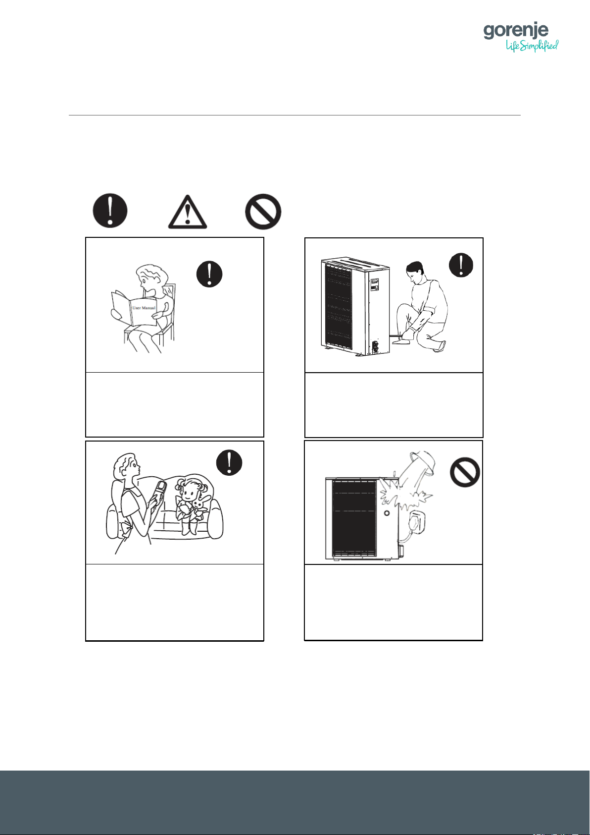
Installation, maintenance and
authorised person from Gorenje!
Pouring of water or any other
damage on the appliance!
Please read this instruction
This appliance is not intended for
person responsible for their safety!
1 BEFORE USE
1.1 SAFETY WARNINGS
Warning Caution Prohibition
manual carefully before using for
the first time!
uninstallation of the heat pump
can only be performed by an
use by people with reduced physical,
sensory or mental capabilities, or
lack of experience or knowledge,
unless they have supervision by a
fluid on or in the appliance is
strictly prohibited! Failure to
comply can lead to injuries and
1
Page 8
EN
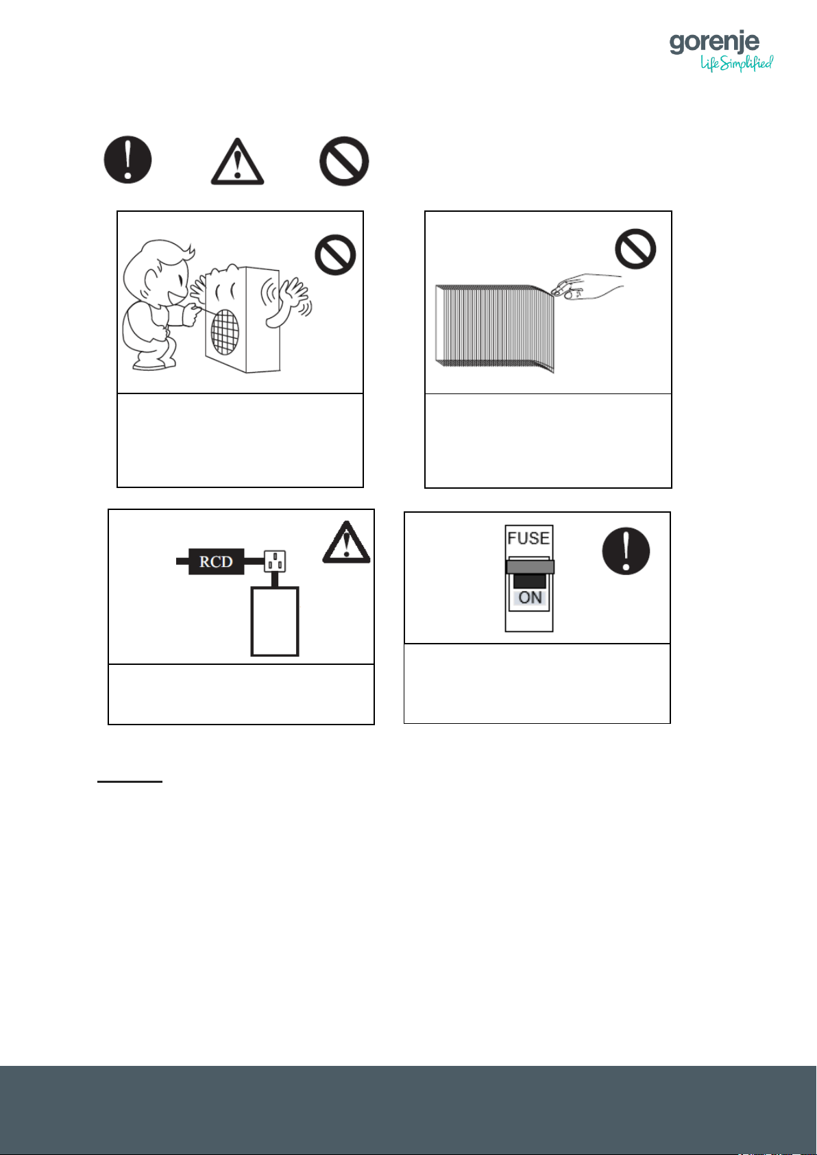
Do not touch the air outlet grid
Do not touch the leaves of the
It is advisable to install a switch on
the nominal current of 300 mA.
Main
Power
Suppl
COMPACT Units (Indoor and Outdoor Unit
automatic anti-freezing protection.
Warning Caution Prohibition
when the fan motor is operating!
vaporiser – their sharp surface
can cause cuts!
IndoorUnit
the differential current (RCD) with
with water system connections) must be
always with power supply to prevent freezing
of the water in the piping. Unit has an
Warning:
The Compact Type heat pumps have a hydraulic connection, which means that the medium
in the pipes (water or a mixture of water and concentrate antifreeze) can freeze if the heat
pump is not under voltage for a longer time. This may cause major damage to the heat pump
and on the system itself. For further information, please contact an authorized Installer or
Gorenje HVAC.
2
Page 9

EN
2 PRINCIPLE OF OPERATION OF THE HEAT PUMP
2.1 THE BASIC PRINCIPLE OF OPERATION OF A HEAT PUMP
A heat pump operates similarly as a refrigerator. In a refrigerator, liquids evaporate due to
received thermal energy from the surrounding air and this energy is emitted at a desired spot
during condensation (Carnot’s cycle). A heat pump works in the opposite direction: it accepts
thermal energy from the surrounding air and emits it in heated premises, using the natural
heat collector of the environment. Ground and surface water, earth’s warmth, solar energy
and ambient air can be used as energy sources. The system is composed of four units:
evaporator, compressor, condenser and damper. Heat energy is transferred via the coolant.
In the evaporator, the coolant receives heat energy and evaporates. In the compressor, the
vapour is compressed, which makes it heat up intensively. This hot vapour transmits thermal
energy from the condenser to the heating water and liquefies. In the damper, the coolant
expands (pressure reduces to the starting pressure, from there it proceeds to the evaporator
and the cycle repeats).
2.2 INVERTER HEAT PUMP
Inverter heat pumps use variable-speed compressors. Traditional heat pumps use fixed
power/rotation speed compressors. In inverter compressors, the compressor speed
constantly adapts to the heat losses of the room and the energy value of the source (air,
brine or water, depending on the system).
In traditional heat pumps, the power of the compressor is always the same. Compressor
starts with full power and when it achieves the desired values/temperatures, it shuts off and
waits until it restarts.
Inverter heat pumps work for a longer period of time, but with lower power (adjusting to the
premises), which means lower consumption of electric energy.
2.3 OPTIMISATION OF HEATING COSTS
2.3.1 Selection of heat pump
The first step towards the optimisation of heating costs is selecting the appropriate heat
pump. An over-dimensioned or under-dimensioned heat pump can cause higher heating
costs and shorten the lifespan of the appliance.
2.3.2 Heating curve
A correctly set heating curve is of key importance for the optimisation of heating costs. If a
room thermostat is used, the heating curve must be adjusted to the building as if it was not
existent. A too highly set heating curve can cause up to 30% higher heating costs!
2.3.3 Domestic water
Incorrect or too highly set desired temperature of domestic water can significantly increase
heating costs! In a traditional system with a 100-litre boiler, where domestic water is heated
by a heating element, the temperature necessary for meeting the needs of an average family
is much higher than in a system where domestic water is heated by means of a heat pump.
The difference lies in the quantity of the water in the water storage tank.
With heat pumps special water storage tanks are used that have a larger volume than
traditional boilers! For a heat pump system, daily consumption of 50 litres is assumed,
multiplied by the number of users of domestic water.
Example:
Family of four – 4 persons x 50 litres = 200 litres
3
Page 10

EN
2.3.4 In time of absence
Complete shutdown of a heat pump can lead to higher heating costs. We recommend using
the vacation mode, which lowers the temperature of heating and domestic water during your
absence, but does not allow the system to get completely cold, which would cause higher
heating costs upon system restart.
The next chapter describes how to make small steps to save a lot of energy.
3 HOW TO MAKE SMALL CHANGES TO
REDUCE HEATING COSTS
Every degree counts!
The use of heating energy depends on the temperature of the room. In a heated
apartment, every degree above 20 means up to 6 % higher energy use, i.e. higher
cost.
All windows and doors must be properly sealed!
Old windows and doors are usually not completely sealed, so draft takes warmth out
of the apartment. If crannies are visible, it’s crucial to take action as soon as possible.
Try to solve the problem by sticking sealing tapes on the contact surfaces or cut
notches for plastic sealing profiles / set the hardware or seal the internal casements in
classic (box) windows with separate casements.
Correct ventilation!
To feel good we need enough oxygen in the air, and we can get fresh air by means of
ventilation. If done correctly, we use up to 20% less energy for heating. Ventilate by
opening the window for a few minutes. Do this three times per day in each room. The
lower the temperature of ambient air, the shorter the ventilation should be.
Do not cover heating elements!
If heating elements are covered, air pockets occur that waste energy. It is
recommended to have curtains that only reach the level of radiators. Covering heating
elements can increase energy use by up to 10 %.
Set the appropriate temperature!
Is your heating regulation set to automatic or do your kids use it? If you want to
select the correct temperatures for your living environment, please consult with
experts who will tell you what temperature is the best for each living space. Already
two degrees – 22 degrees instead of 20 – can cause 12 % higher energy
consumption!
Check the possible causes for high energy consumption related to heating
If you think that you are using excessive amounts of energy, it is advisable to check
among the multiple causes for high heat losses:
– Old radiator valves (where thermostat valves are not built in);
– Poor or damaged heat insulation on internal installations after the measuring
point;
– Poorly maintained internal installations;
– Decrepit or improperly set temperature regulation automatics;
– Poor heat insulation of buildings (esp. older ones);
– Poorly sealed windows (especially without insulated glazing);
4
Page 11

EN
– Incorrect ventilation of premises (when ventilating rooms, make sure the
radiators are closed);
– The charged quantity of used heat for central heating of premises depends
mainly on the average outside temperature, so the consumption increases in
the start of the heating season, usually achieves the highest value in January,
and decreases at the end of the heating season;
– Longer accounting period than usual – may be caused by the inability to read
the status in the regular period, or if the ownership transfer documents arrived
too soon etc.;
– Incorrect operation of the measuring device;
– Status for the period of defect of the measuring device was determined based
on statistics.
Installation of heat cost allocators or calorimeters
If your apartment is in an old apartment building and you are paying for heat energy
consumption per square meter (flat rate), you can install heat cost allocators on
individual radiators in your apartment or, depending on the building, a calorimeter
before heating enters the apartment. In this case you can save heat energy
independently of your neighbour. However, in order to do this, more than one half of
apartment owners must be in favour of this with respect to the Rules on dividing and
billing heating costs in multiple-dwelling buildings. This way an individual apartment
building can save between 20 and 30 % of energy.
5
Page 12
EN
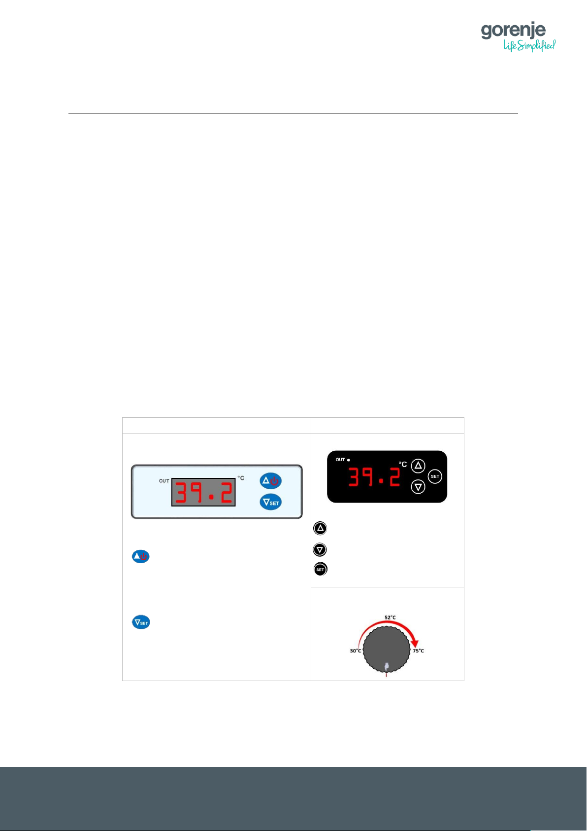
AS (Split) series
All In One AS series
Digital Thermostat
- hold = ON/OFF;
- push = Rising of the desired
temperature
- hold = stting the tempearure
- push = lowering of the desired
tempearture
Digital Thermostat
- rising of the set temp.
- lowering of the set temp.
- setting the desired temp.
Mechanical Thermostat
(DHW)
4 EMERGENCY OPERATION
Emergency operation is the operation of a heat pump with auxiliary heating sources such as
electric heaters, gas furnace, oil furnace or other heating source controlled by the heat pump.
Emergency operation is divided into Automatic and Manual operation.
Automatic Emergency Mode:
If the control detects that it cannot run the heat pumps as sources of heating due to possible
errors, additional heating sources for heating system and heating sanitary water will be
automatically switched on.
Note: the current Heating and DHW set temperature is automatically reduced by 7°C.
Manual emergency mode:
Activating this mode is a responsibility of the end user. This method is used in the event of a
failure of the master controller when it cannot control the system.
The heat pump has a manual switch to activate the manual emergency operation (the signal
light on the switch lights-up when it is activated). At this moment, all settings on the main
controller become invalid, because the control of the desired temperatures is exclusively
controlled by the additional thermostats that are installed on the device.
On the digital thermostat, set the desired heating temperature and the desired DHW
temperature on the mechanical thermostat.
Note: If the Digital Thermostat is manually switched OFF, so that on teh screan are three red
lines - - - , the Automatic emergency operation will be disabled.
6
Page 13
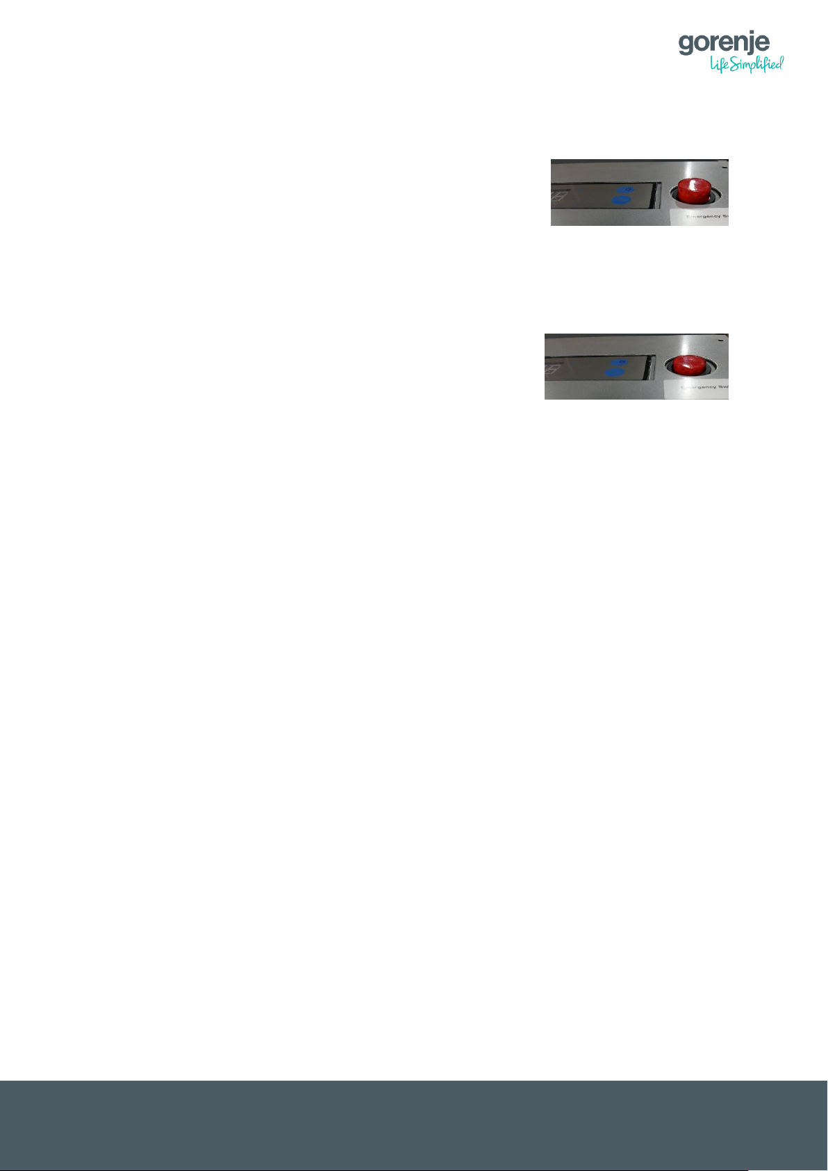
EN
Emergancy switch in OFF position – Heat pump works according to teh settings on the
main controller (tuch-screen controll panel)
Emergancy switch in ON position – Setting of teh main controller (tuch-screen controll
panel) will be disabled. All Circulating pumps (P0, P1, P2 an P3) start to work (always ON).
Temperature controll is only with Digital thermostat (controlling the set temperature of
electrical heaters). Diverting valve has to be set manualy to switch from Heating system to
DHW heating.
7
Page 14
EN
gorenje
gorenje
1 2 1
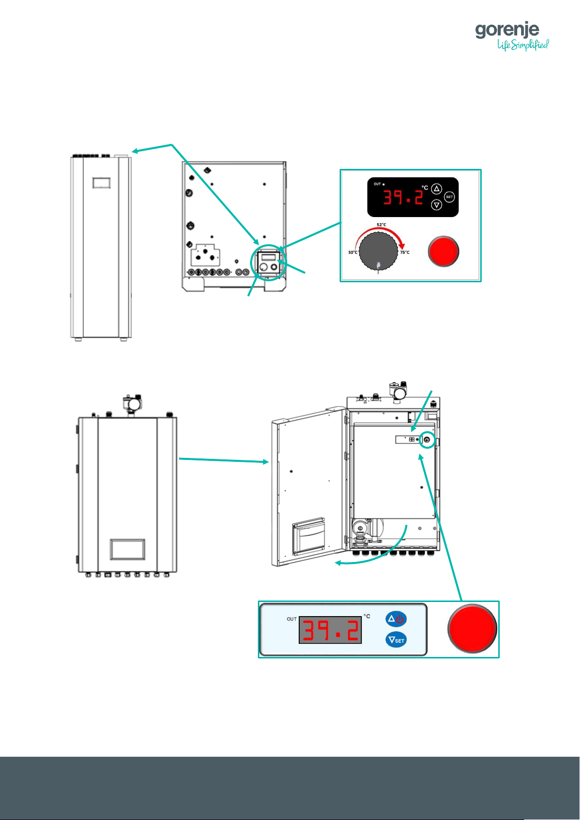
4.1 LOCATION OF THE EMERGENCY SWITCH
ALL-IN-ONE Inverter AS
AEROGOR Inverters AS
8
Page 15

EN
1. Digital thermostat controls the max flow temperature in case of Back-Up or Auto–
Emergency operation. In the Back-Up and Auto–Emergency operation, the Main
controller is still controlling the heating temperature.
Auto – Emergency operation
Example:
If the Unit turns ON the Back-Up heaters or Emergency operation and the setting on
the Digital thermostat is set to 30°C, the heaters will work only until 30°C and then
switch OFF regardless of the demand from the main controller. If, however the Digital
thermostat is set to 60°C, the Main controller will switch OFF the heaters according to
its needs.
Manual operation (manual emergency switch ON):
In manual operation all the circulating pumps are switched ON and the Electrical
heaters work according to the setting on the Digital thermostat, regardless of the
setting on the Main controller.
Example:
if the Manual emergency operation is ON and the temperature set on the Digital
thermostat is set to 50, the heating water will be heated to 50°C. The Circulating
pumps will run all the time.
2. Analog thermostat controls the max flow temperature in case of Back-Up or Auto –
Emergency operation for DHW. In Back-Up and Auto–Emergency operation, the Main
controller is still controlling the DHW temperature.
Auto – Emergency operation
Example:
If the Unit turns ON the Back-Up heaters or Emergency operation for DHW and the
setting on the thermostat is set to 40°C, the heaters will work only until 40°C and then
switch OFF regardless of the demand from the main controller. If however the
thermostat is set to 60°C, the Main controller will switch OFF the heaters according to
its needs (DHW set temperature).
9
Page 16

EN
e) Display of current
operation mode
f) Additional features,
operation modes
g) Warning or Error
h) Power ON/OFF
i) Settings
a) Operation mode
b) Heating or cooling
f) Communication
g) Heating of
domestic water
5 CONTROL UNIT
5.1 DESCRIPTION OF SYMBOLS ON THE CONTROL UNIT
a) Operation mode
This symbol shows the operation mode of the heat pump. Two modes are possible:
automatic or manual operation mode. With a short push on this symbol you can
select the operation mode. The recommended setting is automatic mode.
Automatic operation mode
The heat pump automatically switches between heating or cooling the house and
heating of domestic water!
Manual operation mode
In the manual Operation mode, the heat pump only prepares what you have selected
and ignores timers and the ambient temperature!
Only heating of premises (without domestic water, cooling, timers…)
Only cooling of premises (without domestic water, heating, timers…)
Only domestic water (without heating, cooling, timers…)
10
Page 17

EN
QuickHeat DHW (Fast heating of the DHW to the set value with the help of additional
heating sources. During QuickHeat, heating of premises is switched off. When the set
value of DHW water is achieved, the unit continues in normal operation).
If the “Pause” symbol is displayed, the heat pump is manually switched off!
b) Heating or cooling indicator
The symbol indicates that heating or cooling by ambient temperature or thermostat is
activated, or is activated due to manual operation mode!
Heating or cooling is activated or deactivated based on the ambient temperature!
Factory setting of enabled heating or cooling based on the ambient temperature:
Heating – 18 °C
Cooling – 25 °C
These values can be set as you wish.
Example:
Heating activation temperature is set to 18 °C. This means that when the average
ambient temperature exceeds 18 °C, the heat pump will stop heating. The sun
symbol will disappear from the display.
When the average ambient temperature drops below 18 °C, the sun symbol
reappears on the display and the heat pump will reinitiate heating of the premises,
unless an additional thermostat is used. In that case, the heat pump will require the
deactivation of the thermostat.
c) Activating the heating of domestic water
This symbol is visible on the display only when the heat pump is used for heating
domestic water.
The symbol is always visible on the display, unless the domestic hot water timer is
used.
If the domestic water timer is used, a different symbol appears in the domestic water
heating regime.
d) Communication
This symbol displays the communication status of the heat pump.
A light blue symbol indicates normal communication.
A grey symbol indicates loss of communication.
In this case, an error symbol is displayed as well. Please notify an authorized service
person immediately!
e) Display of the current Operation mode
The heat pump displays the current Operation mode.
Heating
Cooling
Heating of domestic water
QuickHeat
11
Page 18

EN
f) Additional features, modes of operation
This symbol appears when the reduced setpoint for heating is on (see chapter
Reduced Setpoint for Heating).
This symbol appears when the “Floor Curing” feature is on.
This symbol appears when the heat pump is in the “Anti-Legionella” mode.
This symbol appears when “Electrical Utility Lock” is on.
This symbol appears when the heat pump is in the “Defrosting” mode.
This symbol appears when the timer for the preparation of domestic water is on
This symbol appears when the timer for heating / cooling is active.
This symbol appears when Heating ECO operation is active.
g) Warning or Error
An exclamation mark appears on the screen, cautioning about an error.
Minor error; considered as a warning. Heat pump operates normally, but an
authorized service person should be informed immediately!
Major error; to ensure safety of the system and the heat pump, the pump is shut
off. If the “Emergency Operation” feature is on, the heat pump will continue
working, but only with backup heating sources!
Please inform an authorized service person immediately!
h) Power on/off
Heat pump power on/off.
Heat pump on means that the system is active for heating, cooling and preparation
of hot domestic water! The symbol is blue!
Heat pump off means that the system is switched off except for the Anti-freezing
protection which is on! The symbol is grey!
Anti-freezing protection protects the system from freezing. The heat pump
automatically checks the water temperature. If it drops below a certain value,
potentially causing system damage due to system water freezing, it turns on to
increase the water temperature to a safe temperature level.
i) Settings
This button can be used to access menus.
12
Page 19

EN
j) Current and
desired
temperature
of domestic
water
k) Current and
desired
temperature
of heating /
cooling
l) Ambient
temperature
m) Room
temperature
n) Temperature
of domestic
water
5.2 DESCRIPTION OF TEMPERATURES ON THE CONTROL UNIT
j) Current and desired temperature of domestic water
Two temperatures are displayed:
Above – Current temperature
Below – Desired temperature
k) Current and desired temperature of heating/cooling
Two temperatures are displayed:
Above – Current temperature
Below – Desired temperature (calculated from the heating curve or desired
temperature).
l) Ambient temperature
The current ambient temperature is displayed.
m) Room temperature
The current room temperature is displayed.
The temperature sensor does not control the operation of the heat pump! It can be
used for the “Room temp. Effect on the Heating Curve” feature, which automatically
reduces or increases the heating curve by a few percent.
n) Temperature of domestic water
The current temperature of domestic water is displayed.
13
Page 20

EN
6 RISING / LOWERING THE ROOM
TEMPERATURE
There are two posibilitis, to contrll the room temperature:
1. Exclusively accordint to Ambient temperature (Outdoor temperature)
2. Combination of Ambient temperature and Room temperature
6.1 EXCLUSIVELY ACCORDING TO AMBIENT TEPPERATURE
By pressing in the middle of the house an additional window appears. First window is for
setting the Paralel move of the Heating curve for the First Heating Circuit. Changing this
setting will change the Room temperature. It can be set from -3 to 3. The number 0 is the
default setting of the Heating curve. By rising the setting to +3, the room temperature will
increase for 1-2°C, depending on the heating system (Radiators, floor heating system, Fan-
Coils). Both heating circuits can be set separately.
- Setting the parallel move for the first heating circuit – see chapter 7.1.1
- Setting the parallel move for the second heating circuit – see chapter 7.1.2
6.2 COMBINATION OF AMBIENT TEMPERATURE AND ROOM TEMPERATURE
If TR room temperature sensor is used, the function ˝Room temp. effect on Heating Curve˝
can be enabled. Heat pump will not start or stop according to the Romm temperature it will
automaticly correct the heating curve, to come close as possible to the Ideal room
temperature setting.
For example: If the room temperature is too high, the Heating curve will automaticly
decrease. If the room temperature is to low, the heating curve will automaticly increase.
If the room temperature is still far from the Ideal Room temperature setting, the heating curve
itselfe must be increased or decreased.
Ideal room temperature setting can be changed in menu ˝Heating/Cooling Citcuit 1˝, page 4
– ˝Ideal Room temp. in Heating˝
Page 4
Note:
This setting influences both heating circuits.
14
Page 21

EN
Parallel move of the
set to - 2)
Heating Curve –
Ambient temperature (°C)
Flow temperature of the hating system (°C)
By pressing on the Room
temperature display, an
additional window appears.
With buttons ˝+˝ or ˝– ˝ the
heating curve can be changed
for the desired value. Confirm
the setting with button ˝OK˝.
7 QUICK SETTINGS
What is a parallel move of the heating curve?
At start-up, the heating curve is adjusted according to the heating system (Floor heating
system, Radiators, Fan coils) and desired room temperature.
The setting can be changed from the Main screen, but only the complete move of the heating
curve and not each reference point separately. The heating curve can be raised or lowered
for 3 °C (-3 to +3).
By raising the heating curve for 2-3 °C would mean an increase of the room temperature for
approx. 1 °C.
The graph below shows a parallel move of the heating curve – lowering of the heating curve
for 2°C
normal setting
(Parallel move set to
heating curve for -
2°C (Parallel move
7.1.1 SETTING THE PARALLEL MOVE OF THE HEATING CURVE – HEATING
CIRCUIT 1
15
Page 22

EN
By pressing on the room temperature
display, an additional window
appears.
OK
Cancel
System 1 Heating Curve Parallel Move 2: 0°C
OK
Cancel
Desired temperature: 47°C
7.1.2 SETTING THE PARALLEL MOVE OF THE HEATING CURVE – HEATING
CURVE 2
PARALLEL MOVE OF THE HEATING CURVE 2 IS AVAILABLE ONLY WHEN USING TWO
HEATING CIRCUITS!
First the window for parallel move of the first heating circuit appears. To access the setting of
the parallel move for the second heating circuit press . Second page appears with the
setting for the second heating circuit.
With buttons ˝+˝ or ˝– ˝ the heating curve can be changed for the desired value. Confirm the
setting with button ˝OK˝.
7.2 SETTING THE DHW TEMPERATURE
By pressing on the DHW temperature, an additional window appears.
With buttons ˝+˝ or ˝– ˝ the DHW set temperature can be changed for the desired value.
Confirm the setting with button ˝OK˝.
Domestic hot water settings depend on the user’s habits.
The recommended setting for domestic hot water is between 47 °C and 50 °C.
Traditional systems (boilers) use smaller domestic water storage tanks, so the temperature
must be significantly higher than in a heat pump system, which causes higher costs of
domestic hot water preparation!
In principle, a heat pump system is planned to store 50 litres of water per person. This
means that a family of four needs a minimum of 200 litres of hot water per day.
Note:
Mixing of cold and warm water in a mixing tap differs according to the systems of how
domestic water is heated.
If the traditional domestic water heating system is used, less hot water is mixed with cold
than in a heat pump system.
16
Page 23

EN
In a heat pump system, a larger quantity of hot water is mixed with cold water, as the volume
is larger and the temperature is lower (contributing to lower costs) than in the traditional
system, where the water volume is 2-3 times smaller.
7.3 SETTING THE FIXED TEMPERATURE OF HEATING CIRCUIT
This quick setting is available only when one or both heating circuits are used without heating
curves.
7.3.1 SETTING THE FIXED TEMPERATURE FOR THE FIRST HEATING CIRCUIT
By pressing on the temperature below the line, beside the sun symbol, an additional window
will appear.
With buttons ˝+˝ or ˝– ˝ the fixed temperature for the first heating circuit can be changed for
the desired value. Confirm the setting with button ˝OK˝.
7.3.2 SETTING THE FIXED TEMPERATURE FOR THE SECOND HEATING
CIRCUIT
By pressing on the temperature below the line, beside the sun symbol, an additional window
will appear. Press the arrow in the down right corner to access the setting for the second
heating circuit.
With buttons ˝+˝ or ˝– ˝ the fixed temperature for the second heating circuit can be changed
for the desired value. Confirm the setting with button ˝OK˝.
17
Page 24

EN
User menu Service menu
8 USER INTERFACE
8.1 ARRANGMENT OF MENUS
The control unit has two levels of menus. The first page of the menus is intended for the end
user, and the second page is for the authorized service person or for install settings with
some excluded exceptions.
8.2 MENU ACCESS
By pressing you can access the menus with settings for the end user, as well as the
service settings (see image below)!
Service settings are protected by a service code. The end user is not allowed access to
these settings. The user can view the settings but is not allowed to change them!
18
Page 25

EN
9 SETTINGS
Heating
The heat pump enables two heating circuits, meaning that it can control two different
temperature modes. Heating/cooling circuit 1 and Heating/cooling circuit 2
When only one heating circuit is in use, the heating settings are defined in the menu
“Heating/cooling circuit 1“!
9.1 HEATING/COOLING CIRCUIT 1
19
Page 26

EN
9.1.1 Heating/Cooling Stops Based on Water ∆T
Temperature setting that allows overheating of the heating system for the set value.
The recommended setting is 2 °C! This enables efficient operation of the Inverter technology
and brings the highest savings.
Please note, that we allow the Heat Pump to overheat the system, to maintain a low working
speed and to avoid a frequent stopping and starting of the compressor.
9.1.2 Heating/Cooling Restarts Based on ∆T
The compressor restarts based on the set values of heating/cooling circuits.
The recommended value is 2 °C. This enables efficient operation of the Inverter technology
and brings the highest savings.
9.1.3 ∆T Compressor Speed Reduction
This setting tells the system when will the compressor start lowering its working speed. The
recommended value is 2 °C. This enables efficient operation of the Inverter technology and
brings the highest savings.
For example:
If the set/calculated temperature is 30°C and the ˝∆T COMPRESSOR SPEED REDUCTION˝
is set to 2°C, the compressor will work at its max working speed (check chapter ˝Max
Compressor Working Speed˝) till it reaches 28°C. At a 28,1°C and above the compressor
speed will start to decrease towards the lowest working speed of the compressor.
9.1.4 Set temp. For cooling
Setting the desired cooling water temperature of the first cooling circuit is set (the second
circuit is set in the menu “Heating/Cooling Circuit 2”).
9.1.5 Heating Curve
The heating curve mode is based on the condition that the lower the ambient temperature is,
the higher the water temperature for the heating of facility is. This heating curve mode can
help the heat pump to achieve a higher COP (efficiency rate) and increase the feeling of
comfort in the house.
As the level of home insulation and people’s feeling of cold can differ, the factory set curve
may not be appropriate for everybody. The heating curve may be set according to customers
needs.
The basic setting of the heating curve is made upon the first start-up of the heat pump. The
start-up must be performed by an authorized service person!
The basic setting is always adjusted according to the system that is installed (underfloor
heating, radiators, convectors (Fan Coil)). To determine the basic heating curve, we also
need to take into account the insulation of the facility!
The heat pump enables two heating circuits with different heating curves.
20
Page 27

EN
Tsh – Space heating temp.; T(Ta) – Ambient temp.
Ta1
Ta2 Ta3 Ta4
Ta5
Tsh1
Tsh2
Tsh3
Tsh4
Tsh5
NOTE:
It is recommended to reset only the space heating water temperatures (figure above on
the right). Resetting ambient temperatures for the heating curve affects both heating
circuits.
EXAMPLE
Example:
The customer wants the room temperature to be 21 °C, but the heat pump heats the rooms to 22 °C. In
this case the heating curve must be lowered. On page 3, all temperatures need to be lowered by 2-3 °C,
which means that the room temperature will be lower by 1 °C. If the room temperature is lower than the
desired temperature, the temperature values must be increased.
9.1.5.1 SETTING THE HEATING CURVE FOR THE FIRST HEATING CIRCUIT
Heating curve is set on page 3 of the “Heating/Cooling Circuit 1” menu!
PAGE 3
21
Page 28

EN
9.1.6 Room temp. effect on Heating Curve
When the temperature sensor ˝TR˝ is mounted in the living area, this function can make
small corrections of the heating curve, depending on the set “Ideal Room Temp. in Heating”.
Note:
This feature does not mean temperature control by room temperature, but only a correction
of the heating curve!
If this feature is on and the temperature in the room (where the TR room temperature sensor
is located) still exceeds the set ideal value, the heating curve settings should be reset!
9.1.7 Ideal Room temp. in Heating
Relates to parameter (6.3.1.6).
The setting is active only when the feature “Room Temp. Effect on Heating Curve” is
enabled.
9.1.8 Ideal Room temp. in Cooling
Relates to parameter (6.3.1.6).
The setting is active only when the feature “Room Temp. Effect on Heating Curve” is on
9.1.9 Set Temperature for heating – without heating curve
Set temperature for the heating water system – without heating curve.
When the heating curve is disabled, the heat pump operates with fixed system heating water
temperature.
Weather-related control of the heating circuit is disabled, which can lead to higher heating
costs!
NOTE:
The parameters in grey are protected by a service code!
9.1.10 Low Temperature Limit
Service setting.
9.1.11 High Temperature Limit
Service setting.
9.1.12 Mixing Valve
Service setting.
22
Page 29

EN
9.2 HEATING/COOLING CIRCUIT 2
9.2.1 Heating/cooling Circuit 2
A check in a box means that the heating/cooling circuit 2 is on.
9.2.2 Set temp. for Cooling
Setting the desired space cooling water temperature in Cooling Circuit 2.
The desired temperature of Cooling Circuit 2 is set.
9.2.3 Set Temp. For Heating – without heating curve
Set temperature of space heating water– without heating curve.
When the heating curve is off, the heat pump operates with fixed space heating water
temperature.
Weather-related control of the heating circuit is off, which can lead to higher heating costs!
9.2.4 Mixing Valve
Service setting.
NOTE:
If the second heating circuit is active and the room thermostat is not used, a wire must be
placed between TH and COM. If a wire is not placed between TH and COM, the heat pump
will heat the buffer tank according to the lower temperature demand.
23
Page 30

EN
Tsh – Space heating temp.; T(Ta) – Ambient temp.
Ta1
Ta2 Ta3
Ta4
Ta5
Tsh1
Tsh2
Tsh3
Tsh4
Tsh5
9.2.5 Heating Curve
The heating curve mode is based on the condition that the lower the ambient temperature is,
the higher the water temperature for the heating of facility is. This heating curve mode can
help the heat pump to achieve a higher COP (efficiency rate) and increase the feeling of
comfort in the house.
As the level of home insulation and people’s feeling of cold can differ, the factory set curve
may not be appropriate for everybody. The heating curve may be set according to customers
needs.
The basic setting of the heating curve is made upon the first start-up of the heat pump. The
start-up must be performed by an authorized service person!
The basic setting is always adjusted according to the system that is installed (underfloor
heating, radiators, convectors (Fan Coil)). To determine the basic heating curve, we also
need to take into account the insulation of the facility!
The heat pump enables two heating circuits with different heating curves.
NOTE:
It is recommended to reset only the space heating water temperatures (figure above on the
right). Resetting ambient temperatures for the heating curve affects both heating circuits.
24
Page 31

EN
EXAMPLE
9.2.5.1 SETTING THE HEATING CURVE FOR THE SECOND HEATING CIRCUIT
Heating curve is set on page 2 of the “Heating/Cooling Circuit 2” menu!
Example:
The customer wants the room temperature to be 21 °C, but the heat pump heats the rooms to 22 °C.
In this case the heating curve must be lowered. On page 3, all temperatures need to be lowered by 2-
3 °C, which means that the room temperature will be lower by 1 °C. If the room temperature is lower
than the desired temperature, the temperature values must be increased.
9.3 DHW SETTINGS
25
Page 32

EN
9.3.1 Setpoint DHW
Setting of the desired temperature for domestic water.
9.3.2 DHW Restart ∆T Setting
Domestic hot water restart setting.
Example:
Desired temperature of domestic water is 47 °C, and the domestic hot water restart ∆T
setting is 5 °C. (47–5=42)
This means that the heat pump will restart the heating of domestic water when the
temperature drops below 42 °C!
Recommended domestic hot water restart ∆T setting is 5 °C!
9.3.3 Shifting Priority
The heat pump has absolute priority for the preparation of domestic hot water. With this
feature, the priority adjusts to the heat losses when the ambient temperature reaches a
certain point.
This feature is used in new buildings that still lack insulation and that will be without
insulation for at least one heating season.
9.3.3.1 Enabling or Disabling the Shifting Priority function:
Disabled (default setting) – the Heat Pump will switch to Heating mode only when the
desired DHW temperature is reached.
Enabled – the Heat Pump will decide based on the temperatures of the heating system if it
should switch to heating although the DHW set temperature is not reached yet.
For example:
Set temperature for DHW is 47°C and the Heat Pump is currently working in DHW mode.
The actual DHW temperature is 44°C, meaning it still has to heat up the DHW for another
3°C, before it can switch to heating mode (heating the House). In that moment, the Unit sees
that the temperature of the Heating water for the heating system is dropping for a certain
value, meaning it is a high risk of undercooling the house. It switches to Heating mode to
provide heat to the house. When the temperature is in safe level, or the max set time for
heating is exceeded, the Heat Pump switches back to DHW mode to heat up the DHW to the
desired value, before it switches back to Heating mode.
9.3.4 Shifting Priority Starting Temperature
Only valid if Shifting Priority enabled!
Setting the Ambient temperature to activate the Shifting Priority Function.
If the Shifting Priority Function is enabled it will not be active before the Ambient temperature
falls below a certain value (Shifting Priority Starting temperature).
9.3.5 Sanitary Water Min. Working Hours
Only valid if Shifting Priority enabled!
This setting is set in Minutes!
The Heat Pump will try to heat up the DHW for a minimum time before it switches to Heating,
even if all other conditions for Shifting Priority are met.
9.3.6 Heating Max. Working Hours
Only valid if Shifting Priority enabled!
This setting is set in Minutes!
26
Page 33

EN
When the Heat Pump switches to Heating mode in Shifting priority mode, it will allow the unit
to stay in Heating mode only for a certain time, before it switches back to heat up the DHW.
9.3.7 Allowable temp. Drift in Heating
Only valid if Shifting Priority enabled!
Setting for the max. Temperature drift in heating system during DHW heating mode. Only
when this value is exceeded, the Unit will switch to heating.
9.3.8 DHW Backup Heater for Shifting Priority
Only valid if Shifting Priority enabled!
Disabled – Backup heater will work only according to the normal back-up stings.
Enabled – Backup Heater will help to faster heat up the DHW.
9.3.9 DHW ECO Operation
Service setting.
9.3.10 Ambient Temp. to Start DHW ECO Operation
Service setting.
9.4 DHW STORAGE
9.4.1 Sanitary Hot Water Storage Function
Feature on/off.
A check in the box means that the feature is on.
This feature enables water preparation at a certain time and day. It is set for each day of the
week individually.
9.4.2 Sanitary Hot Water Storage Timer
Setting domestic water heater timer!
27
Page 34

EN
If the fields are green, domestic water heating is on.
If the fields are grey, it means the heat pump is not heating domestic water.
9.4.3 Reheating Function
Feature on/off.
A check in the box means that the feature is on.
The feature enables the setting of a second temperature mode for domestic water heating.
This means that it enables two different temperatures of domestic water at various times in
an individual day of the week.
Setting of a second temperature of domestic hot water corresponds to the parameter
“Reheating Set Temp.”.
9.4.4 Reheating Function Timer
Setting the second timer for the heating of domestic hot water!
If the fields are green, domestic water heating is on.
If the fields are grey, it means the heat pump is not heating domestic water.
9.4.5 Reheating Set Temp.
Setting the desired temperature for the second mode of heating of domestic water.
This temperature will be the default temperature for domestic water heating in the “double
mode”.
The temperature can be lower or higher than the primary setting of the desired domestic hot
water temp.!
Note:
If timers overlap, the heat pump will take into account the higher level of desired domestic
water temperature!
9.4.6 Reheating Restart ∆T Setting
For the second temperature mode for heating domestic water, this parameter is used to set
the DHW restart. The recommended setting is 5 °C.
Example:
Desired domestic hot water temperature is 45 °C, and the DHW restart setting is 5 °C. (45–
5=40).
Heat pump will start reheating domestic water once it drops below 40 °C.
28
Page 35

EN
9.5 REDUCED SETPOINT
9.5.1 Reduced Setpoint
Feature on/off.
A check in the box means that the feature is on.
The feature lowers water temperature by the set value for both heating circuits in the set
time. The main purpose is to lower room temperature at night.
9.5.2 Temp. Drop/Rise
The space heating water temperature drop/rise is set for both heating circuits.
9.5.3 Timer for Reduced Setpoint Function
Timer for feature activation is set!
If the fields are green, domestic water heating is on.
If the fields are grey, it means the heat pump is not
heating domestic water.
9.5.4 Quiet Operation
Feature on/off.
A check in the box means that the feature is on.
Quiet operation means that the heat pump tries to operate with the lowest possible rpm of
compressor and fans, so that noise is reduced in the night time.
The maximum deviation from the desired space heating water temperature is set.
29
Page 36

EN
9.5.5 Allowable Temp. Drifting
The maximum allowable space heating water temperature drifting is set for both circuits
when the “Quiet operation” feature is on.
9.5.6 Timer for Quiet Operation
Timer for the Quiet Operation Feature!
If the fields are green, the feature is on.
If the fields are grey, it means the feature is off – normal
operation!
Note:
If the timers “Reduced Setpoint” and “Quiet Operation” overlap, the heat pump will operate in
the quiet mode with an additional temperature drop, as set in the “Temp. Drop/Rise”.
9.6 ANTI – LEGIONELLA
9.6.1 Anti – Legionella Program
Feature on/off.
A check in the box means that the feature is on.
For the Anti-legionella feature to operate, an electric heater must be installed in the DHW
tank!
What is legionella?
Legionellae are bacteria that can appear in ground and surface fresh water. They can also
be found in pipelines, heating systems (apartments, hospitals, and hotels), cisterns, boilers,
whirlpools, pools with heated water, cooling water, cooling towers, air humidifiers, diffusers
etc.
The basic condition for legionella to develop is increased water temperature. The largest
populations of bacteria can be found in the temperature zone between 38 and 42 °C, which
is the temperature most often used when taking a shower. With such conditions, a single
legionella can breed to several hundred thousand in merely three days. It has also been
30
Page 37

EN
found in pipelines with low flow rates or where water was stagnant in pipes for a longer
period of time (inactive parts of buildings, basement etc.). Domestic hot water storage tanks
with layered temperature distribution are also possible sources of contamination. Legionella
can also be found in cool water, but its growth is hindered, which makes it almost nonexistent or at least very rare in subterranean waters and cold potable waters. Water from
pipelines is hygienically safe. Legionella colonies start thriving in hot water systems, where
water can be stagnant for weeks in a hot water tank, offering an additional breeding ground
for legionellae and other bacteria.
To prevent legionella, water must be heated. In fact, it must be heated to over 60° C, in order
to destroy bacteria. It takes 3.5 minutes for the bacteria to be destroyed. This means that
water must be heated to a minimum of 60 °C for at least 3.5 minutes.
9.6.2 Day and Time
The day and time for the feature to be switched on is set here.
The recommended setting is Monday at 2:00 AM.
9.6.3 Setpoint
The desired temperature (setpoint) of the Anti-legionella feature is set here.
9.6.4 Duration
Here you can determine how long the heat pump should maintain the desired temperature in
the Anti-legionella programme!
9.6.5 Finish Time
If the heat pump cannot heat the domestic water in the set time, the programme is
terminated and an error message appears on the display.
31
Page 38

EN
9.7 VACATION MODE
9.7.1 Vacation Mode
A check in the box means that the feature is on.
This feature can be used for the time when you are absent and there is no need for heating
or hot water. The date of departure (start date) and date of arrival (finish date) is set and the
desired heating and water temperature drop for the duration of your vacation.
9.7.2 Sanitary Hot Water Temp. Drop during Vacation Mode
Setting domestic hot water temperature drop during the vacation mode.
9.7.3 Heating Water Temp. Drop during Vacation Mode
Setting heating water temperature (heating) drop during the vacation mode
9.7.4 Vacation Start Date
Setting the start date of vacation.
9.7.5 Vacation Finish Date
Setting the finish date of vacation.
32
Page 39

EN
9.8 USER MANAGEMENT
9.8.1 Permission Level
Enter the Service Password to enter the Service / Installer level.
9.8.2 Heating/Cooling ON/OFF timer
Disabled (default setting) – Normal operation
Enabled – The Heat Pump Will Heat and Cool only according to the setting of a Timer. In the
other time, it will be only in Antifreeze protection mode.
Please note, that this has no influence on the DHW mode.
SETTING THE TIMER:
Green fields mean that heating/cooling depending on the
ambient temperature is on.
Gray fields mean that heating/cooling depending on the
ambient temperature is blocked.
9.8.3 Language
Setting the language of the interface.
9.8.4 Set Date and Time
Setting the time and date.
9.8.5 Distribution System Setting
Service setting.
9.8.6 Save Current Settings
Service setting.
9.8.7 Load Saved Settings
Reset all settings to “Install Settings”.
33
Page 40

EN
All settings are reset to the settings stored during the last intervention by an authorized
service person.
9.8.8 Switch to Factory Settings
Service setting.
9.9 MODE SETTINGS
9.9.1 Ambient Temp. To Start Heating
Setting the Ambient temperature to start Heating mode.
Default setting is 18°C.
Example:
The set temperature to start heating is 18 °C.
The heat pump will heat the facility depending on the set values (heating curve or constant
space heating water temperature, depending on the settings), if the ambient temperature
drops below 18 °C.
When the ambient temperature rises above 18 °C, the heat pump will automatically stop
heating the facility.
It will resume heating when the ambient temperature drops below 18 °C.
Note:
To prevent too frequent switches between operation and non-operation, the control unit
monitors the current temperature and temperature within a certain period and decides based
on this whether heating should be activated or blocked.
34
Page 41

EN
9.9.2 Ambient Temp. To Start Cooling
Setting the activation/start of cooling at a certain ambient temperature.
The factory setting is 25 °C.
Example:
The set temperature to start cooling is 25 °C.
The heat pump will cool the facility depending on the set values if the ambient temperature
rises above 25 °C.
When the ambient temperature drops below 25 °C, the heat pump will automatically stop
cooling the facility.
It will resume cooling when the ambient temperature rises above 25 °C.
Note:
To prevent too frequent switches between operation and non-operation, the control unit
monitors the current temperature and temperature within a certain period and decides based
on this whether heating should be activated or blocked.
9.10 BACKUP HEATING
In the “Backup Heating” menu you can set the backup heating sources. By factory default,
these heating sources are two-stage electric heaters that can be replaced with a different
heating source (pellet burning furnace, oil burning furnace etc.). In this case, the heat pump
regulates the switching on/off of the furnace.
Note:
Resetting the settings in the “Backup Heating” menu is only recommended upon consulting
with an authorised service person!
35
Page 42

EN
Service setting
Service setting
Service setting
9.11 WATER PUMP SETTINGS
9.12 FLOOR CURING
9.13 ELECTRICAL UTILITY LOCK
36
Page 43

EN
Service setting
9.14 OTHER OPTIONS
9.15 UNIT REAL-TIME DATA
Unit real-time data pages can be used for diagnostics of operation of the heat pump. On
these pages, you can see everything that is happening in the heat pump in that moment.
You can see different values for which include:
Software Version
Database Version
Tuo, Tui, Tup, TW, TC temperature values
Water Flow Rate
Compressor Speed
EEV operation
Ambient Temperature (Actual, Average Temp. in 1 h, Average Temp. in 24 h)
High pressure
Low pressure
Td, Ts, Tp temperature values
…
37
Page 44

EN
Main display Error Code Menu
By pressing on the Error code number, a more detailed information for this Error code will appear on the top.
Display of
Active Errors
Error History
Display
10 ERROR CODES
If some faults happen and some errors appear, it is not always because of the heat pump
itself. The most errors happen due to the hydraulics system and especially in the first heating
season (water pressure falls, air in the system, dirt in the piping…).
10.1 ERROR CODES SHOWN ON THE DISPLAY
The error codes will be shown on the Main display and in the Error Code Menu.
10.2 ERROR CODE MENU
10.2.1 ACCESSING THE ERROR CODE MENU
10.2.2 INFORMATIONS IN THE ERROR CODE MENU
38
Page 45

EN
TC
Heating / Cooling (direct circuit or Buffer
Tank)
TW
DHW Temperature
TV1
Mixing Circuit 1
TV2
Mixing Circuit 2
TR
Room Temperature
Line
status 1
Communication – Touch Screen controller to
the Indoor PCB 90 – 100 % = normal
communication
Line
status 2
Communication – Touch Screen controller to
the Outdoor PCB 90 – 100 % = normal
communication
Pump
speed
100 = Pump P0 Activated
0 = Pump P0 Deactivated
TC
By selecting an Error code and pressing More info button, unit displays additional info
regarding the status of the heat pump at the time when the error happened.
10.2.3 INFO PAGE
By pressing the and then takes you to the info page. First thing that is displayed is the
hydraulic scheme with temperature readings from all the sensors. This screen is the same for
all Aerogor Inverter heat pumps.
39
Page 46

EN
Ta
Ambient Temperature Sensor
Tui
Condenser Inlet Temperature Sensor
Tuo
Condenser Outlet Temperature Sensor
Tup
Liquid Refrigerant Temperature Sensor
Ts
Suction Temperature (Compressor) Sensor
Td
Discharge Temperature (Compressor)
Sensor – Hot Gas Temperature
Tp
Evaporation Temperature Sensor
Ps
Low pressure – Suction pressure
Pd
High pressure – Discharge pressure
Fan 1,2
Fan speed for Fan 1 and Fan 2
Compressor speed (Hz)
Compressor current (A)
Pe – Pressure EVI
Te – Temperature EVI
EEV
Opening
EVI
Opening
By pressing the right arrow button , the interface shows the heat pump system scheme.
This scheme is different for ECO and POWER EVI inverters.
Aerogor ECO Inverter
Aerogor POWER EVI Inverter
40
Page 47

EN
Category
Description
Symbol
Notification
Is only to inform the customer that some special function has turned on,
which is still normal operation of the heat Pump.
*
Code
Name
What to do…
If nothing
helps…
P01
Main line current
protection
Clean the cleaning element (filter), check water pressure, water set
temperature for DHW or heating system is set to high, hand valve is
partly or totally closed, problem with power supply to the Heat Pump.
Call customer
service.
P02
Compressor phase
current protection
Clean the cleaning element (filter), check water pressure, water set
temperature for DHW or heating system is set to high, hand valve is
partly or totally closed.
Call customer
service.
P03
IPM module protection
/
Call customer
service.
P04
*
Compressor oil return
protection
Normal operation! This is not an ERROR!
No attention
needed
P05
Compressor shut down
due to high/low
pressure switch open
caused by abnormal
high/low pressure
Clean the cleaning element (filter), check water pressure, water set
temperature for DHW or heating system is set to high, hand valve is
partly or totally closed.
Call customer
service.
P06
Compressor speed
down due to abnormal
high pressure detected
by condensing
pressure sensor
Clean the cleaning element (filter), check water pressure, water set
temperature for DHW or heating system is set to high, hand valve is
partly or totally closed.
Call customer
service.
P07
*
Compressor preheating
Normal operation! This is not an ERROR! Preheating of the
compressor at start up or repowering at low ambient temperatures.
No attention
needed
P08
Compressor discharge
temp. too high
protection
Clean the cleaning element (filter), check water pressure, water set
temperature for DHW or heating system is set to high, hand valve is
partly or totally closed.
Call customer
service.
P09
Outdoor evaporator coil
temp. sensor protection
Clear the Outdoor unit from dirt.
Call customer
service.
P10
AC over high/low
voltage protection
Problem with power supply to the Heat Pump.
Call customer
service.
P11
Compressor shut down
due to too high/low
ambient temperature
Normal protection due to, too high or too low outdoor temperature.
When the ambient temperature gets back in the safe zone for the Heat
Pump to work, it will start again automatically.
No attention
needed
P12
*
Compressor speed
limited due to too
high/low ambient
temperature
Compressor speed down
Normal operation
- no error
P14
Compressor speed
limited due to low
condensing pressure
Call customer service.
/
F01
Outdoor ambient temp.
sensor failure
Call customer service.
/
F02
Outdoor evaporator coil
temp. sensor failure
Call customer service.
/
F03
Compressor discharge
temp. sensor failure
Call customer service.
/
F04
Outdoor Suction temp.
sensor failure
Call customer service.
/
F05
Evaporating pressure
sensor failure
Call customer service.
/
F06
Condensing pressure
sensor failure
Call customer service.
/
10.3 ERROR CODE LIST
In this Code list are Notifications, Protections and Errors!
41
Page 48

EN
F07
High/low pressure
switch failure
Call customer service.
/
F09
DC fan failure (one)
Heat Pump will continue to work, but with lower heating capacity.
Call customer
service.
F10
DC fan failure (two)
Heat Pump will continue to work, but with lower heating capacity.
Call customer
service.
F11
System evaporating
pressure too low
Clear the Outdoor unit from dirt.
Call customer
service.
F12
System condensing
pressure too high
Clean the cleaning element (filter), check water pressure, water set
temperature for DHW or heating system is set to high, hand valve is
partly or totally closed.
/
E01
Communication
between operation
panel and indoor PCB
or outdoor PCB failure
Call customer service.
/
E02
Outdoor power PCB
and driver PCB
communication failure
Call customer service.
/
E03
Compressor phase
current failure
(open/short circuit)
Call customer service.
/
E04
Compressor phase
current overload (over
current)
Call customer service.
/
E05
Compressor driver
failure
Call customer service.
/
E06
Module VDC over
high/low voltage failure
Call customer service.
/
E07
AC current failure
Call customer service.
/
E08
EEPROM failure
Call customer service.
/
E10
Communication error
Call customer service.
/
E11
Clock error
Call customer service.
/
E12
Ext. Memmory error
Call customer service.
/
E13
High pressure
protection
Possible causes: Dirty filter, low water pressure, voltage fluctuation,
set temperature to high, closed or half-closed valve on the hydraulic
system.
Call customer
service.
E14
Low pressure
protection
Call customer service.
/
E15
Power plus offline
Call customer service.
/
E16
Power plus generic
AL
Call customer service.
/
E17
EVI sensor error
Call customer service.
/
E18
Low superheat EEV
Call customer service.
/
E19
Lov evap. Temp.
EEV
Possible causes: Dirty heat exchanger on the outside unit
Call customer
service.
E20
High evap. Temp.
EEV
Call customer service.
/
E21
Low suction temp.
EEV
Call customer service.
/
E22
Comp. Start failure
Call customer service.
/
E23
Envelop error
Possible causes: Dirty filter, low water pressure, voltage fluctuation,
set temperature to high, closed or half-closed valve on the hydraulic
system.
Call customer
service.
42
Page 49

EN
E24
Low press.
Differential error
Call customer service.
/
E25
High discharge
temp.
Possible causes: Dirty filter, low water pressure, voltage fluctuation,
set temperature to high, closed or half-closed valve on the hydraulic
system.
Call customer
service.
E26
Amb. temp. probe
fault(B1)
Call customer service.
/
E27
Outdoor unit alarm:
Evap. coil
temp.probe fault
(B2)
Call customer service.
/
E28
Outdoor unit alarm
Suction temp. Probe
fault
Call customer service.
/
E29
Outdoor unit alarm
Comp. discharge
probe
Call customer service.
/
E30
B5 temp. prob faul
Call customer service.
/
E31
Outdoor unit alarm
Suction pressure
sensor
Call customer service.
/
E32
Outdoor unit alarm:
Discharge pressure
sensor fault (B7)
Call customer service.
/
E33
Outdoor unit alarm:
Defrost time too long
Call customer service.
/
E34
Outdoor unit alarm:
Gas Pressure differ.
too high at Comp.
Start
Call customer service.
/
E35
Outdoor unit alarm:
EVI Sunction temp
probe fault (B8)
Call customer service.
/
E36
Outdoor unit alarm:
EVI sunction
pressure probe fault
(B11)
Call customer service.
/
E37
High press. swtich
defect
Call customer service.
/
E38
Low press. swtich
defect
Call customer service.
/
E39
Outdoor unit alarm :
EVI Low superheat
Call customer service.
/
E40
EVI low evap. Temp.
Call customer service.
/
E41
EVI high evap.
Temp.
Call customer service.
/
E42
Outdoor unit alarm:
Amb. Temp. out of
HP working range
Call customer service.
/
E43
Outdoor unit alarm:
Outlet water temp.
Too low
Call customer service.
/
F13
Room temp. sensor
failure
The Heat Pump will continue to work normal. It will display the error of
temperature sensor. Compensation of the Heating curve will also be
OFF.
Call customer
service.
F14
Sanitary hot water
temp. sensor failure
The Heat Pump will continue to work normal, except it will not prepare
sanitary hot water.
Call customer
service.
43
Page 50

EN
F15
Cooling/heating water
temp. sensor failure
The Heat Pump will continue to work, but less efficiently (up to 5%).
Call customer
service.
F16
Unit water outlet temp.
sensor failure
The Heat Pump will continue to work, but less efficiently (up to 5%).
Call customer
service.
F17
Unit water inlet temp.
sensor failure
The Heat Pump will continue to work, but less efficiently (up to 5%).
Call customer
service.
F18
Indoor coil temp.
sensor failure
The Heat Pump will continue to work normal, except for cooling mode.
Call customer
service.
F21
Mixture valve 1
temperature sensor
failure
The Heat Pump will continue to work, except for the heating circuit 1
(circulating pump 1 will stop).
/
F22
Mixture valve 2
temperature sensor
failure
The Heat Pump will continue to work, except for the heating circuit 1
(circulating pump 2 will stop).
/
F25
Communication
between operation
panel and indoor PCB
or outdoor PCB failure
Call customer service.
/
F27
Indoor EEPROM failure
The Heat Pump will continue to work, but less efficiently
(up to 5%).
Call customer
service.
F28
Water pump PWM
signal feedback failure
The Heat Pump will continue to work, but less efficiently
(up to 5%).
/
F29
Mixture valve 1 failure
The Heat Pump will continue to work, except for the first heating
circuit. It will start again to heat the first heating circuit when the
temperature on TV1 falls 1°C below set point.
/
F30
Mixture valve 2 failure
The Heat Pump will continue to work, except for the second heating
circuit. It will start again to heat the first heating circuit when the
temperature on TV1 falls 1°C below set point.
/
S01
Indoor anti-freezing
protection in cooling
Clean the cleaning element (filter), check water pressure, water set
temperature for cooling, hand valve is partly or totally closed.
/
S02
Too small water flow
rate
Clean the cleaning element (filter), check water pressure, hand valve is
partly or totally closed.
/
S03
Water flow switch
failure
Call customer service.
/
S04
Communication failure
Call customer service.
/
S05
Serial port connect
error
Call customer service.
/
S06
Water outlet Temp. too
low protection in
cooling
Clean the cleaning element (filter), check water pressure, hand valve is
partly or totally closed, cooling set temperature is set too low.
/
S07
Water outlet Temp. too
high protection in
heating/hot water
Compressor stops if water outlet is higher than 57℃ in heating or hot
water mode. Check whether temperature sensor Tc and Tw is OK and
well connected; whether set water temperature too high; whether
system flow rate too small.
/
S08
Unit defrosting failure
Clean the cleaning element (filter), check water pressure, hand valve is
partly or totally closed. Moist screed can also cause this error.
/
S09
Water outlet Temp. too
low protection in
defrosting
Clean the cleaning element (filter), check water pressure, hand valve is
partly or totally closed. Moist screed can also cause this error.
/
S10
Too small water flow
rate failure
Clean the cleaning element (filter), check water pressure, hand valve is
partly or totally closed, temperature setting is set to high. Air in the
system can cause this error.
/
S11
Indoor anti-freezing
failure in cooling
Clean the cleaning element (filter), check water pressure, water set
temperature for cooling, hand valve is partly or totally closed.
/
S12
Floor curing function
failed to finish
Too much moisture in the floor, house without insolation, low ambient
temperatures.
/
44
Page 51

EN
1. Turn OFF the heat pump
with the ON/OFF button
and wait for min 5 minute
before proceeding to the
next step.
2. Close the hand valves.
3. Remove the Magnet and
wait for 5 minutes before
proceeding to the next
step.
4. Drain the dirty water.
5. Remove the Dirt Filter.
6. Remove the strainer from
the holder.
7. Clean the strainer with
warm water under a tap.
8. Reassemble the filter and
close the draining valve.
9. Open the hand valve on
the low side.
10. Purge the air from the
Filter.
11. Retreave the Magnet.
12. Open the uper hand valve.
13. Start the Heat Pump with the ON/OFF button.
11 CLEANING THE MAGNETIC / DIRT FILTER CALEFFI
The Filter should be cleaned at the beginning and of the heating season.
Note:
First heating season, it is recommended to clean the Filter first time after 1 month working of
the heat pump and until the end of the firs heating season every 2 months. If there is still
much dirt collecting in the filter, repeat this procedure until the system is free of excessive
dirt.
45
Page 52

EN
The Red arrow is only for reference!
Black arrow indicates the current water
pressure!
12 WATER PRESSURE IN THE SYSTEM
Water pressure must always stay above 1 bar of pressure. If the pressure falls below 1 bar,
the Heat Pump will go in to protection S02 or S10, which can stop the Unit from working.
Recommended water pressure when the unit is working is 1,5 bar and when it stays still
approx. 1,8 bar.
On the top of the Indoor Unit is a manometer, which shows the water pressure of the system
water. See photo below:
Note:
Make sure that the water pressure stays always at approx. 1,5 bar (when Heat Pump is
working)!
46
Page 53

GORENJE d.d.
HVAC
Partizanska 12 │3503 – Velenje │ Slovenija
hvac@gorenje.com │ www.gorenje.com
Thank you for reading the Instruction manual for the Gorenje heat pump.
In case of further questions, please contact your local Gorenje Heat Pump
dealer.
We reserve the right to alter technical data at any time without prior notice.
We apologise for any errors that might occur in this document.
 Loading...