

Page 1
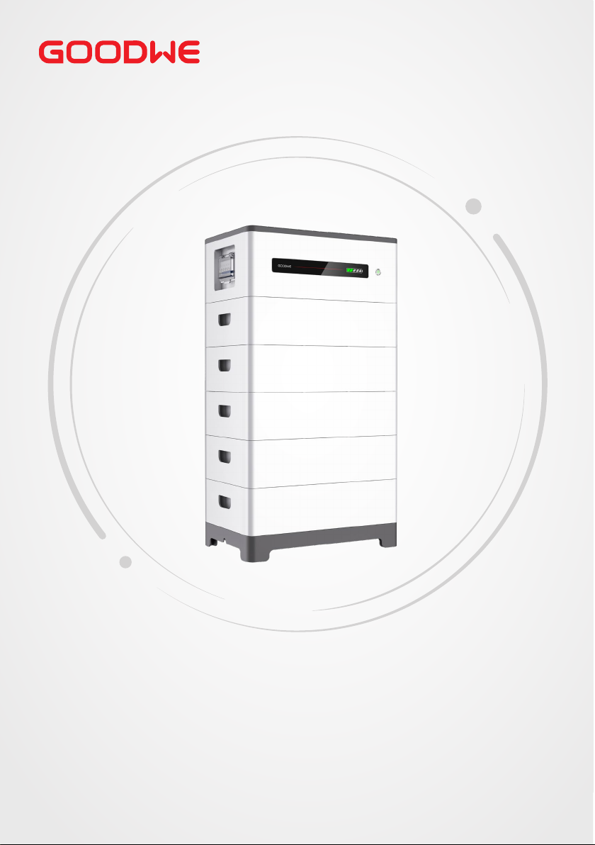
User Manual
Rechargeable Li-ion Battery System
Lynx Home F Series | Lynx Home F Plus+ Series
V1.6-2022-12-15
Page 2

Copyright StatementUser Manual V1.6-2022-12-15
Trademarks
and other GOODWE trademarks are trademarks of GoodWe Technologies
Co.,Ltd. All other trademarks or registered trademarks mentioned in this manual are owned by
GoodWe Technologies Co.,Ltd.
NOTICE
The information in this user manual is subject to change due to product updates or other
reasons. This guide cannot replace the product labels or the safety precautions in the user
manual unless otherwise specied. All descriptions here are for guidance only.
Page 3

CONTENT
User Manual V1.6-2022-12-15
Content
1 About This Manual ................................................................IV
1.1 Applicable Model ...........................................................................................IV
1.2 Target Audience .............................................................................................IV
1.3 Symbol Denition ..........................................................................................IV
1.4 Updates ...........................................................................................................V
2 Safety Precaution ................................................................ 01
2.1 General Safety ...............................................................................................01
2.2 Battery Safety ...............................................................................................02
2.3 Emergency Measures ...................................................................................04
2.4 EU Declaration of Conformity ......................................................................04
3 Product Introduction ........................................................... 05
3.1 Product Overview .........................................................................................05
3.2 Application Scenarios ..................................................................................06
3.3 Appearance ...................................................................................................07
3.4 Dimensions ...................................................................................................09
4 Check and Storage ............................................................... 10
4.1 Check Before Receiving ................................................................................10
4.2 Deliverables ..................................................................................................10
4.3 Storage ..........................................................................................................11
5 System Installation .............................................................. 12
5.1 Installation Requirements ...........................................................................12
5.2 Installing the Battery System .......................................................................14
5.2.1 Moving the Equipment ......................................................................................... 14
5.2.2 Installing the Battery System ............................................................................... 14
5.2.3 Installing the Power Control Unit ........................................................................ 17
6 Electrical Connection ........................................................... 19
6.1 Safety Precaution .........................................................................................19
6.2 Electrical Connection ...................................................................................20
6.3 Connecting the PE cable ..............................................................................21
6.4 Connecting the Power Cable .......................................................................22
6.5 Connecting the Communication Cable ......................................................26
6.6 Connecting the Terminal Resistor ...............................................................29
6.7 Installing the Protection Cover ....................................................................31
7 System Operation ................................................................ 32
II
Page 4

User Manual V1.6-2022-12-15User Manual V1.6-2022-12-15
7.1 Check Before Power ON ...............................................................................32
7.2 Power ON the Battery System .....................................................................32
7.3 Setting the Battery Parameters ...................................................................34
7.4 Indicator Status ............................................................................................35
7.4.1 Normal Status ........................................................................................................ 35
7.4.2 Alarming Status ..................................................................................................... 36
7.4.3 Faulty Status .......................................................................................................... 37
8 Maintenance ....................................................................... 39
8.1 Power OFF the Battery System ....................................................................39
8.2 Routine Maintenance ...................................................................................39
9 Parameters .......................................................................... 40
CONTENT
III
Page 5
Disclaimer User Manual V1.6-2022-12-15
1 About This Manual
This manual describes the product information, installation, electrical connection,
commissioning, troubleshooting and maintenance. Read through this manual before
installing and operating the product. All the installers and users have to be familiar with the
product features, functions, and safety precautions. This manual is subject to update without
notice. For more product details and latest documents, visit https://en.goodwe.com.
1.1 Applicable Model
This manual applies to the listed models below:
• LX F6.6-H
• LX F9.8-H
• LX F13.1-H
• LX F16.4-H
1.2 Target Audience
This manual applies to trained and knowledgeable technical professionals. The technical
personnel has to be familiar with the product, local standards, and electric systems.
1.3 Symbol Denition
Dierent levels of warning messages in this manual are dened as follows:
DANGER
Indicates a high-level hazard that, if not avoided, will result in death or serious injury.
WARNING
Indicates a medium-level hazard that, if not avoided, could result in death or serious injury.
CAUTION
Indicates a low-level hazard that, if not avoided, could result in minor or moderate injury.
NOTICE
Highlights and supplements the texts. Or some skills and methods to solve product-related
problems to save time.
IV
Page 6

1.4 Updates
The latest document contains all the updates made in earlier
issues.
V1.0 2022-07-20
• First Issue
V1.1 2021-12-20
• Updates 5.3 Installing the Battery System
V1.2 2022-02-18
• Updates 2.2 Symbol Description
• Updates 4.2 Packing List
• Updates 5.4 Electrical Connection
• Updates 6.4 Indicator Status
• Updates 07 Technical Parameters
V1.3 2022-08-20
• Updates Battery Cluster Application Scenarios.
V1.4 2022-10-20
• Updates 3.1 Product Overview.
V1.5 2022-11-20
• Updates 7.2 Power ON the Battery System.
V1.6 2022-12-15
• Updates 3.4 Dimensions.
• Updates 4.2 Deliverables.
• Updates 5.2 Installing the Battery System.
• Updates 6 Electrical Connection.
DisclaimerUser Manual V1.6-2022-12-15
V
Page 7
User Manual V1.6-2022-12-15
02 Safety Precaution
2 Safety Precaution
Please strictly follow these safety instructions in the user manual during the operation.
NOTICE
The products are designed and tested strictly to comply with related safety rules. Read and
follow all the safety instructions and cautions before any operations. Improper operation might
cause personal injury or property damage as the products are electrical equipment.
2.1 General Safety
NOTICE
• The information in this user manual is subject to change due to product updates or other
reasons. This guide cannot replace the product labels or the safety precautions in the user
manual unless otherwise specied. All descriptions here are for guidance only.
• Before installations, read through the user manual to learn about the product and the
precautions.
• All operations should be performed by trained and knowledgeable technicians who are
familiar with local standards and safety regulations.
• Use insulating tools and wear personal protective equipment (PPE) when operating the
equipment to ensure personal safety. Wear anti-static gloves, cloths, and wrist strips when
touching electronic devices to protect the equipment from damage.
• Strictly follow the installation, operation, and conguration instructions in this manual. The
manufacturer shall not be liable for equipment damage or personal injury if you do not
follow the instructions. For more warrant information, please visit: https://en.goodwe.com/
warranty.
01
Page 8
02 Safety Precaution
User Manual V1.6-2022-12-15
2.2 Battery Safety
DANGER
• The battery system exists high voltage during the equipment running. Please keep Power
O before any operations to avoid danger. Strictly follow all safety precautions outlined in
this manual and safety labels on the equipment during the operation.
• The inverter used with the battery shall be approved by the battery manufacturer. The
approved list of battery and the matched inverter can be obtained through the ocial
website.
• Do not disassemble, modify, or replace any part of the battery or the power control unit
without ocial authorization from the manufacturer. Otherwise, it will cause electrical
shock or damages to the equipment, which shall not be borne by the manufacturer.
• Do not hit, pull, drag, squeeze or step on the equipment or put the battery into re.
Otherwise, the battery may explode.
• Do not place the battery in a high temperature environment. Make sure that there is
no direct sunlight and no heat source near the battery. When the ambient temperature
exceeds 60 ℃, it will cause re.
• Do not use the battery or the power control unit if it is defective, broken, or damaged.
Damaged battery may leak electrolyte.
• To protect the battery pack and its components from damage during transportation,
please ensure that the transportation personnel are professionally trained. All operations
during the transportation have to be recorded. The equipment shall be kept in balance,
thus avoiding falling down.
• The battery equipment is heavy. Please equip the corresponding personnel according to its
weight, so that the equipment does not exceed the weight range of the human body can
carry, and cause personnel injury.
• Contact after-sale service immediately if the battery is not able to be started. Otherwise,
the battery might be damaged permanently.
• Do not move the battery system if it is connected with external battery modules. Contact
after-sales service if the battery shall be replaced or added.
CAUTION
• Protect the battery system from damage during transportation and storage.
• The transportation must be carried out by trained professionals. All operations during the
process have to be recorded.
• Keep the equipment stable to avoid dumping, which can result in equipment damage and
personal injuries.
• Place the cables at least 30mm away from the heating components or heat sources,
otherwise the insulation layer of the cables may be aging or broken due to high
temperature.
• Tie the cables of the same type together, and place cables of dierent types at least 30mm
apart. Do not place the cables entangled or crossed.
02
Page 9
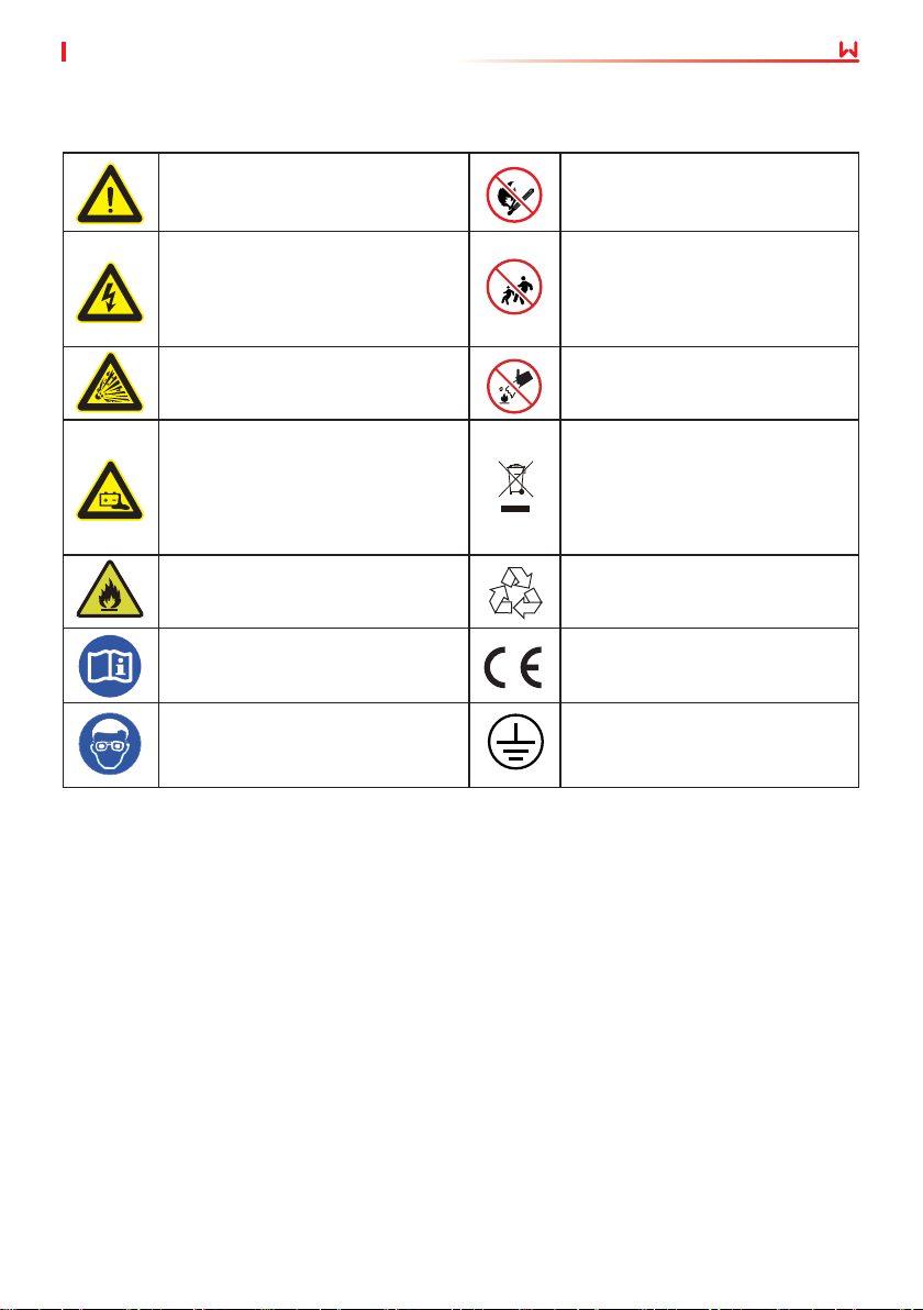
User Manual V1.6-2022-12-15
Label Description
02 Safety Precaution
Potential risks exist. Wear proper
HIGH VOLTAGE HAZARD. High
personnel protective equipment
before any operations.
voltage exists during the
equipment’s running.
Ensure the equipment is power o
before any operations.
Operate the equipment properly to
avoid explosion danger.
The equipment contains corrosive
electrolytes. In case of a leak in
the equipment, avoid contact the
leaked liquid or gas.
Batteries contain ammable
materials, beware of re.
Read through the user manual
before any operations.
Pay attention to wear PPE during
installation, operation and
maintaining of the equipment.
Install the equipment away from
re sources.
Keep the equipment away from
children.
No extinguishing with water.
Do not dispose of the equipment
with household garbage at its end
of life.
Dispose it according to local laws
and regulations
or send it to the manufacturer.
Recycle regeneration mark.
CE certication mark
Grounding point.
03
Page 10

02 Safety Precaution
User Manual V1.6-2022-12-15
2.3 Emergency Measures
Battery Electrolyte Leakage
If the battery module leaks electrolyte, avoid contact with the leaking liquid or gas. The
electrolyte is corrosive. It will cause skin irritation or chemical burn to the operator. Anyone
contact the leaked substance accidentally has to do as following:
• Breath in the leaked substance: Evacuate from the polluted area, and seek immediate
medical assistance.
• Eye contact: Rinse your eyes for at least 15 minutes with clean water and seek immediate
medical assistance.
• Skin contact: Thoroughly wash the touch area with soap and clean water, and seek
immediate medical assistance.
• Ingestion: Induce vomiting, and seek immediate medical assistance.
Fire
• The battery may explode when the ambient temperature exceeds 150℃. Poisonous and
hazard gas may be released if the battery is on re.
• In the event of a re, please make sure that the carbon dioxide extinguisher or Novac1230 or
FM-200 is nearby.
• The re cannot be put out by water or ABC dry powder extinguisher. Fireghters are required
to wear full protective clothing and self-contained breathing apparatus.
2.4 EU Declaration of Conformity
GoodWe Technologies Co., Ltd. hereby declares that the inverter without wireless
communication modules sold in the European market meets the requirements of the following
directives:
• Electromagnetic compatibility Directive 2014/30/EU (EMC)
• Electrical Apparatus Low Voltage Directive 2014/35/EU (LVD)
• Battery Directive 2006/66/EC and Amending Directive 2013/56/EU
• Waste Electrical and Electronic Equipment 2012/19/EU
• Registration, Evaluation, Authorization and Restriction of Chemicals (EC) No 1907/2006
(REACH)
You can download the EU Declaration of Conformity on the ocial website:https://en.goodwe.
com.
04
Page 11
03 Product IntroductionUser Manual V1.6-2022-12-15
3 Product Introduction
3.1 Product Overview
Intended usage
The battery system, which consists of a power control unit (PCU for short) and battery modules,
can store and release the electric energy according to the requirements of the solar energy
storage system. The input and output ports of the energy storage system are high voltage direct
current ports.
Usable energy description
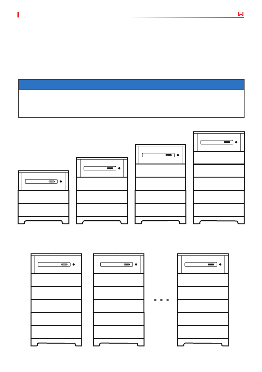
NOTICE
The battery system supports capacity expansion. A maximum of 5 battery modules can
be used to extend the usable energy of the battery system. Strictly follow the expansion
requirement. For details, please contact the Dealer or Manufacturer. Otherwise, undervoltage,
overvoltage or voltage dierence might occur to the battery system.
16.38 kWh
PCU
Battery 5
Battery 4Battery 4
Battery 3Battery 3
6.55kWh
PCU
9.83kWh
PCU
Battery 3
13.10kWh
PCU
Battery 2 Battery 2 Battery 2 Battery 2
Battery 1 Battery 1 Battery 1 Battery 1
LX F6.6-H
A max of eight battery systems can be parallel connected in one energy storage system. Ensure
that the usable energy of each battery system is the same.
Battery system 1 Battery system 2 Battery system N
LX F9.8-H
05
LX F13.1-H
2≤N≤ 8
LX F16.4-H
Page 12
03 Product Introduction User Manual V1.6-2022-12-15
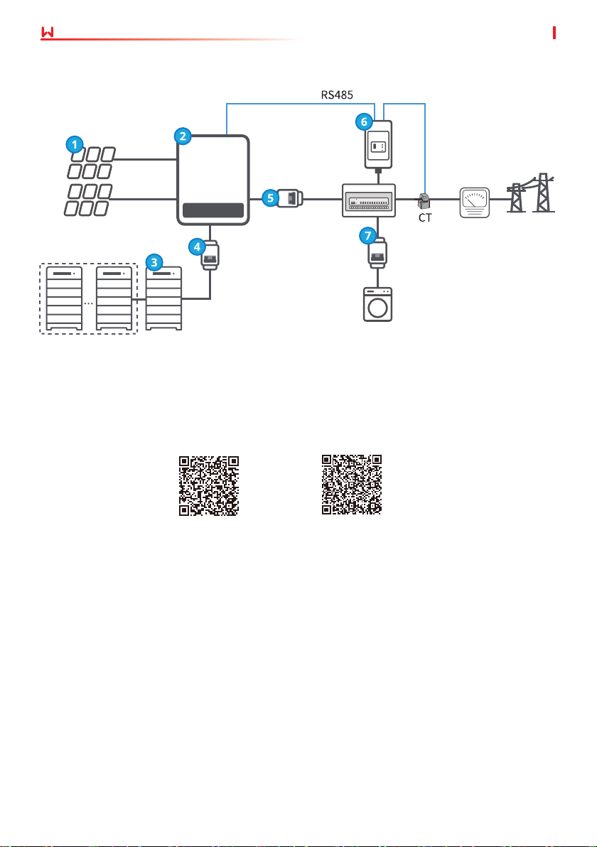
3.2 Application Scenarios
Smart
meter
Inverter
AC circuit
Battery
breaker
breaker
AC circuit
breaker
Loads
PV string
Battery
system N
Approved inverter list
Scan the QR code below or visit the ocial website to get the Approved Battery Options
Statement.
Battery
system 1
GoodWe Inverter GE Inverter
Smart
meter
Utility grid
06
Page 13
User Manual V1.6-2022-12-15
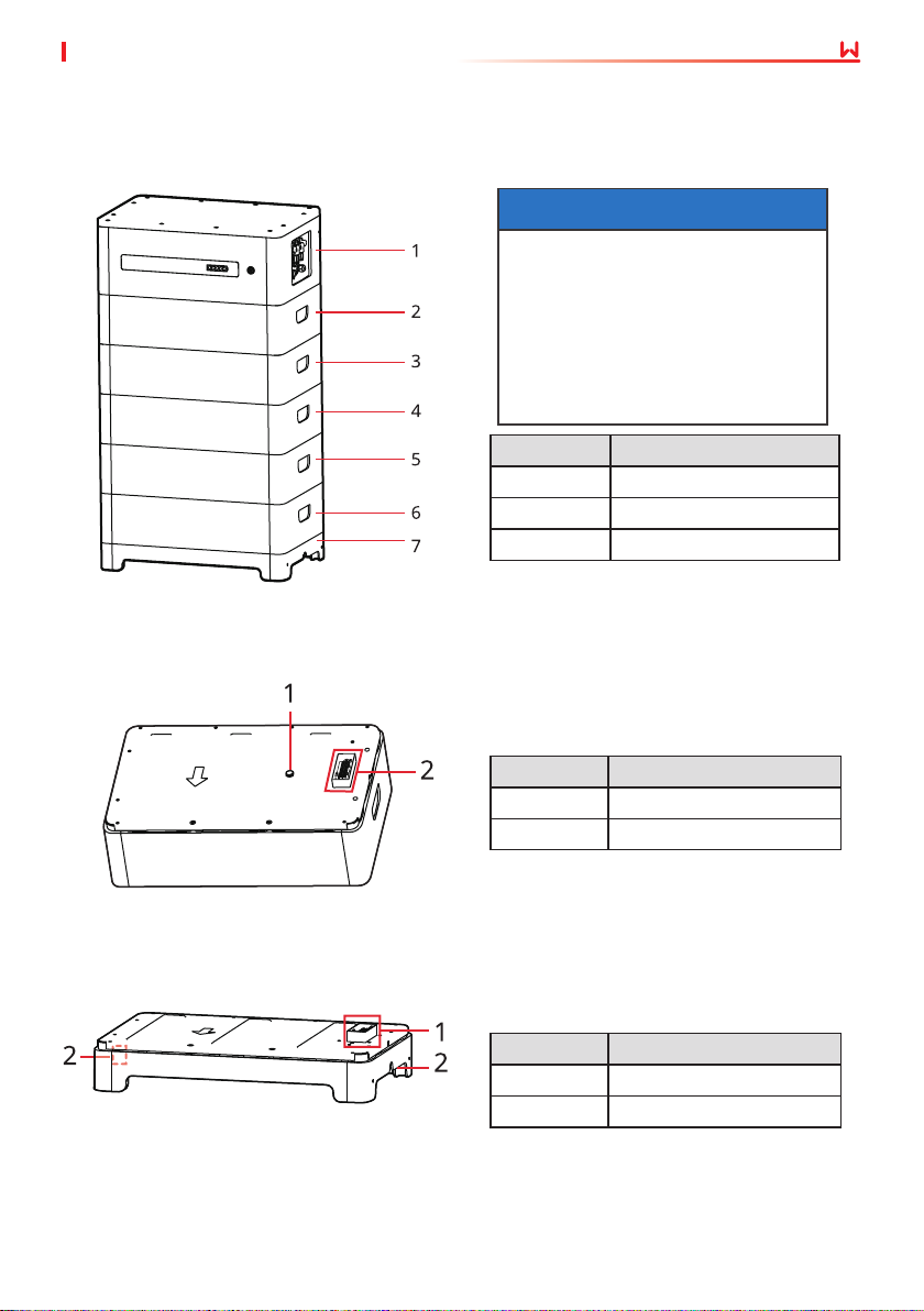
3.3 Appearance
Battery system appearance
04 Check and Storage
NOTICE
• Ensure that the PCU is installed
above the battery modules. Do
not install any battery modules
above the PCU.
• This manual will show you
the installation and electrical
connection of 5 battery modules.
No. Parts
1 PCU
2, 3, 4, 5, 6 Battery
7 Base
Battery appearance
Base appearance
No. Parts
1 Ventilation valve
2 Rectangular connector
No. Parts
1 Rectangular connector
2 Grounding point
07
Page 14
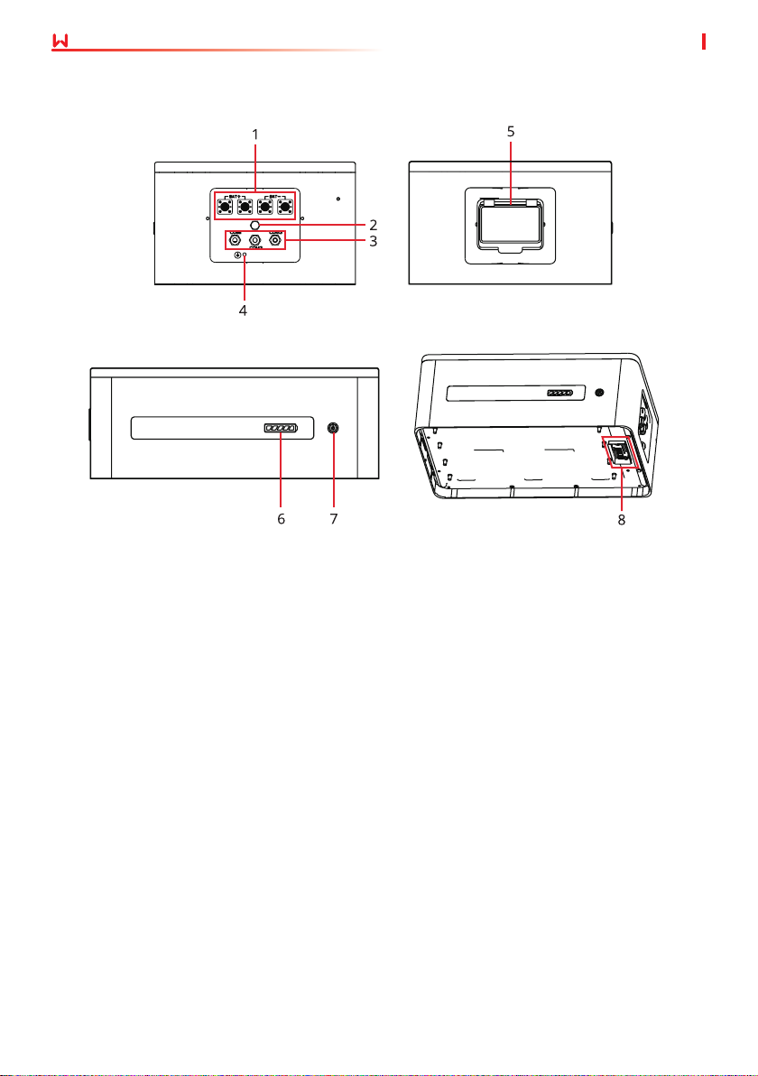
04 Check and Storage
Power control unit appearance
User Manual V1.6-2022-12-15
Right View
Left View
Front View Bottom View
1. DC terminal (BAT) 2. Ventilation valve 3.
Communication terminal
[1]
(COM)
4. Grounding point 5 Air switch 6. SOC indicator
Multifunction button
7.
indicator
[2]
Battery serial connection
8.
interface
[1]. Some models do not have the COM3 terminal, which is designed for battery system parallel
connection.
[2]. The multifunction button indicator is designed as an indicator, black start switch, and power
o button.
08
Page 15
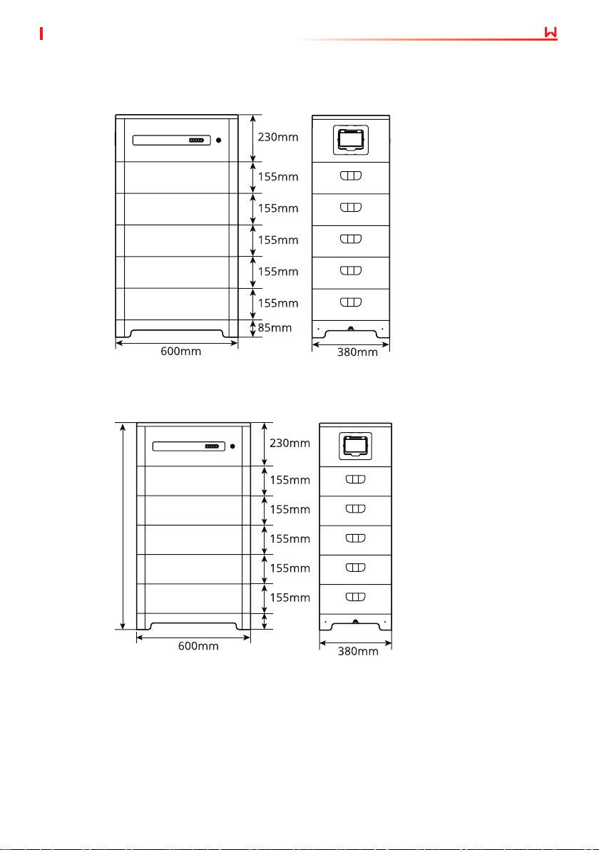
3.4 Dimensions
Lynx home F series
Lynx home F Plus+ series
05 System InstallationUser Manual V1.6-2022-12-15
1075mm
70mm
09
Page 16
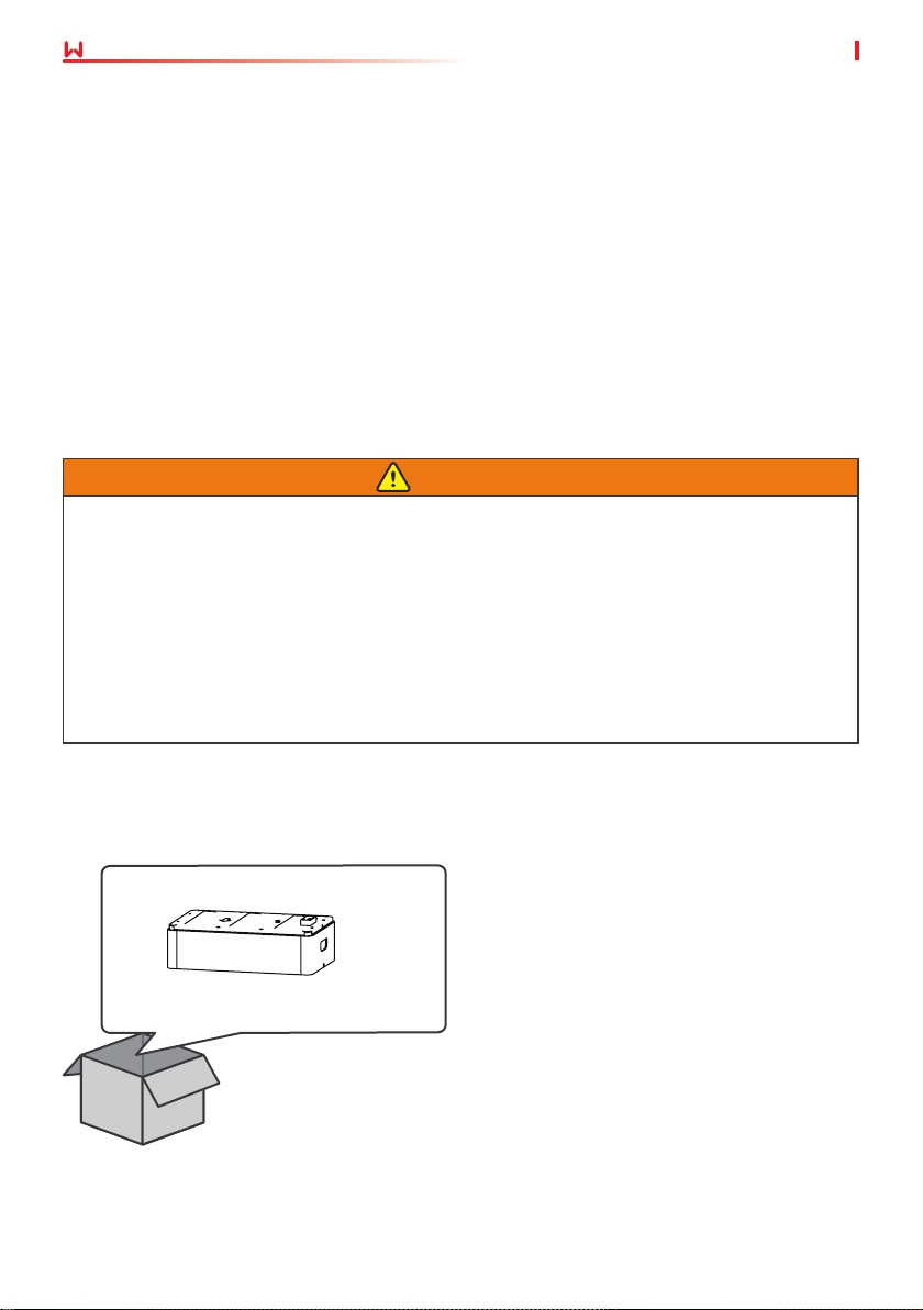
05 System Installation User Manual V1.6-2022-12-15
4 Check and Storage
4.1 Check Before Receiving
Check the following items before receiving the product.
1. Check the outer packing box for damage, such as holes, cracks, deformation, and other
signs of equipment damage. Do not unpack the package and contact the supplier as soon as
possible if any damage is found.
2. Check the product model. If the product model is not what you requested, do not unpack the
product and contact the supplier.
3. Check the deliverables for correct model, complete contents, and intact appearance. Contact
the supplier as soon as possible if any damage is found.
4.2 Deliverables
WARNING
• The adjustable feet are only for Lynx home F Plus+ series.
• The adjustable feet are optional. If you choose to install the battery system using the feet,
four pieces of adjustable feet will be provided by default.
• The locking bracket will be dierent to match the adjustable feet. You can select the locking
bracket based on your requirements.
• If you choose to use the adjustable feet, two locking brackets match the feet and two
normal locking brackets will be provided by default except for the four adjustable feet.
• If you do not need the adjustable feet, four normal locking brackets will be provided by
default.
Battery module
Battery module x 1
10
Page 17
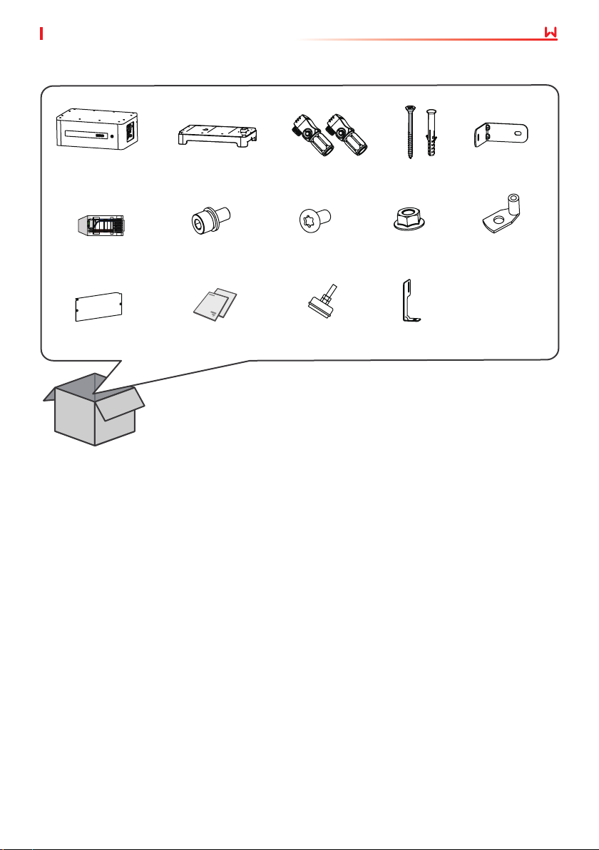
Power control unit
05 System InstallationUser Manual V1.6-2022-12-15
PCU x 1
Terminal resistor x 1
Protection cover x 1
Base x 1 DC connector x 1
M5*12 screw x 4
Documents x 1
M5 hexagon
screw x 2
Adjustable
feet x N
Expansion
bolt x 4
M6 screw x 2
Locking bracket (match
adjustable feet) x N
Normal locking
bracket x N
Grounding
terminal x 2
4.3 Storage
If the equipment is not to be installed or used immediately, please ensure that the storage
environment meets the following requirements:
1. Do not unpack the outer packing box or throw the desiccant away.
2. Complete the equipment installation in three days after unpacking it. Pack and store the
equipment using the original packing box if it is not installed.
3. Stack the equipment complying with the labels and requirements on the packing box.
4. The equipment must be stacked with caution to prevent them from falling.
5. Keep the equipment away from ammable, explosive, and corrosive matters.
6. Place the equipment in a cool place where away from direct sunlight.
7. Store the equipment in a clean place. Make sure the temperature and humidity are
appropriate and no condensation.
8. Storage SOC: 25%~50% SOC. Circle the charge-discharge every 3 months.
9. Recommended storage temperature: -20~45℃ (less than one month) or 0℃~35℃ (less than
one year).
10. Recommended storage humidity: 0%~95%RH(no condensation). Do not install the battery if
there is any moisture or condensation.
11
Page 18
05 System Installation User Manual V1.6-2022-12-15
5 System Installation
5.1 Installation Requirements
Installation Environment Requirements
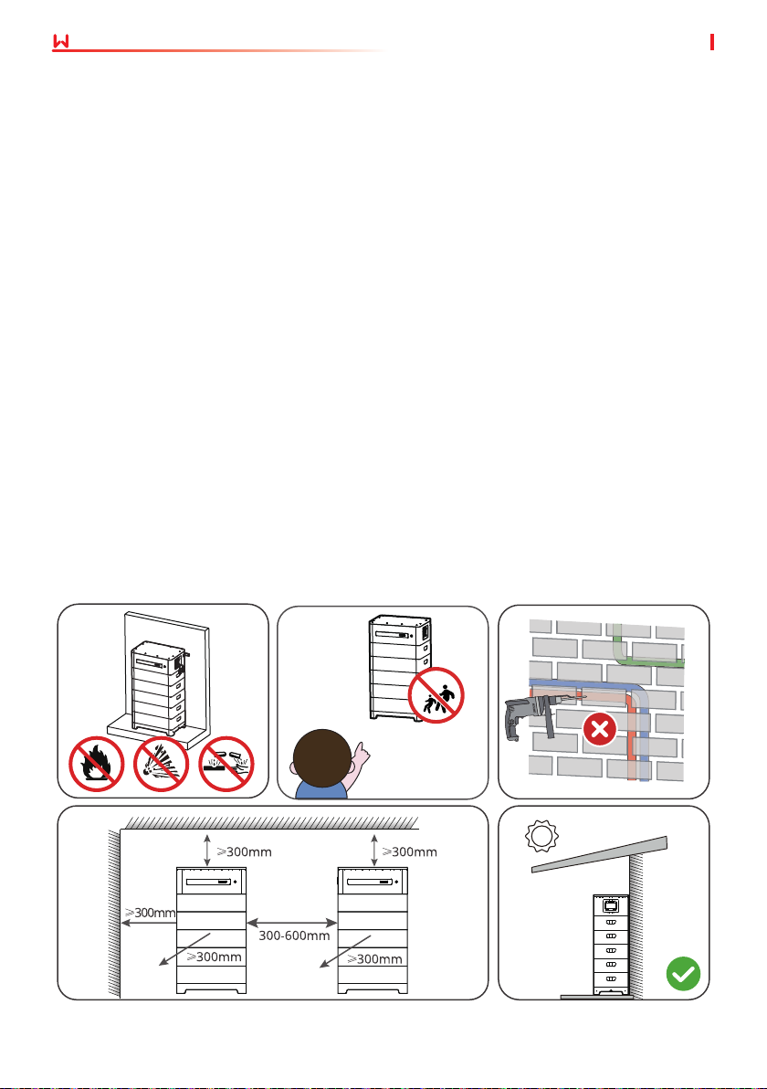
1. Do not install the equipment in a place near ammable, explosive, or corrosive materials.
2. Do not install the equipment in a place that is easy to touch, especially within children’s reach.
High temperature exists when the equipment is working. Do not touch the surface to avoid
burning.
3. Avoid the water pipes and cables buried in the wall when drilling holes.
4. Install the equipment in a sheltered place to avoid direct sunlight, rain, and snow. Build a
sunshade if it is needed.
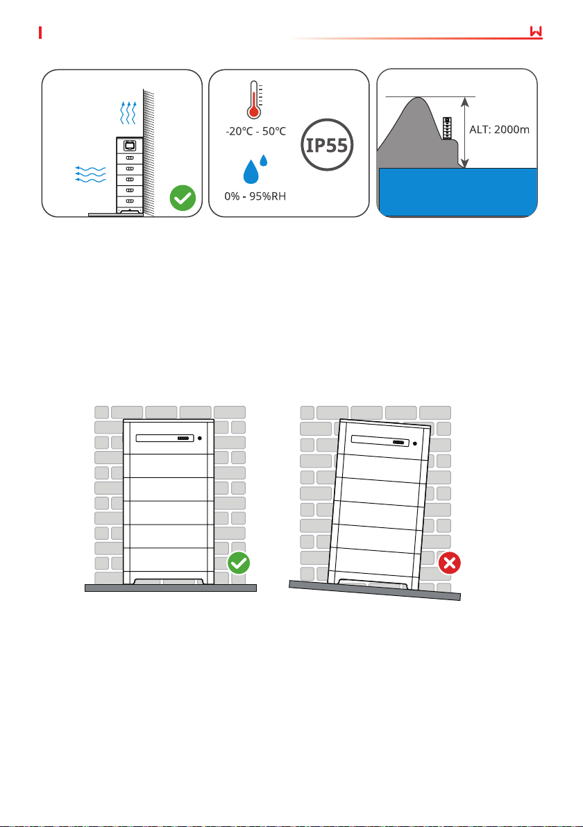
5. Install the equipment in a well-ventilated place to ensure good dissipation. Also, the
installation space should be large enough for operations.
6. The equipment with a high ingress protection rating can be installed indoors or outdoors.
The temperature and humidity at the installation site should be within the appropriate range.
7. Install the equipment at a height that is convenient for operation and maintenance, electrical
connections, and checking indicators and labels.
8. The altitude to install the equipment shall be lower than the maximum working altitude
2000m.
9. Install the equipment away from electromagnetic interference. If there is any radio or
wireless communication device below 30MHz near the equipment, make sure that the
equipment is at least 30m far away from the wireless device.
Prevent Child
Access
12
Page 19
05 System InstallationUser Manual V1.6-2022-12-15
Mounting Support Requirements
• The mounting support shall be nonammable and reproof.
• Install the equipment on a surface that is solid enough to bear the product weight.
• Put the battery system near the wall and install the locking brackets to prevent the battery
from falling down.
Installation Angle Requirements
• Install the equipment vertically, no tilt or upside down.
13
Page 20
05 System Installation User Manual V1.6-2022-12-15
5.2 Installing the Battery System
5.2.1 Moving the Equipment
CAUTION
• Operations such as transportation, turnover, installation and so on must meet the
requirements of the laws and regulations of the country or region where it is located.
• Move the equipment to the site before installation. Follow the instructions below to avoid
personal injury or equipment damage.
1. Consider the weight of the equipment before moving it. Assign enough personnel to
move the equipment to avoid personal injury.
2. Wear safety gloves to avoid personal injury.
3. Keep balance to avoid falling down when moving the equipment.
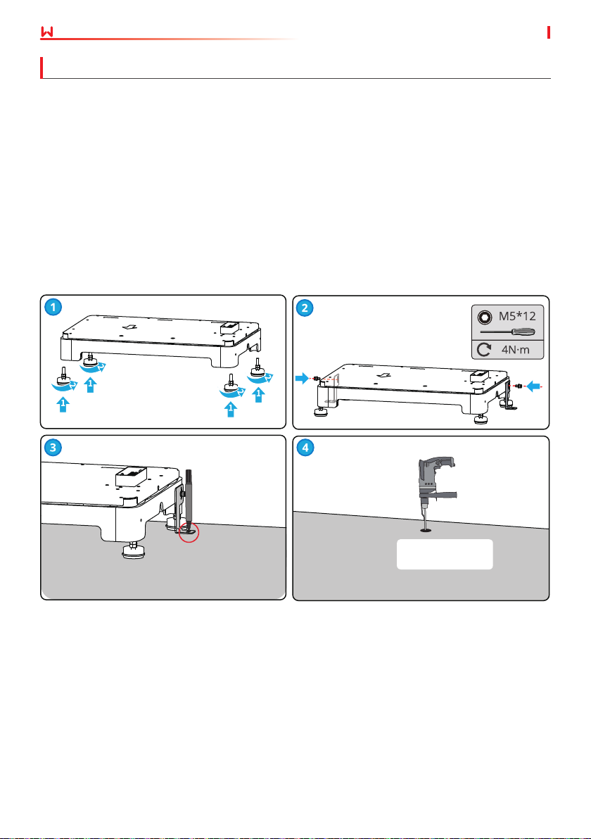
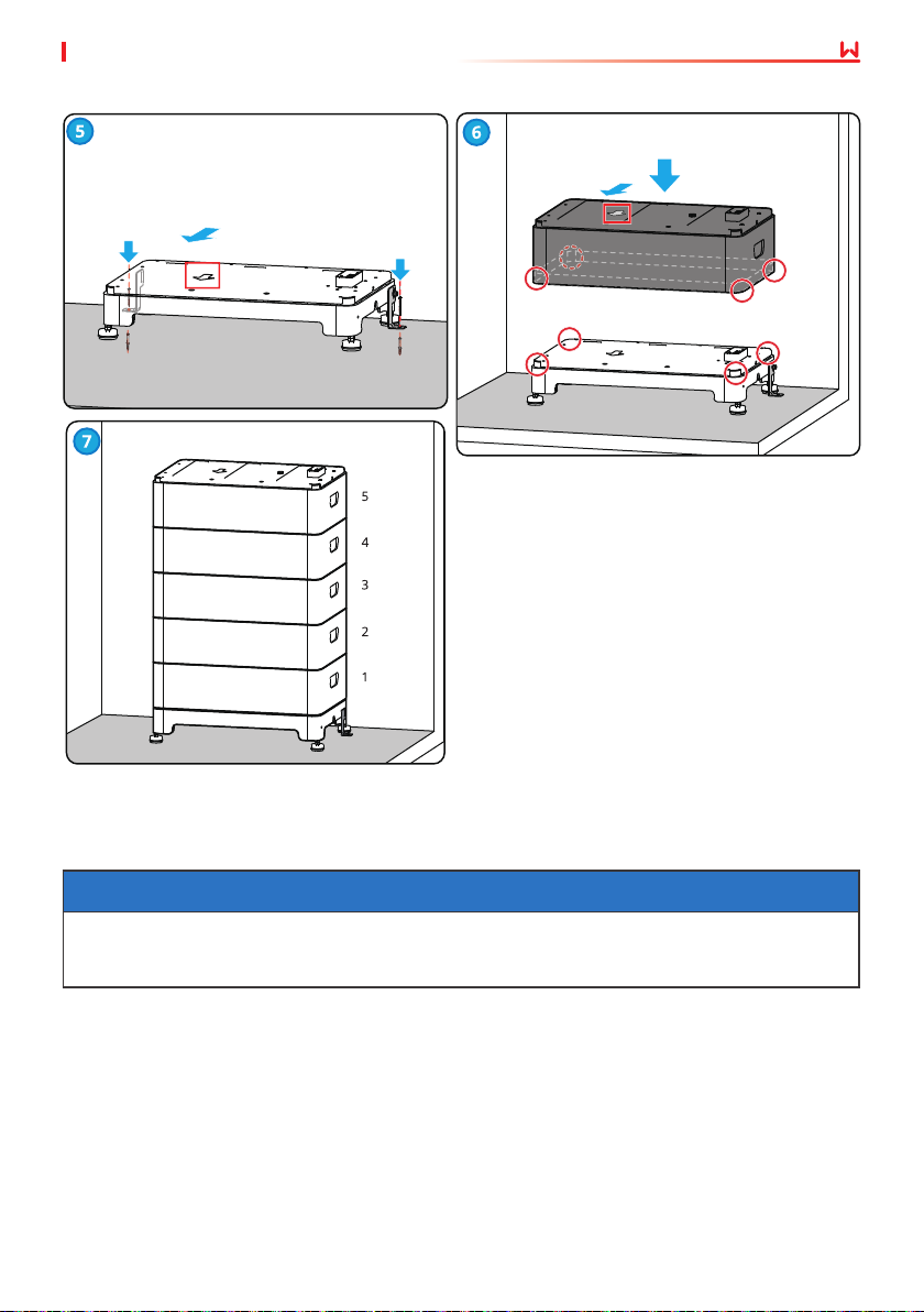
5.2.2 Installing the Battery System
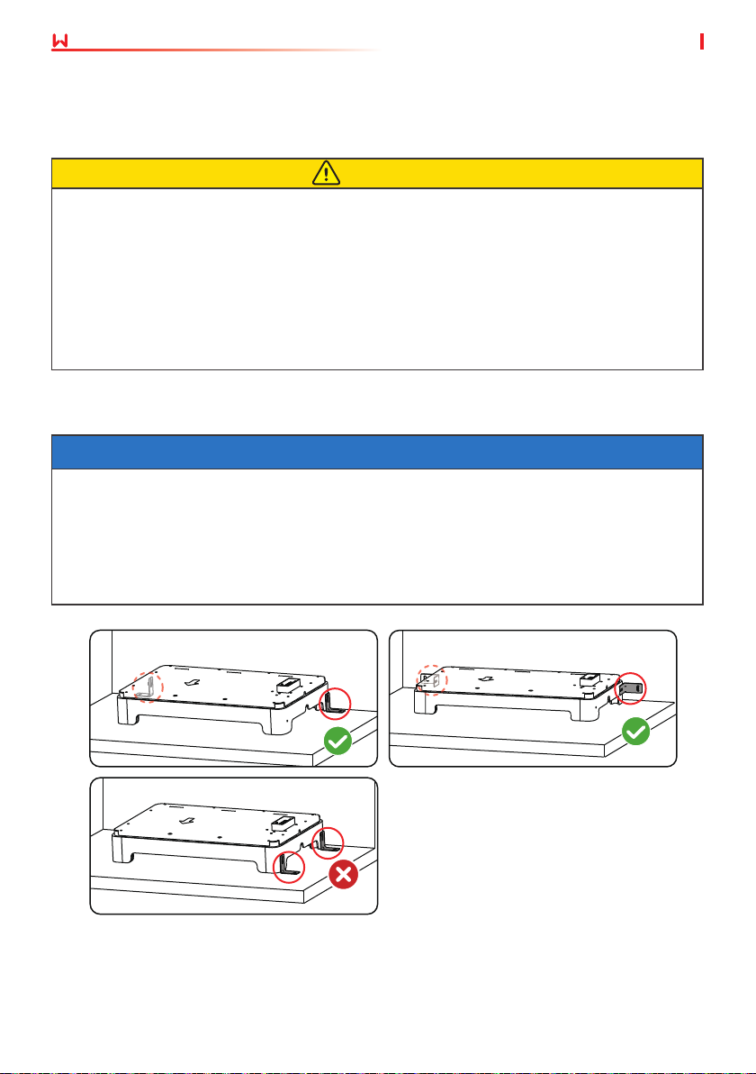
NOTICE
• Ensure that the base stands on the oor vertically.
• Ensure that the base clings to the wall and the arrow points outward.
• Ensure that all batteries cling to the wall and the arrow points outward.
• Align the holes of the upper and the lower battery modules when placing the upper battery
module.
• Ensure that the locking bracket clings to the wall.
• Do not install the two locking brackets on one side.
14
Page 21
05 System InstallationUser Manual V1.6-2022-12-15
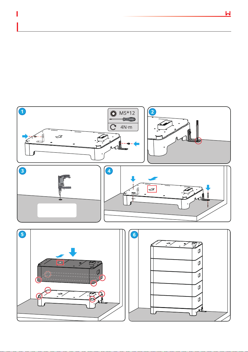
Installing the Battery System (Without Adjustable Feet)
Step 1: Install the locking brackets to the base.
Step 2: Place the base cling to the wall and mark the drilling positions. Then remove the base.
Step 3: Drill holes using the hammer drill.
Step 4: Screw the expansion bolts to x the base. Ensure that the base is installed in the correct
direction.
Step 5: Place the battery module on the base, and ensure that the base and the battery are
installed in the same direction.
Step 6: Install the remaining batteries according to actual battery system type.
Diameter: 10mm
Depth: 80mm
15
Page 22
05 System Installation User Manual V1.6-2022-12-15
Installing the Battery System (With Adjustable Feet)
Only for Lynx home F Plus+ series.
Step 1: Install the adjustable feet to the base.
Step 2: Install the locking brackets to the base.
Step 3: Place the base cling to the wall and mark the drilling positions. Then remove the base.
Step 4: Drill holes using the hammer drill.
Step 5: Screw the expansion bolts to x the base. Ensure that the base is installed in the correct
direction.
Step 6: Place the battery module on the base, and ensure that the base and the battery are
installed in the same direction.
Step 7: Install the remaining batteries according to actual battery system type.
16
Diameter: 10mm
Depth: 80mm
Page 23
05 System InstallationUser Manual V1.6-2022-12-15
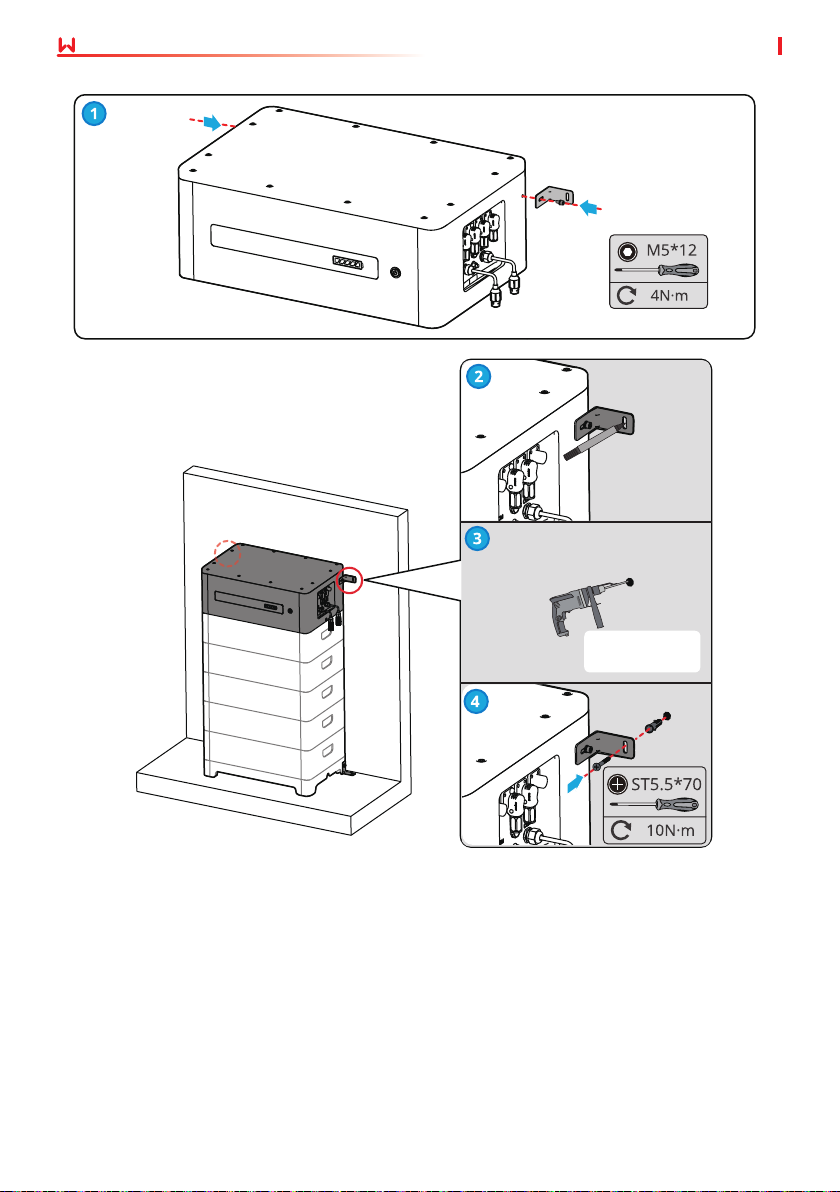
5.2.3 Installing the Power Control Unit
NOTICE
• Cover the equipment with a cardboard to prevent foreign matters when drilling holes.
• Put the locking bracket of the PCU cling to the wall, and ensure that the bottom of the PCU
is vertically and closely put on the battery.
Step 1: Install the locking brackets of the PCU.
Step 2: Put the PCU above the installed battery modules securely. Mark the drilling hole using a
marker, then remove the PCU.
Step 3: Drill holes using the hammer drill.
Step 4: Secure the locking brackets to prevent the PCU from falling down.
17
Page 24
05 System Installation User Manual V1.6-2022-12-15
18
Diameter: 10mm
Depth: 80mm
Page 25
User Manual V1.6-2022-12-15
6 Electrical Connection
6.1 Safety Precaution
06 Electrical Connection
DANGER
• The battery system exists high voltage during the equipment running.
O before any operations to avoid danger. Strictly follow all safety precautions outlined in
this manual and safety labels on the equipment during the operation.
• All operations, cables and parts specication during the electrical connection shall be in
compliance with local laws and regulations.
• Tie the same type cables together, and place them separately from cables of dierent types.
Do not place the cables entangled or crossed.
• Make sure that the cable conductor is in full contact with the terminal and the cable insulation
part is not crimped with the terminal when crimping the terminal. Otherwise, the device may
not be able to work properly, or the connection may be unreliable during working, which
may cause terminal block damage, etc.
NOTICE
• Wear personal protective equipment like safety shoes, safety gloves, and insulating gloves
during electrical connections.
• All electrical connections should be performed by qualied professionals.
• Cable colors in this document are for reference only. The cable specications shall meet local
laws and regulations.
Please keep Power
19
Page 26
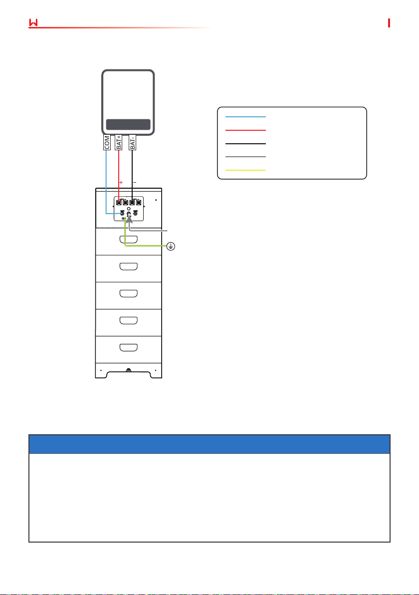
06 Electrical Connection
Single battery system
User Manual V1.6-2022-12-15
Inverter
Communication Cable
Power Cable for Positive Pole
Power Cable for Negative Pole
Terminal resistor
Ground Cable
Terminal
resistor
Battery System
6.2 Electrical Connection
NOTICE
• A max of eight battery systems can be parallel connected in one energy storage system.
Ensure that the usable energy of each battery system is the same.
• Install the terminal resistor to the COM3 port of Battery system 1, which is connected to
the inverter directly.
• Install the terminal resistor to the COM2 port of Battery system N, which is the last battery
system of the battery cluster system.
• The battery cluster interlock function will fail if the terminal resistor is not installed.
20
Page 27
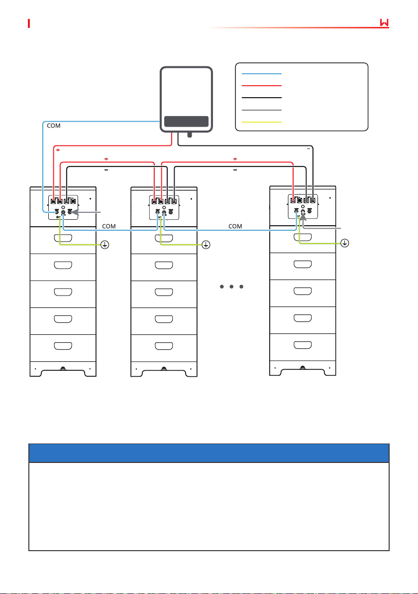
User Manual V1.6-2022-12-15
Parallized battery systems
Only for Lynx home F Plus+ series.
Terminal
resistor
06 Electrical Connection
Communication cable
Positive power cable
Negative power cable
Terminal resistor
PE cable
Terminal resistor
2≤N≤ 8
Battery system 1
Battery system 2
Battery system N
6.3 Connecting the PE cable
NOTICE
• Connect the PE cable rst before installing the equipment. Disconnect the PE cable before
dismantling the equipment.
• The drawing force of the cable after crimping should be at least 400N.
• Connect the PE cable to the PCU or to the base in the same way.
• The PE cable should be prepared by the customer. Recommended specications:
• Type: single-core outdoor copper cable
• Cross-sectional area: 4-6mm
2
21
Page 28
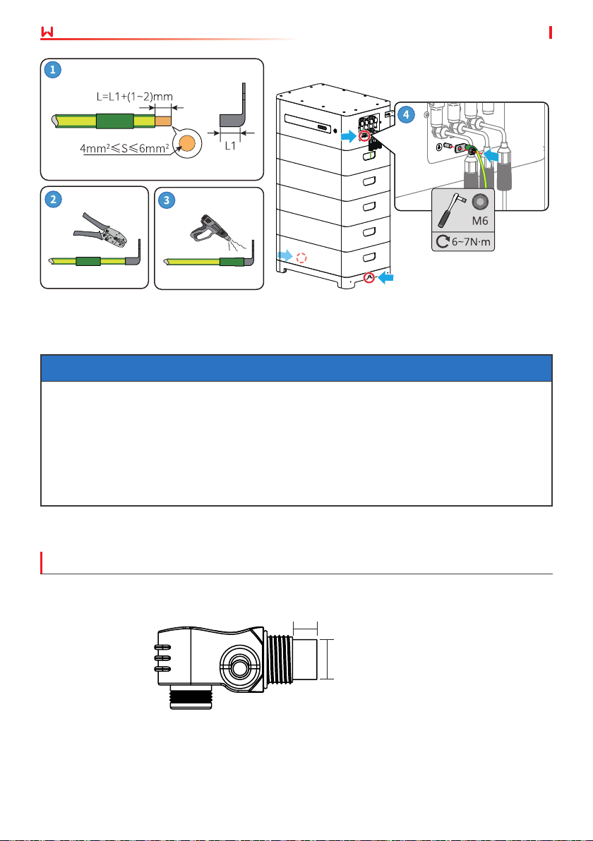
06 Electrical Connection
User Manual V1.6-2022-12-15
Grounding
point
6.4 Connecting the Power Cable
NOTICE
• Power o the battery system before connecting the power cable to avoid high voltage
danger.
• The DC input cable should be prepared by customers. Connect the red power connector to
the red wire harness. And the black power connector to the black wire harness. The cable
should meet standards for outdoor use.
• Install the back cover properly and make sure there is no space.
• The unused ports shall be protected using a cover.
Connecting the power cable (Type 1)
Crimping length: 7.5±0.2mm
22
Crimping hight:
7.5±0.2mm
Page 29
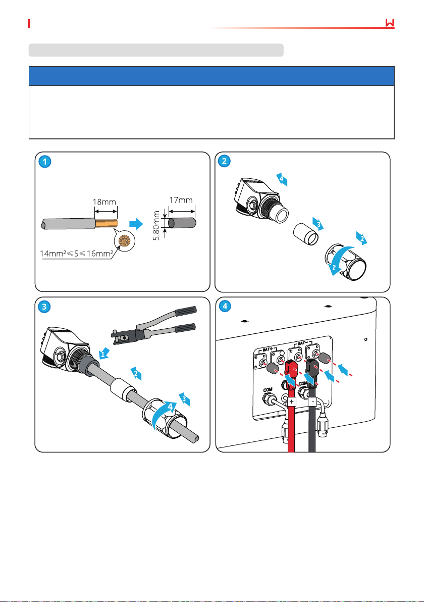
User Manual V1.6-2022-12-15
06 Electrical Connection
Cross-sectional area of the power cable S: 14mm2≤S≤16mm
2
NOTICE
• Recommended tool: manual hydraulic press plier. Crimping hight: 7mm; moulding: 16mm
• The drawing force of the cable after crimping should be at least 1200N.
• The copper tube should be prepared by customers. Copper tube length: 17mm, copper
tube inner diameter: 5.80mm.
2
23
Page 30
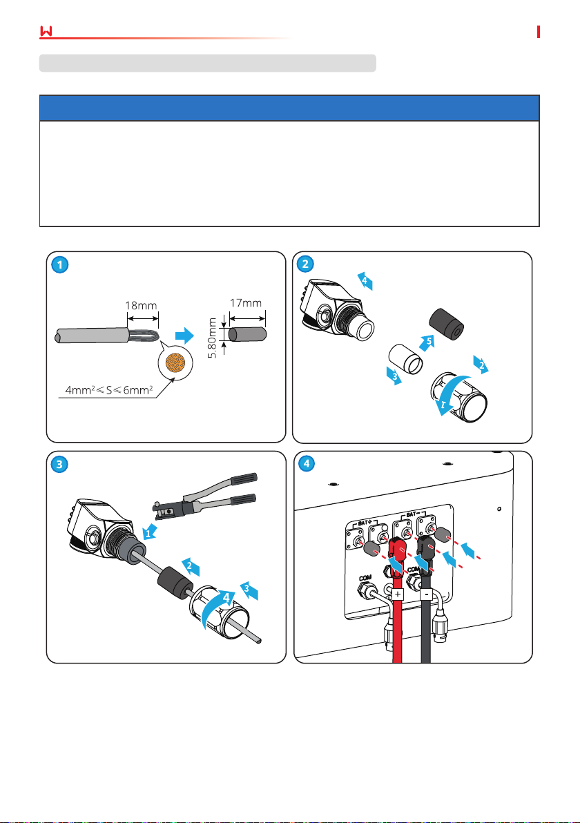
06 Electrical Connection
User Manual V1.6-2022-12-15
Cross-sectional area of the power cable S: 4mm2≤S≤6mm
2
NOTICE
• Replace the white seal ring inside the power connector with a black seal ring (inner
diameter 4.59mm) before crimping the power cable.
• Make sure the conductor cut is at after folding in half.
• The copper tube should be prepared by customers. Copper tube length: 17mm, copper
tube inner diameter: 5.80mm.
• The drawing force of the cable after crimping should be at least 500N.
24
Page 31
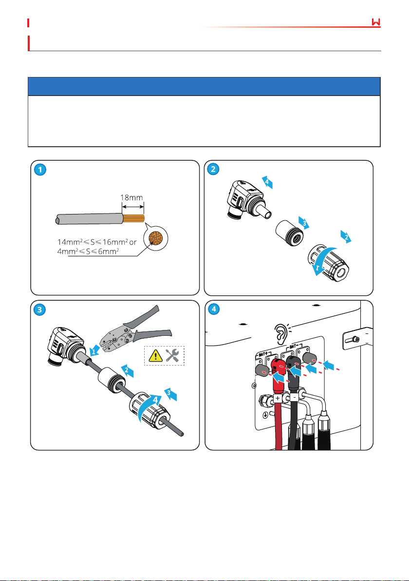
User Manual V1.6-2022-12-15
06 Electrical Connection
Connecting the power cable (Type 2)
Only for Lynx home F Plus+ series.
NOTICE
• The drawing force of the cable after crimping should be at least 1200N when the crosssectional area range of the cable is 14mm2≤S≤16mm2.
• The drawing force of the cable after crimping should be at least 500N when the crosssectional area range of the cable is 4mm2≤S≤6mm2.
25
Click
Page 32
06 Electrical Connection
User Manual V1.6-2022-12-15
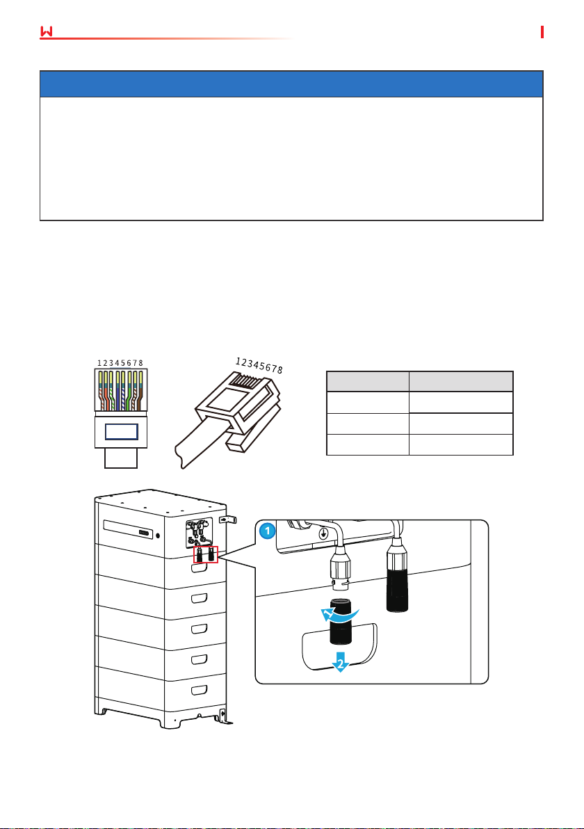
6.5 Connecting the Communication Cable
NOTICE
• The two battery communication ports have the same function.
• Connect the cable to any one of the two communication ports. And connect the terminal
resistor to the other port.
• For the EHB series and GE series inverters, the manufacturer does not supply the battery
communication cable.
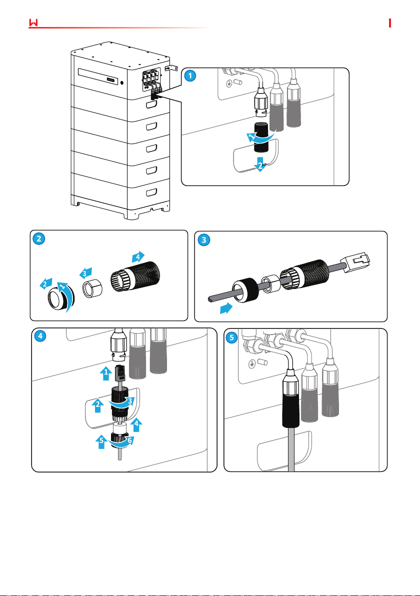
• Please refer to the following pin denitions if you need to make a new battery
communication cable.
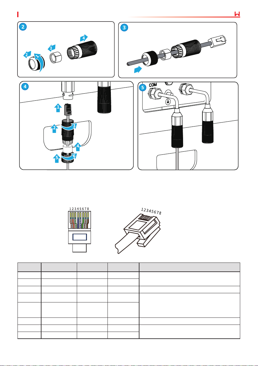
Step 1: Disassemble the waterproof module.
Step 2: Run the communication cable through the waterproof module.
Step 3: Connect the communication cable to the battery. Tighten the waterproof module.
Lynx home F series
RJ45 Connector
PIN Description
4 CAN_H
5 CAN_L
1,2,3,6,7,8 N/A
26
Page 33
User Manual V1.6-2022-12-15
Lynx home F Plus+ series
RJ45 Connector
06 Electrical Connection
PIN Denition
PIN COM1 COM2 COM3 Description
1 CAN_3H CAN_3H CAN_3H BMS communication for battery system
2 CAN_3L CAN_3L CAN_3L
3 N/A N/A N/A Reserved
4 CAN_2H N/A N/A
5 CAN_2L N/A N/A
6 GND GND GND PIN for grounding.
7 HVIL_IN HVIL_IN N/A
8 HVIL_OUT HVIL_OUT N/A
parallel connection
COM1: connects to the inverter BMS
communication port to communication
with the inverter
COM2, COM3: reserved
COM1, COM2: interlock function
COM3: reserved
27
Page 34
06 Electrical Connection
User Manual V1.6-2022-12-15
28
Page 35
User Manual V1.6-2022-12-15
06 Electrical Connection
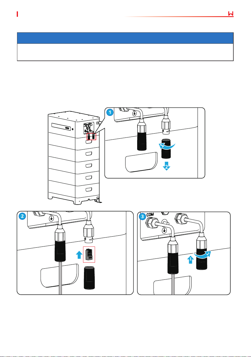
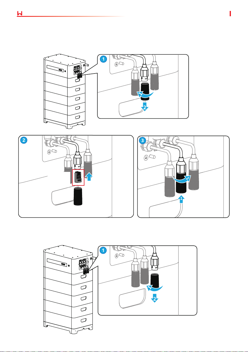
6.6 Connecting the Terminal Resistor
NOTICE
If the terminal resistor is not installed, the Interlock Failure will occur, and the system cannot
work correctly.
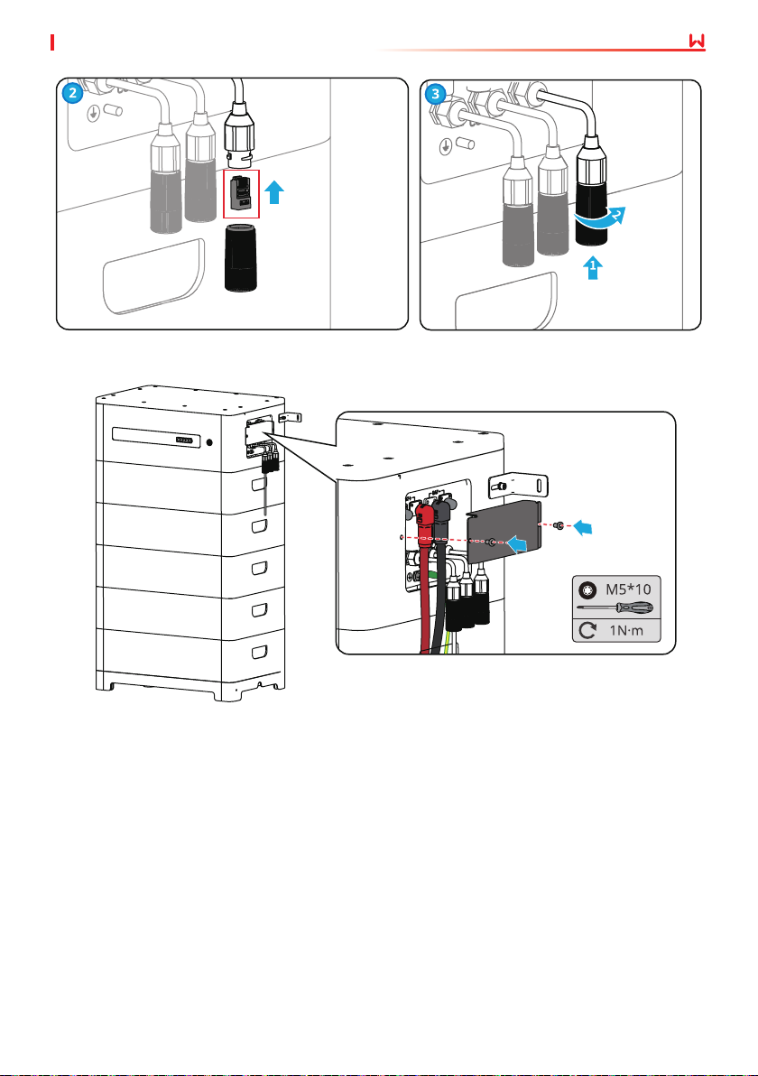
Step 1: Disassemble the waterproof module.
Step 2: Install the terminal resistor.
Step 3: Tighten the waterproof module.
Lynx home F series
29
Page 36
06 Electrical Connection
Lynx home F Plus+ series
Single battery system
Terminal
resistor
User Manual V1.6-2022-12-15
Parallized battery systems
30
Page 37
User Manual V1.6-2022-12-15
Terminal
resistor
6.7 Installing the Protection Cover
06 Electrical Connection
31
Page 38
07 Equipment Commissioning
User Manual V1.6-2022-12-15
7 System Operation
7.1 Check Before Power ON
Check the following items before power on to avoid the battery system being damaged.
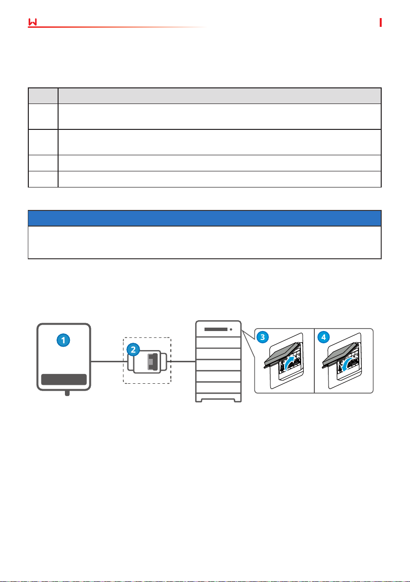
No. Check Item
The inverter is rmly installed in a clean place where is well-ventilated and easy to
1
operate.
The PE cable, power cable, communication cable, and terminal resistor are connected
2
correctly and securely.
3 Cable ties are intact, routed properly and evenly.
4 Unused ports and terminals are sealed.
7.2 Power ON the Battery System
NOTICE
• The DC breaker between the inverter and the battery (DC Breaker 2), and between the two
batteries (DC Breaker 5), shall be installed in accordance with local laws and regulations.
• The breaker should isolate both positive and negative conductors simultaneously.
Step 1: (Optional) Turn on the breaker between the inverter and the battery system.
Step 2: Turn on the air switch of the battery system.
Step 3: Turn on the inverter in the system following the instructions in the user manual of the
inverter.
Inverter
Breaker (only
for Australia)
Battery
System
32
Air switch
Page 39
User Manual V1.6-2022-12-15
07 Equipment Commissioning
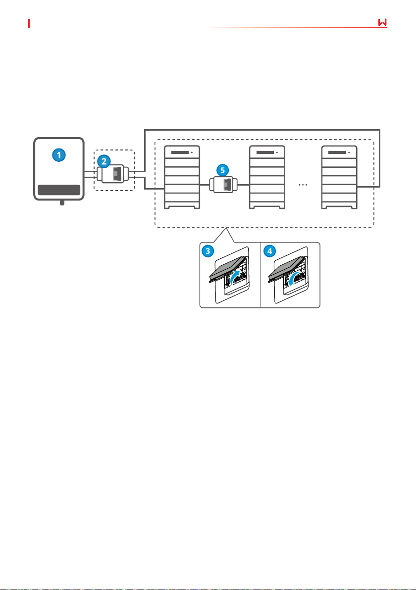
Parallized battery systems
Only for Lynx home F Plus+ series.
Step 1: (Optional) Turn on the breaker between the inverter and the battery system.
Step 2: Turn on the breakers between the battery systems.
Step 3: Turn on the air switches of the battery systems in turn.
Step 4: Turn on the inverter in the system following the instructions in the user manual of the
inverter.
Inverter
DC Breaker
(Only for Australia )
Battery
System 1
DC Breaker
(Only for
Australia )
Battery
System 2
2≤N≤ 8
Battery
System N
33
Page 40
07 Equipment Commissioning
User Manual V1.6-2022-12-15
7.3 Setting the Battery Parameters
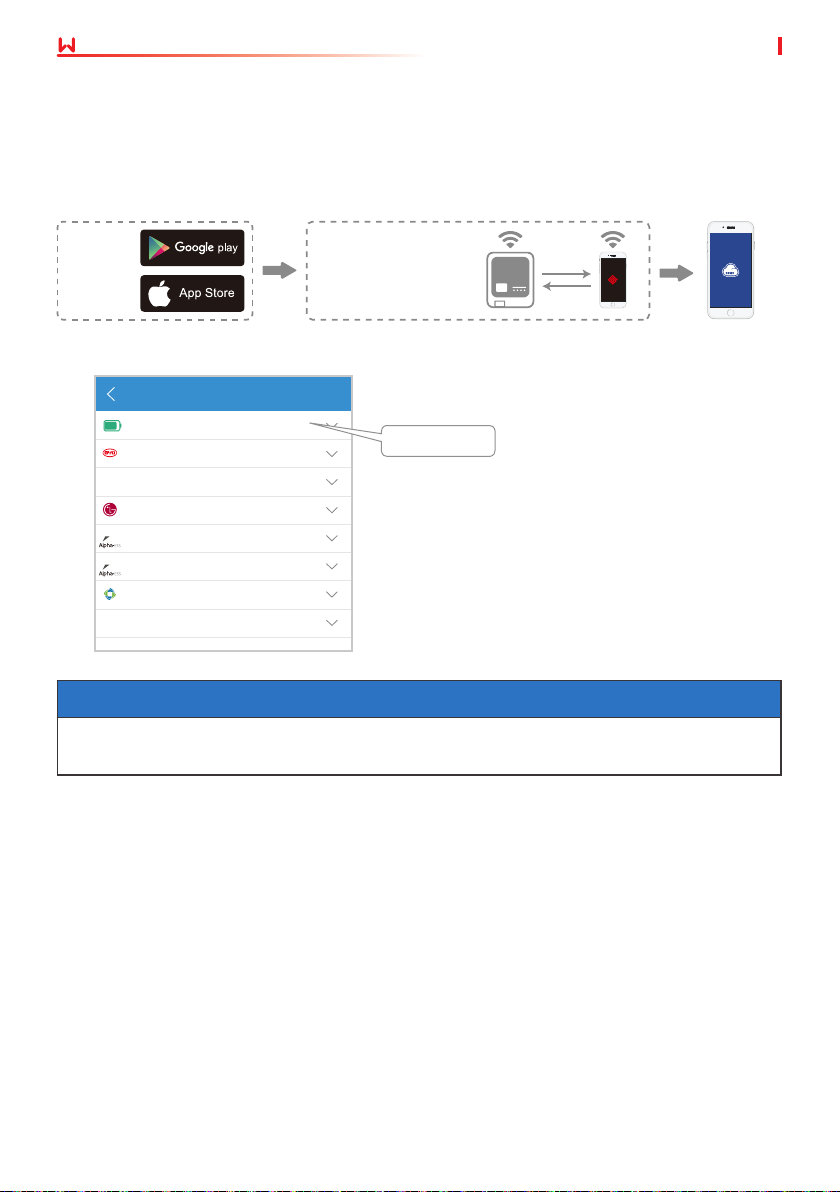
Select battery model via PV Master after successfully connecting the battery module and the
inverter.
App installation and connection
Download
and install
the PV
Master
app
Connect your smart phone
and the inverter
Wi-Fi SSID: Solar-WiFi***
Password: 12345678
Set battery model via the PV Master app.
Select Battery Model
GoodWe
BYD
PYLON
LG
AlpahESS
eSTORE
GCL
DYNESS
LX F-H
Select LX F-H.
NOTICE
"Battery Communication Failure" will be displayed if you select the wrong battery model. Please
select the right battery model accordingly.
34
Page 41
User Manual V1.6-2022-12-15
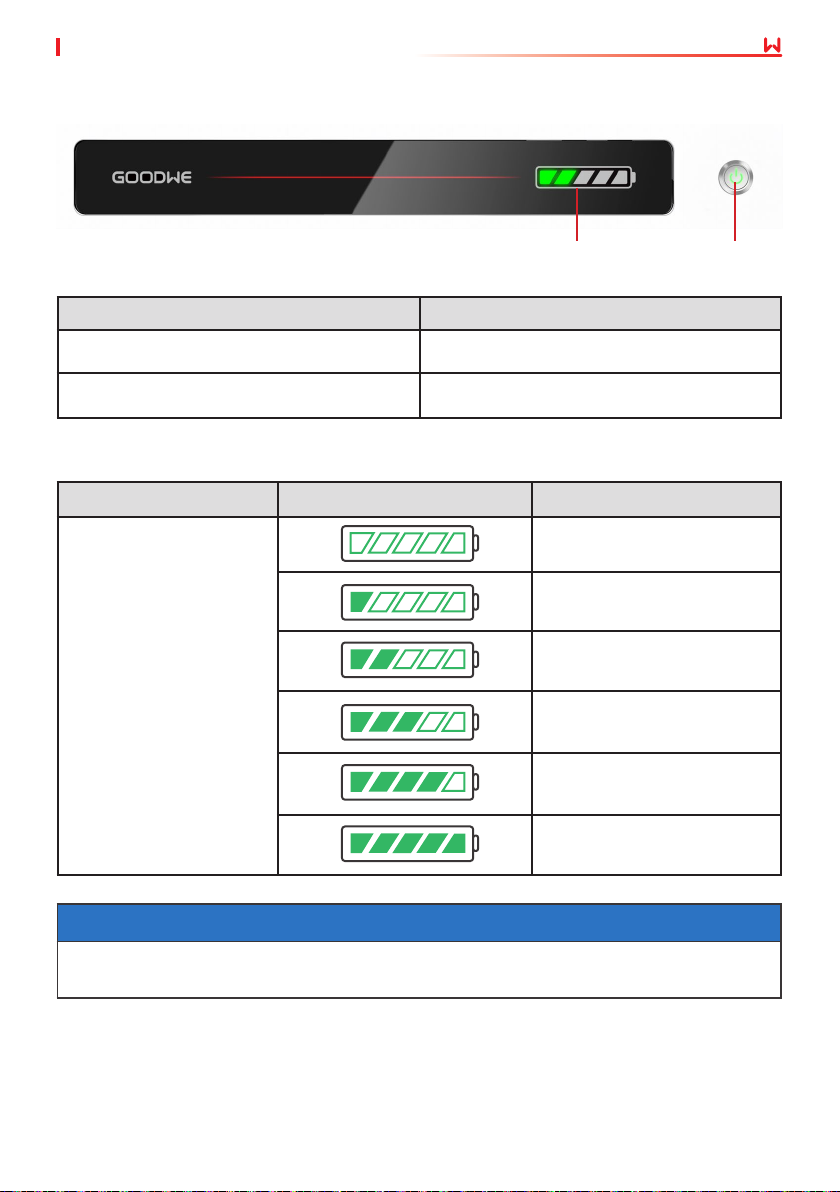
7.4 Indicator Status
07 Equipment Commissioning
SOC Indicator
Button Indicator Status
Green Standby or Working
Red Alarming or Faulty
7.4.1 Normal Status
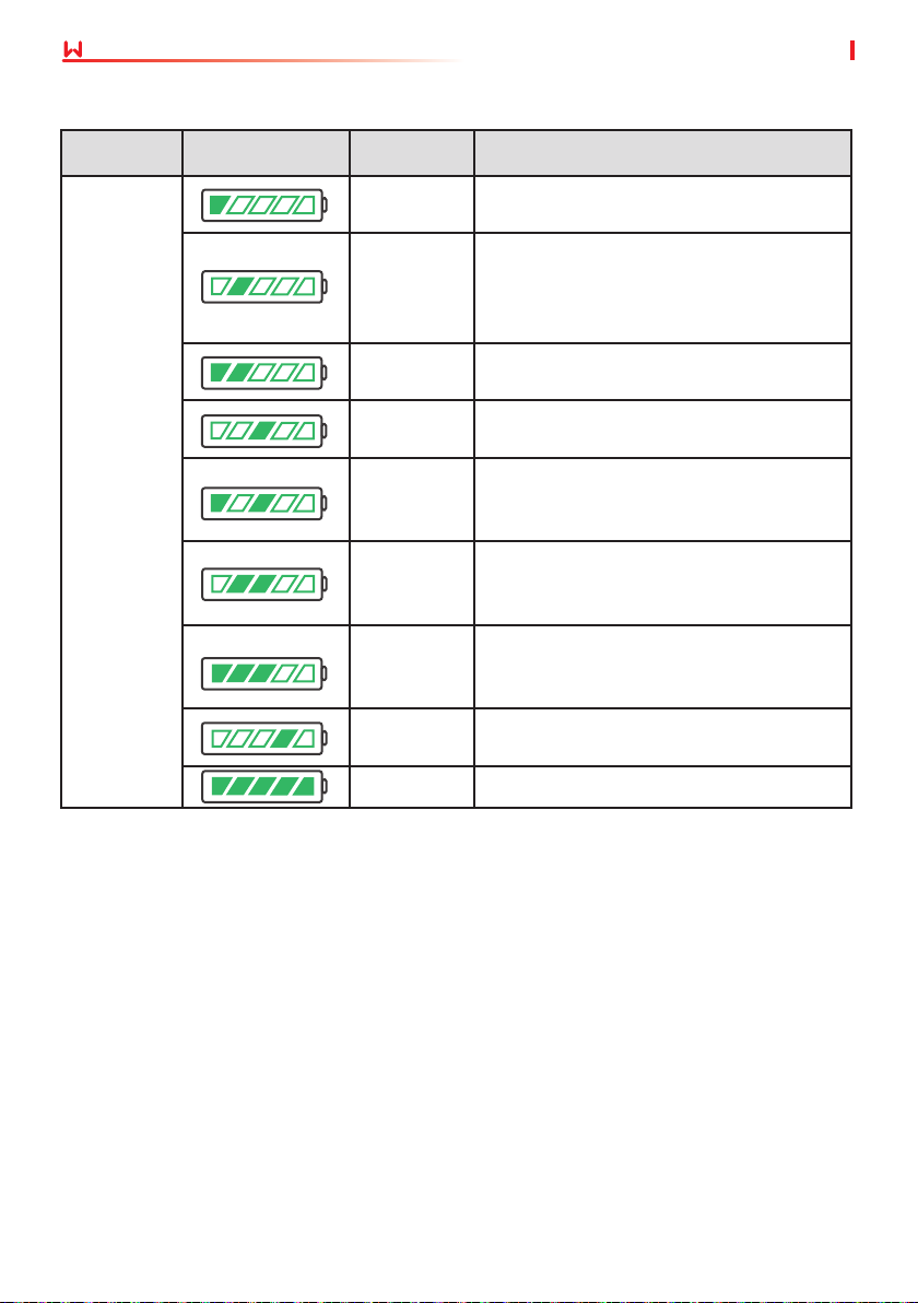
Button Indicator SOC Indicator Description
Idle: green light
double blink
Standby: green light
single blink
Working: steady green
Button Indicator
SOC<5%
5%≤SOC<25%
25%≤SOC<50%
50%≤SOC<75%
75%≤SOC<95%
NOTICE
• The SOC indicator keeps on when charging.
• The SOC indicator single blinks when discharging.
35
SOC≥95%
Page 42
07 Equipment Commissioning
7.4.2 Alarming Status
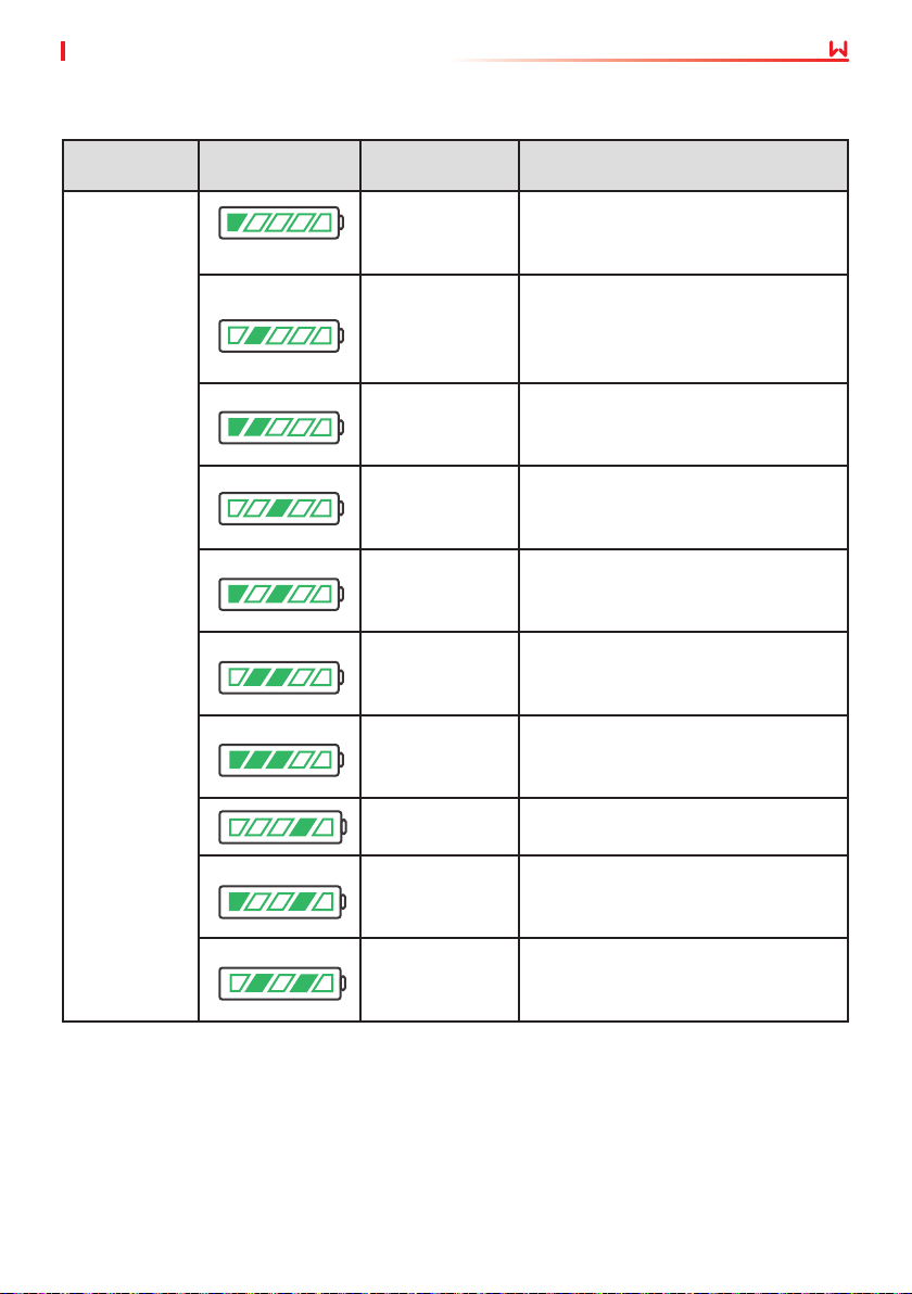
User Manual V1.6-2022-12-15
Button
Indicator
Red light
double blink
SOC Indicator Alarm Solutions
Battery
Overvoltage
Battery
Undervoltage
Overcurrent
Charging
Overcurrent
Discharging
Temperature
Dierence
Exception
High
Temperature
Low
Temperature
Interlock
Failure
Others Contact the after-sales service.
Restart the battery. If the problem persists,
please contact the after-sales service.
Long press the button for 5 seconds to start
the battery under charging conditions. If
the problem persists, contact the after-sales
service.
Restart the battery. If the problem persists,
please contact the after-sales service.
Restart the battery. If the problem persists,
please contact the after-sales service.
Power o and wait for 2 hours. If the
problem persists, please contact the after-
sales service.
Power o and wait for 2 hours. If the
problem persists, please contact the after-
sales service.
Power o and wait for 2 hours. If the
problem persists, please contact the after-
sales service.
Contact the after-sales service.
36
Page 43
User Manual V1.6-2022-12-15
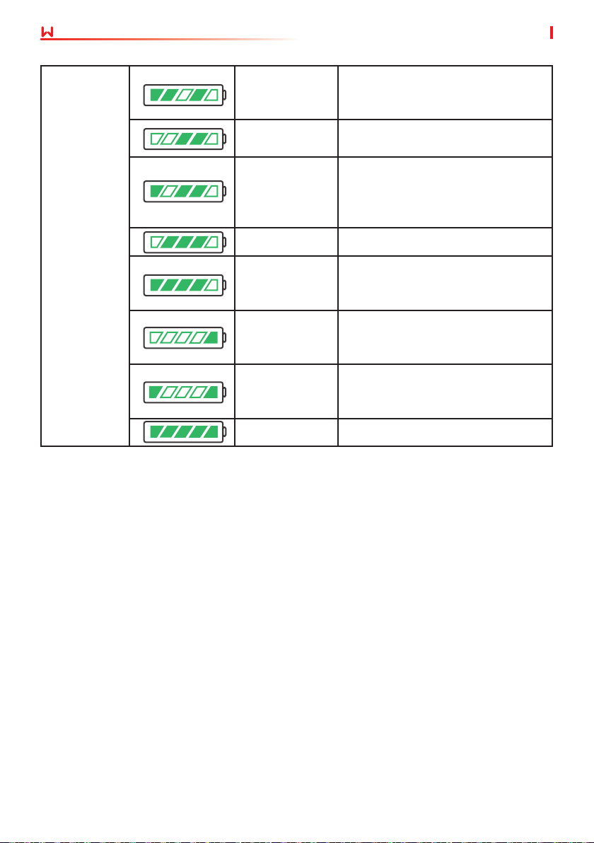
7.4.3 Faulty Status
07 Equipment Commissioning
Button
Indicator
Steady red
SOC Indicator Fault Solutions
Battery
Overvoltage
Battery
Undervoltage
Overcurrent
Charging
Overcurrent
Discharging
Temperature
Dierence
Exception
High
Temperature
Low Temperature
Inconsistent
Software Version
Precharge Fault
Relay Fault
Restart the battery. If the problem
persists, please contact the after-sales
service.
Long press the button for 5 seconds
to start the battery under charging
conditions. If the problem persists,
contact the after-sales service.
Restart the battery. If the problem
persists, please contact the after-sales
service.
Restart the battery. If the problem
persists, please contact the after-sales
service.
Power o and wait for 2 hours. If the
problem persists, please contact the
after-sales service.
Power o and wait for 2 hours. If the
problem persists, please contact the
after-sales service.
Power o and wait for 2 hours. If the
problem persists, please contact the
after-sales service.
Contact the after-sales service.
Restart the battery. If the problem
persists, please contact the after-sales
service.
Restart the battery. If the problem
persists, please contact the after-sales
service.
37
Page 44
07 Equipment Commissioning
Air Switch Fault
Insulation Fault
Internal
Communication
Fault
User Manual V1.6-2022-12-15
Restart the battery. If the problem
persists, please contact the after-sales
service.
Do not touch the batteryand contact
the after-sales service.
Power o and check the
communication cables. Restart the
battery. If the problem persists,
contact the after-sales service.
Steady red
SN Fault Contact the after-sales service.
Voltage Balance
Fault
Inconsistent
Master and Slave
Temp. Sensor
Fault
Others Contact the after-sales service.
Restart the battery. If the problem
persists, please contact the after-sales
service.
Restart the battery. If the problem
persists, please contact the after-sales
service.
Restart the battery. If the problem
persists, please contact the after-sales
service.
38
Page 45
08 MaintenanceUser Manual V1.6-2022-12-15
8 Maintenance
8.1 Power OFF the Battery System
DANGER
• Power o the battery system before operations and maintenance. Otherwise, the
equipment may be damaged or electric shocks may occur.
• Push the air switch to restart the battery.
Follow the steps below to power o the battery system to prevent the system from being
damaged.
Method one:
Step 1: Turn o the inverter in the system following the instructions in the user manual of the
inverter.
Step 2: Long press the multifunction button indicator for more than 15s, and make sure that the
SOC indicator and multifunction button indicator of the PCU are o.
Method two:
Step 1: Turn o the inverter in the system following the instructions in the user manual of the
inverter.
Step 2: Disconnect the air switch, and make sure that the SOC indicator and multifunction
button indicator of the PCU are o.
8.2 Routine Maintenance
WARNING
• Contact after-sales service for help if you nd any problems that may inuence the battery
or the hybrid inverter. Disassemble without permission is strictly forbidden.
• Contact after-sale service for help if the copper conductor is exposed. Do not touch or
disassemble privately because the high voltage danger exists.
• In case of other emergencies, contact after-sales service as soon as possible. Operate
following the instructions or wait for the after-sales service personnel.
Maintaining Item Maintaining Period
Check whether the locking brackets are secured, tighten it if not. Once every 6 months
Check whether the outer enclosure is broken. Repair the painting
or contact after-sales service if there is any broken.
Check whether there is an exposed cable. Replace the exposed
cable or contact the after-sales service for help.
Check whether there is any dust around the battery module. Clean
the dust if there is any to avoid aecting heat dissipation.
Check whether there is any liquid or pest near the battery to avoid
intrusion in a long term.
39
Once every 6 months
Once every 6 months
Once every 6 months
Once every 6 months
Page 46
09 Technical Parameters
User Manual V1.6-2022-12-15
9 Parameters
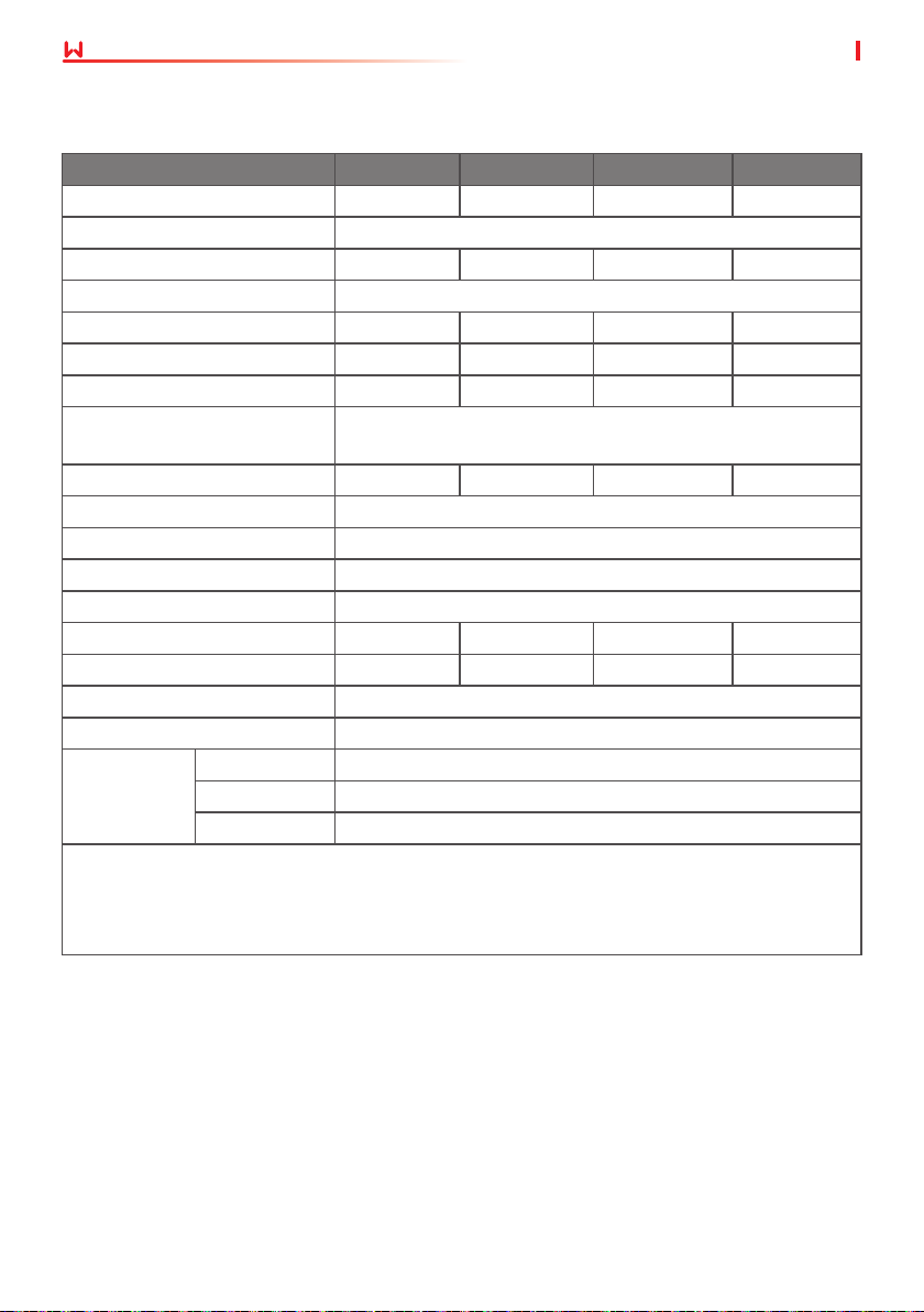
Lynx home F series
Technical Parameters LX F6.6-H LX F9.8-H LX F13.1-H LX F16.4-H
Usable Energy(kWh)*
Battery Module LX F3.3-H: 38.4V 3.27kWh
Number of Modules 2 3 4 5
Cell Type LFP(LiFePO4)
Cell Conguration 64S1P 96S1P 128S1P 160S1P
Nominal Voltage (V) 204.8 307.2 409.6 512
Operating Voltage Range (V) 182.4~230.4 273.6~345.6 364.8~460.8 456~576
Nominal Dis-/Charge Current
*2
(A)
Nominal Power (kW)
Operating Temperature (℃) Charge: 0 ~ +50; Discharge: -20 ~ +50
Relative Humidity 0~95%
Max. Operating Altitude (m) 2000
Communication CAN
Weight (kg) 115 158 201 244
Dimensions (W×H×D mm)
Enclosure Type IP55
Installation Location Grounded
Standard and
Certication
*1: Test conditions, 100% DOD, 0.2℃ charge & discharge at +25±2 °C for battery system at
beginning life. System Usable Energy may vary with dierent Inverter.
*2: Nominal Dis-/Charge Current and power derating will occur related to Temperature and
SOC.
1
6.55 9.83 13.1 16.38
25
*2
5.12 7.68 10.24 12.8
600×625×380 600×780×380 600×935×380 600×1090×380
Safety IEC62619, IEC62040, CEC
EMC CE, RCM
Transportation UN38.3
40
Page 47
User Manual V1.6-2022-12-15
09 Technical Parameters
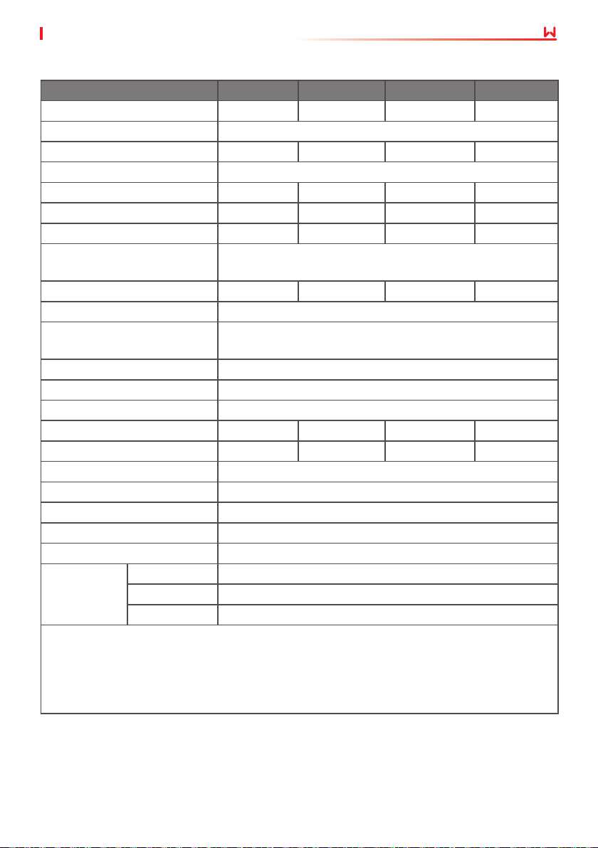
Lynx home F Plus+ series
Technical Parameters LX F6.6-H LX F9.8-H LX F13.1-H LX F16.4-H
Usable Energy(kWh)*
Battery Module LX F3.3-H: 38.4V 3.27kWh
Number of Modules 2 3 4 5
Cell Type LFP(LiFePO4)
Cell Conguration 64S1P 96S1P 128S1P 160S1P
Nominal Voltage (V) 204.8 307.2 409.6 512
Operating Voltage Range (V) 182.4~230.4 273.6~345.6 364.8~460.8 456~576
Nominal Dis-/Charge Current
*2
(A)
Nominal Power (kW)
Short-Circuit Current 2.62kA @ 1.62ms
Operating Temperature Range
(℃)
Relative Humidity 0~95%
Max. Operating Altitude (m) 2000
Communication CAN
Weight (kg) 115 158 201 244
Dimensions (W×H×D mm)
Ingress Protection Rating IP55
Storage Temperature (℃) -20 ~ +45 (≤ One Month); 0 ~ +35 (≤ One Year)
Mounting Method Grounded
Round-trip Eciency 96.40%
Cycle Life
*3
Standard and
Certication
*1: Test conditions, 100% DOD, 0.2℃ charge & discharge at +25±2 °C for battery system at
beginning life. System Usable Energy may vary with dierent Inverter.
*2: Nominal Dis-/Charge Current and power derating will occur related to Temperature and
SOC.
*3: Based on 2.5~3.65V voltage rang @25±2℃ of Cell under 1C/1C test condition and 80% EOL.
1
6.55 9.83 13.1 16.38
25
*2
5.12 7.68 10.24 12.8
Charge: 0 ~ +50; Discharge: -20 ~ +50
600×610×380 600×765×380 600×920×380 600×1075×380
≥3500 @1C/1C
Safety IEC62619, IEC 62040, VDE2510-50, CEC
EMC CE, RCM
Transportation UN38.3
41
Page 48
Ocial
Website
PV Master App
GoodWe Technologies Co.,Ltd.
No. 90 Zijin Rd., New District, Suzhou, 215011, China
www.goodwe.com
Contact Information
 Loading...