

Page 1
User Manual
Hybrid Inverter
ES Series
V1.1-2022-01-05
Page 2

Content User Manual V1.1-2022-01-05
TABLE OF CONTENTS
01 Introduction ..............................................................1
1.1 Operation Modes Introduction ................................................................1
1.2 Safety and Warning ...................................................................................2
1.3 Product Overview ......................................................................................4
02 Installation Instructions .............................................5
2.1 Unacceptable Installations .......................................................................5
2.2 Packing List ................................................................................................6
2.3 Mounting ....................................................................................................6
2.3.1 Select Mounting Location ................................................................................. 6
2.3.2 Mounting ............................................................................................................7
2.4 Electrical Wiring Connection ....................................................................9
2.4.1 PE Cable Connection .........................................................................................9
2.4.2 PV Wiring Connection .....................................................................................10
2.4.3 Battery Wiring Connection .............................................................................10
2.4.4 On-Grid&Back-up Connection ........................................................................ 12
2.4.5 Smart Meter & CT Connections ..................................................................... 15
2.5 DRED & Remote Shutdown Device Connection ...................................17
2.6 WiFi Module Connection .........................................................................18
2.7 Earth Fault Alarm Connection ................................................................18
03 MANUAL OPERATION ................................................ 21
3.1 Wi-Fi Conguration .................................................................................21
3.2 PV Master .................................................................................................22
3.3 CEI Auto-Test Function ............................................................................23
3.4 Startup/shutdown Procedure ................................................................23
3.5 SEMS Portal ..............................................................................................23
2
Page 3

ContentUser Manual V1.1-2022-01-05
04 OTHER ..................................................................... 24
4.1 Error Messages. .......................................................................................24
4.2 Troubleshooting ......................................................................................26
4.3 Disclaimer .................................................................................................30
4.4 Technical Parameters ............................................................................32
4.5 Quick Checklist To Avoid Dangerous Conditions .................................36
Appendix ..................................................................... 37
3
Page 4
01 Introduction User Manual V1.1-2022-01-05
01 Introduction
The ES series, also called hybird or bidirectional solar inverters, apply to soalr system with
partcipation of PV, battery, loads and grid system for energy management. The energy produced
by PV system shall be used to optimize household, excess power charges battery and the
rest power could be exported to the grid. Testing to AS/NZS 4777.2:2020 for multiple phase
combinations has not been conducted
The battery shall discharge to support loads when PV power is insucient to meet selfconsumption needs. If battery power is not sucient, the system will take power from the utility
grid to support loads.
The preceding introduction describes the general operation
of the ES system. The operation mode can be changed
with the PV Master app based on the system layout. The
possible operation modes for the ES system are shown
below.
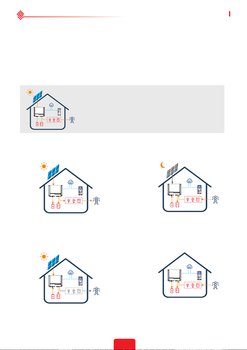
1.1 Operation Modes Introduction
ES system normally has the following operation modes based on your conguration and layout
conditions.
Mode I
The energy produced by the PV system is used
to optimize self-consumption needs. The excess
energy is used to recharge the batteries, any
remaining excess is then exported to the grid.
Mode III
When the grid fails, the system will
automatically switch to back-up mode. The
back-up loads can be supplied by both PV and
battery energy.
Mode II
When there is no PV, and the battery is
sucient, it can supply the load together
with grid power.
Mode IV
Battery could be charged by grid, and
charge time/power could be set to various
options on the PV Master App.
1
Page 5
User Manual V1.1-2022-01-05 01 Introduction
1.2 Safety and Warning
The ES series of inverters from GoodWe Technologies Co., Ltd. (also called GoodWe) strictly
complies with related safety rules for product design and testing. Please read and follow all of
the instructions and cautions appearing on the inverter or in the User Manual during installation,
operation and maintenance, as any improper operation might cause personal injury or property
damage.
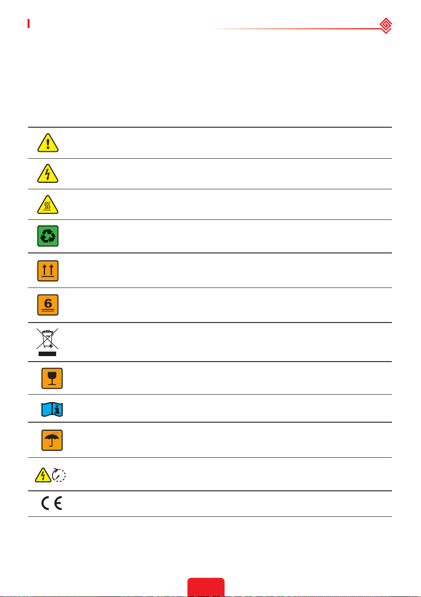
Symbol Explanation
Caution!
Failure to observe any warnings contained in this manual may result in injury.
Danger - high voltage and electric shock!
Danger - hot surface!
The components of the product can be recycled.
This side up! This package must always be transported, handled and stored in such
a way that the arrows always point upwards.
No more than six (6) identical packages being stacked on each other.
Products shall not be disposed as household waste.
Fragile - The package/product should be handled carefully and never be tipped over
or slung.
Refer to the operating instructions.
Keep dry! The package/product must be protected from excessive humidity and
must be stored under cover.
This symbol indicates that you should wait at least 5mins after disconnecting the inverter
from the utility grid and from the PV panel before touching any inner live parts.
5min
CE mark.
2
Page 6
01 Introduction User Manual V1.1-2022-01-05
Safety Warnings
Any installation or operations on the inverter must be performed by qualied electricians
in compliance with standards, wiring rules and the requirements of local grid authorities or
companies (such as AS 4777 and AS/NZS 3000 in Australia).
Before any wiring connection or electrical operation on inverter, all battery and AC power
must be disconnected from inverter for at least 5 minutes to make sure inverter is totally
isolated to avoid electric shock.
The temperature of inverter surface might exceed 60℃ during operation, so please make
sure it has cooled down before touching it, and make sure the inverter is out of reach of
children.
Do not open the inverter's cover or change any components without manufacturer's
authorization, otherwise the warranty commitment for the inverter will be invalid.
Usage and operation of the inverter must follow instructions in this user manual, otherwise
the protection design might be impared and warranty commitment for the inverter will be
invalid.
Appropriate methods must be adopted to protect inverter from static damage. Any damage
caused by static is not warranted by manufacturer.
PV negative (PV-) and battery negative (BAT-) on inverter side is not grounded as default
design. Connecting PV- to EARTH are strictly forbidden.
PV modules used on the inverter must have an IEC61730 class A rating, and the total opencircuit voltage of PV string/array is lower than the maximum rated DC input voltage of the
inverter. Any damage caused by PV over-voltage is beyond warranty.
The inverter, with built-in RCMU, will exclude possibility of DC residual current to 6mA, thus in
the system an external RCD (type A) can be used(≥30mA).
In Australia, the inverter internal switching does not maintain neutral integrity, which must
be addressed by external connection arrangements like in the system connection diagram for
Australia.
In Australia, output of back-up side in switchbox should be labeled on "Main Switch UPS
Supply".The output of normal load side in switch box should be labeled "Main Switch Inverter
Supply".
3
Page 7
User Manual V1.1-2022-01-05 01 Introduction
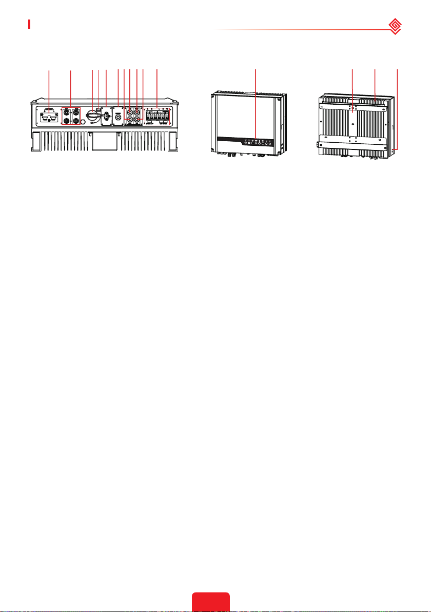
1.3 Product Overview
1210 11987654321
13
14 15
Battery Terminal
1.
(BATTERY +/-)
4. DC Switch Locking Hole 5.
DRED or Remote
7.
Shutdown
Communication Port
10. Reserved Port 11.
13. Mounting Plate 14. Heat Sink 15. PE Terminal
* Model GW3648D-ES inverters are designed without DC switch. For inverters designed with
DC switch, the model name should be GW3648C-ES.
Model GW5048D-ES inverters are designed without DC switch. For inverters designed with
DC switch, the model name should be GW5048C-ES.
If the inverter is not equipped with a DC switch, an external DC breaker shall be added. The
external DC breaker shall be AU/NZ certied; Complied to AS60947.3:2018; Be classied as
DC-PV 2; With ratings and properties suitable for the intended application conditions such as
outdoor, exposed to sunshine, on non-combustible material surface.
PV Input Terminal (PV1/
2.
PV2)
Communication Module
Port (WiFi or LAN)
BMS Communication
8.
Port
AC Terminal (ON-GRID
and BACKUP)
3. DC Switch (optional)*
METER Communication
6.
Port
RS485 Communication
9.
Port
12. Indicators
4
Page 8
01 Introduction User Manual V1.1-2022-01-05
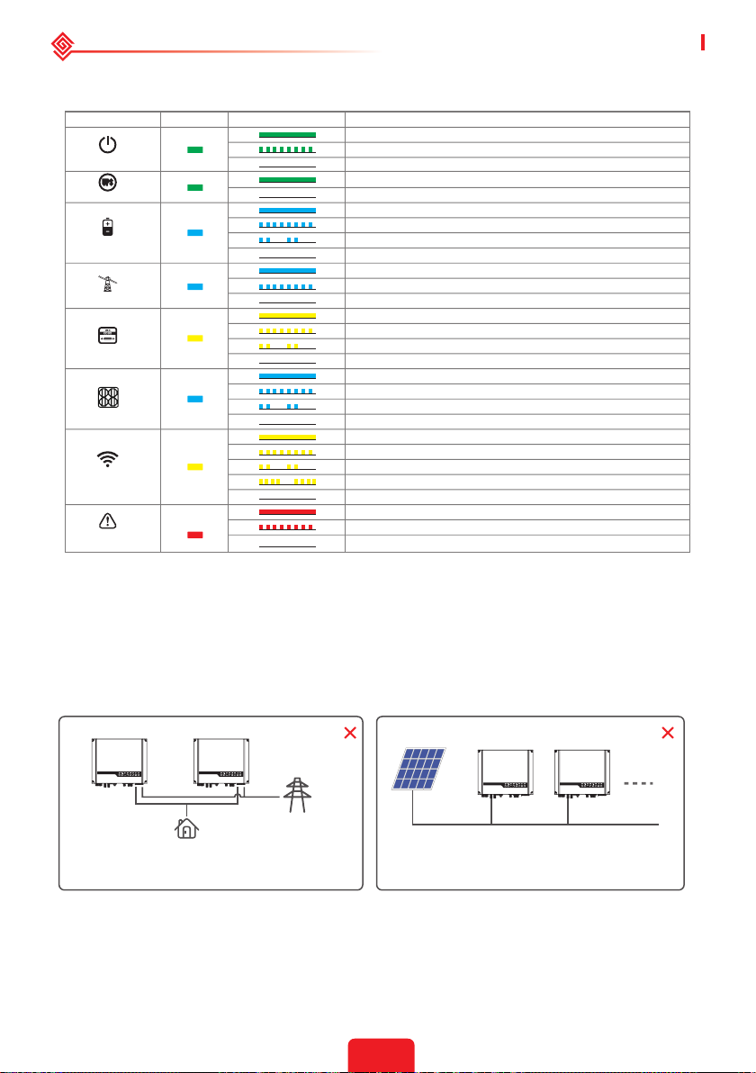
LED Indicators
INDICATOR
SYSTEM
BACK-UP
BATTERY
GRID
ENERGY
SOLAR
WiFi
FAULT
COLOR
STATUS
EXPLANATION
ON = System is ready
BLINK = System is starting up
OFF = System is not operating
ON = Back-up is ready / power available
OFF = Back-up is o / on power available
ON = Battery is charging
BLINK 1 = Battery is discharging
BLINK 2 = Battery is low / soc is low
OFF = Battery is disconnected / not active
ON = Grid is active and connected
BLINK = Grid is active but not connected
OFF = Grid is not active
ON = Consuming energy from grid / buying
BLINK 1 = Supplying energy to grid / zeroing
BLINK 2 = Supplying energy to grid / selling
OFF = Grid not connected or system not operating
ON = Solar inputs #1 and #2 are active
BLINK 1 = Solar input #1 is active /#2 is not active
BLINK 2 = Solar input #2 is active /#1 is not active
OFF = Solar input #1 and #2 are not active
ON = WiFi connected / active
BLINK 1 = WiFi system resetting
BLINK 2 = WiFi not connect to router
BLINK 4 = WiFi server problem
OFF = WiFi not active
ON = Fault has occurred
BLINK = Overload of back-up / Output / reduce load
OFF = No fault
02 Installation Instructions
2.1 Unacceptable Installations
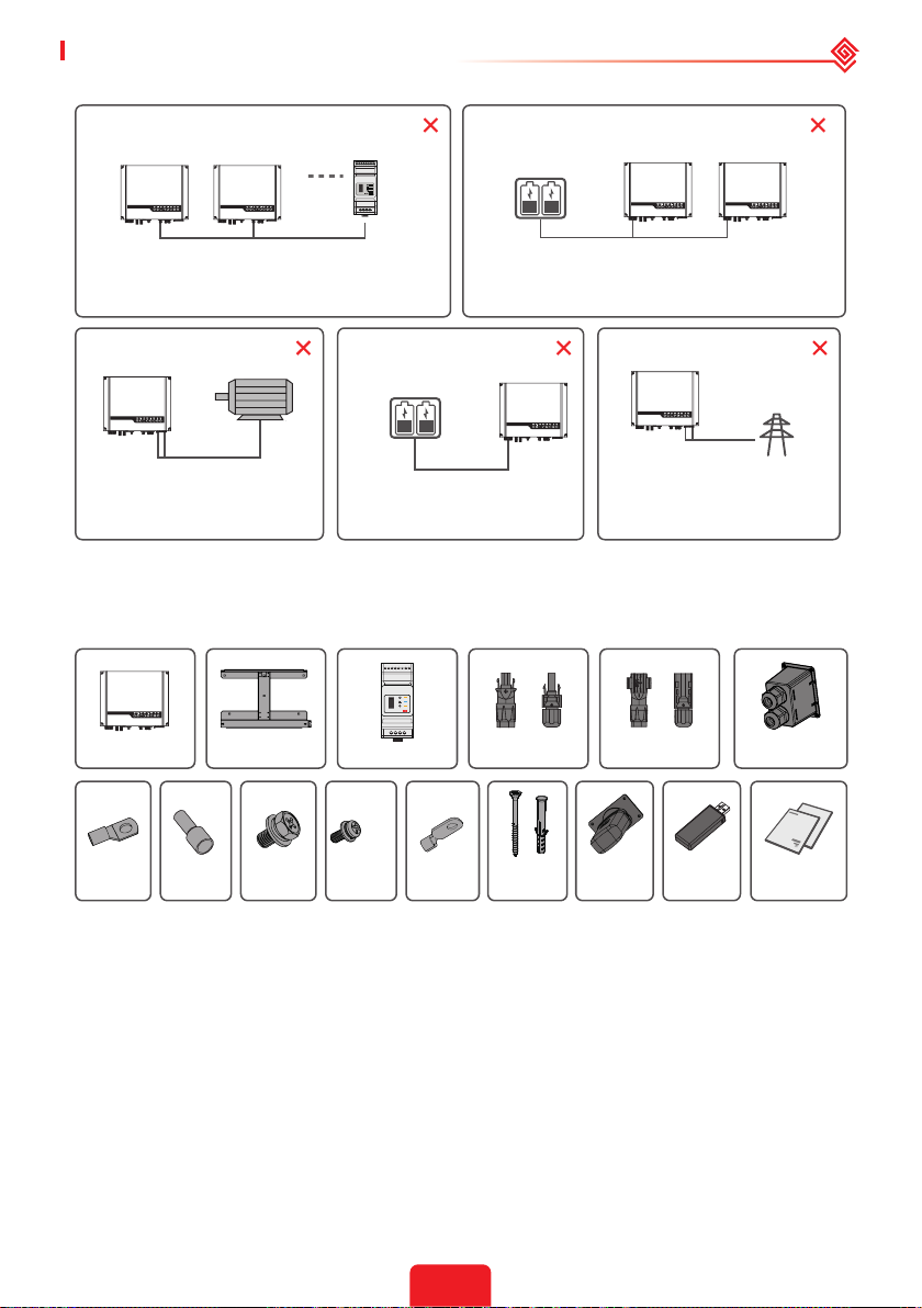
Please avoid the following installations which will damage the system or the Inverter.
The following installations should be avoided. Any damage caused will not be covered by the
warranty policy.
Back-Up Back-Up
For the general version, backup cannot connect in parallel.
For advanced applications, please contact our after-sales
department.
Load
On-Grid
Single PV string cannot connect to multiple inverters.
5
PV PV
Page 9
User Manual V1.1-2022-01-05 02 Installation Instructions
Smart Meter
One meter cannot be connected to multiple inverters.
Dierent CTs cannot connect to the same line cable.
Generator
Back-Up
The on-Grid or backup side cannot be
connected to any AC generator directly.
On-Grid
Incompatible battery
The inverter battery input must not be
connected to incompatible batteries.
Battery
One battery bank cannot be connected to multiple inverters.
Battery
Back-Up
The backup side cannot be connected
to the grid.
On-Grid
2.2 Packing List
Upon receiving the hybrid inverter, please check if any of the components as shown below are
missing or broken.
SMART METER
Wall-Mounted
Bracket
USB
Reset
Smart Meter With CT
or
Positive PV Plug
or
Negative PV PlugInverter
Battery Cover
Battery
Terminal
Pin
Terminal
Hexagon
screw
Fixed
Screw
PE
Terminal
Expansion
Bolts
WiFi
Module
Bluetooth
Module
Documentations
2.3 Mounting
2.3.1 Select Mounting Location
Mounting Support Requirements
• The mounting support shall be nonammable and reproof.
• Make sure that the support surface is solid enough to bear the product weight load.
• Do not install the product on the support with poor sound insulation to avoid the noise
generated by the working product, which may annoy the residents nearby.
For inverter's protection and convenient maintenance, mounting location for inverter should be
selected carefully based on the following rules:
Rule 1. Any part of this system shouldn't block the switch and breaker from disconnecting the
inverter from DC and AC power.
Rule 2. Inverter should be installed on a solid surface, where it is suitable for inverter's dimensions
and weight.
6
Page 10
02 Installation Instructions User Manual V1.1-2022-01-05
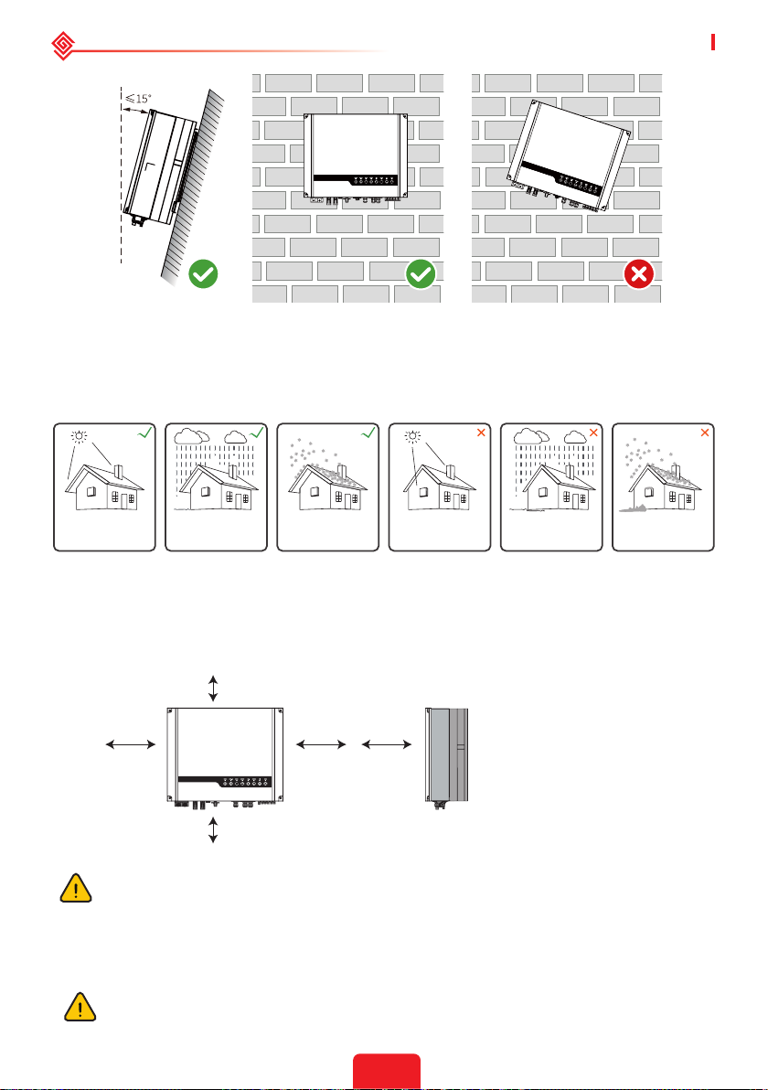
Rule 3. Inverter should be installed vertically with a max rearward tilt of 15°.
Rule 4. Ambient temperature should be lower than 45°C. The temperature and humidity at the
installation site should be within the appropriate range (60 °C for outdoor unconditioned with
solar eects).
Rule 5. It is recommanded that the installation of the inverter should be prevented from direct
sunlight, snow, rain and other negative inuences which may cause function impact or life aging.
Keep away
from sunlight
Keep dry
Keep it clear
of snow
Sun Rain
Accmulated snow
Rule 6. Inverter should be installed at eye level for convenient maintenance.
Rule 7. Product label on inverter should be clearly visible after installation. Do not damage the
lable.
Rule 8. Do not install the inverter when it is snowing or raining. If you have to, pay attention to
the waterproof and moisture-proof of the inverter and distribution box.
Rule 9. Leave enough space around the inverter according to the below gure for natural heat
dissipation.
300mm
Upward
200mm 200mm
300mm
---------- 300mm
Downward
Front
------------- 300mm
Both sides
------ 500mm
------- 200mm
500mm
If there is any radio or wireless communication equipment below 30mhz near the
inverter, make sure that:
1. Install the inverter at least 30m far away from the high-precision wireless equipment.
2. Add ferrite core with multi coil winding or low pass EMI lter to the DC cable or AC
cable.
2.3.2 Mounting
Remember that this inverter is heavy! Please be careful when lifting out from the
package.
7
Page 11
User Manual V1.1-2022-01-05 02 Installation Instructions
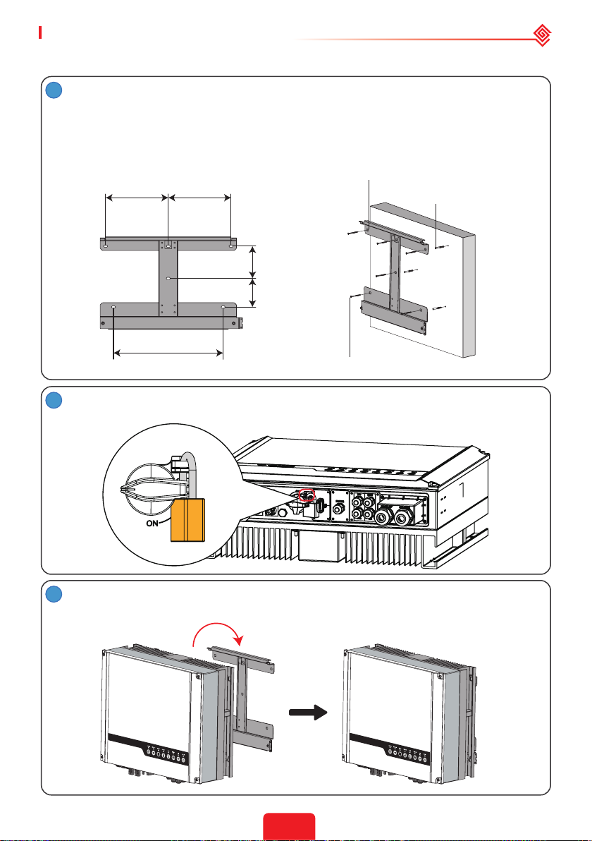
The inverter is suitable for mounting on concrete or other non-combustible surfaces only.
Please use the mounting bracket as a template to drill 4 holes in the correct positions
1
(10mm in diameter and 80mm in depth).
Use the expansion bolts in the accessory box and tightly attach the mounting bracket
to the wall.
Note: Bearing capacity of the wall must be higher than 25kg, otherwise it may not be
able to keep the inverter from dropping.
228.5mm 228.5mm
117.5mm
104.5mm
wall bracket
expansion pipe
400mm
FOR AUSTRALIA ONLY. Lock the DC switch before mounting. Unlock the DC switch
2
when you are going to switch it to power on or power o the inverter.
3
Carry the inverter by holding the heat sink on two sides and place the inverter on the
mounting bracket.
self-tapping screws
8
Page 12
02 Installation Instructions User Manual V1.1-2022-01-05
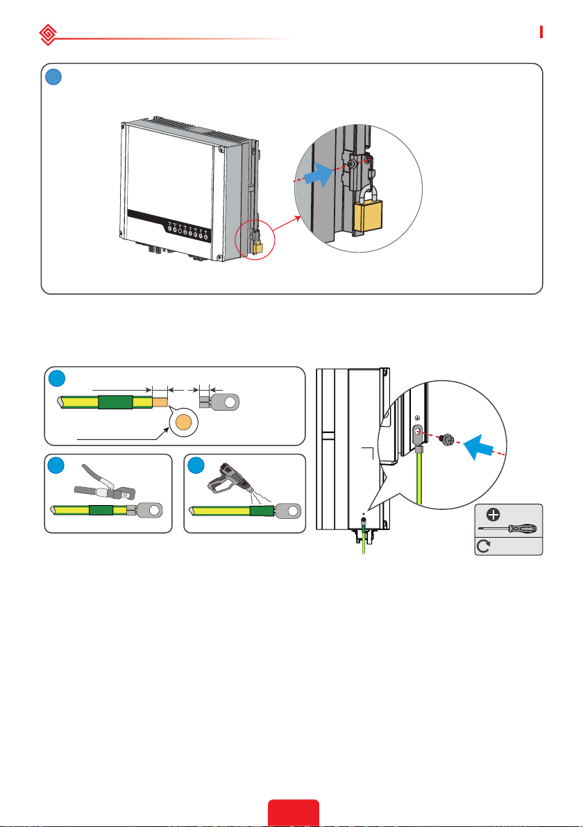
4
The inverters can be locked for anti-theft purposes if this is necessary for individual
requirements.
The lock and accessories are not included in the
package and can be purchased by the user.
2.4 Electrical Wiring Connection
2.4.1 PE Cable Connection
1
2
L=L1+(1~2)mm
Copper, ≥4mm
2
L1
3
1.5~2N·m
• Disconnect the PE cable after dismantling the equipment if needed.
• To improve the corrosion resistance of the terminal, it is recommended to apply silica gel or
paint on the ground terminal after installing the PE cable.
• The PE cable should be prepared by customers. Recommended specications:
• Type: single-core outdoor copper cable.
• Conductor cross-sectional area S≥4mm2.
M5
9
Page 13
User Manual V1.1-2022-01-05 02 Installation Instructions
3
2
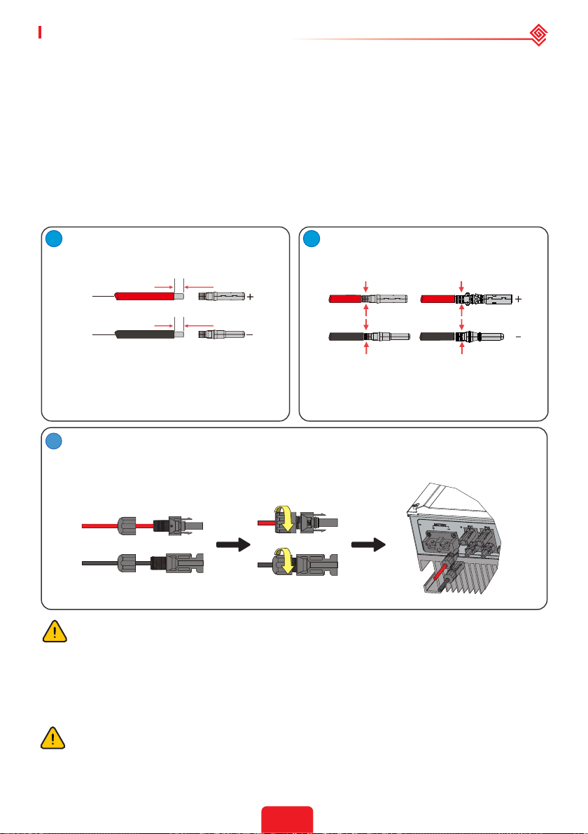
2.4.2 PV Wiring Connection
Before connecting PV panels/strings to the inverter, please make sure all requirements listed
below are followed:
• The total short-circuit current of a PV string must not exceed the inverter's max DC current.
• The minimum impedance to earth of the PV module shall be greater than R. R=Max.Input
Voltage (V)/30mA, i.e. R=1100V/30mA=36.7KΩ or R=1000V/30mA=33.4KΩ).
• The PV string must not be connected to the earth/grounding conductor.
• Use the right PV plugs in the accessory box. (BAT plugs are similar to PV plugs. Please check
before using them.)
Note: There are MC4, QC4.10, or Amphenol plugs in the accessory box. The connection details are shown
below.
1
Prepare the PV cables and PV plugs.
Connect the PV cable to the PV
connectors.
2.5-4mm
2.5-4mm
Note:
1. Please use the PV plugs and connectors from the
accessory box.
2. The PV cable should be a standard 2.5–4mm2.
2
2
7mm
7mm
MC4 /QC4.10 Series AMPHENOL Series
Note:
1. Crimp the PV cable tightly onto the connectors.
2. For Amphenol connectors, the limit buckle cannot be
pressed.
3. There will be a clicking sound if the connectors are
inserted correctly into the PV plugs.
Screw the cap on and plug it into the inverter side.
Note: There will be a clicking sound if the connectors are inserted correctly into the PV plugs.
MC
MC
The polarity of the PV strings must not be connected in a reverse manner. Otherwise, the
inverter could be damaged.
2.4.3 Battery Wiring Connection
Please be careful of any electric shock or chemical hazards.
Make sure there is an external DC breaker (≥125A) connected to the battery without build-in DC
breaker.
Make sure that the breaker is o and battery nominal voltage meets ES series'
specication before connecting battery to inverter. Make sure inverter is totally isolated
from PV and AC power.
10
Page 14
02 Installation Instructions User Manual V1.1-2022-01-05
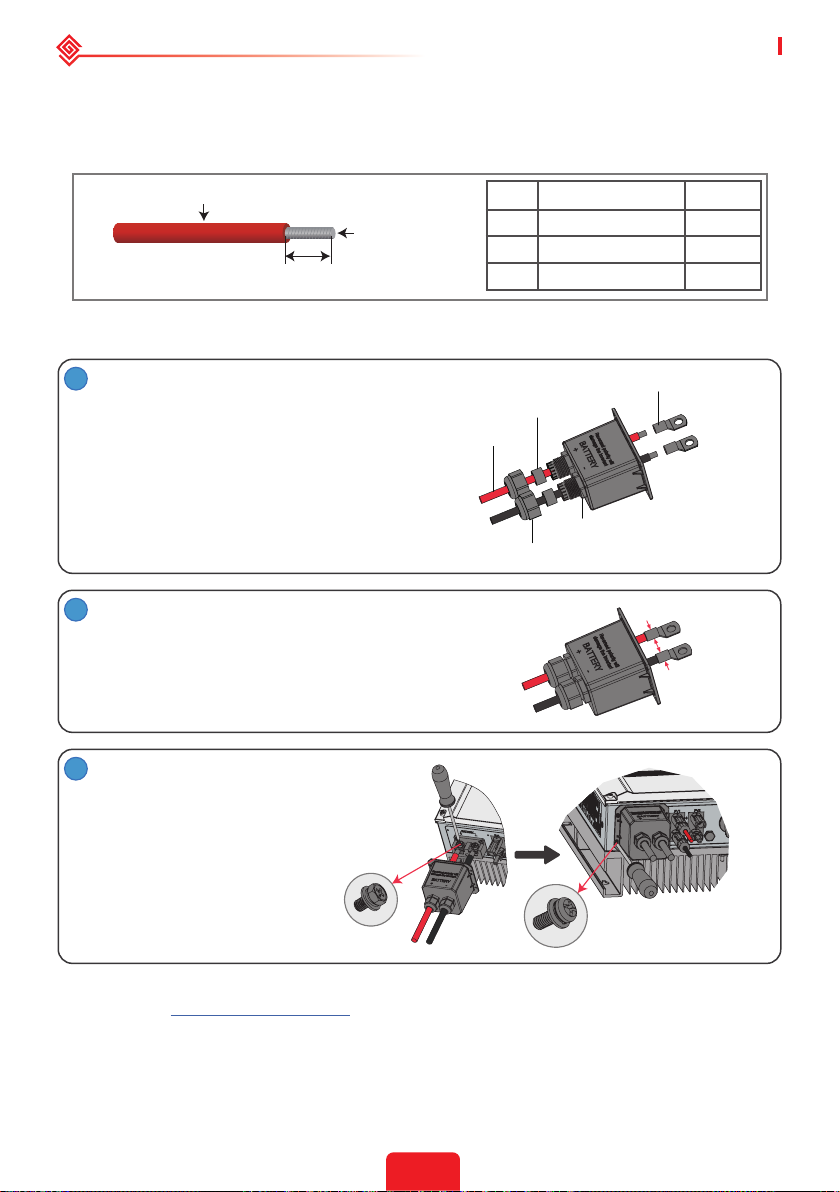
For lithium battery (pack) the capacity should be 50Ah or larger. Battery cable requirements are
as following.
You are recommended to refer to the battery user manual as well when selecting the battery
cable.
A
B
C
Battery wiring connection process
1
Prepare battery cables and accessories and
put battery power cable through battery
cover.
Note:
1. Please use accessories from accessory box.
2. Battery power cable should be 20-35mm2.
2
Make battery terminals
• Strip cable coat, revealing 10mm length of metal
core.
• Use special crimper to compress battery terminal
tightly.
3
Connect battery terminal onto inverter.
Grade Description Value
A Outside diameter Insulation 10-14mm
B Insulation section NA
C Conductor core length 20-35mm
Battery Terminal
Waterproof Ring
Cable
Insulator
Screw Cap
2
Note:
Please make sure polarity (+/-) of battery
are not reversed.
Tightening Torque: 6-8N.m
Pan Head Screw
* For the compatible lithium batteries (LG / PYLON / BYD / GCL / DYNESS / ALPHA) connection,
please refer to https://en.goodwe.com.
Battery Protection
Battery will act as a protective charge/discharge current limitation under any condition as below:
• Battery SOC is lower than I-DOD (Depth of discharge).
11
Page 15
User Manual V1.1-2022-01-05 02 Installation Instructions
• Battery voltage is lower than discharge voltage.
• Battery over heating protection.
• Battery communication is abnormal for lithium battery.
• BMS limitation for lithium battery.
When charge/discharge current limitation protection happens:
• Under on-grid mode, battery charge/discharge operation could be abnormal.
• Under o-grid mode, Back-Up supply will shut down.
Note:
• Under o-grid mode, if Back-Up supply shuts o because of battery, low battery SOC or voltage, PV
power will all be used to charge battery till battery SOC reaches 40% +(1-DOD)/2, then Back-Up supply
will be activated.
• Under on-grid mode & o-grid mode, battery is protected from over discharge by DOD and discharge
voltage.
• The DOD setting of a battery prevents the inverter from discharging battery reserve power. As soon
as the DOD is reached the load of building will only be supported by either PV power or the grid. If
there are continuous days when little or no battery charging occurs, the battery may continue to self-
consume energy to support communications with the inverter. This behavior is dierent between battery
manufactures products, however, if the SOC of the battery reaches a certain level, the inverter will boost
the SOC back up. This protection mechanism safeguards the battery from falling to 0% SOC.
2.4.4 On-Grid&Back-up Connection
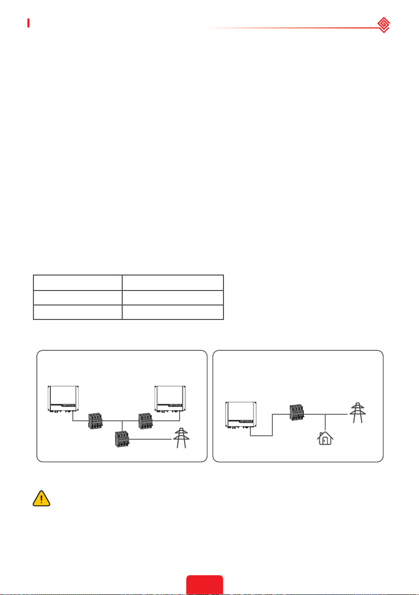
An external AC breaker is needed for on-grid connection to isolate the inverter from the utility
grid when necessary.
The requirements for the on-grid AC breaker are shown below.
Inverter Model AC Breaker Specication
GW3648D-ES 32A / 230V (e.g. DZ47-60 C32)
GW5048D-ES 40A / 230V (e.g. DZ47-60 C40)
Note: The absence of AC breaker will lead to inverter damage if an electrical short circuit happens on
grid side.
1. Use separate AC breakers for individual
inverters.
2. On the AC side, an individual breaker
should be connected between the inverter
and grid but before any loads.
AC breaker
AC breaker
AC breaker
Grid
AC breaker
Grid
Load
Requirement of AC cable connected to On-Grid and Back-Up side.
Make sure the inverter is totally isolated from any DC or AC power before connecting the
AC cable.
Note:
1. Neutral cable shall be blue, line cable shall be black or brown (preferred) and protective earth cable
shall be yellow-green.
2. For AC cables, PE cable shall be longer than N&L cables, so in case that the AC cable slips or is taken
out, the protecting earth conductor will be the last to take the strain.
12
Page 16
02 Installation Instructions User Manual V1.1-2022-01-05
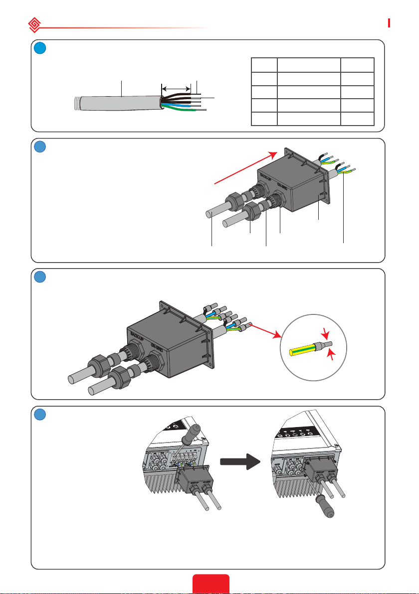
1
Prepare the terminals and AC cables according to the correct table.
A
2
Put AC cable through terminal cover as
C
B
D
Grade Description Value
A Outside diameter 13-18 mm
B Separated wire length 20-25 mm
C Conductor wire length 7-9 mm
D Conductor core section 4-6 mm
shown in the gure.
Note: Please use the terminals in accessory
box.
AC Cover
Insulator
Connection
Terminal
Cable
3
Press the 6 connectors on cable conductor core tightly.
Screw Cap
Single Hole Seal Ring
Note: Make sure cable jacket is not locked within the connector.
2
4
Tightening torque
2.0-2.5N·m
1. Connect the assembled AC cables into AC terminals with fastening torque about 2.0-
2.5N·m.
Note: Connect back-up terminals before connecting on-grid terminals. Make sure it is not connected
to a wrong side.
2. Lock the cover and screw the cap.
13
Page 17
User Manual V1.1-2022-01-05 02 Installation Instructions
Special adjustable settings
The inverter has a eld where the user could set functions, such as trip points, trip time, time
of reconnection, active and invalid of QU curve and PU curve etc. by special rmware. Please
contact after-sales for the special rmware and adjustable methods.
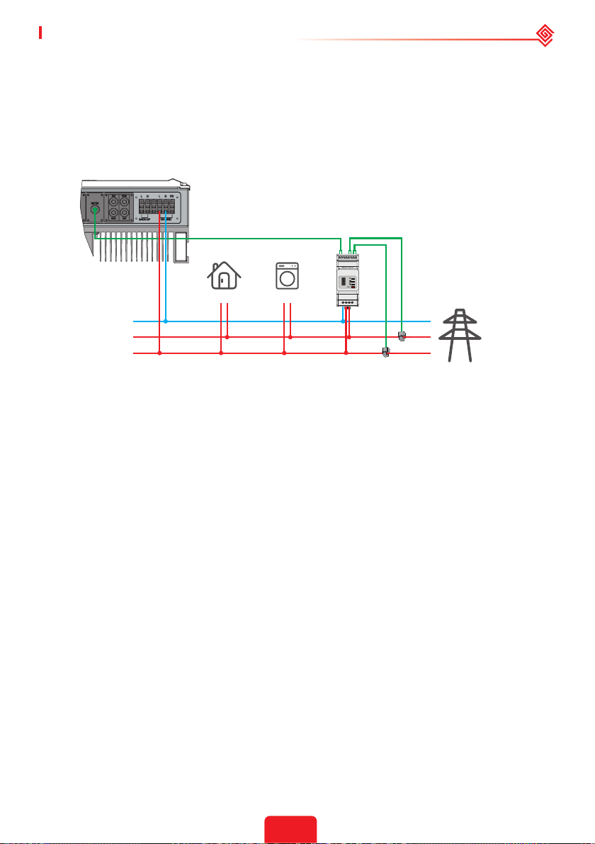
Connection For SPLIT Grid System
In SPLIT grid system, there is a solution to allow inverter to work under on-grid condition. For
details, please check the ocial application plan on website -GoodWe Hybrid Solution For Split
Grid Type.
To Smart Meter
220V Load
N
L2
L1
110V Load
CT A
CT B
Grid
Declarations For The Backup Function
The back-up output of ES hybrid inverters have over load ability.
For details please refer to the technical parameters of ES series inverter section (Page 31).
And the inverter has self-protection derating at high ambient temperature.
The below statement lays out general policies governing the energy storage inverters of the
series EH, EM, ES, ET, BH, BT and SBP.
1. For Hybrid inverters (Series EH, EM, ES and ET), the standard PV installation typically consists
of the connection of the inverter with both panels and batteries. In the case where the
system is not connected to the batteries, the back-up function is strongly not advised for use.
Manufacturer shall not cover the standard warranty and be liable for any consequences arising
from users not following this instruction.
2. Under normal circumstances, the back-up switching time is less than 10 ms (the minimal
condition to be considered as the UPS level). However, some external factors may cause the
system failing on back-up mode. As such, we recommend the users to be aware of conditions
and follow the instructions as below:
• Do not connect loads when they are dependent on a stable energy supply for a reliable
operation.
• Do not connect the loads which may in total exceed the maximum back-up capacity.
• Try to avoid those loads which may create very high start-up current surges such as inverter
air-conditioner, high-power pump etc.
• Due to the condition of the battery itself, battery current might be limited by some factors
including but not limited to the temperature, weather etc.
Acceptable Loads Are As Below:
ES series inverter is able to supply a continuous 4600VA output or maintain a 6900VA output
for less than 10 seconds on back-up side to support loads. The inverter also has self-protection
against derating at high ambient temperature.
• Inductive Load: Maximum 1.5KVA for single inductive load, maximum 2.5KVA for total
inductive load power.
• Capacitive Load: Total capacitive load (like computer, switch power etc.)power ≤3.0KVA.
(Any load with high inrush current at start-up is not accepted)
14
Page 18
02 Installation Instructions User Manual V1.1-2022-01-05
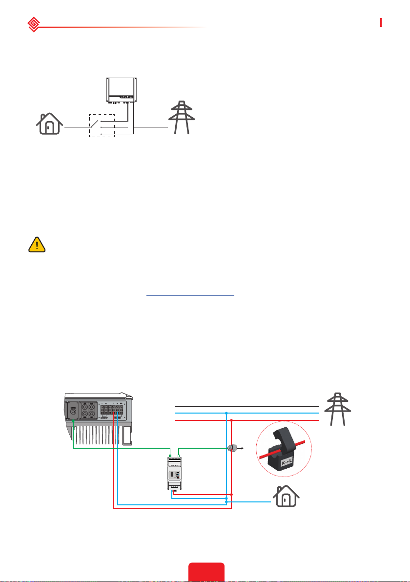
Note:
For convenient maintenance, please install a SP3T switch on back-up and on-grid side. Then it is
adjustable to support load by back-up or by grid or default settings.
1. Back-up load is supplied from back-up side.
2. Back-up load is isolated.
3. Back-up load is supplied from grid side.
Load
Back-Up
1
2
3
SP3T
On-Grid
Grid
Declarations For Backup Overload Protection
Inverter will restart itself if overload protection triggers. The preparation time for restarting will
be longer and longer (one hour at most) if overload protection repeats. Take following steps to
restart inverter immediately.
Decrease back-up load power within maximum limitation.
On The PV Master App > Advanced Settings > Click "Reset Backup Overload History".
2.4.5 Smart Meter & CT Connections
Make sure the AC cable is totally isolated from AC power before connecting the Smart
Meter and CT.
A Smart Meter with the CT in product box is compulsory for ES system installation. It can be
used to detect the grid voltages and current directions, provide the operating condition of the ES
inverter via RS485 communications. For more detailed information of the Smart Meter, refer to
the Smart Meter user manual in https://en.goodwe.com.
Note:
1. The Smart Meter with CT is already congured ; please do not change any settings on the Smart
Meter.
2. One Smart Meter can be used with only one ES inverter.
3. Three CTs must be used for one Smart Meter and must be connected on the same phase with the
Smart Meter power cable.
Smart Meter & CT connection diagram
• For Single Phase Grid
• For Three Phase Grid
To Smart Meter
PE
N
L
GM1000
15
CT
Grid
Grid side
Load
Page 19
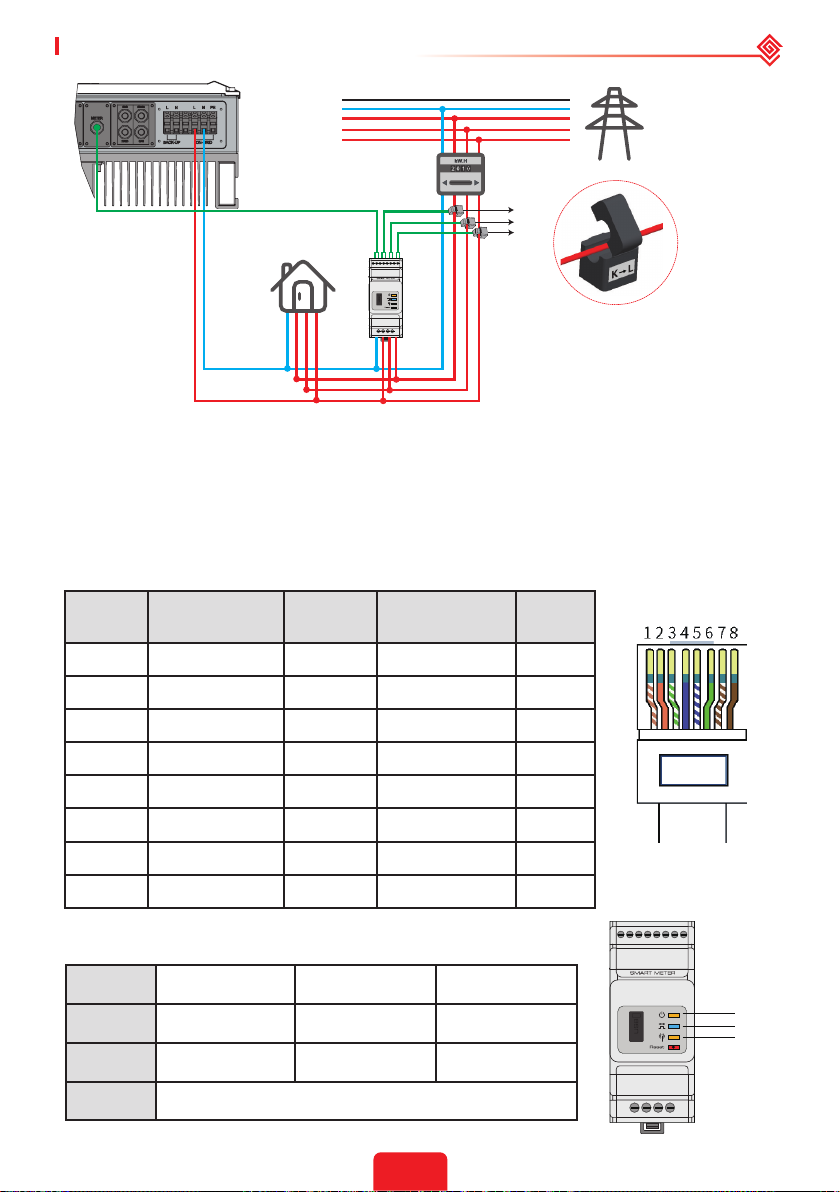
User Manual V1.1-2022-01-05 02 Installation Instructions
PE
N
L3
L2
L1
Grid
CT A connect to L1
CT B connect to L2
Grid side
CT C connect to L3
To Smart Meter
Power Meter
GM3000
CT C
CT B
CT A
Load
Note:
1. Please use the Smart Meter with 3 CTs in product box.
2. CT cable is 3m as default, could be extended to maximum of 5m.
3. Smart Meter communication cable (RJ45) is attached on the inverter ("To Smart Meter" cable), could
be extended to max 100m, and must use standard RJ45 cable and plug, as below:
Detailed PIN Functions Of Each Port On The Inverter
BMS: CAN communication is congured by default. If 485 communication is used, please contact
the after-sales service to replace this with the correct communication cable.
Position Color
BMS
Function
Smart Meter
Function
EMS
1 Orange & white 485_A2 NC 485_A
2 Orange NC NC 485_B
3 Green & white 485_B2 485_B1 485_A
4 Blue CAN_H NC NC
5 Blue & white CAN_L NC NC
6 Green NC 485_A1 485_B
7 Brown & white NC 485_B1 NC
8 Brown NC 485_A1 NC
Smart Meter LED Indications
STATUS OFF ON Blinking
POWER Not working Working /
ENERGY / Importing Exporting
COM Single blink when data are transferred to the inverter
16
POWER
ENERGY
COM
Page 20
02 Installation Instructions User Manual V1.1-2022-01-05
123456
2
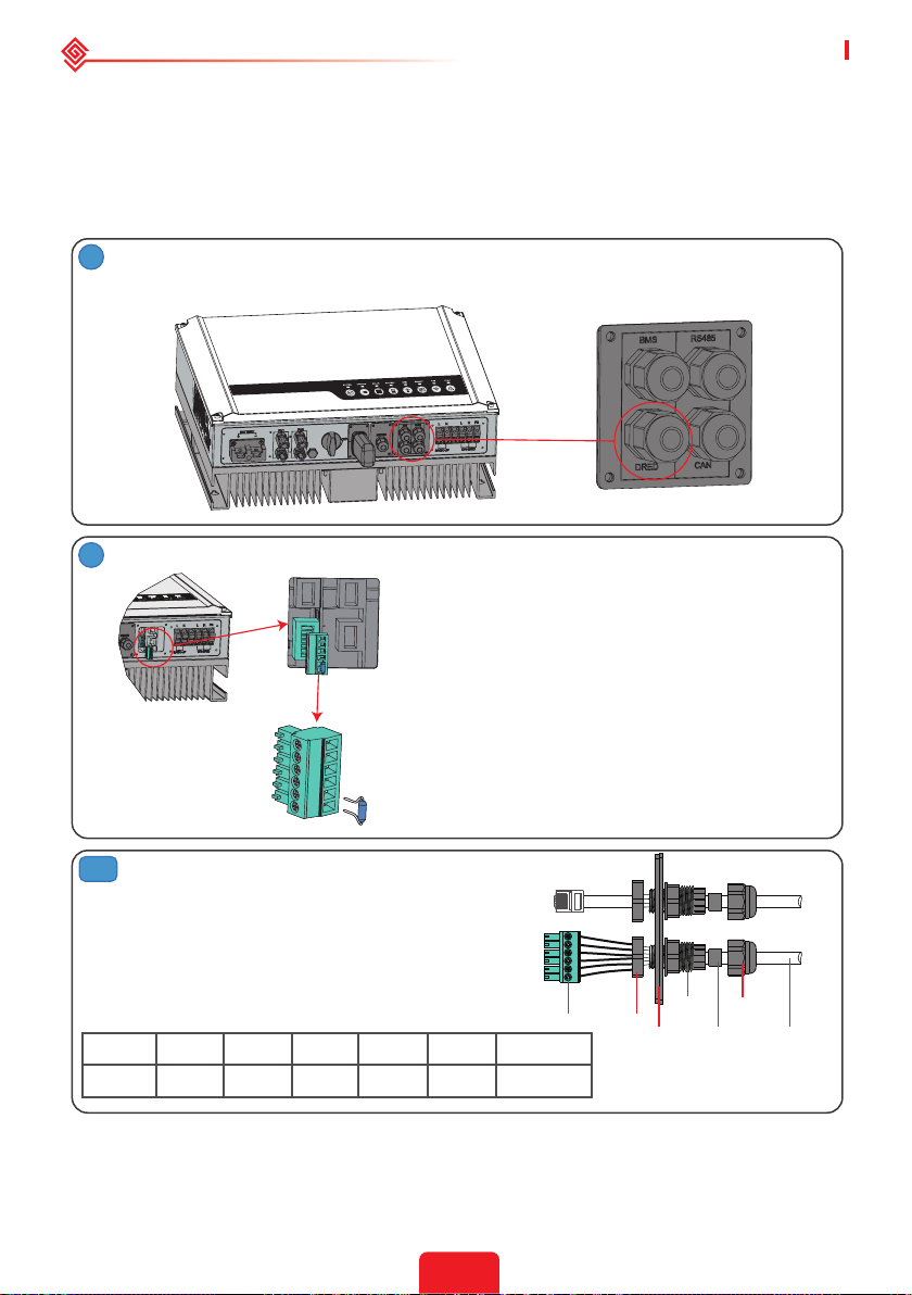
2.5 DRED & Remote Shutdown Device Connection
DRED (Demand response enabling device) is used for Australia and New Zealand installation
(also used as remote shutdown function in European countries), in compliance with Australia
and New Zealand safety requirements (or European countries). Inverter integrates control logic
and provides an interface for DRED. The DRED is not provided by inverter manufacturer.
Detailed connection of DRED & Remote Shutdown are shown below.
1
Screw this plate o from the inverter.
Note: DRED should be connected through "DRED Port" as the gure shows.
1. Plug out the 6-pin terminal and dismantle
the resistor on it.
2. Plug the resistor out, leave the 6-pin
terminal for next step.
Note: The 6-pin terminal in the inverter has the
same function as DRED. Please leave it in the
inverter if no external device is connected.
3-1
For DRED
1. Put DRED cable through the plate.
2. Connect DRED cable on the 6-pin
terminal.
The function of each connection position
as below.
NO 1 2 3 4 5 6
Function DRM1/5 DRM2/6 DRM3/7 DRM4/8 REFGEN COM /DRMO
17
Screw
Insulator
Nut
RS485
communication
board
Screw Cap
Single hole
seal ring
Cable
Page 21
User Manual V1.1-2022-01-05 02 Installation Instructions
123456
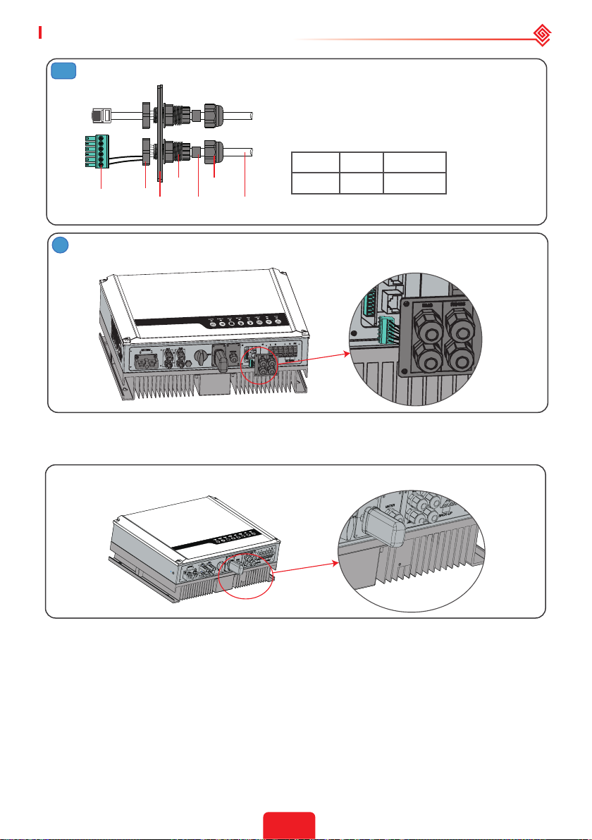
3-2
For Remote Shutdown
1. Put the cable through the plate.
2. Connect cable on the 6-pin terminal.(Wiring
from the No. 5 and 6 holes respectively.)
The function of each connection position as
below.
NO 5 6
Screw Cap
Insulator
Screw
4
Connect DRED terminal to the right position onto the inverter.
Nut
RS485
communication
board
Single hole
seal ring
Cable
Function REFGEN COM /DRMO
2.6 WiFi Module Connection
The Wi-Fi communication function is only applied to WiFi Module.
Insert the 5-Pin terminal to WiFi module.
WiFi module
2.7 Earth Fault Alarm Connection
The inverter complies with IEC 62109-2 13.9. Fault indicator LED on inverter cover will light up
and the system will email the fault information to customer. It must be installed in a high trac
area where the LED would be noticed.
Inverter should be installed at eye level for convenient maintenance.
18
Page 22
02 Installation Instructions User Manual V1.1-2022-01-05
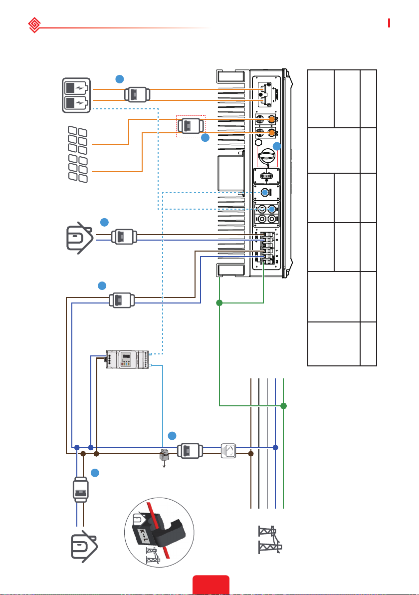
Wiring System For The Hybrid Inverter
Note: This diagram indicates the wiring structure of the hybrid inverter, not the electric wiring standard.
GW3648D-ES
1
Battery
DC Breaker
GW5048D-ES
Inverter
Please select the breaker according to the specications below:
PV
BACK-UP Loads
AC Breaker
2
AC Breaker
3
To Battery
To Smart Meter
5
6
DC Breaker
AC Breaker
125A/60V
6
Breaker
DC
AC breaker
32A/230V
AC breaker
20A/230V
household
loads
Breaker
AC breaker
25A/230V
AC breaker
16A/230V
Depends
on
30A/600V
① ② ③ ④⑤ ⑥
DC
1. For batteries with attached breaker, the external
DC breaker could be omitted.
2. Only for lithium battery which has BMS
communication.
3. Direction of the CT cannot be connected in
reverse, please follow "House→Grid" direction to do
the connection.
Power
Meter
Loads
4
AC Breaker
CT
PE
N
L3
L2
L1
Grid
19
Page 23
User Manual V1.1-2022-01-05 02 Installation Instructions
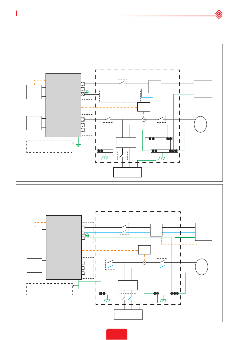
System Connection Diagrams
Note: According to Australian safety requirements, the neutral cables of the on-grid side and backup
side must be connected together. Otherwise, the backup function will not work.
This diagram is an example for an application that neutral connects with the PE in a
distribution box.
For countries such as Australia, New Zealand, South Africa, etc., please follow local wiring
regulations!
BMS
Battery
Hybrid Inverter
Solar
Array
Grounding screw hole in
the lower right corner.
L
N
Back-Up
Meter
L
N
PE
On-Grid
Do not connect this terminal
when the neutral wire and PE
wire are connected together.
E-BAR
Distribution box
RS485
RCD
LN PE
Normal Loads
Smart
Meter
CT
RCD
N-BAR
E-BAR
E-N
Link
PE
PE
L
N
L
N
Backup
Loads
Grid
This diagram is an example for grid systems without special requirements on
electrical wiring connection.
NOTE: The back-up PE line and earthing bar must be grounded properly and eectively.
Otherwise the back-up function may be abnormal when the grid fails.
BMS
Battery
Hybrid Inverter
Solar
Array
Grounding screw hole in
the lower right corner.
L
N
Back-Up
Meter
L
N
PE
On-Grid
Distribution box
RS485
RCD
LN PE
Normal Loads
Smart
Meter
L
RCD
N
PE
CT
L
N
PE
E-BARE-BAR
20
Backup
Loads
*
Grid
Page 24
02 Installation Instructions User Manual V1.1-2022-01-05
2
3
03 MANUAL OPERATION
3.1 Wi-Fi Conguration
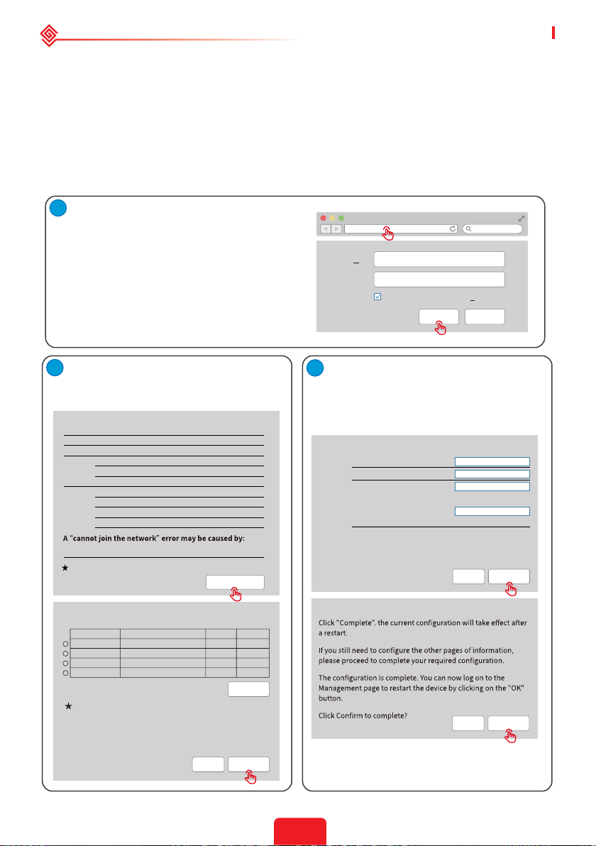
This part shows the conguration using a web page.
Wi-Fi conguration is absolutely necessary for online monitoring and maintenance.
Preparation:
1. The inverter must be powered up with battery or grid power.
2. A router with internet access to the website www.semsportal.com is required.
1
1. Connect Solar-Wi-Fi* to your PC or
smart phone (* its name is the last 8
characters of the inverter's serial number);
Password:12345678.
2. Open your browser and logon to
10.10.100.253 Admin (User): admin; Password:
admin.
3. Then click "OK".
10.10.100.253
Admin(U
Password:
):
admin
admin
Remember the password (R)
CancelOK
1. Click "Start Setup" to choose your router.
2. Then click "Next".
Device information
Firmware version
MAC address
Wireless AP mode
SSID
IP address
Wireless STA mode
Router SSID
Encryption method
Encryption algorithm
Router Password
No router, weak Wi-Fi signal, or the password is not correct
Help: The wizard will help you to complete setup
within one minute.
1.6.9.3.38.2.1.38
60:C5:A8:60:33:E1
Enable
Solar-Wi-Fi
10.10.100.253
Disable
WiFi_Bum-in
WAP/WAP2-PSK
AES
WiFi_Bum-in
Start Setup
Please select your current wireless network
SSID
Wi-Fi_Burn-in
Wi-Fi_Burn-in
Wi-Fi_Burn-in
Wi-Fi_Burn-in2
Help: When the RSSI of the selected Wi-Fi network is below
15%, the connection may be unstable. Please select another
available network or decrease the distance between the
device and router. If your wireless router does not broadcast
its SSID, please click "Next" and manually add the wireless
network.
AUTH/ENCRY
WPAPSKWPA2PSK/TKIPAES
WPAPSKWPA2PSK/TKIPAES
WPAPSKWPA2PSK/TKIPAES
WPAPSKWPA2PSK/TKIPAES
RSSI
Channel
66
100
70
72
Refresh
Back Next
1
1
1
1
1. Fill in the password of the router, then
click "Next".
2. Click "Complete".
Add the wireless network manually
Network name (SSID)
Encryption method
Encryption algorithm
Please enter the wireless network password:
Password (8-63 characters)
Note: The SSID and password are case sensitive. Please make
sure all parameters of the wireless network match those of the
router, including the password.
Save success!
Wi-Fi-Test
WPA/WPA2-PSK
AES
Router password
Show psk
Back Next
Back Complete
21
Page 25
User Manual V1.1-2022-01-05 02 Installation Instructions
Note:
1. Please make sure the password and encryption method/algorithm are the same as those of the
router.
2. If everything went well, the WiFi indicator on the inverter will change from a double blink to 4 blink
and then to a steady status, which means that the WiFi has successfully connected to the server.
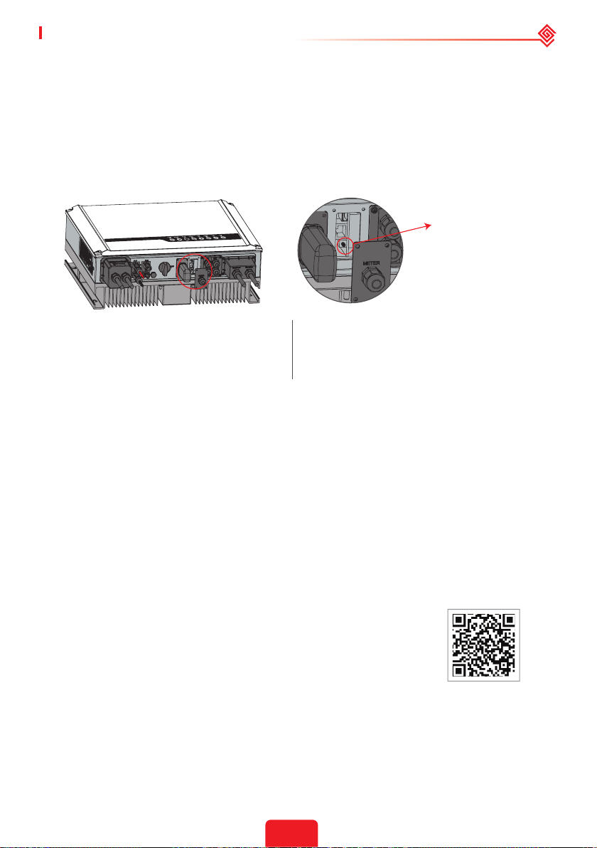
WiFi Reset & Reload
WiFi reset means restarting the WiFi module. The WiFi settings will automatically be reprocessed
and saved. WiFi Reload means setting the WiFi module to the default factory settings.
WiFi Reload Button
WiFi reset
Short press the reset button.
The WiFi LED will blink for a few seconds.
Note:
Wi-Fi reset & reload function is only used when:
1. Wi-Fi loses connection to internet or cannot connect to PV Master App successfully.
2. Cannot nd "Solar-WiFi signal" or have other Wi-Fi conguration problems.
3. Please do not use this button if Wi-Fi monitoring works well.
4.If you need to replace the module, please use the unlock tool.
WiFi reload
Long press the reset button more than 3s.
The WiFi indicator will double blink until
the WiFi is congured again.
3.2 PV Master
PV Master is an external monitoring and conguration application for hybrid inverters and is
used on smart phones or tablets for both Andriod and iOS systems. The main functions are
listed as below:
1. Congure the system to customize functions by the user.
2. Monitor and check the performance of the hybrid system.
3. Access and change the regional settings.
4. Check the inverter rmware version.
5. Set export power limit.
Search PV Master in Google Play or Apple App Store, or scan the QR
code to download the app.
Operation steps are the same for Android system and iOS system
although the two interfaces are slightly dierent.
For more detailed opertaion instructions, please refer to PV Master
user manual in www.goodwe.com.
Note:
For Australian customers please select from Australia Region A/B/C to comply with AS/NZS 4777.2:2020.
Contact local grid operator to see which Region to select. After setting the safety region, some
parameters in the inverter system will take eect according to the corresponding safety regulations, such
as PU curve, QU curve, trip protection, etc. For Australian and European users, if you need to change the
conguration parameters, please refer to the PV Master user manual.
PV Master App
22
Page 26
03 MANUAL OPERATION User Manual V1.1-2022-01-05
3.3 CEI Auto-Test Function
The PV auto-test function of CEI is integrated into the PV Master App to satisfy Italian safety
requirements. For detailed instructions regarding this function, please refer to "PV Master
Operation Instructions".
3.4 Startup/shutdown Procedure
DC switch is used to cut o PV input power while the breaker equipped on the battery is used to
cut o battery power.
When you want to shut down the inverter during an event, you shall turn o the inverter DC
switch and the battery DC breaker.
When you want to start-up the inverter after rectication, you shall turn on the inverter DC
switch and the battery DC breaker.
3.5 SEMS Portal
SEMS Portal is an online monitoring system. After completing the
installation of communication connection, you can access www.semsportal.
com or download the app by scanning the QR code to monitor your PV plant
and device.
Please contact the after-sales for more operation of SEMS Portal.
SEMS Portal App
23
Page 27
04 OTHER User Manual V1.1-2022-01-05
04 OTHER
4.1 Error Messages.
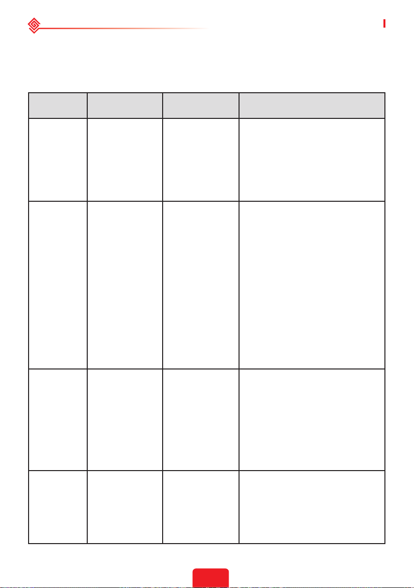
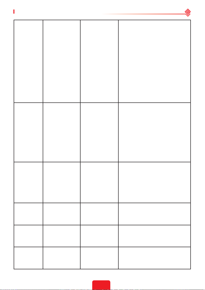
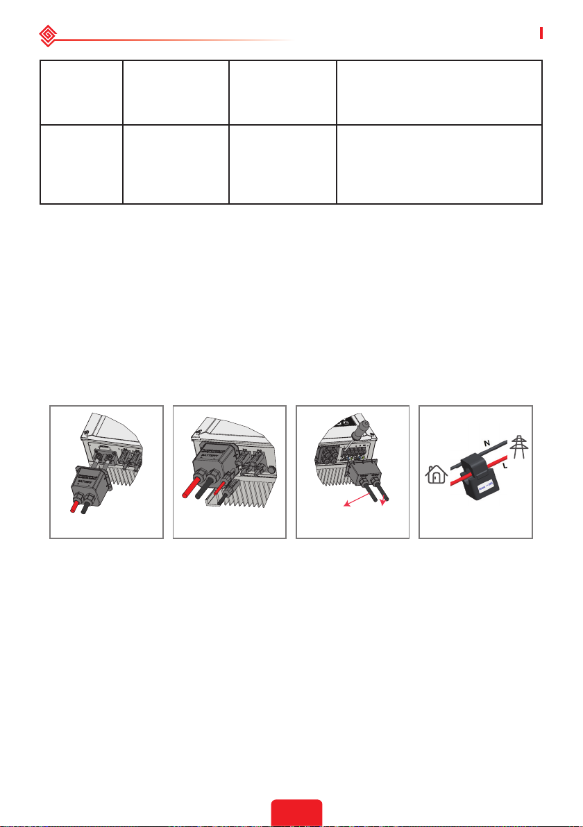
The error messages below will be displayed on PV Master App or reported by e-mail if an error
occurs.
ERROR
MESSAGE
Utility Loss Public grid power
VAC Failure Grid voltage is not
FAC Failure Grid frequency
Over
Temperature
EXPLANATION REASON SOLUTIONS
is not available
(power lost or ongrid connection
fails)
within permissible
range
is not within
permissible range
Temperature
inside of the
inverter is too
high
Inverter does
not detect the
connection of grid
Inverter detects
that AC voltage
is beyond the
normal range
required by the
safety country
Inverter detects
that the grid
frequency is
beyond the
normal range
required by the
safety country
The inverter's
working
environment
leads to a high
temperature
condition
1. Check (use multi-meter) if AC side
has voltage . Make sure grid power is
available.
2. Make sure AC cables are
connected tightly and well.
3. If all is well, please try to turn o
AC breaker and turn on again in 5
mins.
1. Make sure safety country of the
inverter is set right.
2. Check (use multi-meter) if the AC
voltage (Between L & N) is within a
normal range (also on AC breaker
side)
a. If the AC voltage is high, then
make sure the AC cable complies
with that required on user manual
and the AC cable is not too long.
b. If the voltage is low, make sure
the AC cable is connected well and
the jacket of the AC cable is not
compressed into the AC terminal.
3. Make sure the grid voltage of your
area is stable and within normal
range.
1. Make sure the safety country of
the inverter is set right.
2. If safety country is right, then
please check on the inverter display
if AC frequency (Fac) is within a
normal range.
3. If FAC failure only appears a
few times and is resolved soon, it
should be caused by occasional grid
frequency unstability.
1. Try to decrease surrounding
temperature.
2. Make sure the installation
complies with the instruction on
inverter user manual.
3. Try to close the inverter for 15
mins, then start up again.
24
Page 28
User Manual V1.1-2022-01-05 04 OTHER
Isolation
Failure
Ground Failure
Relay Check
Failure
DC Injection
High
EEPROM R/W
Failure
SPI Failure
Ground insulation
impedance of PV
string is too low
Ground leakage
current is too high
Self checking of
relay failure
/
/
Internal
communication
failure
Isolation failure
could be caused
by multiple
reasons like that
the PV panels are
not grounded
well, DC cable
is broken, PV
panels are aged
or surrounding
humidity is
comparatively
heavy, etc.
Ground failure
could be caused
by multiple
reasons like
that the neutral
cable on the
AC side is not
connected well or
the surrounding
humidity is
comparatively
heavy, etc.
Neutral & ground
cables are not
connected well on
AC side or just an
occasional failure
The inverter
detects a higher
DC component in
AC output
Caused by a
strong external
magnetic eld etc.
Caused by a
strong external
magnetic eld etc.
1. Use multi-meter to check if the
resistance between earth & inverter
frame is close to zero. If it's not,
please ensure that the connection
is well.
2. If the humidity is too high,
isolation failure may occur.
3.Check the resistance between
PV1+/PV2+/PV3+/PV4/+BAT+/PV- to
earth. If the resistance is lower than
the minimum isolation resistance
shown in the table( chapter 2.4.2 ) ,
check the system wiring connection.
4. Try to restart the inverter.Check
if the fault still occurs. If not, it
means it is caused by an occasional
situation, or contact after-sales
Check (use multi-meter) if there is
voltage (normally should be close
to 0V) between earth & inverter
frame. If there is a voltage, it means
the neutral & ground cables are not
connected well on the AC side. If it
happens only in the early morning/
dawn /rainy days with higher air
humidity and is recovered soon, it
should be normal.
Check (use multi-meter) if there is
high voltage (normally should be
lower than 10V) between N & PE
cable on the AC side. If the voltage
is higher than 10V, it means the
Neutral & ground cable are not
connected well on AC side or restart
inverter.
.Try to restart the inverter,check
if it still occurs.If not,it is just an
occasional situation.Otherwise,
contact after-sales immediately.
Try to restart the inverter,check
if it still occurs.If not,it is just an
occasional situation.Otherwise,
contact after-sales immediately.
Try to restart the inverter,check
if it still occurs.If not,it is just an
occasional situation.Otherwise,
contact after-sales immediately.
25
Page 29
04 OTHER User Manual V1.1-2022-01-05
DC Bus High BUS voltage is
over-high
/ Try to restart the inverter. Check
if the fault still occurs. If not, it
means it is caused by an occasional
situation,or contact after-sales.
Back-Up Over
Load
Back-up side is
over loaded
Total back-up load
power is higher
than the back-up
Decrease back-up loads to make sure
the total load power is lower than
back-up nominal output power.
nominal output
power
4.2 Troubleshooting
Checks Before Turning On AC Power
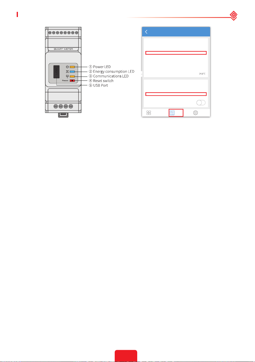
• Battery connections: Conrm that the connections between the inverter and battery: the
polarities (+/-) are not reversed. Refer to gure 4.2-1
• PV input connection: Conrm the connections between the inverter and PV panels: the
polarities (+/-) are not reversed. Refer to gure 4.2-2.
• On-grid & backup connections: Conrm that the on-grid is connected to the power grid
and that the backup is connected to the loads: the polarities (e.g. L/N are in sequence) are not
reversed. Refer to gure 4.2-3.
• Smart Meter & CT connections: Make sure that the Smart Meter and CT are connected
between the house loads and the grid, and follow the Smart Meter direction sign on the CT.
Refer to gure 4.2-4.
Grid
House
To Back-Up Load To Public Load
Loads
Figure 4.2-1 Figure 4.2-2 Figure 4.2-3 Figure 4.2-4
Checks At Startup And Turning On AC Power
Battery settings, BMS communication and safety country setting:
After connecting the Solar-Wi-Fi* (*The Wi-Fi signal is named as the last 8 characters of the
inverter's serial number.). Check the PV Master App "Param" to make sure that the battery type
is the same as was installed. Also check that the "Safety Country" setting is correct. If it is not
correct, please set is correctly in “Set”.
26
Page 30
User Manual V1.1-2022-01-05 04 OTHER
Param
Battery (Battery-Box H 11.5)
Battery Status
Battery Data
BMS Status
SOH (From BMS)
Protocol Code
Charge Current Limit (From BMS)
Discharge Current Limit (From BMS)
Waring (From BMS)
Temperature (From BMS)
Inverter
SN
Firmware Version
Safety Country
Work Status
Error
Overview Param Set
SOC: 79%, Discharge
479.9V / 0.0A / 0.08kW
Normal
100.0%
20.0A
25.0A
Normal
93648ET172W0003
02024
Brazil
Normal (Backup)
256
Note: For compatible lithium batteries, the BMS status will display "Normal" after selecting the correct
battery company.
Problems During Operation
The inverter does not start up with battery only
Solution:
Make sure that the battery voltage is greater than 48V. Otherwise, the battery cannot start the
inverter.
The inverter did not start up with PV only
Solution:
1. Make sure the PV voltage is greater than 125V.
2. Make sure that, for the connection between the inverter and PV panels, the polarities are (+/-)
not reversed.
The hybrid inverter does not discharge or output without the PV or when the PV power is
less than the load power
Solution:
1. Check whether the communications between the inverter and Smart Meter are OK.
2. Make sure the load power is greater than 150W.
a. The battery will not discharge continuously unless the load power is greater than 150W.
b. If the battery does not discharge when the Meter power is greater than 150W, please check
the Smart Meter & CT connections and directions.
3. Make sure the SOC (State of discharge) is greater than 1-DOD (Depth of discharge). Or, if
the battery is discharged to below 1-DOD, the battery will only discharge again when SOC is
charged to (20%+1-DOD/2 (if battery discharge is needed immediately, the user should restart
the battery).
4. Check on the APP whether the charge time has already been set because during the charge
time, the battery will not discharge (battery will charge in priority during times of concurrent
charge/discharge).
The battery does not charge when the PV power is greater than the load power
Solution:
1. Check if charge voltage on App(in "param")is properly set(for lead-acid battery), as battery
cannot charge if battery voltage reaches charge voltage.
2. Check the discharge time setting on App.
3. Check if battery is fully charged or not, or if battery voltage reaches "charge voltage" or not.
27
Page 31

04 OTHER User Manual V1.1-2022-01-05
High power uctuations during battery charge or discharge
Solution:
1.Check if there are uctuations in load power.
2.Check if there are uctuations in PV power.
Battery does not charge
Solution:
1. Make sure that BMS communications are OK on the PV Master App.
2. Check if the CT is connected at the right position and is connected in the right direction per
the User Manual.
3. Check if the total load power is signicantly higher than the PV power.
Questions & Answers (Q & A)
About the Wi-Fi Conguration
Q: Why can't I nd the Solar-Wi-Fi* signal on mobile devices?
A: Normally the Solar-Wi-Fi* signal can be seen immediately after inverter has powered up.
However, the Solar-Wi-Fi signal will disappear when the inverter connects to the internet. If
changes to the settings are required to connect to the router for changes. If you cannot nd the
Wi-Fi signal or connect to the router, please try to reload the Wi-Fi.
Q: Why can't I connect to the Solar-Wi-Fi* signal on my phone?
A: The Wi-Fi module can only connect to one device at a time. If the signal is already connected
to another device at the same time, you will not be able to connect to the signal.
Q: Why does the Wi-Fi module fail to connect to network after I choose the right router hotspot
and enter the right passwords?
A: It's possible that there are special characters not supported by module in the hotspot
passwords. Please modify the password to consist of only Arabic numerals or uppercase /
lowercase letters.
About Battery Operation
Q: Why does the battery not discharge when the grid is not available but it discharges normally
when the grid is available?
A: On the APP, the o-grid output and backup function should be turned on to force the battery
to discharge under o-grid mode.
Q: Why is there no output on the backup side?
A: For backup supply, "Backup Supply" on the PV Master App must be turned on. In o-grid
mode or when the grid power is disconnected, the "O-Grid Output Switch" function must be
turned on as well.
Note: When turning the "O-Grid Output Switch" on, do not restart the inverter or battery. Otherwise, the
function will be switched o automatically.
Q: Why does the battery SOC suddenly jump to 95% on the Portal?
A: This normally happens when BMS communications fail when using lithium batteries. If the
batteries enter oat charge mode, the SOC is automatically reset to 95%.
Q: The battery cannot be fully charged to 100%?
A: The battery will stop charging when the battery voltage reaches the charge voltage set in the
PV Master App.
28
Page 32

User Manual V1.1-2022-01-05 04 OTHER
Q: Why does the battery switch always trip when it starts up (lithium battery)?
A: The switch of the lithium battery trips because of following reasons:
1. BMS communication fails.
2. The battery SOC is too low and the battery trips to protect itself.
3. An electrical short-circuit has occurred on the battery connection side. Alternatively, for other
reasons, Please contact the after-sales department.
Q: Which battery should I use for the inverter?
A: For the inverter, it can connect to lithium batteries which have compatibility with inverters
with nominal voltages from 180 V to 600 V. For compatible lithium batteries, please refer to the
battery list in the PV Master App.
About PV Master Operation And Monitoring
Q: Why can't I save settings on the PV Master App?
A: This could be caused by losing the connection to Solar-Wi-Fi *.
1. Make sure you have already connected to Solar-Wi-Fi* (make sure that no other devices are
connected) or to the router (if Solar-Wi-Fi* is connected to the router). The APP homepage shows
the connections.
2. Make sure you restart the inverter 10 mins after you have changed any settings because the
inverter will save the settings every 10 mins while operating in normal mode. We recommend
that parameter settings be changed when the inverter is in wait mode.
Q: Why are the data displayed on the homepage dierent from the param page, like charge/
discharge, PV value, load value, or grid value?
A: The data refresh frequency is dierent, so there will be data discrepancies between dierent
pages on the APP as well as between these shown on the portal and APP.
Q: Some columns show NA, like battery SOH, etc. Why does that happen?
A: NA means that the App has not received data from the inverter or server because of
communication problems, such as battery communications and the communications between
inverter and the App.
About the Smart Meter And Power Limit Function
Q: How to activate the output power limit function?
A: This function can be activated by following these steps:
1. Make sure the Smart Meter connections and communications are functioning correctly.
2. Turn on the export power limit function and set the maximum output power to the grid on the
APP.
Note: Even if the output power limit is set to 0W, there might still be a deviation of a maximum
of 100 W when exporting to the grid.
Q: Why is there still power exporting to the grid after I have set the power limit to 0 W?
A: The export limit could theoretically be 0W but there will be a deviation of around 50–100 W.
Q: Can I use other meter brands to take over from the Smart Meter in the system or to change
settings in Smart Meter?
A: No, because the communication protocol is integrated into the inverter and Smart Meter,
other meter brands cannot communicate. Also, any change to the manual settings could cause a
meter communication failure.
Q: What is the maximum current allowed to pass through the CT on the Smart Meter?
29
Page 33

04 OTHER User Manual V1.1-2022-01-05
A: The maximum current for the CT is 120A.
Other Questions
Q: Is there a quick way to make the system work?
A: For the shortest resolution, please refer to "ES Quick Installation Instructions" and to the "PV
Master App Instructions".
Q: What kind of load can I use to connect to the backup side?
A: Please refer to User Manual on page 12.
Q: Will the warranty of the inverter still be valid if, for some special conditions, we cannot follow
100% of the User Manual instructions for installation or operation?
A: Normally we still provide technical support for problems caused by not following the
instructions in the User Manual. However we cannot guarantee any replacements or returns.
So, if there are any special conditions for which you cannot follow the instructions 100%, please
contact the after-sales department for suggestions.
4.3 Disclaimer
The inverters are transported, used and operated under environmental and electrical conditions.
The manufacturer has the right to not provide after-sales services or assistance under the
following conditions:
• The inverter is damaged during transfer.
• The inverter is out of the warranty year and an extended warranty is not purchased.
• The inverter is installed, retted, or operated in improper ways without authorization from the
manufacturer.
• The inverter is installed or used under improper environmental or technical conditions (as
mentioned in this User Manual) and without authorization from manufacturer.
• The installation or conguration of the inverter does not follow the requirements mentioned in
this User Manual.
• The inverter is installed or operated contrary to the requirements or warnings mentioned in
this User Manual.
• The inverter is broken or damaged by any force majeure, such as lightening, earthquake, re
hazard, storm and volcanic eruption etc.
• The inverter is disassembled, changed or updated on software or hardware without
authorization from the manufacturer.
• The Inverter is installed, used, or operated against any related provisions contained in
international or local policies or regulations.
• Any incompatible batteries, loads or other devices are connected to the system.
• Specications are subject to change without notice. Every eort has been made to make
this document complete, accurate and up-to-date. However, GoodWe may need to make
some improvements under certain circumstances without advance notice. GoodWe shall not
be responsible for any loss caused by this document including, but not limited omissions
errors,typographical errors, arithmetical errors or listing errors in this document.
If you have any questions or suggestions, please contact GoodWe after-sale.
Note: The manufacturer retains the right to explain all of the contents in this User Manual. To insure
IP66, the inverter must be sealed well; please install the inverters within one day of unpacking; otherwise,
please seal all unused terminals /holes; unused terminals/holes are not allowed to remain open; and
conrm that there is no risk of water or dust entering any terminals/holes.
30
Page 34
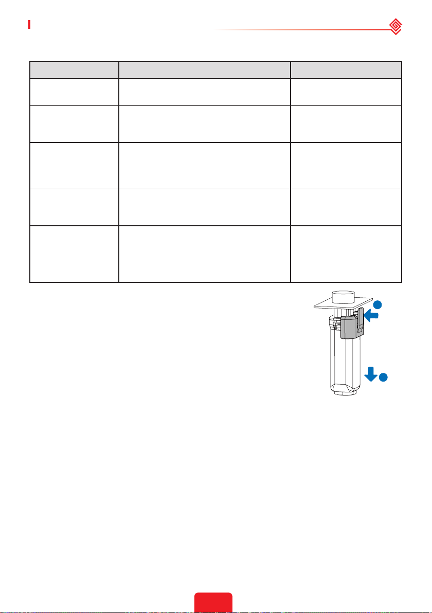
User Manual V1.1-2022-01-05 04 OTHER
Maintenance
Maintaining Item Maintaining Method Maintaining Period
System Clean
DC Switch
Electrical Connection
Sealing
THDi Test
Check the heat sink, air intake, and air
outlet for foreign matter or dust.
Turn the DC switch on and o ten
consecutive times to make sure that it is
working properly.
Check whether the cables are securely
connected. Check whether the cables are
broken, or whether there is any exposed
copper core.
Check whether all the terminals and ports
are properly sealed. Reseal the cable hole
if it is not sealed or too big.
For Australia requirements, in the THDi
test, there should add Zref between
inverter and mains.
L:0.24 Ω + j0.15 Ω; N:0.16 Ω +j0.10 Ω
L:0.15 Ω + j0.15 Ω ; N:0.1 Ω + j0.1 Ω
Once 6-12 months
Once a year
Once 6-12 months
Once a year
As needed
• WiFi module: Replace or remove the WiFi module using the WiFi
module remover, which is delivered in the package. Remove the
communication terminal next to the WiFi module rst. Place the
remover horizontally on the WiFi module, then turn the remover to
90° to fasten it and the module together. Press the remover and pull
the module to remove it as the following gure shows.
Notice: If you need to repair or replace parts, contact the after sales
service.
1
2
31
Page 35
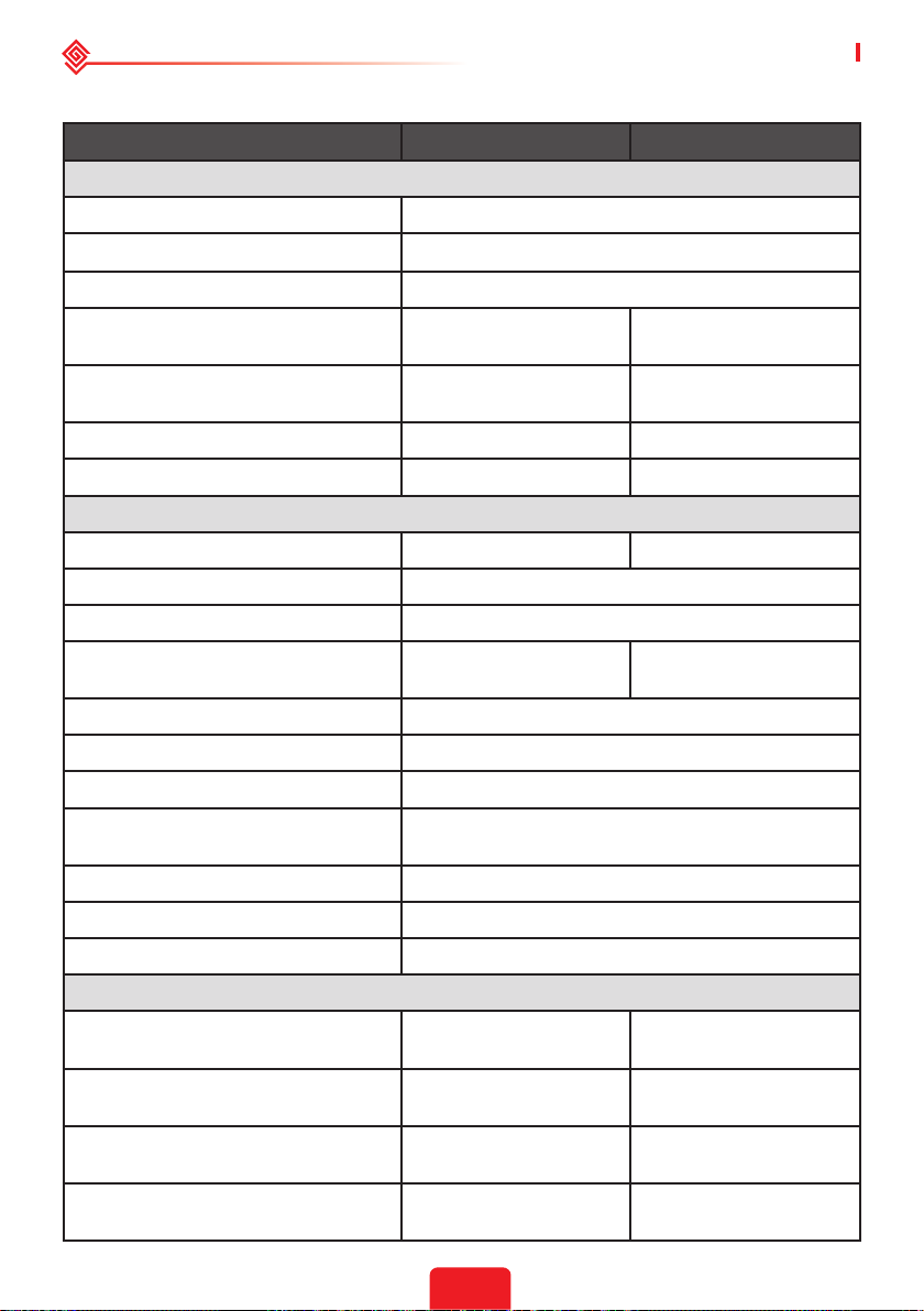
04 OTHER User Manual V1.1-2022-01-05
4.4 Technical Parameters
Technical Data GW3648D-ES
Battery Input Data
Battery Type
*1
Nominal Battery Voltage (V) 48
Battery Voltage Range (V) 40~60
Max. Continuous Charging Current
*1
(A)
Max. Continuous Discharging Current
*1
(A)
Max. Charge Power (W) 3,600 4,600
Max. Discharge Power (W) 3,600 4,600
PV String Input Data
Max. Input Power (W) 4,600 6,500
Max. Input Voltage (V) 580
MPPT Operating Voltage Range (V) 125~550
MPPT Voltage Range at Nominal
Power (V)
140~500 190~500
Start-up Voltage (V) 125
Nominal Input Voltage (V) 360
Max. Input Current per MPPT (A) 14/14 or 11/11
Max. Short Circuit Current per MPPT
(A)
Max. Backfeed Current to The Array (A) 0
Number of MPP Trackers 2
Number of Strings per MPPT 1
AC Output Data (On-grid)
Nominal Apparent Power Output to
Utility Grid (VA)
Max. Apparent Power Output to Utility
Grid (VA)
*7
*2
Nominal Apparent Power from Utility
Grid (VA)
Max. Apparent Power from Utility Grid
(VA)
3,680 5,000
3,680 5,000
7,360 9,200
7,360 9,200
*9
GW5048D-ES
Li-Ion
75 100
75 100
*11
17.5/17.5 or 13.8/13.8
*11
*10
32
Page 36
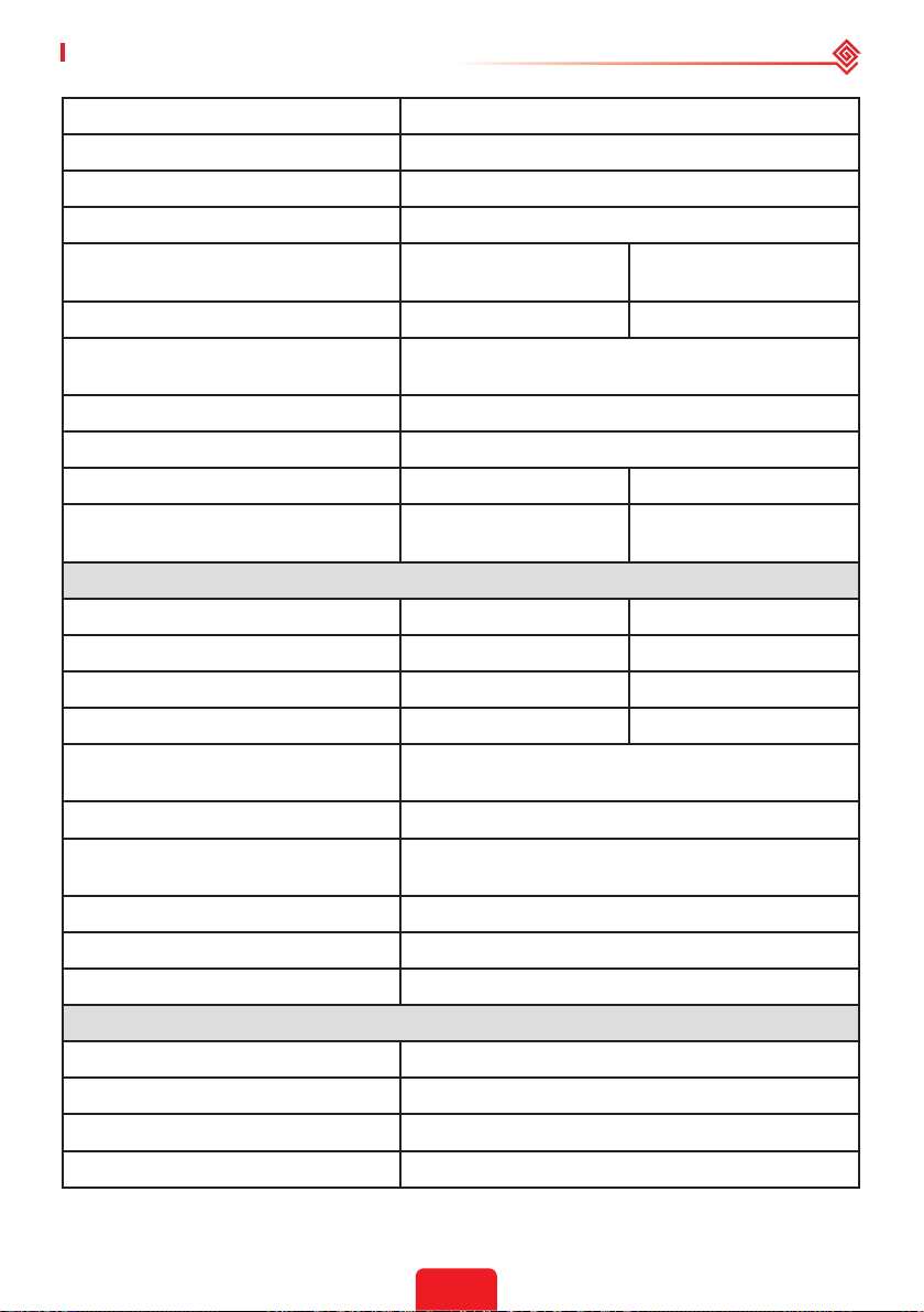
User Manual V1.1-2022-01-05 04 OTHER
Nominal Output Voltage (V) 230
Output Voltage Range (V) 0~300
Nominal AC Grid Frequency (Hz) 50/60
AC Grid Frequency Range (Hz) 45~65
Max. AC Current Output to Utility Grid
(A)
16.0
*8
24.5
Max. AC Current From Utility Grid (A) 32.0 40.0
Max. Output Fault Current (Peak and
Duration) (A)
Inrush Current (Peak and Duration) (A) 60@3μs
Power Factor ~1 (Adjustable from 0.8 leading to 0.8 lagging)
Max. Total Harmonic Distortion <3% <3%
Maximum Output Overcurrent
Protection (A)
30 30
AC Output Data (Back-up)
Back-up Nominal Apparent Power (VA) 3,680 4,600
Max. Output Apparent Power (VA)
*3
3,680 (5,520@10sec) 4,600 (6,900@10sec)
Nominal Output Current (A) 16.0 20.0
Max. Output Current (A) 16.0 20.0
Max. Output Fault Current (Peak and
Duration) (A)
Inrush Current (Peak and Duration) (A) 60@3μs
Maximum Output Overcurrent
Protection (A)
30
Nominal Output Voltage (V) 230 (±2%)
Nominal Output Frequency (Hz) 50/60 (±0.2%)
Output THDv (@Linear Load) <3%
Eciency
Max. Eciency 97.6%
European Eciency 97.0%
Max. Battery to AC Eciency 94.0%
MPPT Eciency 99.9%
33
Page 37
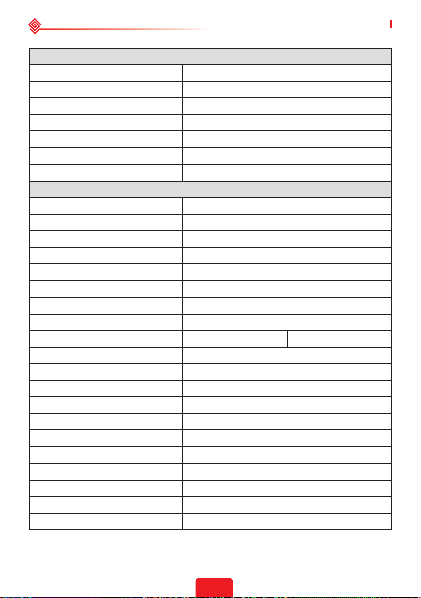
04 OTHER User Manual V1.1-2022-01-05
Protection
PV Insulation Resistance Detection Integrated
Residual Current Monitoring Integrated
PV Reverse Polarity Protection Integrated
Anti-islanding Protection Integrated
AC Overcurrent Protection Integrated
AC Short Circuit Protection Integrated
AC Overvoltage Protection Integrated
General Data
Operating Temperature Range (℃) -25~+60
Relative Humidity 0~95%
Max. Operating Altitude (m) 3000
Cooling Method Natural Convection
User Interface LED, APP
Communication with BMS
*4
RS485, CAN
Communication with Meter RS485
Communication with Portal WiFi
Weight (kg) 28.0 30.0
Dimension (W×H×D mm) 516×440×184
Noise Emission (dB) <25
Topology Non-isolated
Self-consumption at Night (W) <13
Ingress Protection Rating IP65
DC Connector MC4 (4~6 mm2)
AC Connector Feed-Through Terminal Blocks UW10
Environmental Category 4K4H
Overvoltage Category DC II / AC III
Protective Class I
Storage Temperature (℃) -40~+85
34
Page 38
User Manual V1.1-2022-01-05 04 OTHER
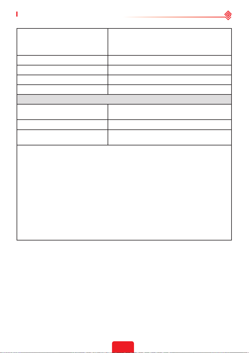
Battery: A
The Decisive Voltage Class (DVC)
PV: C
AC: C
COM: A
Mounting Method Wall Mounted
Active Anti-islanding Method AFDPF+AQDPF
*5
Type of Electrical Supply System Single Phase TN/TT System
Country of Manufacture China
Certications & Standards
Grid Regulation
*6
VDE-AR-N 4105, VDE 0126-1-1, EN 50549-1, G98,
G100, CEI 0-21, AS/NZS4777.2, NRS 097-2-1
Safety Regulation IEC62109-1&2, IEC62040-1
EMC
EN61000-6-1, EN61000-6-2, EN61000-6-3, EN61000-6-
4, EN 61000-4-16, EN 61000-4-18, EN 61000-4-29
*1: The actual charge and discharge current also depends on the battery.
*2: 4600 for VDE 0126-1-1 &VDE-AR-N4105 &NRS 097-2-1, 5100 for CEI 0-21(GW5048D-ES);
4050 for CEI 0-21(GW3648D-ES).
*3: Can be reached only if PV and battery power is enough.
*4: CAN communication is congured by default. If 485 communication is used, please replace
the corresponding communication line.
*5: AFDPF: Active Frequency Drift with Positive Feedback, AQDPF: Active Q Drift with Positive
Feedback.
*6: Not all certications & standards listed, check the ocial website for details.
*7: 4600 for VDE 0126-1-1 &VDE-AR-N4105 &NRS 097-2-1, 4600 for CEI 0-21(GW5048D-ES).
*8: 18 for CEI 0-21.
*9: FOR AUSTRALIA ONLY. Model GW3648D-ES inverters are designed without DC switch. For
inverters designed with DC switch, the model name should be GW3648C-ES.
*10: FOR AUSTRALIA ONLY. Model GW5048D-ES inverters are designed without DC switch. For
inverters designed with DC switch, the model name should be GW5048C-ES.
*11: Subject to the nameplate.
35
Page 39

04 OTHER User Manual V1.1-2022-01-05
4.5 Quick Checklist To Avoid Dangerous Conditions
1. The inverter must not be installed near ammable or explosive materials or near equipment
with strong electromagnetic elds.
2. Remember that this inverter is heavy! Please be careful when lifting from the package.
3. Make sure that the battery breaker is o and that the nominal battery voltage meets ES
specications before connecting the battery to the inverter; make sure that the inverter is
totally isolated from both PV and AC power.
4. Make sure that the inverter is totally isolated from all DC or AC power before connecting the
AC cable.
5. Make sure the AC cable is totally isolated from AC power before connecting the Smart Meter
and CT.
36
Page 40
User Manual V1.1-2022-01-05 Appendix
Appendix
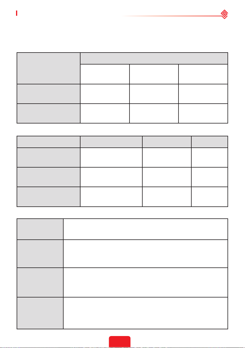
Protection category denition
Moisture location category denition
Level
Moisture Parameters
3K3 4K3 4K4H
Temperature Range 0~+40°C -33~+40°C ~20~+55°C
Moisture Parameters 5%~85% 15%~100% 4%~100%
Environment category denition
Environment Condition Ambient Temperature Relative Humidity Applied to
Outdoor -20~50°C 4%~100% PD3
Indoor Unconditioned -20~50°C 5%~95% PD3
Indoor conditioned 0~40°C 5%~85% PD2
Overvoltage category denition
Category I
Category II
Category III
Category IV
Applies to equipment connected to a circuit where measures have been
taken to reduce transient overvoltage to a low level.
Applies to equipment not permanently connected to the installation.
Examples are appliances, portables tools and other plug-connected
equipment.
Applies to a xed equipment downstream, including the main
distribution board. Examples are switchgear and other euiquipment in
an industrial installation.
Applies to equipment permanently connected at the origin of an
installation (upstream of the main distribution board). Examples are
electricity meters, primary over-current protection equipment and other
equipment connected directly to outdoor open lines.
37
Page 41
Appendix User Manual V1.1-2022-01-05
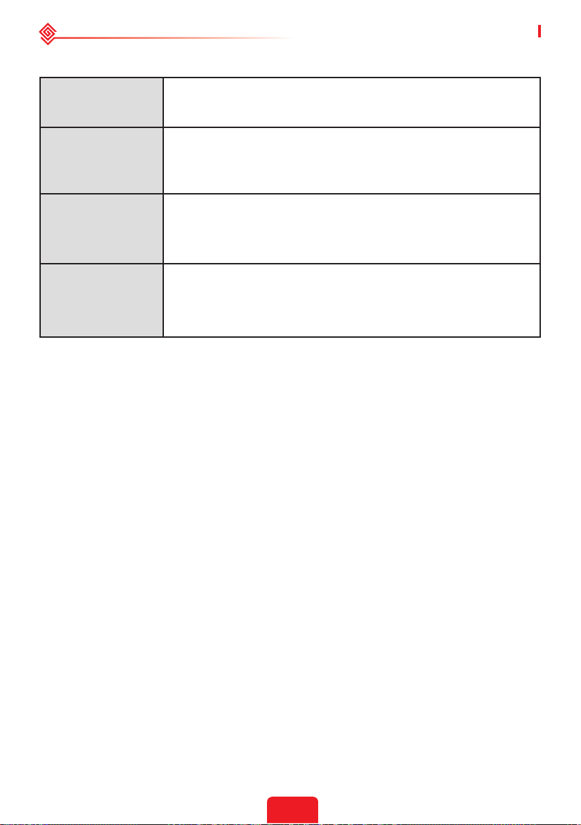
Pollution degree denition
Pollution Degree I
Pollution Degree II
Pollution Degree III
Pollution Degree IV
No pollution or only dry, non-conductive polllution occurs. The
pollution has no inuence.
Normally only non-conductive pollution occurs. Occasionally, however,
a temporary conductivity caused by condensation must be expected.
Conductive pollution occurs, or dry. non-conductive pollution occurs,
which becomes conductive due to condensation, which is expected.
Persistent conductive pollution occurs, for example, the pollution
caused by conductive dust, rain or snow.
38
Page 42

GoodWe Technologies Co., Ltd.
No. 90 Zijin Rd., New District, Suzhou, 215011, China
www.goodwe.com
Local Contacts
 Loading...