

Page 1
Installation Manual
IM 1203-1
Pathnder® Remote Evaporators
Air-Cooled Screw Compressor Chillers
Model AWS, C Vintage
170 to 550 Tons (600 to 1930 kW)
HFC-134a Refrigerant
60 Hz
Group: Chiller
Part Number: IM1203-1
Date: June 2015
Page 2
Table of ConTenTs
Introduction..............................3
Installation and Application Considerations ...4
Chilled Water Piping ......................6
Remote Evaporator Dimensions............14
Isolator Information ......................18
Lifting and Mounting Locations ............26
Physical Data ...........................53
Table of ConTenTs
Table of ConTenTs
Manufactured in an ISO 9001 & ISO 14001 certied facility
©2015 Daikin Applied. Illustrations and data cover the Daikin Applied product at the time of publication and we reserve the right to
make changes in design and construction at any time without notice.
IM 1203-1 • PATHFINDER® MODEL AWS REMOTE CHILLERS 2 www.DaikinApplied.com
Page 3
Job Name
Installation Location
Customer Order Number
Model Number(s)
G.O. Number(s)
Chilled Water
Yes
No
N/A
Initials
Piping Complete
Water strainer installed on evaporator entering chilled water piping per IM
Water System filled, flushed and vented
Pumps installed and operational (rotation checked, strainers cleaned)
Controls operational (3-way valves, face/bypass dampers, bypass valves, etc.)
Water system operated and tested; flow meets unit design requirements
Flow switch installed and wired
Vent installed on evaporator
Glycol at design %
Electrical
Yes
No
N/A
Initials
Building controls operational
Power leads have been checked for proper phasing and voltage
All interlock wiring complete and compliant with Daikin specifications
Power applied at least 24 hours before startup
Oil heaters energized at least 24 hours before startup
Chiller components (EXV Sensors Transducers) installed and wired properly.
*Wiring complies with National Electrical Code and local codes (See Notes)
Remote EXV wired with shielded cable
Miscellaneous
Yes
No
N/A
Initials
Unit control switches all off
Remote Evaporator Piping factory reviewed and approved
All refrigerant components/piping leak tested, evacuated and charged
Thermometers, wells, gauges, control, etc., installed
Minimum system load of 80% capacity available for testing/adjusting controls
Document Attached: Technical Breakdown from Selection Software
Document Attached: Final Order Acknowledgement
Document Attached: Remote evaporator piping approval
Notes: The most common problems delaying start-up and affecting unit reliability are:
3. Items on this list incorrectly acknowledged may result in delayed start and extra expenses incurred for return trips.
Contractor Representative
Daikin Applied Sales Representative
Signed:
Signed:
Name:
Name:
Company:
Company:
Date:
Date:
Phone/Email:
Phone/Email:
Pre-Start Checklist – Screw Chillers
Must be completed, signed and provided to Daikin Applied at least 2 weeks prior to requested start date.
*Power leads connected to power block or optional disconnect
1. Field installed compressor motor power supply leads too small. Questions: Contact the local Daikin sales representative*. State size, number and
type of conductors and conduits installed:
a. From Power supply to chiller
* Refer to NEC Article 430-22 (a)
Cut Here
2. Remote Evaporator piping incomplete or incorrect. Provide approved piping diagrams.
©2014 Daikin Applied Form SF01017 P/N 331977001 10OCT2014
Page 4

Page 5
InTroduCTIon
This manual contains data specic to AWS-C chiller remote evaporators. Data that is common to both packaged and remote
evaporator models can be found in the current version of the catalog and the unit installation manual available on www.
DaikinApplied.com, and includes:
• Electrical Data
• Pressure Drops
WARNING
Electric shock hazard. Improper handling of this equipment can cause personal injury or equipment damage. This equipment must
be properly grounded. Connections to and service of the MicroTech® control panel must be performed only by personnel that are
knowledgeable in the operation of the equipment being controlled.
• Performance Data (subject to adjustment factor)
• Sound Data
InTroduCTIon
HAZARD IDENTIFICATION INFORMATION
DANGER
Dangers indicate a hazardous situation, which will result in death or serious injury if not avoided.
WARNING
Warnings indicate potentially hazardous situations, which can result in property damage, severe personal injury, or death if not
avoided.
CAUTION
Cautions indicate potentially hazardous situations, which can result in personal injury or equipment damage if not avoided.
www.DaikinApplied.com 3 IM 1203-1 • PATHFINDER® MODEL AWS REMOTE CHILLERS
Page 6
InsTallaTIon and applICaTIon ConsIderaTIons
InsTallaTIon and applICaTIon ConsIderaTIons
Shipment Method
AWS chillers with remote evaporators ship in three pieces.
• Outdoor condensing unit
• Remote evaporator
• Refrigerant specialties kit with the unit has the following
components for eld installation:
— Filter-drier and cores for eld piping
— Sight glass
— Electronic expansion valve
— Solenoid valve
— Evaporator vent and drain shutoff valves - waterside
— Charging Valve (on non-economizer models)
— Suction coupling and ange to attachment evaporator
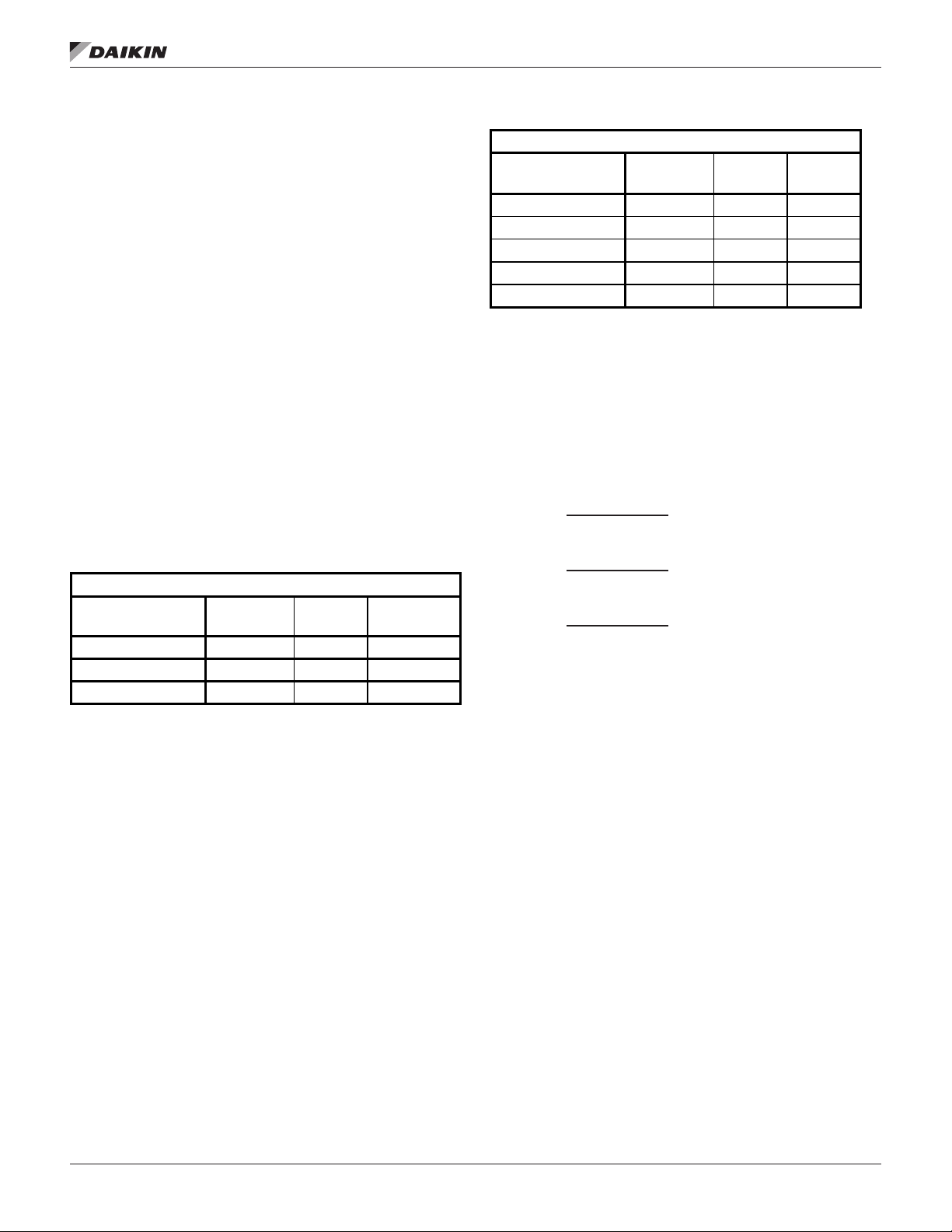
Performance Derate Data
AWS performance data can be found in the current version of
the catalog, available on www.DaikinApplied.com or the local
sales ofce. There is a derate to the performance of an AWS
with remote evaporator due to eld installed refrigerant line
losses exceeding those found on the packaged arrangement.
For preliminary purposes, use the following as an estimate:
Table 1: Approximate Initial Derate Factors
AWS - C
Actual Line Length
Up To:
75’ 0.96 0.98 0.97
50’ 0.97 0.99 0.98
25’ 0.98 0.99 0.99
Once the pipe design is nalized, the actual adjustment is
determined using the following procedure.
Derate Procedure
1. Sketch the liquid and suction piping, including the actual
pipe lengths and all ttings.
2. Using the recommended pipe sizes from Table 5 and
Table 6, add up the equivalent pressure drop for the
ttings in the suction line. Add this value to the actual
linear feet of tubing to determine the total equivalent
length (TEL) for the piping run.
3. Using Table 5 and Table 6, determine the pressure
drop (in degrees F) based on the TEL. Interpolation
is permitted, extrapolation is not. Consult the Daikin
Technical Response Center for piping installations
outside the published recommendations.
4. Determine the derate factors from Table 2 based on the
suction line pressure drop.
Capacity
Derate
Power
Derate
EER Derate
Table 2: Performance Derate Factors
AWS - C
Suction Line
Pressure Drop (
0.0 1.00 1.00 1.00
1.0 0.98 0.99 0.99
2.0 0.96 0.98 0.97
3.0 0.94 0.98 0.96
4.0 0.92 0.97 0.94
o
F)
Capacity
Derate
Power
Derate
EER
Derate
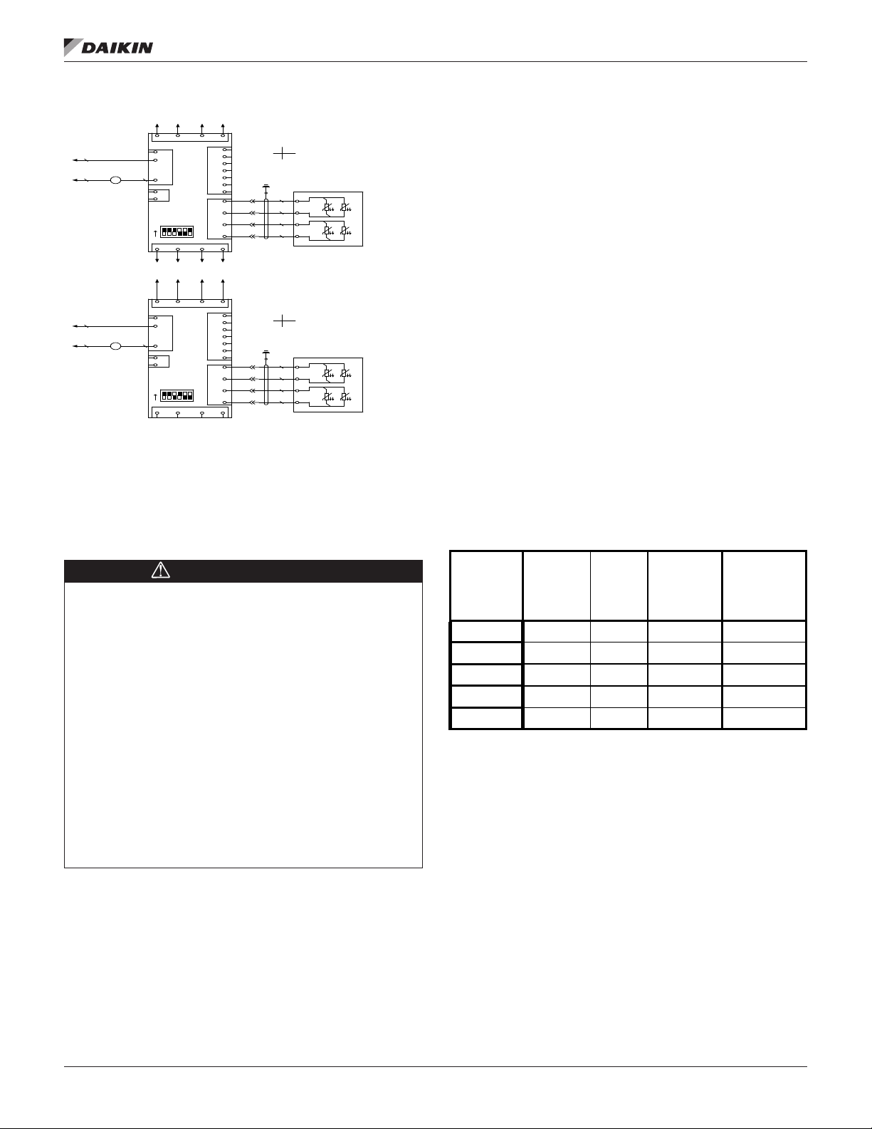
Remote Evaporator Field Wiring Notes:
1. The 110V liquid line solenoid valves (LSV) have to
be wired back to the outdoor unit. All the conduit and
wiring is to be eld supplied (14 gauge, red and white
wires, 3/8” conduit with straight and 90 degree ttings).
If additional length is required, use 14 gauge wire up
to a maximum of 100 feet. A din connector is supplied
with refrigerant specialties kits. Field to wire directly into
compressor terminal box terminal block per below:
• Compressor #1: (LSV-1) wire 740-1A (red) wires
into compressor #1 terminal box terminal block at
TB1-2-9. Wire 740-1B (white) wires to TB1-2-10.
• Compressor #2: (LSV-2) wire 740-2A (red) wires
into compressor #2 terminal box terminal block at
TB2-2-9. Wire 740-2B (white) wires to TB2-2-10.
• Compressor #3: (LSV-3) wire 740-3A (red) wires
into compressor #3 terminal box terminal block at
TB3-2-9. Wire 740-3B (white) wires to TB3-2-10.
2. Two evaporator water temperature sensors with 100
feet of cable coiled up and attached to the unit base
for extension to the evaporator and insertion in ttings
located on the side of the inlet and outlet nozzles.
3. One suction line refrigerant temperature sensor per
circuit with 100 feet of cable coiled up and attached to
the unit base for extension to the evaporator.
4. One suction line pressure transducer per circuit with 100
feet of cable coiled up and attached to the unit base for
extension to the evaporator.
5. The electronic expansion valve has a 40-foot long cable
attached and can be used, when the outdoor unit is less
than 40 feet away. Beyond that, a junction box must be
located within 40-feet of the evaporator, and up to 60
additional feet of 14GA wire connected from the cable
to the unit, allowing up to a total distance of 100 feet.
When splicing is required the connections must be
soldered together and individually shrink wrapped to be
made water resistant. The expansion valve wiring cannot
run in conduit with other wiring that is over 24 Volts AC
Shielding must cover the wiring from the unit to the EXV,
including the splice connection.
NOTE: 14 AWG Wire Gauge sizes will use Beldon part
number 83754.
IM 1203-1 • PATHFINDER® MODEL AWS REMOTE CHILLERS 4 www.DaikinApplied.com
Page 7
InsTallaTIon and applICaTIon ConsIderaTIons
ADDRESS=3
T1 T3
T2
T4
E.E.X.V.1
1 2 3 4 5 6
ON
ADDRESS=5
T1 T3
T2
T4
E.E.X.V.2
1 2 3 4 5 6
ON
BRN
WHT
BLU
BLK
RED
GRN
WHT
BLK
RED
GRN
WHT
BLK
BLU
BLK
WHT
BRN
M16
902
900
M26
906
901
POL94E.00/MCQ
D01A
C1
D01B
DI1
R1
T3-M
X3
+5V
X1
T3-M
X2
M1-
M2+
M2-
M1+
+24V
24VGNDB-A+
A+ B-
GND
24V
POL94E.00/MCQ
D01A
C1
D01B
DI1
R1
T3-M
X3
+5V
X1
T3-M
X2
M1-
M2+
M2-
M1+
+24V
24VGNDB-A+
A+ B-
GND
24V
W1
ΘW1Θ
W2
ΘW2Θ
EXV-1
1
2
3
4
GTB5
W1
ΘW1Θ
W2
ΘW2Θ
EXV-2
1
2
3
4
GTB5
A2 A1
M16
(438)
(439)
(440)
NC
NO
903
A2 A1
M26
(538)
(539)
(540)
NC
NO
907
(847) (847) (847) (847)
(848) (848) (848) (848)
(863) (863) (863) (863)
/(756)
/(659)
/(756)
/(659)
Figure 1: Remote EXV Field Wiring
6. A ow switch must be installed in the leaving chilled
water line per manufacturer’s instructions and wired
to terminals 8 and 23 on terminal block M5 in the
chiller control panel. See Unit Field Wiring Diagram in
current version of installation manual available on www.
DaikinApplied.com.
7. Do not reduce the wire lengths of factory wiring.
Remote Evaporator Refrigerant Piping
correct pipe sizing.
5. Keep the refrigerant suction line pressure drop to a
maximum of 2 F. in saturated temperature equivalent.
6. Each suction line’s velocity must be sufcient to carry oil
considering a 25% capacity reduction in each circuit.
7. When facing the unit control box, the left-hand
compressor is circuit # 1, and the right-hand is circuit # 2.
If present, the compressor behind #2, on the right-hand
side, is circuit #3.
8. Liquid lines may be insulated to prevent collection of
condensation, if needed.
The following applies to all size units:
• Maximum linear line length cannot exceed 75 feet
• Maximum total equivalent length (TEL) cannot exceed
180 feet (75 feet for vertical suction lines)
• The evaporator cannot be located more than 20 feet
above or 30 feet below the outdoor unit.
• Suction line connection at unit = 4 1/8-inch OD each
• Underground refrigerant piping is not permitted
• Field piping must include adequate service taps for
checking lter-drier, subcooling, and superheat.
• Insulate complete suction lines. Liquid lines may be
insulated to prevent collection of condensation if required.
• Ensure the braze rod used is appropriate for the
materials being joined
Table 3: Fitting Equivalent Feet of Pipe
IMPORTANT NOTE
Service Form SF99006 (available from the local sales
Line Size
In. OD
Angle
Valve
Globe
Valve
ofce) and an isometric sketch of the Remote Piping Layout
showing pipe size, location of ttings, measured lengths,
and elevations MUST BE SUBMITTED to Daikin Technical
Response Center and reviewed at least two weeks prior
to beginning piping installation. The information can be
forwarded to Daikin Applied by the local sales ofce or sent
directly to E-mail: techresponse@daikinapplied.com
Daikin Applied service will not perform startup without
reviewed Service Form SF99006 and drawing. Installation
must match reviewed drawing.
All eld piping, wiring and procedures must comply with
design guidelines set forth in this manual and be performed
in accordance with ASHRAE, EPA, local codes and industry
standards. Any product failure caused or contributed to
by failure to comply with appropriate design guidelines
will not be covered by manufacturer’s warranty. Daikin
Technical Response Center - Phone : 540-248-9239; E-mail:
techresponse@daikinapplied.com
Careful design of refrigerant piping is necessary for proper
system operation. Design the refrigerant piping to accomplish
the following:
www.DaikinApplied.com 5 IM 1203-1 • PATHFINDER® MODEL AWS REMOTE CHILLERS
1. Assure proper refrigerant feed to the evaporator.
2. Provide practical and economical refrigerant line sizes
without excess pressure drop.
3. Maintain uniform oil return to the compressor under all
load conditions.
4. Refer to the latest version of the ASHRAE Handbook for
recommended piping practice; use included tables for
2 5/8
3 1/8
3 5/8
4 1/8
5 1/8
NOTE: TEL values for the lter-drier and solenoid valve are
already included and should not be added to the
liquid line drop.
Piping Layout
Figure 4 shows the piping layout for one of the two or three
refrigerant circuits for AWS units with a remote evaporator
without the economizer circuit. The outdoor unit, the
evaporator, and a kit of refrigerant components are shipped
as separate pieces for eld mounting, wiring, and piping. The
suction shutoff valve is standard on remote evaporator units.
Note: Field insulation of the suction lines and the liquid line on
circuits with economizers is required. The outdoor unit will have
a refrigerant charge equal to that of a packaged unit pumped
down into the condenser. The additional charge of refrigerant
and oil required by the eld piping is supplied and installed
by the customer. The location and size of the refrigerant
connections are shown on dimensional drawings available from
a Daikin Applied sales representative.
1.00 1.00 1.00 1.00
0.98 0.99 0.99 0.99
0.96 0.98 0.97 0.97
0.94 0.98 0.96 0.96
0.92 0.97 0.94 0.94
90-Degree
Std. Radius
Elbow
90-Degree
Long Radius
Elbow
Page 8
Chilled Water Piping
Figure 2: Typical Piping, Shell and Tube Evaporator
InsTallaTIon and applICaTIon ConsIderaTIons
VENT
3/8” PIPE PLUG
OUTLET
INLET
VIBRATION
ELIMINATOR
DRAIN
PROTECT ALL FIELD PIPING
AGAINST FREEZING
WATER
STRAINER
CAUTION
To prevent damage to the evaporator and potential chiller
failure, a supply strainer is required in the inlet water piping
which connects to this evaporator. This strainer must be
installed prior to operation of the chilled liquid pumps.
Field installed water piping to the chiller must include:
• A cleanable strainer installed at the water inlet to the
evaporator to remove debris and impurities before they
reach the evaporator. Install cleanable strainer within
5 feet (1500 mm) of pipe length from the evaporator
inlet connection and downstream of any welded
connections (no welded connections between strainer
and evaporator).
• AWS-C models require a strainer with perforations no
larger than 0.125” (3.2 mm) diameter. See the Inlet
Strainer Guidelines on page 7 for more information.
• A water ow switch must be installed in the horizontal
piping of the supply (evaporator outlet) water line to avoid
evaporator freeze-up under low or no ow conditions. The
ow switch may be ordered as a factory-installed option,
a eld-installed kit, or may be supplied and installed in the
eld. See IOM for more information.
• Purge air from the water system before unit start-up to
provide adequate ow through the evaporator.
• Adequate piping support, independent from the unit,
to eliminate weight and strain on the ttings and
connections.
It is recommended that the eld installed water piping to the
chiller include:
• Thermometers at the inlet and outlet connections of the
evaporator.
• Water pressure gauge connection taps and gauges at
LEAVING FLUID
TEMP. SENSOR
VIBRATION
ELIMINATOR
FLOW
SWITCH
VALVED
PRESSURE
GAUGE
GATE
VALV E
BALANCING
VALV E
FLOW
GATE
VALV E
FLOW
the inlet and outlet connections of the evaporator for
measuring water pressure drop.
• Shutoff valves are necessary to isolate the unit from the
piping during unit servicing.
• Minimum bends and changes in elevation to minimize
pressure drop.
• An expansion tank or regulating valve to maintain
adequate water pressure
• Vibration eliminators in both the supply and return water
lines to reduce transmissions to the building.
• Flush the system water piping thoroughly before making
connections to the unit evaporator.
• Piping insulation, including a vapor barrier, helps prevent
condensation and reduces heat loss.
• Regular water analysis and chemical water treatment
for the evaporator loop is recommended immediately at
equipment start-up.
Chilled Water Pump
The chilled water pumps must be wired to, and controlled by,
the chiller controller. The chiller controller has the capability
to selectively start pump A or B or automatically alternate
pump selection and also has standby operation capability.
The controller will energize the pump whenever at least one
circuit on the chiller is enabled to run, whether there is a call for
cooling or not. This helps ensure proper unit startup sequence.
The pump will also be turned on when the water temperature
goes below the Freeze Setpoint for longer than a specied time
to help prevent evaporator freeze-up.
IM 1203-1 • PATHFINDER® MODEL AWS REMOTE CHILLERS 6 www.DaikinApplied.com
Page 9
InsTallaTIon and applICaTIon ConsIderaTIons
CAUTION
Adding glycol or draining the system is the recommended
method of freeze protection. If the chiller does not have the
ability to control the pumps and the water system is not drained
in temperatures below freezing, catastrophic evaporator
failure may occur.
Failure to allow pump control by the chiller controller may
cause the following problems:
1. If any device other than the chiller attempts to start the
chiller without rst starting the pump, the chiller will lock
out on the No Flow alarm and require manual reset.
2. If the chiller evaporator water temperature drops below
the “Freeze setpoint” the chiller will attempt to start the
water pumps to avoid evaporator freeze. If the chiller
does not have the ability to start the pumps, the chiller
will alarm due to lack of water ow.
3. If the chiller does not have the ability to control the
pumps and the water system is not to be drained in
temperatures below freezing, the chiller may be subject
to catastrophic evaporator failure due to freezing.
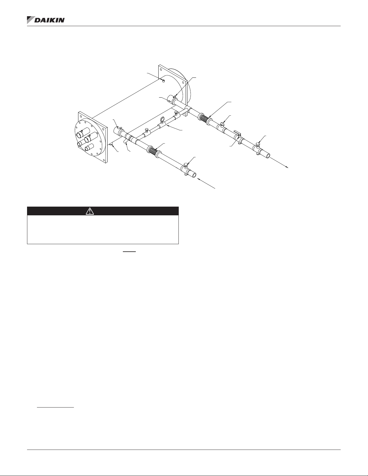
Inlet Strainer Guidelines
An inlet water strainer kit must be installed in the chilled water
piping before the evaporator inlet. Two paths are available to
meet this requirement:
1. A eld-installed kit shipped-loose with the unit is available
for all unit sizes and consists of:
• Y-type area strainer with 304 stainless steel perforated
basket, Victaulic pipe connections and strainer cap [a
strainer with perforations no larger than 0.125” (3.2
mm) diameter for AWS-C models].
• Extension pipe with two Schrader ttings that can be
used for a pressure gauge and thermal dispersion ow
switch. The pipe provides sufcient clearance from the
evaporator for strainer basket removal.
• ½-inch blowdown valve
• Two grooved clamps
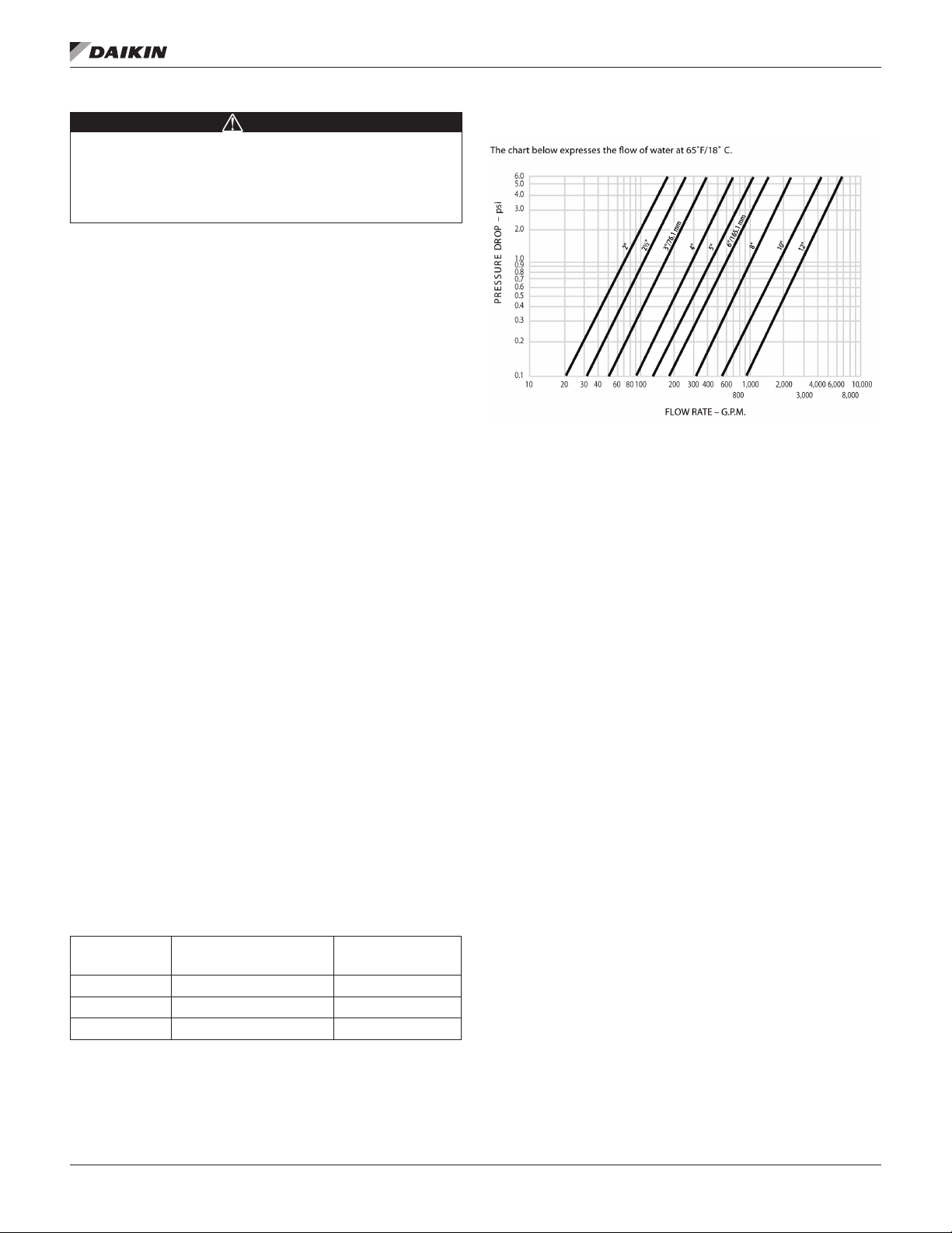
The strainer is sized per Table 4 and the pressure drop is
shown in the Strainer Pressure Drop graph.
2. A eld-supplied strainer that meets specication and
installation requirements of this manual.
Table 4: Strainer Sizing Data
Strainer Size
(in.)
6 30.5 72
8 36.0 125
10 43.0 205
Strainer Plus Pipe
Length (in.)
Strainer Weight
(lbs)
Figure 3: Strainer Pressure Drop
Evaporator Freeze Protection
Pathnder® chillers are equipped with thermostatically
controlled evaporator heaters that help protect against
freezeup down to -20°F (-28°C). The immersion heater itself
may not be able to properly protect the evaporator from
freezing without circulation of water, and it is important that
the chilled water pumps are wired to, and controlled by,
the chiller’s controller. Additionally, use at least one of the
following procedures IF the mechanical room where the remote
evaporator is installed is subject to ambient temperatures
below 32F:
1. Add a concentration of a glycol anti-freeze with a freeze
point 10°F below the lowest expected temperature. This
will result in decreased capacity and increased pressure
drop. Do not use automotive grade antifreezes as they
contain inhibitors harmful to chilled water systems. Use
only glycols specically designated for use in building
cooling systems.
2. Drain the water from outdoor equipment and piping
and blow the chiller tubes dry from the chiller. Do not
energize the chiller heater when water is drained from
the vessel.
NOTE: The heaters come from the factory connected to
the control power circuit. The control power can be
rewired in the eld to a separate 115V supply (do
not wire directly to the heater). See the eld wiring
diagram on page 60. If this is done, it should power
the entire control circuit. Mark the disconnect switch
clearly to avoid accidental deactivation of the heater
during freezing temperatures. Exposed chilled water
piping also requires protection. If the evaporator is
drained for winter freeze protection, the heaters must
be de-energized to prevent heater burnout.
www.DaikinApplied.com 7 IM 1203-1 • PATHFINDER® MODEL AWS REMOTE CHILLERS
Page 10
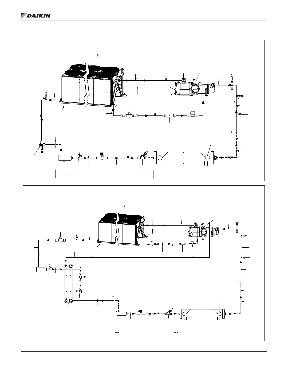
Figure 4: Piping Schematic, Remote Evaporator (One of Two Circuits)
*R3319947010E3*
AWS Remote Evaporator Models (No Economizer)
AWS Remote Evaporator Models ( With Economizer)
*R3319947010E4*
CHAR GING
VALVE
LIQUID
TUBIN G
FILTER
DRYE R
SOLENOID
VALVE
SIGHT
GLASS
EXPAN SION
VALVE
WATER IN
WATER OUT
DX EV APORATOR
SUCTI ON
TUBIN G
(STUB TUBE)
OIL PRES S.
TRANS DUCER
WITH SCHRAD ER
VALVE
DISC HARGE
TUBIN G
AIR
FLOW
AIR
FLOW
CONDE NSER
ASSEMB LY
F3/F4
COMPRE SSOR
RELIEF
VALVE
SUCTI ON
TEMP. SENS OR
SUCTI ON
TRANS DUCER
DISC HARGE
TEMP. SE NSOR
(WOE)
TEMP. SENS OR
(WIE)
TEMP. SE NSOR
OUTSID E AIR
TEMPER ATURE
(WAA)
SCHR ADER
VALVE
SCHR ADER
VALVE
SHUT-OFF
VALVE
BUTTER FLY
VALVE
RELIEF
VALVE
DISC HARGE
TRANS DUCER
SCHR ADER
VALVE
STRAIN ER
BALL
VALVE
SOLENOID
VALVE
LIQUID
INJECTI ON
TUBIN G
SUCTI ON
TRANS DUCER
SCHR ADER
VALVE
CHAR GING
VALVE
FIELD
CONNE CTION
POINT
SCHR ADER
VALVE
FIELD
CONNE CTION
POINT
FIELD PIPING
SHOWN DASHED
LIQUID
SHUTOFF
VALVE
SCHR ADER
VALVE
FIELD INSTALLED LIQUID LINE COMPONENTS
SCHR ADER
VALVE
(HEADER)
CHAR GING
VALVE
NOTE
:
PIPING SHOWN FOR ONE SYSTEM OF UNIT
.
UNIT HAS TWO INDEPENDENT SYSTEMS
.
CHAR GING
VALVE
LIQUID
TUBIN G
FILTER
DRYE R
SOLENOID
VALVE
EXPAN SION
VALVE
WATER IN
WATER OUT
DX EV APORATOR
SUCTI ON
TUBIN G
(STUB TUBE)
OIL PRES S
.
TRANS DUCER
WITH SCHRAD ER
VALVE
DISC HARGE
TUBIN G
AIR
FLOW
AIR
FLOW
COND ENSER
ASSEM BLY
F3/F4
COMPRE SSOR
RELIEF
VALVE
SUCTI ON
TEMP.
SENSOR
SUCTI ON
TRANS DUCER
DISC HARGE
TEMP. SENSOR
(WOE)
TEMP. SENSOR
(WIE)
TEMP
.
SENSOR
OUTSID E AIR
TEMPER ATURE
(WAA)
SCHR ADER
VALVE
SCHR ADER
VALVE
SCHR ADER
VALVE
SHUT-OFF
BALL VALVE
SOLENOID
VALVE
TGE
EXPAN SION
VALVE
ECONOMI ZER
SHUT-OFF
VALVE
ECONOMI ZER FLASH GA S TO COMPRES SOR INTERS TAGE
BUTTER FLY
VALVE
RELIEF
VALVE
DISC HARGE
TRANS DUCER
BALL
VALVE
SCHR ADER
VALVE
LIQUID
INJECT ION
TUBIN G
SOLENOID
VALVE
SCHR ADER
VALVE
SCHR ADER
VALVE
(HEADER)
SCHR ADER
VALVE
CHAR GING
VALVE
FIELD
CONN ECTION
POINT
SCHR ADER
VALVE
SIGHT
GLASS
SCHR ADER
VALVE
FILTER
DRYE R
FIELD
CONN ECTION
POINT
STUB
TUBE
SCHR ADER
VALVE
FIELD INSTALLED LIQUID LINE COMPONENT S
FIELD PIPING
SHOWN DASHED
STRAIN ER
CHAR GING
VALVE
SIGHT
GLASS
SUCTI ON
PRESS
.
TRANS DUCER
NOTE:
PIPING SHOWN FOR ONE SYSTEM OF UNIT.
UNIT HAS TWO INDEPENDENT SYSTEMS
.
InsTallaTIon and applICaTIon ConsIderaTIons
IM 1203-1 • PATHFINDER® MODEL AWS REMOTE CHILLERS 8 www.DaikinApplied.com
Page 11
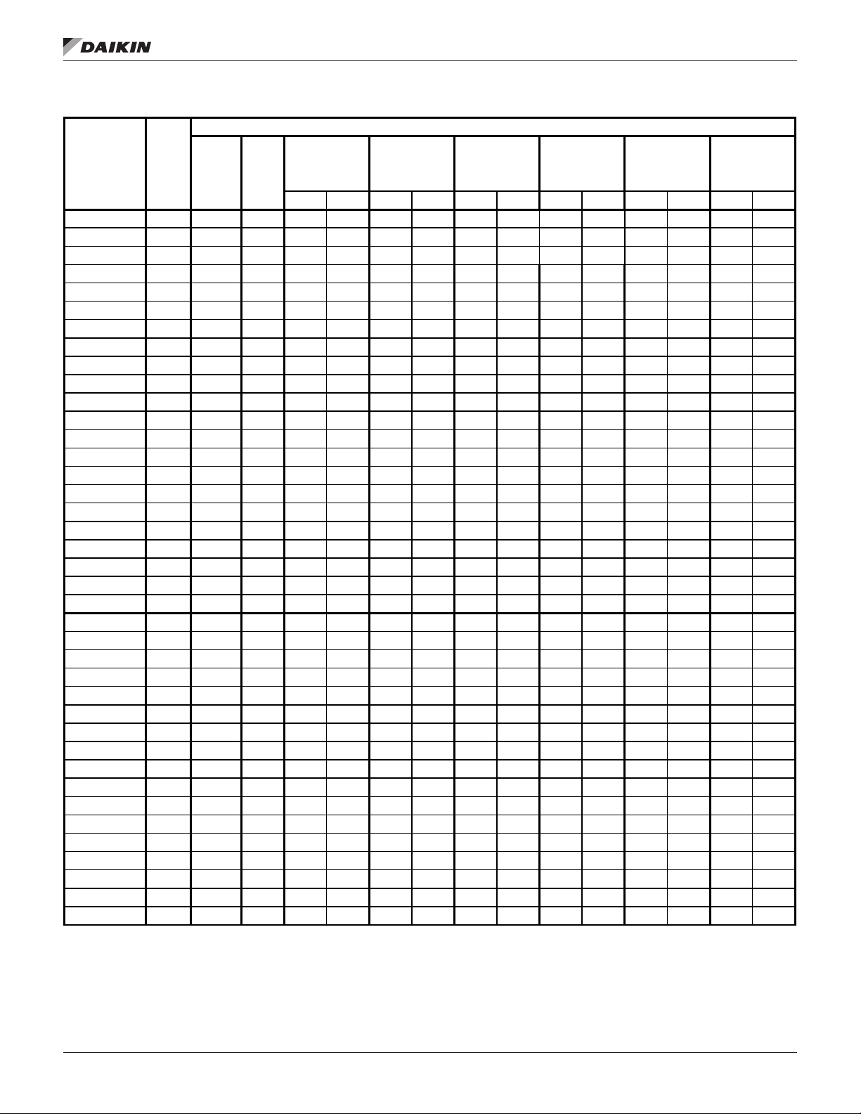
Table 5: Recommended Horizontal or Downow Suction Line Size
Recommended Horizontal or Downow Suction Line Size
InsTallaTIon and applICaTIon ConsIderaTIons
Model Circuit
AWS170CDS 1
AWS170CDS 2
AWS190CDS 1 95 4 1/8 3 5/8 1.23 3 5/8 1.84 4 1/8 1.32 4 1/8 1.66 4 1/8 1.99 4 1/8 2.38
AWS190CDS 2 95 4 1/8 3 5/8 1.23 3 5/8 1.84 4 1/8 1.32 4 1/8 1.66 4 1/8 1.99 4 1/8 2.38
AWS200CDS 1 11 5 4 1/8 3 5/8 1.73 4 1/8 1.40 4 1/8 1.87 4 1/8 2.34 4 1/8 2.80 4 1/8 3.36
AWS200CDS 2 11 5 4 1/8 3 5/8 1.73 4 1/8 1.40 4 1/8 1.87 4 1/8 2.34 4 1/8 2.80 4 1/8 3.36
AWS210CDS 1 95 4 1/8 3 5/8 1.23 3 5/8 1.84 4 1/8 1.32 4 1/8 1.66 4 1/8 1.99 4 1/8 2.38
AWS210CDS 2 11 5 4 1/8 3 5/8 1.73 4 1/8 1.40 4 1/8 1.87 4 1/8 2.34 4 1/8 2.80 4 1/8 3.36
AWS225CDS 1 11 5 4 1/8 3 5/8 1.73 4 1/8 1.40 4 1/8 1.87 4 1/8 2.34 4 1/8 2.80 4 1/8 3.36
AWS225CDS 2 11 5 4 1/8 3 5/8 1.73 4 1/8 1.40 4 1/8 1.87 4 1/8 2.34 4 1/8 2.80 4 1/8 3.36
AWS250CDS 1 11 5 4 1/8 3 5/8 1.73 4 1/8 1.40 4 1/8 1.87 4 1/8 2.34 4 1/8 2.80 4 1/8 3.36
AWS250CDS 2 135 4 1/8 4 1/8 1.25 4 1/8 1.87 4 1/8 2.49 5 1/8 1.10 5 1/8 1.32 5 1/8 1.58
AWS260CDS 1 135 4 1/8 4 1/8 1.25 4 1/8 1.87 4 1/8 2.49 5 1/8 1.10 5 1/8 1.32 5 1/8 1.58
AWS260CDS 2 135 4 1/8 4 1/8 1.25 4 1/8 1.87 4 1/8 2.49 5 1/8 1.10 5 1/8 1.32 5 1/8 1.58
AWS290CDS 1 135 4 1/8 4 1/8 1.25 4 1/8 1.87 4 1/8 2.49 5 1/8 1.10 5 1/8 1.32 5 1/8 1.58
AWS290CDS 2 155 4 1/8 4 1/8 1.60 4 1/8 2.40 5 1/8 1.13 5 1/8 1.41 5 1/8 1.69 5 1/8 2.03
AWS310CDS 1 155 4 1/8 4 1/8 1.60 4 1/8 2.40 5 1/8 1.13 5 1/8 1.41 5 1/8 1.69 5 1/8 2.03
AWS310CDS 2 155 4 1/8 4 1/8 1.60 4 1/8 2.40 5 1/8 1.13 5 1/8 1.41 5 1/8 1.69 5 1/8 2.03
AWS350CDS 1 155 4 1/8 4 1/8 1.60 4 1/8 2.40 5 1/8 1.13 5 1/8 1.41 5 1/8 1.69 5 1/8 2.03
AWS350CDS 2 185 4 1/8 4 1/8 2.20 5 1/8 1.16 5 1/8 1.55 5 1/8 1.94 5 1/8 2.33 5 1/8 2.79
AWS375CDS 1 185 4 1/8 4 1/8 2.20 5 1/8 1.16 5 1/8 1.55 5 1/8 1.94 5 1/8 2.33 5 1/8 2.79
AWS375CDS 2 185 4 1/8 4 1/8 2.20 5 1/8 1.16 5 1/8 1.55 5 1/8 1.94 5 1/8 2.33 5 1/8 2.79
AWS400CTS 1 135 4 1/8 4 1/8 1.25 4 1/8 1.87
AWS400CTS 2 135 4 1/8 4 1/8 1.25 4 1/8 1.87 4 1/8 2.49 5 1/8 1.10 5 1/8 1.32 5 1/8 1.58
AWS400CTS 3 135 4 1/8 4 1/8 1.25 4 1/8 1.87 4 1/8 2.49 5 1/8 1.10 5 1/8 1.32 5 1/8 1.58
AWS425CTS 1 135 4 1/8 4 1/8 1.25 4 1/8 1.87 4 1/8 2.49 5 1/8 1.10 5 1/8 1.32 5 1/8 1.58
AWS425CTS 2 135 4 1/8 4 1/8 1.25 4 1/8 1.87 4 1/8 2.49 5 1/8 1.10 5 1/8 1.32 5 1/8 1.58
AWS425CTS 3 155 4 1/8 4 1/8 1.60 4 1/8 2.40 5 1/8 1.13 5 1/8 1.41 5 1/8 1.69 5 1/8 2.03
AWS450CTS 1 155 4 1/8 4 1/8 1.60 4 1/8 2.40 5 1/8 1.13 5 1/8 1.41 5 1/8 1.69 5 1/8 2.03
AWS450CTS 2 155 4 1/8 4 1/8 1.60 4 1/8 2.40 5 1/8 1.13 5 1/8 1.41 5 1/8 1.69 5 1/8 2.03
AWS450CTS 3 135 4 1/8 4 1/8 1.25 4 1/8 1.87 4 1/8 2.49 5 1/8 1.10 5 1/8 1.32 5 1/8 1.58
AWS470CTS 1 155 4 1/8 4 1/8 1.60 4 1/8 2.40 5 1/8 1.13 5 1/8 1.41 5 1/8 1.69 5 1/8 2.03
AWS470CTS 2 155 4 1/8 4 1/8 1.60 4 1/8 2.40 5 1/8 1.13 5 1/8 1.41 5 1/8 1.69 5 1/8 2.03
AWS470CTS 3 155 4 1/8 4 1/8 1.60 4 1/8 2.40 5 1/8 1.13 5 1/8 1.41 5 1/8 1.69 5 1/8 2.03
AWS500CTS 1 155 4 1/8 4 1/8 1.60 4 1/8 2.40 5 1/8 1.13 5 1/8 1.41 5 1/8 1.69 5 1/8 2.03
AWS500CTS 2 155 4 1/8 4 1/8 1.60 4 1/8 2.40 5 1/8 1.13 5 1/8 1.41 5 1/8 1.69 5 1/8 2.03
AWS500CTS 3 185 4 1/8 4 1/8 2.20 5 1/8 1.16 5 1/8 1.55 5 1/8 1.94 5 1/8 2.33 5 1/8 2.79
AWS525CTS 1 185 4 1/8 4 1/8 2.20 5 1/8 1.16 5 1/8 1.55 5 1/8 1.94 5 1/8 2.33 5 1/8 2.79
AWS525CTS 2 185 4 1/8 4 1/8 2.20 5 1/8 1.16 5 1/8 1.55 5 1/8 1.94 5 1/8 2.33 5 1/8 2.79
Nominal
Tons Per
Circuit
Tubing
Conn.
Size At
Unit
95 4 1/8 3 5/8 1.23 3 5/8 1.84 4 1/8 1.32 4 1/8 1.66 4 1/8 1.99 4 1/8 2.38
95 4 1/8 3 5/8 1.23 3 5/8 1.84 4 1/8 1.32 4 1/8 1.66 4 1/8 1.99 4 1/8 2.38
UP TO 50
EQUIV. FT.
Size PD Size PD Size PD Size PD Size PD Size PD
UP TO 75
EQUIV. FT.
UP TO 100
EQUIV. FT.
4 1/8 2.49 5 1/8 1.10 5 1/8 1.32 5 1/8 1.58
UP TO 125
EQUIV. FT.
UP TO 150
EQUIV. FT.
UP TO 180
EQUIV. FT.
www.DaikinApplied.com 9 IM 1203-1 • PATHFINDER® MODEL AWS REMOTE CHILLERS
Page 12
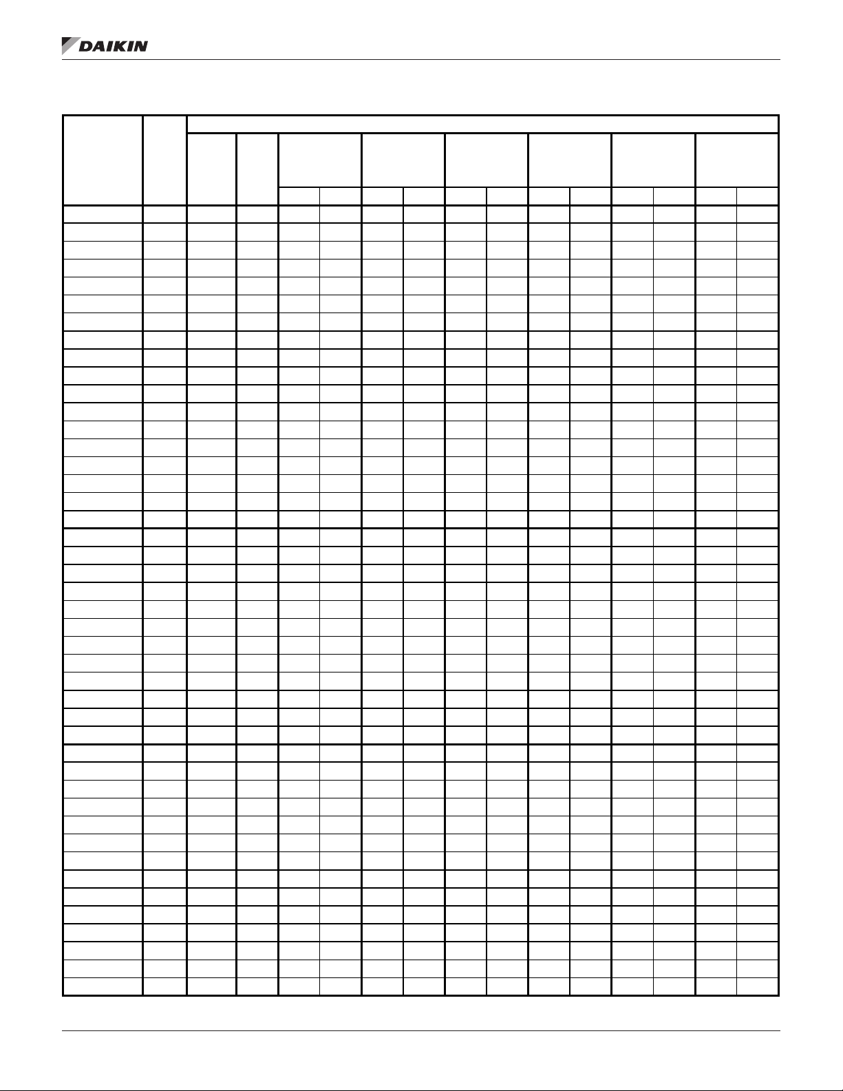
Table 6: Recommended Horizontal or Downow Suction Line Size
Recommended Horizontal or Downow Suction Line Size
InsTallaTIon and applICaTIon ConsIderaTIons
Model Circuit
AWS210CDH 1 105 4 1/8 3 5/8 1.47 3 5/8 2.20 4 1/8 1.59 4 1/8 1.98 4 1/8 2.38 4 1/8 2.86
AWS210CDH 2 105 4 1/8 3 5/8 1.47 3 5/8 2.20 4 1/8 1.59 4 1/8 1.98 4 1/8 2.38 4 1/8 2.86
AWS230CDH 1 105 4 1/8 3 5/8 1.47 3 5/8 2.20 4 1/8 1.59 4 1/8 1.98 4 1/8 2.38 4 1/8 2.86
AWS230CDH 2 125 4 1/8 3 5/8 2.01 4 1/8 1.63 4 1/8 2.17 4 1/8 2.71 4 1/8 3.26 4 1/8 3.91
AWS250CDH 1 125 4 1/8 3 5/8 2.01 4 1/8 1.63 4 1/8 2.17 4 1/8 2.71 4 1/8 3.26 4 1/8 3.91
AWS250CDH 2 125 4 1/8 3 5/8 2.01 4 1/8 1.63 4 1/8 2.17 4 1/8 2.71 4 1/8 3.26 4 1/8 3.91
AWS280CDH 1 125 4 1/8 3 5/8 2.01 4 1/8 1.63 4 1/8 2.17 4 1/8 2.71 4 1/8 3.26 4 1/8 3.91
AWS280CDH 2 150 4 1/8 4 1/8 1.51 4 1/8 2.26 4 1/8 3.01 5 1/8 1.33 5 1/8 1.60 5 1/8 1.92
AWS300CDH 1 150 4 1/8 4 1/8 1.51 4 1/8 2.26 4 1/8 3.01 5 1/8 1.33 5 1/8 1.60 5 1/8 1.92
AWS300CDH 2 150 4 1/8 4 1/8 1.51 4 1/8 2.26 4 1/8 3.01 5 1/8 1.33 5 1/8 1.60 5 1/8 1.92
AWS330CDH 1 150 4 1/8 4 1/8 1.51 4 1/8 2.26 4 1/8 3.01 5 1/8 1.33 5 1/8 1.60 5 1/8 1.92
AWS330CDH 2 175 4 1/8 4 1/8 1.99 4 1/8 2.98 5 1/8 1.40 5 1/8 1.76 5 1/8 2.11 5 1/8 2.53
AWS350CDH 1 175 4 1/8 4 1/8 1.99 4 1/8 2.98 5 1/8 1.40 5 1/8 1.76 5 1/8 2.11 5 1/8 2.53
AWS350CDH 2 175 4 1/8 4 1/8 1.99 4 1/8 2.98 5 1/8 1.40 5 1/8 1.76 5 1/8 2.11 5 1/8 2.53
AWS390CDH 1 175 4 1/8 4 1/8 1.99 4 1/8 2.98 5 1/8 1.40 5 1/8 1.76 5 1/8 2.11 5 1/8 2.53
AWS390CDH 2 205 4 1/8 4 1/8 2.64 5 1/8 1.40 5 1/8 1.87 5 1/8 2.33 5 1/8 2.80 5 1/8 3.36
AWS410CDH 1 205 4 1/8 4 1/8 2.64 5 1/8 1.40 5 1/8 1.87 5 1/8 2.33 5 1/8 2.80 5 1/8 3.36
AWS410CDH 2 205 4 1/8 4 1/8 2.64 5 1/8 1.40 5 1/8 1.87 5 1/8 2.33 5 1/8 2.80 5 1/8 3.36
AWS450CTH 1 150 4 1/8 4 1/8 1.51 4 1/8 2.26 4 1/8 3.01 5 1/8 1.33 5 1/8 1.60 5 1/8 1.92
AWS450CTH 2 150 4 1/8 4 1/8 1.51 4 1/8 2.26 4 1/8 3.01 5 1/8 1.33 5 1/8 1.60 5 1/8 1.92
AWS450CTH 3 150 4 1/8 4 1/8 1.51 4 1/8 2.26 4 1/8 3.01 5 1/8 1.33 5 1/8 1.60 5 1/8 1.92
AWS475CTH 1 150 4 1/8 4 1/8 1.51 4 1/8 2.26 4 1/8 3.01 5 1/8 1.33 5 1/8 1.60 5 1/8 1.92
AWS475CTH 2 150 4 1/8 4 1/8 1.51 4 1/8 2.26
AWS475CTH 3 175 4 1/8 4 1/8 1.99 4 1/8 2.98 5 1/8 1.40 5 1/8 1.76 5 1/8 2.11 5 1/8 2.53
AWS500CTH 1 175 4 1/8 4 1/8 1.99 4 1/8 2.98 5 1/8 1.40 5 1/8 1.76 5 1/8 2.11 5 1/8 2.53
AWS500CTH 2 175 4 1/8 4 1/8 1.99 4 1/8 2.98 5 1/8 1.40 5 1/8 1.76 5 1/8 2.11 5 1/8 2.53
AWS500CTH 3 150 4 1/8 4 1/8 1.51 4 1/8 2.26 4 1/8 3.01 5 1/8 1.33 5 1/8 1.60 5 1/8 1.92
AWS530CTH 1 175 4 1/8 4 1/8 1.99 4 1/8 2.98 5 1/8 1.40 5 1/8 1.76 5 1/8 2.11 5 1/8 2.53
AWS530CTH 2 175 4 1/8 4 1/8 1.99 4 1/8 2.98 5 1/8 1.40 5 1/8 1.76 5 1/8 2.11 5 1/8 2.53
AWS530CTH 3 175 4 1/8 4 1/8 1.99 4 1/8 2.98 5 1/8 1.40 5 1/8 1.76 5 1/8 2.11 5 1/8 2.53
AWS240CDP 1 105 4 1/8 3 5/8 1.47 3 5/8 2.20 4 1/8 1.59 4 1/8 1.98 4 1/8 2.38 4 1/8 2.86
AWS240CDP 2 105 4 1/8 3 5/8 1.47 3 5/8 2.20 4 1/8 1.59 4 1/8 1.98 4 1/8 2.38 4 1/8 2.86
AWS265CDP 1 105 4 1/8 3 5/8 1.47 3 5/8 2.20 4 1/8 1.59 4 1/8 1.98 4 1/8 2.38 4 1/8 2.86
AWS265CDP 2 125 4 1/8 3 5/8 2.01 4 1/8 1.63 4 1/8 2.17 4 1/8 2.71 4 1/8 3.26 4 1/8 3.91
AWS290CDP 1 125 4 1/8 3 5/8 2.01 4 1/8 1.63 4 1/8 2.17 4 1/8 2.71 4 1/8 3.26 4 1/8 3.91
AWS290CDP 2 125 4 1/8 3 5/8 2.01 4 1/8 1.63 4 1/8 2.17 4 1/8 2.71 4 1/8 3.26 4 1/8 3.91
AWS310CDP 1 125 4 1/8 3 5/8 2.01 4 1/8 1.63 4 1/8 2.17 4 1/8 2.71 4 1/8 3.26 4 1/8 3.91
AWS310CDP 2 150 4 1/8 4 1/8 1.51 4 1/8 2.26 4 1/8 3.01 5 1/8 1.33 5 1/8 1.60 5 1/8 1.92
AWS330CDP 1 150 4 1/8 4 1/8 1.51 4 1/8 2.26 4 1/8 3.01 5 1/8 1.33 5 1/8 1.60 5 1/8 1.92
AWS330CDP 2 150 4 1/8 4 1/8 1.51 4 1/8 2.26 4 1/8 3.01 5 1/8 1.33 5 1/8 1.60 5 1/8 1.92
AWS365CDP 1 150 4 1/8 4 1/8 1.51 4 1/8 2.26 4 1/8 3.01 5 1/8 1.33 5 1/8 1.60 5 1/8 1.92
AWS365CDP 2 175 4 1/8 4 1/8 1.99 4 1/8 2.98 5 1/8 1.40 5 1/8 1.76 5 1/8 2.11 5 1/8 2.53
AWS400CDP 1 175 4 1/8 4 1/8 1.99 4 1/8 2.98 5 1/8 1.40 5 1/8 1.76 5 1/8 2.11 5 1/8 2.53
AWS400CDP 2 175 4 1/8 4 1/8 1.99 4 1/8 2.98 5 1/8 1.40 5 1/8 1.76 5 1/8 2.11 5 1/8 2.53
Nominal
Tons Per
Circuit
Tubing
Conn.
Size At
Unit
UP TO 50
EQUIV. FT.
Size PD Size PD Size PD Size PD Size PD Size PD
UP TO 75
EQUIV. FT.
UP TO 100
EQUIV. FT.
4 1/8 3.01 5 1/8 1.33 5 1/8 1.60 5 1/8 1.92
UP TO 125
EQUIV. FT.
UP TO 150
EQUIV. FT.
UP TO 180
EQUIV. FT.
IM 1203-1 • PATHFINDER® MODEL AWS REMOTE CHILLERS 10 www.DaikinApplied.com
Page 13
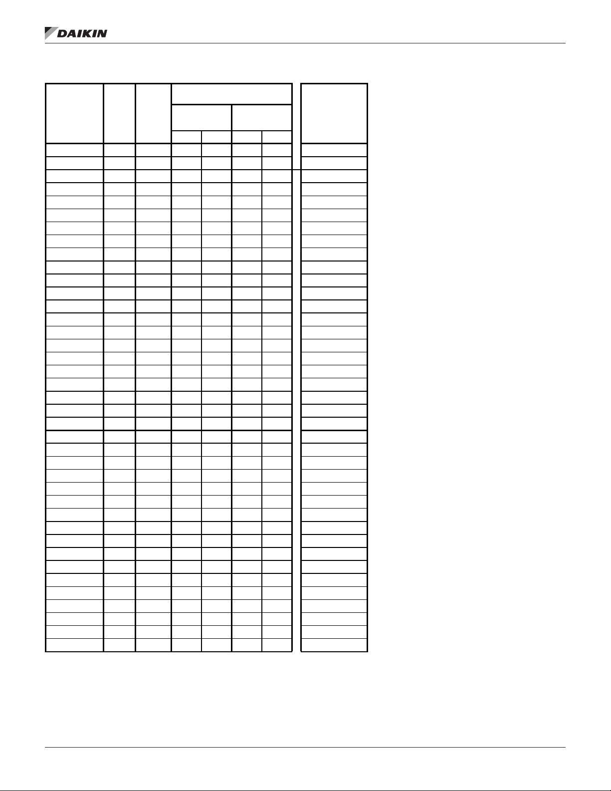
Table 7: Recommended Upow Suction
Recommended Vertical or Upow
Model Circuit
AWS170CDS 1 95 3 5/8 1.23 3 5/8 1.84 3 5/8
AWS170CDS 2 95 3 5/8 1.23 3 5/8 1.84 3 5/8
AWS190CDS 1 95 3 5/8 1.23 3 5/8 1.84 3 5/8
AWS190CDS 2 95 3 5/8 1.23 3 5/8 1.84 3 5/8
AWS200CDS 1 11 5 3 5/8 1.73 3 5/8 2.60 3 5/8
AWS200CDS 2 11 5 3 5/8 1.73 3 5/8 2.60 3 5/8
AWS210CDS 1 95 3 5/8 1.23 3 5/8 1.84 3 5/8
AWS210CDS 2 11 5 3 5/8 1.73 3 5/8 2.60 3 5/8
AWS225CDS 1 11 5 3 5/8 1.73 3 5/8 2.60 3 5/8
AWS225CDS 2 11 5 3 5/8 1.73 3 5/8 2.60 3 5/8
AWS250CDS 1 11 5 3 5/8 1.73 3 5/8 2.60 3 5/8
AWS250CDS 2 135 4 1/8 1.25 4 1/8 1.87 4 1/8
AWS260CDS 1 135 4 1/8 1.25 4 1/8 1.87 4 1/8
AWS260CDS 2 135 4 1/8 1.25 4 1/8 1.87 4 1/8
AWS290CDS 1 135 4 1/8 1.25 4 1/8 1.87 4 1/8
AWS290CDS 2 155 4 1/8 1.60 4 1/8 2.40 4 1/8
AWS310CDS 1 155 4 1/8 1.60 4 1/8 2.40 4 1/8
AWS310CDS 2 155 4 1/8 1.60 4 1/8 2.40 4 1/8
AWS350CDS 1 155 4 1/8 1.60 4 1/8 2.40 4 1/8
AWS350CDS 2 185 4 1/8 2.20 4 1/8 3.30 4 1/8
AWS375CDS 1 185 4 1/8 2.20 4 1/8 3.30 4 1/8
AWS375CDS 2 185 4 1/8 2.20 4 1/8 3.30 4 1/8
AWS400CTS 1 135 4 1/8 1.25 4 1/8 1.87 4 1/8
AWS400CTS 2 135 4 1/8 1.25 4 1/8 1.87 4 1/8
AWS400CTS 3 135 4 1/8 1.25 4 1/8 1.87 4 1/8
AWS425CTS 1 135 4 1/8 1.25 4 1/8 1.87 4 1/8
AWS425CTS 2 135 4 1/8 1.25 4 1/8 1.87 4 1/8
AWS425CTS 3 155 4 1/8 1.60 4 1/8 2.40 4 1/8
AWS450CTS 1 155 4 1/8 1.60 4 1/8 2.40 4 1/8
AWS450CTS 2 155 4 1/8 1.60 4 1/8 2.40 4 1/8
AWS450CTS 3 135 4 1/8 1.25 4 1/8 1.87 4 1/8
AWS470CTS 1 155 4 1/8 1.60 4 1/8 2.40 4 1/8
AWS470CTS 2 155 4 1/8 1.60 4 1/8 2.40 4 1/8
AWS470CTS 3 155 4 1/8 1.60 4 1/8 2.40 4 1/8
AWS500CTS 1 155 4 1/8 1.60 4 1/8 2.40 4 1/8
AWS500CTS 2 155 4 1/8 1.60 4 1/8 2.40 4 1/8
AWS500CTS 3 185 4 1/8 2.20 4 1/8 3.30 4 1/8
AWS525CTS 1 185 4 1/8 2.20 4 1/8 3.30 4 1/8
AWS525CTS 2 185 4 1/8 2.20 4 1/8 3.30 4 1/8
Nominal
Tons Per
Circuit
Suction Line Size
UP TO 50
EQUIV. FT.
Size PD Size PD
UP TO 75
EQUIV. FT.
Max. Suct. Riser
Line Size for
Vertical Upow
to Compressor
InsTallaTIon and applICaTIon ConsIderaTIons
www.DaikinApplied.com 11 IM 1203-1 • PATHFINDER® MODEL AWS REMOTE CHILLERS
Page 14
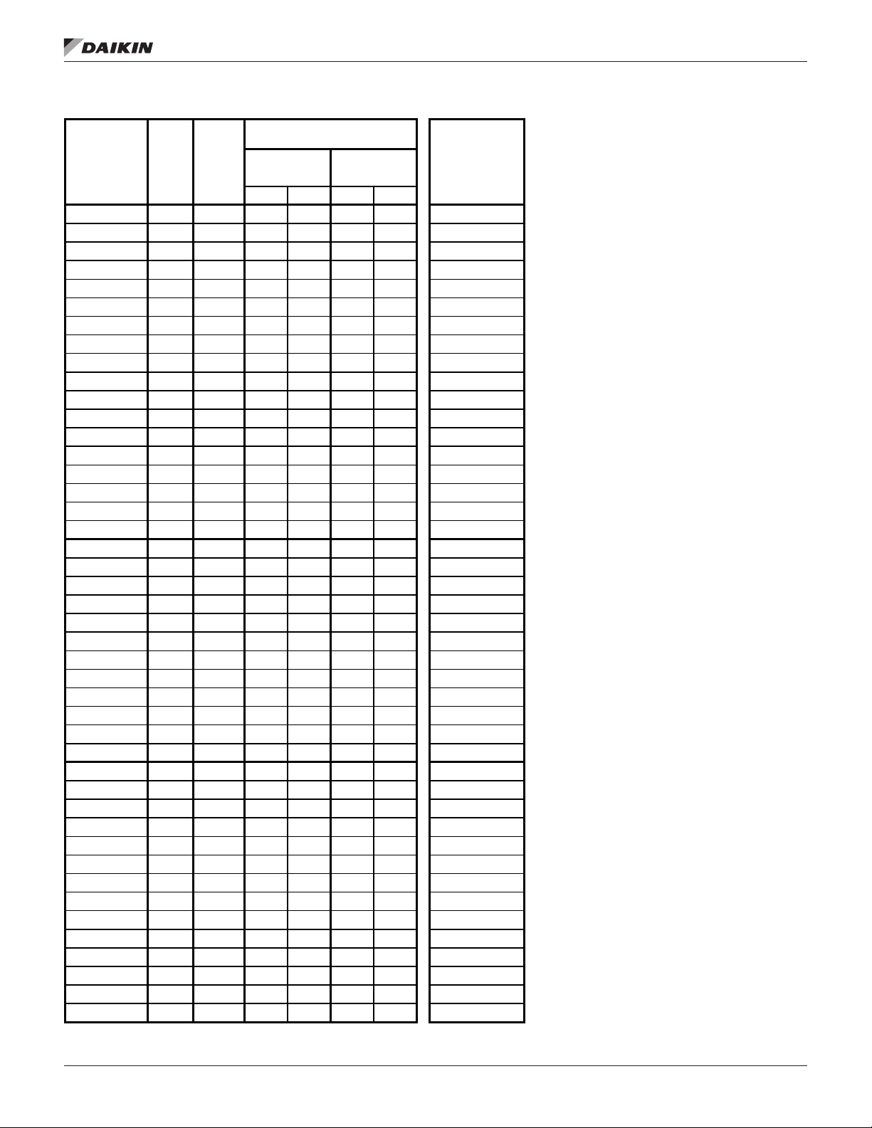
Table 6 continued: Recommended Upow Suction
Recommended Vertical or Upow
Model Circuit
AWS210CDH 1 105 3 5/8 1.47 3 5/8 2.20 3 5/8
AWS210CDH 2 105 3 5/8 1.47 3 5/8 2.20 3 5/8
AWS230CDH 1 105 3 5/8 1.47 3 5/8 2.20 3 5/8
AWS230CDH 2 125 3 5/8 2.01 3 5/8 3.02 3 5/8
AWS250CDH 1 125 3 5/8 2.01 3 5/8 3.02 3 5/8
AWS250CDH 2 125 3 5/8 2.01 3 5/8 3.02 3 5/8
AWS280CDH 1 125 3 5/8 2.01 3 5/8 3.02 3 5/8
AWS280CDH 2 150 4 1/8 1.51 4 1/8 2.26 4 1/8
AWS300CDH 1 150 4 1/8 1.51 4 1/8 2.26 4 1/8
AWS300CDH 2 150 4 1/8 1.51 4 1/8 2.26 4 1/8
AWS330CDH 1 150 4 1/8 1.51 4 1/8 2.26 4 1/8
AWS330CDH 2 175 4 1/8 1.99 4 1/8 2.98 4 1/8
AWS350CDH 1 175 4 1/8 1.99 4 1/8 2.98 4 1/8
AWS350CDH 2 175 4 1/8 1.99 4 1/8 2.98 4 1/8
AWS390CDH 1 175 4 1/8 1.99 4 1/8 2.98 4 1/8
AWS390CDH 2 205 4 1/8 2.64 4 1/8 3.97 4 1/8
AWS410CDH 1 205 4 1/8 2.64 4 1/8 3.97 4 1/8
AWS410CDH 2 205 4 1/8 2.64 4 1/8 3.97 4 1/8
AWS450CTH 1 150 4 1/8 1.51 4 1/8 2.26 4 1/8
AWS450CTH 2 150 4 1/8 1.51 4 1/8 2.26 4 1/8
AWS450CTH 3 150 4 1/8 1.51 4 1/8 2.26 4 1/8
AWS475CTH 1 150 4 1/8 1.51 4 1/8 2.26 4 1/8
AWS475CTH 2 150 4 1/8 1.51 4 1/8 2.26 4 1/8
AWS475CTH 3 175 4 1/8 1.99 4 1/8 2.98 4 1/8
AWS500CTH 1 175 4 1/8 1.99 4 1/8 2.98 4 1/8
AWS500CTH 2 175 4 1/8 1.99 4 1/8 2.98 4 1/8
AWS500CTH 3 150 4 1/8 1.51 4 1/8 2.26 4 1/8
AWS530CTH 1 175 4 1/8 1.99 4 1/8 2.98 4 1/8
AWS530CTH 2 175 4 1/8 1.99 4 1/8 2.98 4 1/8
AWS530CTH 3 175 4 1/8 1.99 4 1/8 2.98 4 1/8
AWS240CDP 1 105 3 5/8 1.47 3 5/8 2.20 3 5/8
AWS240CDP 2 105 3 5/8 1.47 3 5/8 2.20 3 5/8
AWS265CDP 1 105 3 5/8 1.47 3 5/8 2.20 3 5/8
AWS265CDP 2 125 3 5/8 2.01 3 5/8 3.02 3 5/8
AWS290CDP 1 125 3 5/8 2.01 3 5/8 3.02 3 5/8
AWS290CDP 2 125 3 5/8 2.01 3 5/8 3.02 3 5/8
AWS310CDP 1 125 3 5/8 2.01 3 5/8 3.02 3 5/8
AWS310CDP 2 150 4 1/8 1.51 4 1/8 2.26 4 1/8
AWS330CDP 1 150 4 1/8 1.51 4 1/8 2.26 4 1/8
AWS330CDP 2 150 4 1/8 1.51 4 1/8 2.26 4 1/8
AWS365CDP 1 150 4 1/8 1.51 4 1/8 2.26 4 1/8
AWS365CDP 2 175 4 1/8 1.99 4 1/8 2.98 4 1/8
AWS400CDP 1 175 4 1/8 1.99 4 1/8 2.98 4 1/8
AWS400CDP 2 175 4 1/8 1.99 4 1/8 2.98 4 1/8
Nominal
Tons Per
Circuit
Suction Line Size
UP TO 50
EQUIV. FT.
Size PD Size PD
UP TO 75
EQUIV. FT.
Max. Suct. Riser
Line Size for
Vertical Upow
to Compressor
InsTallaTIon and applICaTIon ConsIderaTIons
IM 1203-1 • PATHFINDER® MODEL AWS REMOTE CHILLERS 12 www.DaikinApplied.com
Page 15
InsTallaTIon and applICaTIon ConsIderaTIons
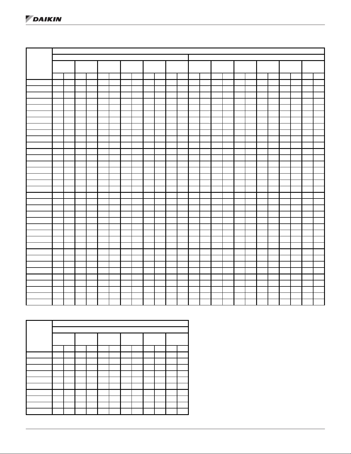
Table 8: Recommended Liquid Line Sizes (Circuits 1 & 2; Circuit 3 below)
Recommended Liquid Line Size
Circuit 1 Circuit 2
Model
AWS170CDS 1 5/8 0.70 1 5/8 1.05 1 5/8 1.41 1 5/8 1.76 1 5/8 2.11 1 5/8 2.53 1 5/8 0.70 1 5/8 1.05 1 5/8 1.41 1 5/8 1.76 1 5/8 2.11 1 5/8 2.53
AWS190CDS 1 5/8 0.70 1 5/8 1.05 1 5/8 1.41 1 5/8 1.76 1 5/8 2.11 1 5/8 2.53 1 5/8 0.70 1 5/8 1.05 1 5/8 1.41 1 5/8 1.76 1 5/8 2.11 1 5/8 2.53
AWS200CDS 1 5/8 0.99 1 5/8 1.49 1 5/8 1.98 1 5/8 2.48 1 5/8 2.98 1 5/8 3.57 1 5/8 0.99 1 5/8 1.49 1 5/8 1.98 1 5/8 2.48 1 5/8 2.98 1 5/8 3.57
AWS210CDS 1 5/8 0.70 1 5/8 1.05 1 5/8 1.41 1 5/8 1.76 1 5/8 2.11 1 5/8 2.53 1 5/8 0.99 1 5/8 1.49 1 5/8 1.98 1 5/8 2.48 1 5/8 2.98 1 5/8 3.57
AWS225CDS 1 5/8 0.99 1 5/8 1.49 1 5/8 1.98 1 5/8 2.48 1 5/8 2.98 1 5/8 3.57 1 5/8 0.99 1 5/8 1.49 1 5/8 1.98 1 5/8 2.48 1 5/8 2.98 1 5/8 3.57
AWS250CDS 1 5/8 0.99 1 5/8 1.49 1 5/8 1.98 1 5/8 2.48 1 5/8 2.98 1 5/8 3.57 1 5/8 1.32 1 5/8 1.99 1 5/8 2.65 1 5/8 3.31 1 5/8 3.97 1 5/8 4.77
AWS260CDS 1 5/8 1.32 1 5/8 1.99 1 5/8 2.65 1 5/8 3.31 1 5/8 3.97 1 5/8 4.77 1 5/8 1.32 1 5/8 1.99 1 5/8 2.65 1 5/8 3.31 1 5/8 3.97 1 5/8 4.77
AWS290CDS 1 5/8 1.32 1 5/8 1.99 1 5/8 2.65 1 5/8 3.31 1 5/8 3.97 1 5/8 4.77 1 5/8 1.70 2 1/8 0.69 2 1/8 0.91 2 1/8 1.14 2 1/8 1.37 2 1/8 1.64
AWS310CDS 1 5/8 1.70 2 1/8 0.69 2 1/8 0.91 2 1/8 1.14 2 1/8 1.37 2 1/8 1.64 1 5/8 1.70 2 1/8 0.69 2 1/8 0.91 2 1/8 1.14 2 1/8 1.37 2 1/8 1.64
AWS350CDS 1 5/8 1.70 2 1/8 0.69 2 1/8 0.91 2 1/8 1.14 2 1/8 1.37 2 1/8 1.64 1 5/8 2.33 2 1/8 0.94 2 1/8 1.26 2 1/8 1.57 2 1/8 1.88 2 1/8 2.26
AWS375CDS 1 5/8 2.33 2 1/8 0.94 2 1/8 1.26 2 1/8 1.57 2 1/8 1.88 2 1/8 2.26 1 5/8 2.33 2 1/8 0.94 2 1/8 1.26 2 1/8 1.57 2 1/8 1.88 2 1/8 2.26
AWS400CTS 1 5/8 1.32 1 5/8 1.99 1 5/8 2.65 1 5/8 3.31 1 5/8 3.97 1 5/8 4.77 1 5/8 1.32 1 5/8 1.99 1 5/8 2.65 1 5/8 3.31 1 5/8 3.97 1 5/8 4.77
AWS425CTS 1 5/8 1.32 1 5/8 1.99 1 5/8 2.65 1 5/8 3.31 1 5/8 3.97 1 5/8 4.77 1 5/8 1.32 1 5/8 1.99 1 5/8 2.65 1 5/8 3.31 1 5/8 3.97 1 5/8 4.77
AWS450CTS 1 5/8 1.70 2 1/8 0.69 2 1/8 0.91 2 1/8 1.14 2 1/8 1.37
AWS470CTS 1 5/8 1.70 2 1/8 0.69 2 1/8 0.91 2 1/8 1.14 2 1/8 1.37 2 1/8 1.64 1 5/8 1.70 2 1/8 0.69 2 1/8 0.91 2 1/8 1.14 2 1/8 1.37 2 1/8 1.64
AWS500CTS 1 5/8 1.70 2 1/8 0.69 2 1/8 0.91 2 1/8 1.14 2 1/8 1.37 2 1/8 1.64 1 5/8 1.70 2 1/8 0.69 2 1/8 0.91 2 1/8 1.14 2 1/8 1.37 2 1/8 1.64
AWS525CTS 1 5/8 2.33 2 1/8 0.94 2 1/8 1.26 2 1/8 1.57 2 1/8 1.88 2 1/8 2.26 1 5/8 2.33 2 1/8 0.94 2 1/8 1.26 2 1/8 1.57 2 1/8 1.88 2 1/8 2.26
AWS550CTS 1 5/8 2.33 2 1/8 0.94 2 1/8 1.26 2 1/8 1.57 2 1/8 1.88 2 1/8 2.26 1 5/8 2.33 2 1/8 0.94 2 1/8 1.26 2 1/8 1.57 2 1/8 1.88 2 1/8 2.26
AWS210CDH 1 5/8 0.84 1 5/8 1.26 1 5/8 1.68 1 5/8 2.11 1 5/8 2.53 1 5/8 3.03 1 5/8 0.84 1 5/8 1.26 1 5/8 1.68 1 5/8 2.11 1 5/8 2.53 1 5/8 3.03
AWS230CDH 1 5/8 0.84 1 5/8 1.26 1 5/8 1.68 1 5/8 2.11 1 5/8 2.53 1 5/8 3.03 1 5/8 1.15 1 5/8 1.73 1 5/8 2.31 1 5/8 2.88 1 5/8 3.46 1 5/8 4.15
AWS250CDH 1 5/8 1.15 1 5/8 1.73 1 5/8 2.31 1 5/8 2.88 1 5/8 3.46 1 5/8 4.15 1 5/8 1.15 1 5/8 1.73 1 5/8 2.31 1 5/8 2.88 1 5/8 3.46 1 5/8 4.15
AWS280CDH 1 5/8 1.15 1 5/8 1.73 1 5/8 2.31 1 5/8 2.88 1 5/8 3.46 1 5/8 4.15 1 5/8 1.60 1 5/8 2.40 1 5/8 3.20 1 5/8 4.00 1 5/8 4.80 1 5/8 5.76
AWS300CDH 1 5/8 1.60 1 5/8 2.40 1 5/8 3.20 1 5/8 4.00 1 5/8 4.80 1 5/8 5.76 1 5/8 1.60 1 5/8 2.40 1 5/8 3.20 1 5/8 4.00 1 5/8 4.80 1 5/8 5.76
AWS330CDH 1 5/8 1.60 1 5/8 2.40 1 5/8 3.20 1 5/8 4.00 1 5/8 4.80 1 5/8 5.76 1 5/8 2.11 2 1/8 0.85 2 1/8 1.14 2 1/8 1.42 2 1/8 1.70 2 1/8 2.05
AWS350CDH 1 5/8 2.11 2 1/8 0.85 2 1/8 1.14 2 1/8 1.42 2 1/8 1.70 2 1/8 2.05 1 5/8 2.11 2 1/8 0.85 2 1/8 1.14 2 1/8 1.42 2 1/8 1.70 2 1/8 2.05
AWS390CDH 1 5/8 2.11 2 1/8 0.85 2 1/8 1.14 2 1/8 1.42 2 1/8 1.70 2 1/8 2.05 1 5/8 2.81 2 1/8 1.13 2 1/8 1.51 2 1/8 1.89 2 1/8 2.27 2 1/8 2.72
AWS410CDH 1 5/8 2.81 2 1/8 1.13 2 1/8 1.51 2 1/8 1.89 2 1/8 2.27 2 1/8 2.72 1 5/8 2.81 2 1/8 1.13 2 1/8 1.51 2 1/8 1.89 2 1/8 2.27 2 1/8 2.72
AWS450CTH 1 5/8 1.60 1 5/8 2.40 1 5/8 3.20 1 5/8 4.00 1 5/8 4.80 1 5/8 5.76 1 5/8 1.60 1 5/8 2.40 1 5/8 3.20 1 5/8 4.00 1 5/8 4.80 1 5/8 5.76
AWS475CTH 1 5/8 1.60 1 5/8 2.40 1 5/8 3.20 1 5/8 4.00 1 5/8 4.80 1 5/8 5.76 1 5/8 1.60 1 5/8 2.40 1 5/8 3.20 1 5/8 4.00 1 5/8 4.80 1 5/8 5.76
AWS500CTH 1 5/8 2.11 2 1/8 0.85 2 1/8 1.14 2 1/8 1.42 2 1/8 1.70
AWS530CTH 1 5/8 2.11 2 1/8 0.85 2 1/8 1.14 2 1/8 1.42 2 1/8 1.70 2 1/8 2.05 1 5/8 2.11 2 1/8 0.85 2 1/8 1.14 2 1/8 1.42 2 1/8 1.70 2 1/8 2.05
AWS240CDP 1 5/8 0.84 1 5/8 1.26 1 5/8 1.68 1 5/8 2.11 1 5/8 2.53 1 5/8 3.03 1 5/8 0.84 1 5/8 1.26 1 5/8 1.68 1 5/8 2.11 1 5/8 2.53 1 5/8 3.03
AWS265CDP 1 5/8 0.84 1 5/8 1.26 1 5/8 1.68 1 5/8 2.11 1 5/8 2.53 1 5/8 3.03 1 5/8 1.15 1 5/8 1.73 1 5/8 2.31 1 5/8 2.88 1 5/8 3.46 1 5/8 4.15
AWS290CDP 1 5/8 1.15 1 5/8 1.73 1 5/8 2.31 1 5/8 2.88 1 5/8 3.46 1 5/8 4.15 1 5/8 1.15 1 5/8 1.73 1 5/8 2.31 1 5/8 2.88 1 5/8 3.46 1 5/8 4.15
AWS310CDP 1 5/8 1.15 1 5/8 1.73 1 5/8 2.31 1 5/8 2.88 1 5/8 3.46 1 5/8 4.15 1 5/8 1.60 1 5/8 2.40 1 5/8 3.20 1 5/8 4.00 1 5/8 4.80 1 5/8 5.76
AWS330CDP 1 5/8 1.60 1 5/8 2.40 1 5/8 3.20 1 5/8 4.00 1 5/8 4.80 1 5/8 5.76 1 5/8 1.60 1 5/8 2.40 1 5/8 3.20 1 5/8 4.00 1 5/8 4.80 1 5/8 5.76
UP TO 50
EQUIV. FT.
Size PD Size PD Size PD Size PD Size PD Size PD Size PD Size PD Size PD Size PD Size PD Size PD
UP TO 75
EQUIV. FT.
UP TO 100
EQUIV. FT.
UP TO 125
EQUIV. FT.
UP TO 150
EQUIV. FT.
UP TO 180
EQUIV. FT.
2 1/8 1.64 1 5/8 1.70 2 1/8 0.69 2 1/8 0.91 2 1/8 1.14 2 1/8 1.37 2 1/8 1.64
2 1/8 2.05 1 5/8 2.11 2 1/8 0.85 2 1/8 1.14 2 1/8 1.42 2 1/8 1.70 2 1/8 2.05
UP TO 50
EQUIV. FT.
UP TO 75
EQUIV. FT.
UP TO 100
EQUIV. FT.
UP TO 125
EQUIV. FT.
UP TO 150
EQUIV. FT.
UP TO 180
EQUIV. FT.
Table 9: Recommended Liquid Line Sizes (Circuit 3; only 3-circuit models shown)
Recommended Liquid Line Size
Circuit 3
Model
AWS400CTS 1 5/8 1.32 1 5/8 1.99 1 5/8 2.65 1 5/8 3.31 1 5/8 3.97 1 5/8 4.77
AWS425CTS 1 5/8 1.70 2 1/8 0.69 2 1/8 0.91 2 1/8 1.14 2 1/8 1.37 2 1/8 1.64
AWS450CTS 1 5/8 1.32 1 5/8 1.99 1 5/8 2.65 1 5/8 3.31 1 5/8 3.97 1 5/8 4.77
AWS470CTS 1 5/8 1.70 2 1/8 0.69 2 1/8 0.91 2 1/8 1.14 2 1/8 1.37 2 1/8 1.64
AWS500CTS 1 5/8 2.33 2 1/8 0.94 2 1/8 1.26 2 1/8 1.57 2 1/8 1.88 2 1/8 2.26
AWS550CTS 1 5/8 2.33 2 1/8 0.94 2 1/8 1.26 2 1/8 1.57 2 1/8 1.88 2 1/8 2.26
AWS450CTH 1 5/8 1.60 1 5/8 2.40 1 5/8 3.20 1 5/8 4.00 1 5/8 4.80 1 5/8 5.76
AWS475CTH 1 5/8 2.11 2 1/8 0.85 2 1/8 1.14 2 1/8 1.42 2 1/8 1.70 2 1/8 2.05
AWS500CTH 1 5/8 1.60 1 5/8 2.40 1 5/8 3.20 1 5/8 4.00 1 5/8 4.80 1 5/8 5.76
AWS530CTH 1 5/8 2.11 2 1/8 0.85 2 1/8 1.14 2 1/8 1.42 2 1/8 1.70 2 1/8 2.05
UP TO 50
EQUIV. FT.
Size PD Size PD Size PD Size PD Size PD Size PD
UP TO 75
EQUIV. FT.
UP TO 100
EQUIV. FT.
UP TO 125
EQUIV. FT.
UP TO 150
EQUIV. FT.
UP TO 180
EQUIV. FT.
www.DaikinApplied.com 13 IM 1203-1 • PATHFINDER® MODEL AWS REMOTE CHILLERS
Page 16
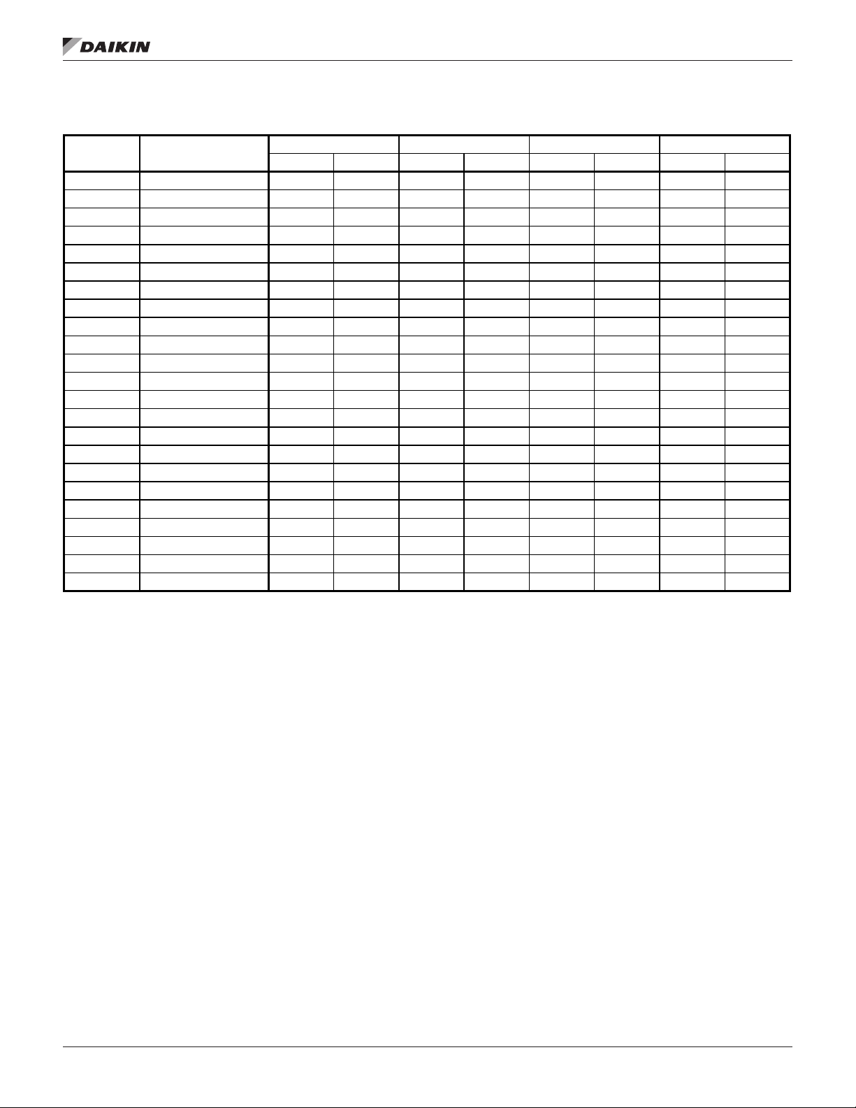
Table 10: Evaporator Data for VFD Models
remoTe evaporaTor dImensIons
remoTe evaporaTor dImensIons
AWS Model Evap Model
170CDS EV40271010/9N2 or N3 1197 543 1761 799 67 255 3 1
190CDS EV40271010/9N2 or N3 1197 543 1761 799 67 255 3 1
200CDS EV40271212/7N2 or N3 1239 562 1770 803 63 240 3 1
210CDH EV40271111/7N2 or N3 1219 553 1773 804 66 250 3 1
230CDH EV40271212/7N2 or N3 1239 562 1770 803 63 240 3 1
250CDH EV40271212/7N2 or N3 1239 562 1770 803 63 240 3 1
280CDH EV50271414/7N2 or N3 1739 789 2631 1193 106 403 4 2
300CDH EV50271414/7N2 or N3 1739 789 2631 1193 106 403 4 2
330CDH EV50271717/5N2 or N3 1819 825 2648 1201 99 374 5 2
350CDH EV50271717/5N2 or N3 1819 825 2648 1201 99 374 5 2
390CDH EV50271717/5N2 or N3 1819 825 2648 1201 99 374 5 2
410CDH EV50271717/5N2 or N3 1819 825 2648 1201 99 374 5 2
450CTH EV6633101010/7N2 or N3 2630 1193 4510 2046 225 850 7 3
475CTH EV6633111111/5N2 or N3 2681 1216 4520 2050 220 831 7 3
500CTH EV6633111111/5N2 or N3 2681 1216 4520 2050 220 831 7 3
530CTH EV6633111111/5N2 or N3 2681 1216 4520 2050 220 831 7 3
240CDP EV50391313/11N2 or N3 2008 9 11 3296 1495 154 582 5 2
265CDP EV50391313/11N2 or N3 2008 9 11 3296 1495 154 582 5 2
290CDP EV66391414/11N2 or N3 2875 1304 5145 2334 271 1027 7 3
310CDP EV66391414/11N2 or N3 2875 1304 5145 2334 271 1027 7 3
330CDP EV66391717/7N2 or N3 2998 1360 5164 2342 259 979 9 4
365CDP EV66391717/7N2 or N3 2998 1360 5164 2342 259 979 9 4
400CDP EV66391717/7N2 or N3 2998 1360 5164 2342 259 979 9 4
Shipping Weight Operating Weight Water Volume Refrigerant Charge
(lb) (kg) (lb) (kg) (gal) (L) (lb) (kg)
IM 1203-1 • PATHFINDER® MODEL AWS REMOTE CHILLERS 14 www.DaikinApplied.com
Page 17
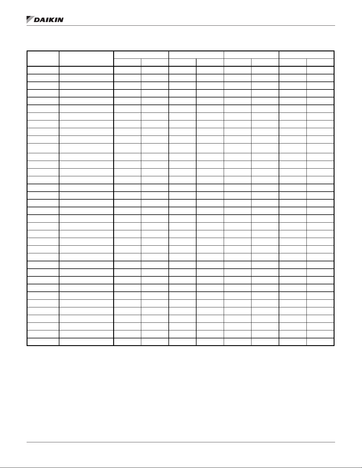
remoTe evaporaTor dImensIons
Table 11: Evaporator Data for Non-VFD Models
AWS Model Evap Model
190CDS EV40271010/9N2 or N3 1197 543 1761 799 67 255 3 1
210CDS EV40271111/7N2 or N3 1219 553 1773 804 66 250 3 1
225CDS EV40271212/7N2 or N3 1239 562 1770 803 63 240 3 1
250CDS EV40271313/5N2 or N3 1259 571 1774 805 61 232 3 2
260CDS EV40271313/5N2 or N3 1259 571 1774 805 61 232 3 2
290CDS EV50271515/5N2 or N3 1649 748 2514 1140 103 390 4 2
310CDS EV50271515/5N2 or N3 1649 748 2514 1140 103 390 4 2
350CDS EV50271717/5N2 or N3 1819 825 2648 1201 99 374 5 2
375CDS EV50271717/5N2 or N3 1819 825 2648 1201 99 374 5 2
400CTS EV6633101010/7N2 or N3 2630 1193 4510 2046 225 850 7 3
425CTS EV6633101010/7N2 or N3 2630 1193 4510 2046 225 850 7 3
450CTS EV6633101010/7N2 or N3 2630 1193 4510 2046 225 850 7 3
470CTS EV6633111111/5N2 or N3 2681 1216 4520 2050 220 831 7 3
500CTS EV6633111111/5N2 or N3 2681 1216 4520 2050 220 831 7 3
525CTS EV6633111111/5N2 or N3 2681 1216 4520 2050 220 831 7 3
550CTS EV6633111111/5N2 or N3 2681 1216 4520 2050 220 831 7 3
210CDH EV40271111/7N2 or N3 1219 553 1773 804 66 250 3 1
230CDH EV40271212/7N2 or N3 1239 562 1770 803 63 240 3 1
250CDH EV40271212/7N2 or N3 1239 562 1770 803 63 240 3 1
280CDH EV50271414/7N2 or N3 1739 789 2631 1193 106 403 4 2
300CDH EV50271414/7N2 or N3 1739 789 2631 1193 106 403 4 2
330CDH EV50271717/5N2 or N3 1819 825 2648 1201 99 374 5 2
350CDH EV50271717/5N2 or N3 1819 825 2648 1201 99 374 5 2
390CDH EV50271717/5N2 or N3 1819 825 2648 1201 99 374 5 2
410CDH EV50271717/5N2 or N3 1819 825 2648 1201 99 374 5 2
450CTH EV6633101010/7N2 or N3 2630 1193 4510 2046 225 850 7 3
475CTH EV6633111111/5N2 or N3 2681 1216 4520 2050 220 831 7 3
500CTH EV6633111111/5N2 or N3 2681 1216 4520 2050 220 831 7 3
530CTH EV6633111111/5N2 or N3 2681 1216 4520 2050 220 831 7 3
240CDP EV50391313/11N2 or N3 2008 9 11 3296 1495 154 582 5 2
265CDP EV50391313/11N2 or N3 2008 9 11 3296 1495 154 582 5 2
290CDP EV66391414/11N2 or N3 2875 1304 5145 2334 271 1027 7 3
310CDP EV66391414/11N2 or N3 2875 1304 5145 2334 271 1027 7 3
330CDP EV66391717/7N2 or N3 2998 1360 5164 2342 259 979 9 4
365CDP EV66391717/7N2 or N3 2998 1360 5164 2342 259 979 9 4
400CDP EV66391717/7N2 or N3 2998 1360 5164 2342 259 979 9 4
Shipping Weight Operating Weight Water Volume Refrigerant Charge
(lb) (kg) (lb) (kg) (gal) (L) (lb) (kg)
www.DaikinApplied.com 15 IM 1203-1 • PATHFINDER® MODEL AWS REMOTE CHILLERS
Page 18
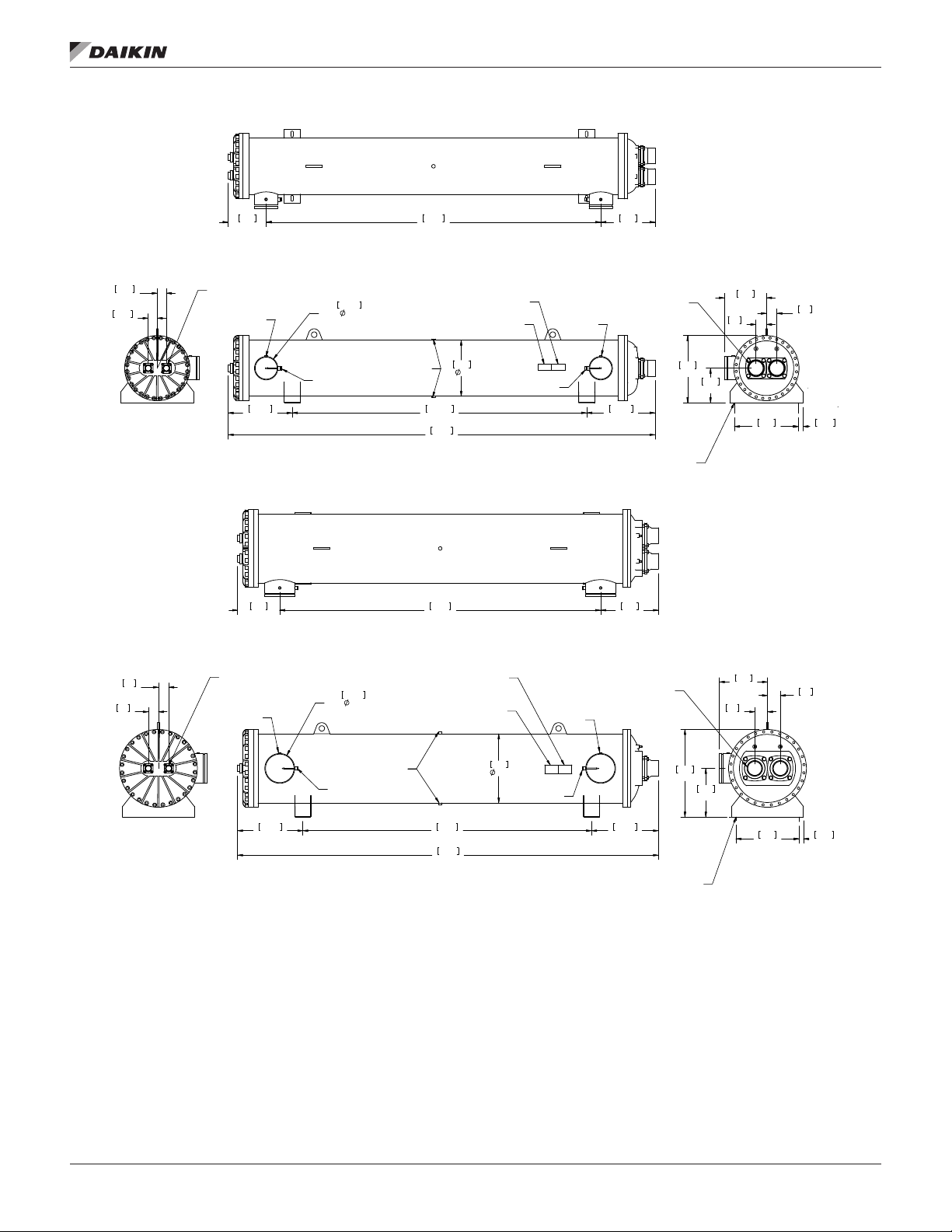
Figure 5: Evaporator Model EV4027
EVAPORATOR: EV4027
remoTe evaporaTor dImensIons
PART NO. 332532100
274
10.8
65.5
65.5
2.6
2.6
1.63IN/41.5MM I.D.
LIQUID CONNECTION
1/4" NPTF
461.6
18.2
OUTLET
Figure 6: Evaporator Model EV5027
310
12.2
168.3
6.63
SCH. 40 PIPE
VICTAULIC GROOVED QTY.2
1/2" NPTF
3000# HALF CPLG.
SENSOR WELL
QTY 2
QTY 2
2412
95.0
2122.9
83.6
3078
121.2
2360
92.9
406
16
EVAPORATOR
NAME PLATE
ASME/CRN
NAME PLATE
1/2" NPTF
QTY 2
SUCTION CONNECTION
1/4" NPTF
INTLET
.71IN/18MM X 1.69IN/43MM
392
15.4
4.13IN/105MM I.D.
493.5
19.4
SLOTS (QTY 4)
425
16.7
DWG NUMBER
334043901
303
11.9
75
3.0
485
19.1
250
9.8
EVAPORATOR: EV5027
PART NO. 332532200
DWG NUMBER
334043901
18.2
REV.
0B
75
3.0
463
REV.
0B
32.5
1.3
2123
83.6
3095
121.9
EVAPORATOR
NAME PLATE
ASME/CRN
NAME PLATE
508
20.0
1/4" NPTF
1/2" NPTF
QTY 2
4.13IN/105MM I.D.
SUCTION CONNECTION
INLET
492.2
19.4
.71IN/18MM X 1.69IN/43MM
SLOTS (QTY 4)
644
25.4
358
14.1
354
13.9
94
3.7
463
18.2
94
3.7
32.5
1.3
75
3.0
75
3.0
1.63IN/41.5MM I.D.
LIQUID CONNECTION
1/4" NPTF
479.8
18.9
219.2
8.63
SCH. 40 PIPE
VICTAULIC GROOVED QTY.2
OUTLET
1/2" NPTF
3000# HALF CPLG.
QTY 2
SENSOR WELL
QTY 2
IM 1203-1 • PATHFINDER® MODEL AWS REMOTE CHILLERS 16 www.DaikinApplied.com
Page 19
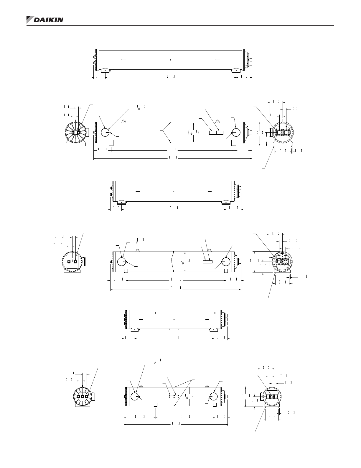
Figure 7: Evaporator Model EV5039
SLOTS (QTY 4)
SLOTS (QTY 4)
310
12.2
75
3.0
75
3.0
1.63IN/41.5MM I.D.
LIQUID CONNECTION
1/4" NPTF
OUTLET
469.8
18.5
Figure 8: Evaporator Model EV6639
367
14.4
VICTAULIC GROOVED QTY.2
SENSOR WELL
QTY 2
219.2
SCH. 40 PIPE8.63
1/2" NPTF
3000# HALF CPLG.
QTY 2
3510
138.2
3283
129.3
167.1
4245
3430
135.0
EVAPORATOR
NAME PLATE
ASME/CRN
NAME PLATE
508
20.0
1/2" NPTF
QTY 2
4.13IN/105MM I.D.
SUCTION CONNECTION
1/4" NPTF
INLET
.71IN/18MM X 1.69IN/43MM
494.5
19.5
remoTe evaporaTor dImensIons
EVAPORATOR: EV5039
PART NO. 332532300
492.2
19.4
DWG NUMBER
334043901
425
16.7
354
13.9
94
3.7
644
25.4
358
14.1
EVAPORATOR: EV6639
PART NO. 332532400
DWG NUMBER
334043901
REV.
0B
94
3.7
32.5
463
1.3
18.2
REV.
0B
2.13IN/54.1MM I.D.
105.8
105.8
4.2
4.2
LIQUID CONNECTION
1/4" NPTF
513.8
Figure 9: Evaporator Model EV6633
2.13IN/54.1MM I.D.
141
5.6
141
5.6
LIQUID CONNECTION
VICTAULIC GROOVED QTY.2
OUTLET
20.2
385.2
15.2
1/4" NPTF
273
10.75
SCH. 40 PIPE
1/2" NPTF
3000# HALF CPLG.
QTY 2
SENSOR WELL
QTY 2
VICTAULIC GROOVED QTY.2
EVAPORATOR
NAME PLATE
ASME/CRN
NAME PLATE
SENSOR WELL
QTY 2
1133.5
44.6
273
SCH. 40 PIPE
10.75
3281.8
129.2
4291.5
169.0
2829.8
111.4
146.3
3715
EVAPORATOR
NAME PLATE
ASME/CRN
NAME PLATE
660.4
26.0
660.4
26.0
2122.9
83.6
1/2" NPTF
QTY 2
1/2" NPTF
3000# HALF CPLG.
QTY 2
INLETOUTLET
1/2" NPTF
QTY 2
4.13IN/105MM I.D.
SUCTION CONNECTION
1/4" NPTF
INLET
19.5
498.7
19.6
4.13IN/105MM I.D.
SUCTION CONNECTION
1/4" NPTF
458.5
18.1
.71IN/18MM X 1.69IN/43MM
SLOTS (QTY 4)
693.5
27.3
496
.71IN/18MM X 1.69IN/43MM
EVAPORATOR: EV6633
PART NO. 332532600
DWG NUMBER
334043901
707.2
27.8
357
14.1
357
14.1
430
16.9
105.8
4.2
105.8
4.2
32.5
463
18.2
REV.
0B
430
16.9
141
5.6
463
18.2
1.3
141
5.6
32.5
1.3
www.DaikinApplied.com 17 IM 1203-1 • PATHFINDER® MODEL AWS REMOTE CHILLERS
Page 20
IsolaTor InformaTIon
IsolaTor InformaTIon
When spring isolators are required, install springs running
under the main unit supports.Then unit should be set initially
on shims or blocks at the listed spring free height. When all
unit installation tasks are complete, the springs are adjusted
upward to loosen the blocks or shims that are then removed.
Install of spring isolators requires exible piping connections
and at least three feet of exible electrical conduit to avoid
straining the piping and transmitting vibration and noise.
A rubber anti-skid pad should be used under isolators if
holddown bolts are not used. Mounting locations for each
model can be found in the Lifting & Mounting Dimensions
beginning on page 26.
Table 12: Isolator Part Numbers
Isolator Color
Brown 331481401
Dark Blue 332620200
Red 332620400 331481402
Black 332620500
Green 331481403
Dark Purple 332620600
Dark Green 332620800
Gray 332620900 331481404
White 332621000
Purple 331481405
Spring Isolator R-I-S Isolator
Isolator P/N
Table 13: Spring Isolators for Aluminum Fin Condensers (VFD)
Unit Model # Kit P/N M1 M2 M3 M4 M5 M6 M7 M8 M9 M10 M11 M12
AWS170CDS
RE VFD
AWS190CDS
RE VFD
AWS200CDS
RE VFD
AWS210CDH
RE VFD
AWS230CDH
RE VFD
AWS250CDH
RE VFD
AWS240CDP
RE VFD
AWS280CDH
RE VFD
AWS300CDH
RE VFD
AWS265CDP
RE VFD
AWS290CDP
RE VFD
AWS310CDP
RE VFD
AWS330CDP
RE VFD
AWS330CDH
RE VFD
AWS350CDH
RE VFD
AWS365CDP
RE VFD
AWS390CDH
RE VFD
AWS400CDP
RE VFD
AWS410CDH
RE VFD
AWS450CTH
RE VFD
AWS475CTH
RE VFD
AWS500CTH
RE VFD
AWS530CTH
RE VFD
332320840 Dk Green Dk Green Dk Green Dk Green Black Black Red Red
332320840 Dk Green Dk Green Dk Green Dk Green Black Black Red Red
332320840 Dk Green Dk Green Dk Green Dk Green Black Black Red Red
332320840 Dk Green Dk Green Dk Green Dk Green Black Black Red Red
332320861 Dk Green Dk Green Dk Green Dk Green Black Black Red Red Dk Blue Dk Blue
332320861 Dk Green Dk Green Dk Green Dk Green Black Black Red Red Dk Blue Dk Blue
332320862 Dk Green Dk Green Dk Green Dk Green Dk Purple Dk Purple Black Black Red Red
332320862 Dk Green Dk Green Dk Green Dk Green Dk Purple Dk Purple Black Black Red Red
332320862 Dk Green Dk Green Dk Green Dk Green Dk Purple Dk Purple Black Black Red Red
332320862 Dk Green Dk Green Dk Green Dk Green Dk Purple Dk Purple Black Black Red Red
332320862 Dk Green Dk Green Dk Green Dk Green Dk Purple Dk Purple Black Black Red Red
332320866 Dk Green Dk Green Dk Green Dk Green Dk Green Dk Green Black Black Black Black
332320866 Dk Green Dk Green Dk Green Dk Green Dk Green Dk Green Black Black Black Black
332320866 Dk Green Dk Green Dk Green Dk Green Dk Green Dk Green Black Black Black Black
332320866 Dk Green Dk Green Dk Green Dk Green Dk Green Dk Green Black Black Black Black
332320824 Dk Green Dk Green Dk Green Dk Green Dk Green Dk Green Dk Green Dk Green Dk Green Dk Green
332320824 Dk Green Dk Green Dk Green Dk Green Dk Green Dk Green Dk Green Dk Green Dk Green Dk Green
332320863 Dk Green Dk Green Dk Green Dk Green Dk Green Dk Green Dk Green Dk Green Black Black Black Black
332320863 Dk Green Dk Green Dk Green Dk Green Dk Green Dk Green Dk Green Dk Green Black Black Black Black
332320863 Dk Green Dk Green Dk Green Dk Green Dk Green Dk Green Dk Green Dk Green Black Black Black Black
332320826 Dk Green Dk Green Dk Green Dk Green Dk Green Dk Green Dk Green Dk Green Dk Green Dk Green Dk Green Dk Green
332320826 Dk Green Dk Green Dk Green Dk Green Dk Green Dk Green Dk Green Dk Green Dk Green Dk Green Dk Green Dk Green
332320826 Dk Green Dk Green Dk Green Dk Green Dk Green Dk Green Dk Green Dk Green Dk Green Dk Green Dk Green Dk Green
IM 1203-1 • PATHFINDER® MODEL AWS REMOTE CHILLERS 18 www.DaikinApplied.com
Page 21
IsolaTor InformaTIon
Table 14: Spring Isolators for Copper Fin Condensers (VFD)
Unit Model # Kit P/N M1 M2 M3 M4 M5 M6 M7 M8 M9 M10 M11 M12
AWS170CDS
RE VFD
AWS190CDS
RE VFD
AWS200CDS
RE VFD
AWS210CDH
RE VFD
AWS230CDH
RE VFD
AWS250CDH
RE VFD
AWS240CDP
RE VFD
AWS280CDH
RE VFD
AWS300CDH
RE VFD
AWS265CDP
RE VFD
AWS290CDP
RE VFD
AWS310CDP
RE VFD
AWS330CDP
RE VFD
AWS330CDH
RE VFD
AWS350CDH
RE VFD
AWS365CDP
RE VFD
AWS390CDH
RE VFD
AWS400CDP
RE VFD
AWS410CDH
RE VFD
AWS450CTH
RE VFD
AWS475CTH
RE VFD
AWS500CTH
RE VFD
AWS530CTH
RE VFD
332320864 Dk Green Dk Green Dk Green Dk Green Black Black Black Black
332320864 Dk Green Dk Green Dk Green Dk Green Black Black Black Black
332320864 Dk Green Dk Green Dk Green Dk Green Black Black Black Black
332320864 Dk Green Dk Green Dk Green Dk Green Black Black Black Black
332320865 Dk Green Dk Green Dk Green Dk Green Black Black Black Black Red Red
332320865 Dk Green Dk Green Dk Green Dk Green Black Black Black Black Red Red
332320865 Dk Green Dk Green Dk Green Dk Green Black Black Black Black Red Red
332320866 Dk Green Dk Green Dk Green Dk Green Dk Green Dk Green Black Black Black Black
332320866 Dk Green Dk Green Dk Green Dk Green Dk Green Dk Green Black Black Black Black
332320866 Dk Green Dk Green Dk Green Dk Green Dk Green Dk Green Black Black Black Black
332320866 Dk Green Dk Green Dk Green Dk Green Dk Green Dk Green Black Black Black Black
332320823 Dk Green Dk Green Dk Green Dk Green Dk Green Dk Green Dk Green Dk Green Black Black
332320823 Dk Green Dk Green Dk Green Dk Green Dk Green Dk Green Dk Green Dk Green Black Black
332320823 Dk Green Dk Green Dk Green Dk Green Dk Green Dk Green Dk Green Dk Green Black Black
332320823 Dk Green Dk Green Dk Green Dk Green Dk Green Dk Green Dk Green Dk Green Black Black
332320824 Dk Green Dk Green Dk Green Dk Green Dk Green Dk Green Dk Green Dk Green Dk Green Dk Green
332320824 Dk Green Dk Green Dk Green Dk Green Dk Green Dk Green Dk Green Dk Green Dk Green Dk Green
332320826 Dk Green Dk Green Dk Green Dk Green Dk Green Dk Green Dk Green Dk Green Dk Green Dk Green Dk Green Dk Green
332320826 Dk Green Dk Green Dk Green Dk Green Dk Green Dk Green Dk Green Dk Green Dk Green Dk Green Dk Green Dk Green
332320826 Dk Green Dk Green Dk Green Dk Green Dk Green Dk Green Dk Green Dk Green Dk Green Dk Green Dk Green Dk Green
332320826 Dk Green Dk Green Dk Green Dk Green Dk Green Dk Green Dk Green Dk Green Dk Green Dk Green Dk Green Dk Green
332320868 Gray Gray Gray Gray Gray Gray Dk Green Dk Green Dk Green Dk Green Dk Green Dk Green
332320868 Gray Gray Gray Gray Gray Gray Dk Green Dk Green Dk Green Dk Green Dk Green Dk Green
www.DaikinApplied.com 19 IM 1203-1 • PATHFINDER® MODEL AWS REMOTE CHILLERS
Page 22

IsolaTor InformaTIon
Table 15: Rubber-in-Shear (RIS) Isolators for Aluminum Fin Condensers (VFD)
Unit Model # Kit P/N M1 M2 M3 M4 M5 M6 M7 M8 M9 M10 M11 M12
AWS170CDS
RE VFD
AWS190CDS
RE VFD
AWS200CDS
RE VFD
AWS210CDH
RE VFD
AWS230CDH
RE VFD
AWS250CDH
RE VFD
AWS240CDP
RE VFD
AWS280CDH
RE VFD
AWS300CDH
RE VFD
AWS265CDP
RE VFD
AWS290CDP
RE VFD
AWS310CDP
RE VFD
AWS330CDP
RE VFD
AWS330CDH
RE VFD
AWS350CDH
RE VFD
AWS365CDP
RE VFD
AWS390CDH
RE VFD
AWS400CDP
RE VFD
AWS410CDH
RE VFD
AWS450CTH
RE VFD
AWS475CTH
RE VFD
AWS500CTH
RE VFD
AWS530CTH
RE VFD
332325851 Green Green Green Green Brown Brown Brown Brown
332325851 Green Green Green Green Brown Brown Brown Brown
332325851 Green Green Green Green Brown Brown Brown Brown
332325851 Green Green Green Green Brown Brown Brown Brown
332325852 Green Green Green Green Brown Brown Brown Brown Brown Brown
332325852 Green Green Green Green Brown Brown Brown Brown Brown Brown
332325858 Green Green Green Green Green Green Brown Brown Brown Brown
332325858 Green Green Green Green Green Green Brown Brown Brown Brown
332325858 Green Green Green Green Green Green Brown Brown Brown Brown
332325858 Green Green Green Green Green Green Brown Brown Brown Brown
332325858 Green Green Green Green Green Green Brown Brown Brown Brown
332325853 Green Green Green Green Green Green Red Red Red Red
332325853 Green Green Green Green Green Green Red Red Red Red
332325853 Green Green Green Green Green Green Red Red Red Red
332325853 Green Green Green Green Green Green Red Red Red Red
332325853 Green Green Green Green Green Green Red Red Red Red
332325853 Green Green Green Green Green Green Red Red Red Red
332325854 Green Green Green Green Green Green Green Green Red Red Red Red
332325854 Green Green Green Green Green Green Green Green Red Red Red Red
332325854 Green Green Green Green Green Green Green Green Red Red Red Red
332325854 Green Green Green Green Green Green Green Green Red Red Red Red
332325854 Green Green Green Green Green Green Green Green Red Red Red Red
332325854 Green Green Green Green Green Green Green Green Red Red Red Red
IM 1203-1 • PATHFINDER® MODEL AWS REMOTE CHILLERS 20 www.DaikinApplied.com
Page 23

IsolaTor InformaTIon
Table 16: Rubber-in-Shear (RIS) Isolators for Copper Fin Condensers (VFD)
Unit Model # Kit P/N M1 M2 M3 M4 M5 M6 M7 M8 M9 M10 M11 M12
AWS170CDS
RE VFD
AWS190CDS
RE VFD
AWS200CDS
RE VFD
AWS210CDH
RE VFD
AWS230CDH
RE VFD
AWS250CDH
RE VFD
AWS240CDP
RE VFD
AWS280CDH
RE VFD
AWS300CDH
RE VFD
AWS265CDP
RE VFD
AWS290CDP
RE VFD
AWS310CDP
RE VFD
AWS330CDP
RE VFD
AWS330CDH
RE VFD
AWS350CDH
RE VFD
AWS365CDP
RE VFD
AWS390CDH
RE VFD
AWS400CDP
RE VFD
AWS410CDH
RE VFD
AWS450CTH
RE VFD
AWS475CTH
RE VFD
AWS500CTH
RE VFD
AWS530CTH
RE VFD
332325855 Green Green Red Red Red Red Brown Brown
332325855 Green Green Red Red Red Red Brown Brown
332325855 Green Green Red Red Red Red Brown Brown
332325855 Green Green Red Red Red Red Brown Brown
332325856 Green Green Green Green Red Red Red Red Brown Brown
332325856 Green Green Green Green Red Red Red Red Brown Brown
332325856 Green Green Green Green Red Red Red Red Brown Brown
332325856 Green Green Green Green Red Red Red Red Brown Brown
332325856 Green Green Green Green Red Red Red Red Brown Brown
332325856 Green Green Green Green Red Red Red Red Brown Brown
332325856 Green Green Green Green Red Red Red Red Brown Brown
332325853 Green Green Green Green Green Green Red Red Red Red
332325853 Green Green Green Green Green Green Red Red Red Red
332325853 Green Green Green Green Green Green Red Red Red Red
332325853 Green Green Green Green Green Green Red Red Red Red
332325853 Green Green Green Green Green Green Red Red Red Red
332325853 Green Green Green Green Green Green Red Red Red Red
332325857 Gray Gray Gray Gray Green Green Green Green Green Green Red Red
332325857 Gray Gray Gray Gray Green Green Green Green Green Green Red Red
332325857 Gray Gray Gray Gray Green Green Green Green Green Green Red Red
332325857 Gray Gray Gray Gray Green Green Green Green Green Green Red Red
332325857 Gray Gray Gray Gray Green Green Green Green Green Green Red Red
332325857 Gray Gray Gray Gray Green Green Green Green Green Green Red Red
www.DaikinApplied.com 21 IM 1203-1 • PATHFINDER® MODEL AWS REMOTE CHILLERS
Page 24

IsolaTor InformaTIon
Table 17: Spring Isolators for Aluminum Fin Condensers (Non-VFD)
Unit Model # Kit P/N M1 M2 M3 M4 M5 M6 M7 M8 M9 M10
AWS190CDS 332320838 Dk Green Dk Green Dk Green Dk Green Red Red
AWS210CDS 332320838 Dk Green Dk Green Dk Green Dk Green Red Red
AWS210CDH 332320828 Dk Green Dk Green Dk Green Dk Green Black Black
AWS225CDS 332320838 Dk Green Dk Green Dk Green Dk Green Red Red
AWS230CDH 332320839 Gray Gray Dk Green Dk Green Black Black
AWS240CDP 332320840 Dk Green Dk Green Dk Green Dk Green Black Black Red Red
AWS250CDS 332320839 Gray Gray Dk Green Dk Green Black Black
AWS250CDH 332320839 Gray Gray Dk Green Dk Green Black Black
AWS260CDS 332320839 Gray Gray Dk Green Dk Green Black Black
AWS265CDP 332320854 Dk Green Dk Green Dk Green Dk Green Dk Purple Dk Purple Red Red
AWS280CDH 332320840 Dk Green Dk Green Dk Green Dk Green Black Black Red Red
AWS290CDS 332320841 Gray Gray Dk Green Dk Green Black Black Dk Blue Dk Blue
AWS290CDP 332320854 Dk Green Dk Green Dk Green Dk Green Dk Purple Dk Purple Red Red
AWS300CDH 332320840 Dk Green Dk Green Dk Green Dk Green Black Black Red Red
AWS310CDS 332320841 Gray Gray Dk Green Dk Green Black Black Dk Blue Dk Blue
AWS310CDP 332320842 Dk Green Dk Green Dk Green Dk Green Dk Green Dk Green Black Black
AWS330CDH 332320855 Gray Gray Dk Green Dk Green Dk Green Dk Green Black Black
AWS330CDP 332320842 Dk Green Dk Green Dk Green Dk Green Dk Green Dk Green Black Black
AWS350CDS 332320843 Gray Gray Dk Green Dk Green Dk Green Dk Green Red Red
AWS350CDH 332320855 Gray Gray Dk Green Dk Green Dk Green Dk Green Black Black
AWS365CDP 332320847 Gray Gray Gray Gray Dk Green Dk Green Black Black
AWS375CDS 332320843 Gray Gray Dk Green Dk Green Dk Green Dk Green Red Red
AWS390CDH 332320847 Gray Gray Gray Gray Dk Green Dk Green Black Black
AWS400CTS 332320848 Gray Gray Gray Gray Dk Green Dk Green Dk Green Dk Green
AWS400CDP 332320844 Gray Gray Gray Gray Dk Green Dk Green Black Black Red Red
AWS410CDH 332320844 Gray Gray Gray Gray Dk Green Dk Green Black Black Red Red
AWS425CTS 332320848 Gray Gray Gray Gray Dk Green Dk Green Dk Green Dk Green
AWS450CTS 332320834 Gray Gray Gray Gray Dk Green Dk Green Dk Purple Dk Purple Red Red
AWS450CTH 332320833 Gray Gray Gray Gray Dk Green Dk Green Dk Purple Dk Purple Black Black
AWS470CTS 332320834 Gray Gray Gray Gray Dk Green Dk Green Dk Purple Dk Purple Red Red
AWS475CTH 332320850 Gray Gray Gray Gray Dk Green Dk Green Dk Green Dk Green Black Black
AWS500CTS 332320850 Gray Gray Gray Gray Dk Green Dk Green Dk Green Dk Green Black Black
AWS500CTH 332320850 Gray Gray Gray Gray Dk Green Dk Green Dk Green Dk Green Black Black
AWS525CTS 332320850 Gray Gray Gray Gray Dk Green Dk Green Dk Green Dk Green Black Black
AWS530CTH 332320850 Gray Gray Gray Gray Dk Green Dk Green Dk Green Dk Green Black Black
AWS550CTS 332320850 Gray Gray Gray Gray Dk Green Dk Green Dk Green Dk Green Black Black
IM 1203-1 • PATHFINDER® MODEL AWS REMOTE CHILLERS 22 www.DaikinApplied.com
Page 25

IsolaTor InformaTIon
Table 18: Spring Isolators for Copper Fin Condensers (Non-VFD)
Unit Model # Kit P/N M1 M2 M3 M4 M5 M6 M7 M8 M9 M10
AWS190CDS 332320839 Gray Gray Dk Green Dk Green Black Black
AWS210CDS 332320839 Gray Gray Dk Green Dk Green Black Black
AWS210CDH 332320839 Gray Gray Dk Green Dk Green Black Black
AWS225CDS 332320839 Gray Gray Dk Green Dk Green Black Black
AWS230CDH 332320845 Gray Gray Dk Green Dk Green Dk Purple Dk Purple
AWS240CDP 332320857 Gray Gray Dk Green Dk Green Dk Purple Dk Purple Black Black
AWS250CDS 332320839 Gray Gray Dk Green Dk Green Black Black
AWS250CDH 332320845 Gray Gray Dk Green Dk Green Dk Purple Dk Purple
AWS260CDS 332320839 Gray Gray Dk Green Dk Green Black Black
AWS265CDP 332320855 Gray Gray Dk Green Dk Green Dk Green Dk Green Black Black
AWS280CDH 332320846 Gray Gray Dk Green Dk Green Dk Purple Dk Purple Red Red
AWS290CDS 332320846 Gray Gray Dk Green Dk Green Dk Purple Dk Purple Red Red
AWS290CDP 332320855 Gray Gray Dk Green Dk Green Dk Green Dk Green Black Black
AWS300CDH 332320846 Gray Gray Dk Green Dk Green Dk Purple Dk Purple Red Red
AWS310CDS 332320846 Gray Gray Dk Green Dk Green Dk Purple Dk Purple Red Red
AWS310CDP 332320847 Gray Gray Gray Gray Dk Green Dk Green Black Black
AWS330CDH 332320847 Gray Gray Gray Gray Dk Green Dk Green Black Black
AWS330CDP 332320847 Gray Gray Gray Gray Dk Green Dk Green Black Black
AWS350CDS 332320847 Gray Gray Gray Gray Dk Green Dk Green Black Black
AWS350CDH 332320847 Gray Gray Gray Gray Dk Green Dk Green Black Black
AWS365CDP 332320848 Gray Gray Gray Gray Dk Green Dk Green Dk Green Dk Green
AWS375CDS 332320847 Gray Gray Gray Gray Dk Green Dk Green Black Black
AWS390CDH 332320848 Gray Gray Gray Gray Dk Green Dk Green Dk Green Dk Green
AWS400CTS 332320848 Gray Gray Gray Gray Dk Green Dk Green Dk Green Dk Green
AWS400CDP 332320833 Gray Gray Gray Gray Dk Green Dk Green Dk Purple Dk Purple Black Black
AWS410CDH 332320833 Gray Gray Gray Gray Dk Green Dk Green Dk Purple Dk Purple Black Black
AWS425CTS 332320848 Gray Gray Gray Gray Dk Green Dk Green Dk Green Dk Green
AWS450CTS 332320856 White White Gray Gray Dk Green Dk Green Dk Green Dk Green Black Black
AWS450CTH 332320856 White White Gray Gray Dk Green Dk Green Dk Green Dk Green Black Black
AWS470CTS 332320856 White White Gray Gray Dk Green Dk Green Dk Green Dk Green Black Black
AWS475CTH 332320858 Gray Gray Gray Gray Dk Green Dk Green Dk Green Dk Green Dk Green Dk Green
AWS500CTS 332320859 Gray Gray Gray Gray Dk Green Dk Green Dk Green Dk Green Dk Purple Dk Purple
AWS500CTH 332320860 White White Gray Gray Gray Gray Dk Green Dk Green Dk Green Dk Green
AWS525CTS 332320860 White White Gray Gray Gray Gray Dk Green Dk Green Dk Green Dk Green
AWS530CTH 332320853 White White White White Gray Gray Dk Green Dk Green Dk Green Dk Green
AWS550CTS 332320853 White White White White Gray Gray Dk Green Dk Green Dk Green Dk Green
www.DaikinApplied.com 23 IM 1203-1 • PATHFINDER® MODEL AWS REMOTE CHILLERS
Page 26

IsolaTor InformaTIon
Table 19: Rubber-in-Shear (RIS) Isolators for Aluminum Fin Condensers (Non-VFD)
Unit Model # Kit P/N M1 M2 M3 M4 M5 M6 M7 M8 M9 M10
AWS190CDS 332325836 Green Green Red Red Brown Brown
AWS210CDS 332325836 Green Green Red Red Brown Brown
AWS210CDH 332325837 Gray Gray Green Green Brown Brown
AWS225CDS 332325837 Gray Gray Green Green Brown Brown
AWS230CDH 332325837 Gray Gray Green Green Brown Brown
AWS240CDP 332325838 Green Green Green Green Red Red Brown Brown
AWS250CDS 332325837 Gray Gray Green Green Brown Brown
AWS250CDH 332325837 Gray Gray Green Green Brown Brown
AWS260CDS 332325837 Gray Gray Green Green Brown Brown
AWS265CDP 332325838 Green Green Green Green Red Red Brown Brown
AWS280CDH 332325838 Green Green Green Green Red Red Brown Brown
AWS290CDS 332325847 Gray Gray Green Green Brown Brown Brown Brown
AWS290CDP 332325838 Green Green Green Green Red Red Brown Brown
AWS300CDH 332325838 Green Green Green Green Red Red Brown Brown
AWS310CDS 332325847 Gray Gray Green Green Brown Brown Brown Brown
AWS310CDP 332325829 Gray Gray Green Green Red Red Brown Brown
AWS330CDH 332325829 Gray Gray Green Green Red Red Brown Brown
AWS330CDP 332325829 Gray Gray Green Green Red Red Brown Brown
AWS350CDS 332325829 Gray Gray Green Green Red Red Brown Brown
AWS350CDH 332325829 Gray Gray Green Green Red Red Brown Brown
AWS365CDP 332325839 Gray Gray Green Green Red Red Red Red
AWS375CDS 332325829 Gray Gray Green Green Red Red Brown Brown
AWS390CDH 332325839 Gray Gray Green Green Red Red Red Red
AWS400CTS 332325830 Gray Gray Gray Gray Green Green Red Red
AWS400CDP 332325840 Gray Gray Green Green Red Red Brown Brown Brown Brown
AWS410CDH 332325840 Gray Gray Green Green Red Red Brown Brown Brown Brown
AWS425CTS 332325830 Gray Gray Gray Gray Green Green Red Red
AWS450CTS 332325842 Gray Gray Gray Gray Green Green Red Red Brown Brown
AWS450CTH 332325842 Gray Gray Gray Gray Green Green Red Red Brown Brown
AWS470CTS 332325842 Gray Gray Gray Gray Green Green Red Red Brown Brown
AWS475CTH 332325848 Gray Gray Gray Gray Green Green Red Red Red Red
AWS500CTS 332325842 Gray Gray Gray Gray Green Green Red Red Brown Brown
AWS500CTH 332325849 Gray Gray Gray Gray Green Green Green Green Brown Brown
AWS525CTS 332325849 Gray Gray Gray Gray Green Green Green Green Brown Brown
AWS530CTH 332325849 Gray Gray Gray Gray Green Green Green Green Brown Brown
AWS550CTS 332325849 Gray Gray Gray Gray Green Green Green Green Brown Brown
IM 1203-1 • PATHFINDER® MODEL AWS REMOTE CHILLERS 24 www.DaikinApplied.com
Page 27

IsolaTor InformaTIon
Table 20: Rubber-in-Shear (RIS) Isolators for Copper Fin Condensers (Non-VFD)
Unit Model # Kit P/N M1 M2 M3 M4 M5 M6 M7 M8 M9 M10
AWS190CDS 332325828 Gray Gray Green Green Red Red
AWS210CDS 332325828 Gray Gray Green Green Red Red
AWS210CDH 332325828 Gray Gray Green Green Red Red
AWS225CDS 332325828 Gray Gray Green Green Red Red
AWS230CDH 332325828 Gray Gray Green Green Red Red
AWS240CDP 332325829 Gray Gray Green Green Red Red Brown Brown
AWS250CDS 332325828 Gray Gray Green Green Red Red
AWS250CDH 332325841 Gray Gray Gray Gray Red Red
AWS260CDS 332325828 Gray Gray Green Green Red Red
AWS265CDP 332325829 Gray Gray Green Green Red Red Brown Brown
AWS280CDH 332325829 Gray Gray Green Green Red Red Brown Brown
AWS290CDS 332325829 Gray Gray Green Green Red Red Brown Brown
AWS290CDP 332325829 Gray Gray Green Green Red Red Brown Brown
AWS300CDH 332325829 Gray Gray Green Green Red Red Brown Brown
AWS310CDS 332325829 Gray Gray Green Green Red Red Brown Brown
AWS310CDP 332325830 Gray Gray Gray Gray Green Green Red Red
AWS330CDH 332325830 Gray Gray Gray Gray Green Green Red Red
AWS330CDP 332325830 Gray Gray Gray Gray Green Green Red Red
AWS350CDS 332325830 Gray Gray Gray Gray Green Green Red Red
AWS350CDH 332325830 Gray Gray Gray Gray Green Green Red Red
AWS365CDP 332325830 Gray Gray Gray Gray Green Green Red Red
AWS375CDS 332325830 Gray Gray Gray Gray Green Green Red Red
AWS390CDH 332325830 Gray Gray Gray Gray Green Green Red Red
AWS400CTS 332325843 Gray Gray Gray Gray Green Green Green Green
AWS400CDP 332325842 Gray Gray Gray Gray Green Green Red Red Brown Brown
AWS410CDH 332325842 Gray Gray Gray Gray Green Green Red Red Brown Brown
AWS425CTS 332325843 Gray Gray Gray Gray Green Green Green Green
AWS450CTS 332325846 Purple Purple Gray Gray Green Green Green Green Red Red
AWS450CTH 332325850 Gray Gray Gray Gray Green Green Green Green Red Red
AWS470CTS 332325846 Purple Purple Gray Gray Green Green Green Green Red Red
AWS475CTH 332325846 Purple Purple Gray Gray Green Green Green Green Red Red
AWS500CTS 332325846 Purple Purple Gray Gray Green Green Green Green Red Red
AWS500CTH 332325844 Purple Purple Gray Gray Gray Gray Green Green Red Red
AWS525CTS 332325844 Purple Purple Gray Gray Gray Gray Green Green Red Red
AWS530CTH 332325845 Purple Purple Purple Purple Gray Gray Green Green Red Red
AWS550CTS 332325845 Purple Purple Purple Purple Gray Gray Green Green Red Red
www.DaikinApplied.com 25 IM 1203-1 • PATHFINDER® MODEL AWS REMOTE CHILLERS
Page 28

Figure 10: 10 Fan Non-VFD Models
87.6
2225
7.5
190
3.9
100
600
23.6
2100
82.7
4910
193.3
5820
229.1
19
.750
TYP.
431
17.0
4791
188.6
CONTROL BOX
L1
M1M3
L3
M5
L2
M2M4
L4
M6
330974501
AWS REMOTE 10 FAN DIM DWG
2 2
lIfTIng and mounTIng loCaTIons
lIfTIng and mounTIng loCaTIons
IM 1203-1 • PATHFINDER® MODEL AWS REMOTE CHILLERS 26 www.DaikinApplied.com
Page 29

Figure 11: 12 Fan Non-VFD Models
87.6
2225
7.5
190
3.9
100
600
23.6
2100
82.7
4910
193.3
5820
229.1
431
17.0
4791
188.6
CONTROL BOX
L1
M1M3
L3
M5
L2
M2M4
L4
M6
330974502
AWS REMOTE 12 FAN DIM. DWG
3 3
lIfTIng and mounTIng loCaTIons
www.DaikinApplied.com 27 IM 1203-1 • PATHFINDER® MODEL AWS REMOTE CHILLERS
Page 30

Figure 12: 14 Fan Non-VFD Models
87.6
2225
2.6
66
7.5
190
3.9
100
0
0
17.0
431
23.6
600
82.7
2100
188.6
4791
248.4
6310
264.6
6720
CONTROL BOX
L1
M1M3
L3
M5
L2
M2M4
L4
M6
330974503
AWS REMOTE 14 FAN DIM. DWG
3 3
lIfTIng and mounTIng loCaTIons
IM 1203-1 • PATHFINDER® MODEL AWS REMOTE CHILLERS 28 www.DaikinApplied.com
Page 31

Figure 13: 16 Fan Non-VFD Models
87.6
2225
2.6
66
7.5
190
3.9
100
19
.750
TYP.
600
23.6
2100
82.7
4910
193.3
7210
283.9
7620
300.0
431
17.0
2381
93.7
4791
188.6
6791
267.4
CONTROL BOX
L1
M1M3
L3
L5
M5M7
L7
M8
L8
L6
M6
L4
M4 M2
L2
330974504
AWS REMOTE 16 FAN DIM. DWG
3 3
lIfTIng and mounTIng loCaTIons
www.DaikinApplied.com 29 IM 1203-1 • PATHFINDER® MODEL AWS REMOTE CHILLERS
Page 32

Figure 14: 18 Fan Non-VFD Models
87.6
2225
2.6
66
7.5
190
3.9
100
19
.750
TYP.
600
23.6
2100
82.7
4910
193.3
8110
319.3
8520
335.5
431
17.0
2381
93.7
4791
188.6
7484
294.6
CONTROL BOX
L1
M1M3
L3L5
M5M7
L7
M8
L8
M6
L6 L4
M4 M2
L2
330974505
AWS REMOTE 18 FAN DIM DWG.
2 2
lIfTIng and mounTIng loCaTIons
IM 1203-1 • PATHFINDER® MODEL AWS REMOTE CHILLERS 30 www.DaikinApplied.com
Page 33

Figure 15: 20 Fan Non-VFD Models
370.9
9421
23.6
600
82.7
2100
354.7
9010
87.6
2225
2.6
66
193.3
4910
7.5
190
3.9
100
16.9
430
93.7
2380
234.7
5961
330.1
8383
CONTROL BOX
L1
M1M3
L3L5
M5M7
L7
L2
M2M4
L4L6
M6M8
L8
330974506
AWS REMOTE 20 FAN DIM DWG.
3 3
lIfTIng and mounTIng loCaTIons
www.DaikinApplied.com 31 IM 1203-1 • PATHFINDER® MODEL AWS REMOTE CHILLERS
Page 34

Figure 16: 22 Fan Non-VFD Models
87.6
2225
2.6
66
7.5
190
3.9
100
10720
422.0
600
23.6
2100
82.7
6000
236.2
9110
358.7
19
.750
TYP.
430
16.9
2380
93.7
5400
212.6
8383
330.1
CONTROL BOX
L1
M1M3
L3L5
M5M7
L7
M8
L8
M6
L6 L4
M4 M2
L2
330974507
AWS REMOTE 22 FAN DIM. DWG
2 2
lIfTIng and mounTIng loCaTIons
IM 1203-1 • PATHFINDER® MODEL AWS REMOTE CHILLERS 32 www.DaikinApplied.com
Page 35

Figure 17: 24 Fan Non-VFD Models
457.5
11620
23.6
600
82.7
2100
234.2
5949
320.8
8147
413.4
10501
87.6
2225
2.6
66
7.5
190
3.9
100
19
.750
TYP.
16.9
430
93.7
2380
212.6
5400
392.2
9961
CONTROL BOX
L1
M1M3
L3L5
M5M7
L7
M9
L2
M2M4
L4L6
M6M8
L8
M10
330974508
AWS REMOTE 24 FAN DIM DWG.
2 2
lIfTIng and mounTIng loCaTIons
www.DaikinApplied.com 33 IM 1203-1 • PATHFINDER® MODEL AWS REMOTE CHILLERS
Page 36

Figure 18: 22 Fan, 3-Circuit Non-VFD Models
422.0
10718
23.6
600
82.7
2100
236.2
6000
354.3
8998
87.6
2225
2.6
66
7.5
190
3.9
100
17.0
431
93.7
2381
253.4
6438
378.6
9615
CONTROL BOX
L1L3
L4 L2
L6
L5L7
L8
M1M3
M4 M2
M6
M5M7
M8
330974509
AWS REMOTE 22-3C FAN DIM
3 3
lIfTIng and mounTIng loCaTIons
IM 1203-1 • PATHFINDER® MODEL AWS REMOTE CHILLERS 34 www.DaikinApplied.com
Page 37

Figure 19: 24 Fan, 3-Circuit Non-VFD Models
457.5
11620
23.6
600
82.7
2100
236.2
6000
413.4
10499
87.6
2225
2.6
66
7.5
190
3.9
100
318.8
8096
17.0
431
93.7
2381
253.4
6438
392.2
9962
CONTROL BOX
L1L3
L4 L2L6
L5L7
L8
M1M3
M4 M2M6
M5M7
M8
M10
M9
330974510
AWS REMOTE 24-3C FAN DIM
4 4
lIfTIng and mounTIng loCaTIons
www.DaikinApplied.com 35 IM 1203-1 • PATHFINDER® MODEL AWS REMOTE CHILLERS
Page 38

Figure 20: 26 Fan, 3-Circuit Non-VFD Models
492.9
12520
23.6
600
82.7
2100
236.2
6000
87.6
2225
7.5
190
3.9
100
318.8
8096
413.4
10501
17.0
431
93.7
2381
253.4
6438
415.9
10564
CONTROL BOX
L1
L3
L4 L2L6
L5
L7
L8
M1 M3
M4 M2M6
M5M7
M8
M10
M9
330974511
AWS REMOTE 26-3C FAN DIM
4 4
lIfTIng and mounTIng loCaTIons
IM 1203-1 • PATHFINDER® MODEL AWS REMOTE CHILLERS 36 www.DaikinApplied.com
Page 39

Figure 21: 28 Fan, 3-Circuit Non-VFD Models
528.4
13420
23.6
600
82.7
2100
236.2
6000
472.4
12000
2.6
66
7.5
190
3.9
100
354.3
9000
17.0
431
93.7
2381
253.4
6436
423.6
10761
CONTROL BOX
L1L3
L4 L2L6
L5
L7
L8
M1M3
M4 M2M6
M5
M7
M8
M10
M9
330974512
AWS REMOTE 28-3C FAN DIM
4 4
lIfTIng and mounTIng loCaTIons
www.DaikinApplied.com 37 IM 1203-1 • PATHFINDER® MODEL AWS REMOTE CHILLERS
Page 40

Figure 22: 13 Fan, 3-Circuit Non-VFD Models
563.8
14320
23.6
600
82.7
2100
236.2
6000
543.3
13800
87.6
2225
2.6
66
7.5
190
3.9
100
354.3
9000
17.0
431
93.7
2381
253.4
6436
462.5
11746
CONTROL BOX
L1L3
L4 L2L6
L5
L7
L8
M1M3
M4 M2M6
M5
M7
M8
M10
M9
330974513 4 4
AWS REMOTE 30-3C FAN DIM
lIfTIng and mounTIng loCaTIons
IM 1203-1 • PATHFINDER® MODEL AWS REMOTE CHILLERS 38 www.DaikinApplied.com
Page 41

Figure 23: 10 Fan VFD Models
610
24.0
2438
96.0
5089
200.3
M2M4L4M6L6 L2M8
PART NUMBER PART DESCRIPTIONREV.
330974530
0A
AWS REMOTE WITH VFD 10 FAN DIM. DWG
M3L3M5L 5M 7
CONTROL BOX
L1 M1
BOTTOM VIEW
.750
19
TYP.
152
143.2
3638
205.0
5208
2225
68.0
2.6
6.0
87.6
100
7.5
1727
3.9
190
66
6118
240.9
UNIT SIZE VOLTAGE HZ.
SHIPPING
WEI GHT
OPERATI NG
WEI GHT
FIN ADD
# OF
FANS
L1 L2 L3 L4 L5 L6 M1 M2 M3 M4 M5 M6 M7 M8
AWS 170CDS
380-575V 60HZ
11840 11840 1786 10 2851 2859 2085 2091 976 978 2182 2188 1743 1748 1212 1215 775 777
UNIT SIZE VOLTAGE HZ.
SHIPPING
WEI GHT
OPERATI NG
WEI GHT
FIN ADD
# OF
FANS
L1 L2 L3 L4 L5 L6 M1 M2 M3 M4 M5 M6 M7 M8
AWS 170CDS
380-575V 60HZ
5371 5371 810 10 1293 1297 946 948 443 444 990 992 791 793 550 551 352 352
AWS DIMENSI ONAL DATA - W EI GHTS I N LBS. LIFTING WEIGHT FOR EACH POINT LB
LIFTING WEIGHT FOR EACH POINT KGAWS DIMENSIONAL DATA - WEIGHTS IN KG.
MOUNTI NG LOADS FOR EACH POI NT LB
MOUNTI NG LOADS FOR EACH POI NT KG
lIfTIng and mounTIng loCaTIons
www.DaikinApplied.com 39 IM 1203-1 • PATHFINDER® MODEL AWS REMOTE CHILLERS
Page 42

Figure 24: 12 Fan VFD Models
610
24.0
2438
96.0
5089
200.3
6118
240.9
PART NUMBER PART DESCRIPTIONREV.
330974531
0A
AWS REMOTE WITH VFD 12 FAN DIM. DWG
M2L6 L4
M3 L1
M4 L2
CONTROL BOX
BOTTOM VIEW
M6
M1L3M5L5
M7
M8
87.6
TYP.
7.5
100
66
152
2.6
190
3.9
.750
19
68.0
6.0
1727
143.2
3638
2225
5208
205.0
UNIT SIZE VOLTAGE HZ.
SHIPPING
WEIGH T
OPERAT ING
WEIG HT
COPPER
FIN ADD
# OF
FAN S
L1 L2 L3 L4 L5 L6 M1 M2 M 3 M4 M5 M6 M7 M8
AWS190CDS
380-575V 60HZ
13037 13037 1786 12 3176 3062 2338 2254 1123 1083 2429 2342 1950 1880 1368 1319 890 859
AWS200CDS
380-575V 60HZ
13084 13084 1786 12 3171 3171 2310 2310 1061 1061 2428 2428 1934 1934 1336 1336 844 844
AWS210CDH
380-575V 60HZ
12288 12288 1786 12 2837 2837 2151 2151 1157 1157 2162 2162 1772 1772 1299 1299 911 911
UNIT SIZE VOLTAGE HZ.
SHIPPING
WEIGH T
OPERAT ING
WEIG HT
COPPER
FIN ADD
# OF
FAN S
L1 L2 L3 L4 L5 L6 M1 M2 M 3 M4 M5 M6 M7 M8
AWS190CDS
380-575V 60HZ
5914 5914 810 12 1441 1389 1061 1022 509 491 1102 1062 885 853 621 598 404 390
AWS200CDS
380-575V 60HZ
5935 5935 810 12 1438 1438 1048 1048 481 481 1101 1101 877 877 606 606 383 383
AWS210CDH
380-575V 60HZ
5574 5574 810 12 1287 1287 976 976 525 525 981 981 804 804 589 589 413 413
AWS D IMENSI ONAL DAT A - WEIGHT S IN LBS . LIFT ING WEIGH T FOR EAC H POIN T LB
LIFTIN G WE IGHT FOR EACH POIN T KGAWS D IMENS IONAL DAT A - WEIGHT S IN KG.
MOUN TING LOADS F OR EACH P OINT LB
MOUNTING LOADS FOR EACH POINT KG
lIfTIng and mounTIng loCaTIons
IM 1203-1 • PATHFINDER® MODEL AWS REMOTE CHILLERS 40 www.DaikinApplied.com
Page 43

Figure 25: 14 Fan VFD Models
610
24.0
2438
96.0
5089
200.3
7018
276.3
CONTROL BOX
M6L 6M 8
M9 M3 L1 M1
L4
L3M5L 5M 7
BOTTOM VIEW
M2L2M4M10
.750
1727
19
TYP.
152
68.0
143.2
3638
205.0
5208
2225
2.6
6.0
87.6
100
7.5
3.9
190
66
6608
260.2
PART NUMBER PART DESCRIPTIONREV.
330974532
0A
AWS REMOTE WITH VFD 14 FAN DIM. DWG
UN IT SIZE VOL TAGE HZ.
SHIPP ING
WEIGH T
OPER ATING
WEIGH T
COP PER
FIN A DD
# OF
FAN S
L1 L2 L 3 L4 L5 L6 M1 M2 M3 M4 M5 M6 M7 M8 M9 M10
AWS230CDH
380-575V 60HZ
13643 13643 2084 14 2834 2732 2383 2297 1729 1667 2342 2258 1889 1821 1340 1292 889 857 486 469
AWS250CDH
380-575V 60HZ
14116 14116 2084 14 2932 2932 2428 2428 1698 1698 2410 2410 1936 1936 1360 1360 887 887 465 465
UN IT SIZE VOL TAGE HZ.
SHIPP ING
WEIGH T
OPER ATING
WEIGH T
COP PER
FIN A DD
# OF
FAN S
L1 L2 L 3 L4 L5 L6 M1 M2 M3 M4 M5 M6 M7 M8 M9 M10
AWS230CDH
380-575V 60HZ
6188 6188 945 14 1285 1239 1081 1042 784 756 1062 1024 857 826 608 586 403 389 220 213
AWS250CDH
380-575V 60HZ
6403 6403 945 14 1330 1330 1101 1101 770 770 1093 1093 878 878 617 617 402 402 211 211
AWS D IMENS IONAL D ATA - WEIGH TS IN LB S. LIFTIN G WE IGHT FOR EACH POINT LB
LIF TING WEI GHT FOR EACH P OINT K GAWS DIMEN SIONAL DATA - WEIGHTS IN KG. MOUN TING L OADS FOR EACH P OINT K G
MOUN TING L OADS FOR EACH P OINT LB
lIfTIng and mounTIng loCaTIons
www.DaikinApplied.com 41 IM 1203-1 • PATHFINDER® MODEL AWS REMOTE CHILLERS
Page 44

Figure 26: 16 Fan VFD Models
610
24.0
2438
96.0
5089
200.3
7089
279.1
7918
311.7
PART NUMBER PART DESCRIPTIONREV.
330974533 0B
AWS REMOTE WITH VFD 16 FAN DIM. DWG
M8
M9
M10
L7
CONTROL BOX
L1 M1M3L3M5L 5M 7
BOTTOM VIEW
M2L2M4L4M6L6
L8
143.2
152
68.0
1727
6.0
19
5208
205.0
3638
2225
87.6
3.9
7.5
100
66
.750
190
2.6
TYP.
7508
295.6
UNIT SI ZE VOL TAGE HZ.
SHIPPING
WEIGHT
OP ERAT ING
WEIGHT
COPPER
# OF
L1 L2 L3 L4 L5 L6 L7 L8 M1 M2 M3 M4 M5 M6 M7 M8 M9 M10
AWS240CDP 14063 14063 2372 16 2775 2775 2193 2193 1350 1350 714 714 2108 2108 1792 1792 1408 1408 1093 1093 631 631
AWS280CDH
AWS300CDH
380-460V 60HZ
460V 60HZ
15233 15233 2372 16 3104 3104 2418 2418 1423 1423 672 672 2363 2363 1984 1984 1525 1525 1148 1148 596 596
UNIT SI ZE VOL TAGE HZ.
SHIPPING
WEIGHT
OP ERAT ING
WEIGHT
COPPER
FIN AD D
# OF
FANS
L1 L2 L3 L4 L5 L6 L7 L8 M1 M2 M3 M4 M5 M6 M7 M8 M9 M10
AWS240CDP 6379 6379 1076 16 1259 1259 995 995 612 612 324 324 956 956 813 813 639 639 496 496 286 286
AWS280CDH
AWS300CDH
380-460V 60HZ
460V 60HZ
6910 6910 1076 16 1408 1408 1097 1097 645 645 305 305 1072 1072 900 900 692 692 521 521 270 270
AWS DI MENSIONAL DATA - WE IGHT S IN LB S. LIF TI NG WEIGHT FO R EACH PO INT LB M OUNT ING LOADS FO R EACH POINT LB
AWS DIM ENSIONAL DAT A - WEIGHTS IN K G. LIFT ING WE IGHT FOR E ACH POINT KG M OUNT ING L OADS FOR EAC H POINT KG
lIfTIng and mounTIng loCaTIons
IM 1203-1 • PATHFINDER® MODEL AWS REMOTE CHILLERS 42 www.DaikinApplied.com
Page 45

Figure 27: 16 Fan VFD Models
410
16.1
873
34.4
1568
61.7
3348
131.8
3069
120.8
5759
226.7
5878
231.4
338.1
8589
8179
322.0
7758
305.4
L7
M10 L2 M2M4L4 M6L6M8L8
M9
L 5M 7
CONTROL BOX
L1 M1M3L3 M5
BOTTOM VIEW
87.6
190
100
66
3.9
7.5
2225
2.6
19
.750
TYP.
PART NUMBER PART DESCRIPTIONREV.
330974533 0B
AWS REMOTE W/ VFD 16 FAN DIM. DWG
UNIT SIZE VOL TAGE HZ.
SHIPPING
WEIGHT
WEIGHT
FIN ADD
# OF
FANS
L1 L 2 L3 L4 L5 L6 L 7 L8 M1 M2 M3 M4 M5 M6 M7 M8 M9 M1 0
AWS280CDH
AWS300CDH
380 60HZ
16193 16193 2372 16 3465 3480 2460 2471 1482 1489 671 674 2108 2118 1941 1950 1724 1732 1319 1325 986 991
UNIT SIZE VOL TAGE HZ.
SHIPPING
WEIGHT
WEIGHT
FIN ADD
# OF
FANS
L1 L 2 L3 L4 L5 L6 L 7 L8 M1 M2 M3 M4 M5 M6 M7 M8 M9 M1 0
AWS280CDH
AWS300CDH
380 60HZ
7345 7345 1076 16 1572 1579 1116 1121 672 675 304 306 956 961 880 885 782 786 598 601 447 450
AWS DIME NSIO NAL DAT A - WEIG HTS IN LB S. LIFT ING WEIGHT FOR EAC H POI NT L B M OUNT ING L OADS FOR EACH POINT L B
AWS DIME NSIO NAL DAT A - WEIG HTS IN KG . LIF TING WEIGHT F OR EACH POINT KG M OUNT ING LOADS FOR EACH POINT K G
lIfTIng and mounTIng loCaTIons
www.DaikinApplied.com 43 IM 1203-1 • PATHFINDER® MODEL AWS REMOTE CHILLERS
Page 46

Figure 28: 18 Fan VFD Models
96.0
2438
347.2
8818
5089
200.3
24.0
610
7782
306.4
L2M6
L6M8
M9
CONTROL BOX
L1 M1M5 L3
L4
L 5M 7
BOTTOM VIEW
M2
M3
M4
M10
.750 TYP.
19
152
6.0
1727
190
3638
143.2
68.0
5208
205.0
2225
87.6
100
7.5
3.9
66
2.6
8408
331.0
PART NUMBER PART DESCRIPTIONREV.
330974534 0A
AWS REMOTE WITH VFD 18 FAN DIM. DWG
UN IT SIZE V OLTAGE HZ.
SHIPPING
WEIGH T
OPER ATING
WEIGH T
COPPER
FIN AD D
# OF
FAN S
L1 L2 L3 L4 L5 L6 L7 L8 M1 M2 M3 M4 M5 M6 M7 M8 M9 M10
AWS265CDP
380-575V 60HZ
15250 15250 2679 18 2827 2751 2341 2278 1638 1594 923 898 2142 2084 1887 1836 1577 1534 1322 1286 803 781
AWS290CDP
380-575V 60HZ
15641 15641 2679 18 2907 2914 2389 2395 1639 1643 876 878 2204 2209 1929 1933 1595 1599 1321 1324 762 764
UN IT SIZE V OLTAGE HZ.
SHIPPING
WEIGH T
OPER ATING
WEIGH T
COPPER
FIN AD D
# OF
FAN S
L1 L2 L3 L4 L5 L6 L7 L8 M1 M2 M3 M4 M5 M6 M7 M8 M9 M10
AWS265CDP
380-575V 60HZ
6917 6917 1215 18 1282 1248 1062 1033 743 723 419 723 419 407 972 945 856 833 715 696 600 583
AWS290CDP
380-575V 60HZ
7095 7095 1215 18 1319 1322 1084 1086 743 745 397 398 1000 1002 875 877 723 725 599 601 346 347
AWS D IMENSION AL DATA - WEIGH TS IN LB S. L IFTING WE IGHT FOR E ACH POINT LB
LIFT ING WEIGHT FOR EACH POINT K GAWS D IMENSION AL DATA - WEIGH TS IN KG. MOUNTING LOADS FOR EACH POINT KG
MOUN TING LOAD S FOR EACH POINT LB
lIfTIng and mounTIng loCaTIons
IM 1203-1 • PATHFINDER® MODEL AWS REMOTE CHILLERS 44 www.DaikinApplied.com
Page 47

Figure 29: 20 Fan VFD Models
610
24.0
2438
96.0
6259
246.4
8682
341.8
9716
382.5
PART NUMBER PART DESCRIPTIONREV.
330974535 0A
AWS REMOTE WITH VFD 20 FAN DIM. DWG
M6 L2
L6 M8
M9
CONTROL BOX
L1
M3
M1
L3M5L5 M7
BOTTOM VIEW
M2
L4 M4
M10
205.0
5208
152
6.0
1727
190
3638
143.2
68.0
2225
66
87.6
TYP.
19
.750
7.5
100
3.9
2.6
9306
366.4
UNIT SIZE
VOLTAGE
SHIPPING
WEIGHT
OP ERAT ING
# OF
FANS
L1 L2 L3 L4 L 5 L6 L 7 L8 M1 M2 M3 M4 M5 M6 M7 M8 M9 M10
AWS310CDP
AWS330CDP
460V 60HZ 16486 16486 2968 20 3078 3078 2600 2600 1600 1600 966 966 2146 2146 1943 1943 1696 1696 1494 1494 965 965
UNIT SIZE
VOLTAGE
SHIPPING
WEIGHT
OP ERAT ING
# OF
FANS
L1 L2 L3 L4 L 5 L6 L 7 L8 M1 M2 M3 M4 M5 M6 M7 M8 M9 M10
AWS310CDP
AWS330CDP
460V 60HZ 7478 7478 1346 20 1396 1396 1179 1179 726 726 438 438 973 973 881 881 769 769 678 678 438 438
AWS DI ME NSIONAL DAT A - WEIGHT S IN LBS. LIFT ING WEIGHT FOR EACH POINT LB
LIFT ING WEIGHT FOR EACH POINT KGAWS DIME NSIONAL DAT A - WEIGHT S IN KG. M OUNT ING LO ADS F OR EACH POINT KG
M OUNT ING LO ADS F OR EAC H POINT LB
lIfTIng and mounTIng loCaTIons
www.DaikinApplied.com 45 IM 1203-1 • PATHFINDER® MODEL AWS REMOTE CHILLERS
Page 48

Figure 30: 20 Fan VFD Models
410
16.1
872
34.3
9979
392.9
3349
131.9
5878
231.4
368.2
9353
6928
272.8
3069
120.8
61.7
1568
10389
409.0
PART NUMBER PART DESCRIPTIONREV.
330974535 0A
AWS REMOTE W/ VFD 20 FAN DIM. DWG
M6
L1
M4 L2 M2
CONTROL BOX
M9 M1M3L3 M5L5 M7
L4M10 L8 L6 M8
L7
3.9
100
190
66
2225
87.6
2.6
7.5
19
.750 TYP.
BOTTOM VIEW
UNIT SI ZE VOLT AGE HZ.
SHIPPING
WEI GHT
OPE RATING
WEI GHT
COPPER
FIN ADD
# OF
FANS
L1 L2 L3 L4 L5 L6 L7 L8 M1 M2 M3 M4 M5 M6 M7 M8 M9 M10
AWS310CDP
AWS330CDP
17587 17587 2968 20 3412 3444 2700 2724 1669 1685 972 981 2001 2020 1924 1942 1825 1841 1638 1653 1365 1378
AWS330CDH 17913 17913 2968 20 3589 3508 2818 2754 1703 1665 948 927 2108 2060 2017 1972 1899 1856 1678 1641 1356 1325
AWS350CDH
380V 60HZ
380-460V 60HZ
380-460V 60HZ
18625 18625 2968 20 3718 3752 2902 2929 1724 1740 926 934 2186 2206 2084 2103 1952 1970 1705 1720 1344 1356
UNIT SI ZE VOLT AGE HZ.
SHIPPING
WEI GHT
OPE RATING
WEI GHT
COPPER
FIN ADD
# OF
FANS
L1 L2 L3 L4 L5 L6 L7 L8 M1 M2 M3 M4 M5 M6 M7 M8 M9 M10
AWS310CDP
AWS330CDP
7977 7977 1346 20 1548 1562 1225 1236 757 764 441 445 908 916 873 881 828 835 743 750 619 625
AWS330CDH 8125 8125 1346 20 1628 1591 1278 1249 772 755 430 420 956 934 915 894 861 842 761 744 615 601
AWS350CDH
380V 60HZ
380-460V 60HZ
380-460V 60HZ
8448 8448 1346 20 1686 1702 1316 1329 782 789 420 424 992 1001 945 954 885 894 773 780 610 615
AWS DIM ENSIONAL DAT A - WE IGHTS IN LB S. LIFT ING WE IGHT FOR EACH POINT LB MOUNT ING LO ADS FO R E ACH POINT L B
AWS DIM ENSIONAL DAT A - WE IGHTS IN KG. LIF TING WEIGHT FOR EACH POINT KG M OUNTING LO ADS FOR EACH PO INT KG
lIfTIng and mounTIng loCaTIons
IM 1203-1 • PATHFINDER® MODEL AWS REMOTE CHILLERS 46 www.DaikinApplied.com
Page 49

Figure 31: 22 Fan VFD Models
410
16.1
872
34.3
120.8
3069
368.2
9353
250.8
6369
274.3
6968
131.9
3349
1568
61.7
10079
396.8
11688
460.2
BOTTOM VIEW
M6L4L6M8
M7
L8
L1M9 M3L3 M5L5
CONTROL BOX
M1L7
M2L2M4M10
2.6
66
2225
87.6
3.9
100
7.5
190
.750 TYP
19
PART NUMBER PART DESCRIPTIONREV.
330974536 0A
AWS REMOTE W/ VFD 22 FAN DIM. DWG
UNIT SIZE VOL TAGE HZ.
SHIPPING
WEIG HT
OP ERAT ING
WEIG HT
FIN AD D
# OF
FANS
L1 L2 L3 L4 L5 L6 L7 L8 M1 M2 M3 M4 M5 M6 M7 M8 M9 M10
AWS365CDP 19926 19926 3256 22 3407 3330 2873 2808 2220 2170 1576 1541 2204 2154 2149 2101 2079 2032 1896 1853 1750 1710
AWS390CDH
380-460V 60HZ
380-460V 60HZ
20609 20609 3256 22 3445 3476 2915 2941 2268 2289 1630 1645 2228 2249 2177 2197 2111 2130 1939 1957 1802 1818
UNIT SIZE VOL TAGE HZ.
SHIPPING
WEIG HT
OP ERAT ING
WEIG HT
# OF
L1 L2 L3 L4 L5 L6 L7 L8 M1 M2 M3 M4 M5 M6 M7 M8 M9 M10
AWS365CDP 9038 9038 1477 22 1545 1510 1303 1274 1007 984 715 699 1000 977 975 953 943 922 860 841 794 776
AWS390CDH
380-460V 60HZ
380-460V 60HZ
9348 9348 1477 22 1563 1577 1322 1334 1029 1038 739 746 1011 1020 987 997 958 966 880 888 817 825
AWS DIMENSIO NAL DATA - WE IGHTS IN LBS. LIF TING WEIGHT F OR EACH POINT LB MOUNT ING LOADS FOR EAC H P OINT LB
AWS DIMENSIO NAL DATA - WEIGHTS IN KG. L IFTING WEIGHT FOR EACH POINT KG MO UNT ING LOADS FO R E ACH P OINT KG
lIfTIng and mounTIng loCaTIons
www.DaikinApplied.com 47 IM 1203-1 • PATHFINDER® MODEL AWS REMOTE CHILLERS
Page 50

Figure 32: 24 Fan, 2-Circuit VFD Models
410
16.1
872
34.3
1568
61.7
3069
120.8
3349
131.9
6369
250.8
6918
272.3
9116
358.9
10931
430.3
11470
451.6
12589
495.6
PART NUMBER PART DESCRIPTIONREV.
330974537 0B
AWS REMOTE W/VFD 24 FAN 2C DIM. DWG
M10
L8
CONTROL BOX
L1 M1M3L3 M5L5M7
M9M11
BOTTOM VIEW
L7
M2L2M4M6L4L6M8
M12
2225
190
100
2.6
3.9
7.5
87.6
66
19
.750
TYP.
UNIT SIZE VOL TAGE HZ.
SHIPPING
WEIGHT
OPERAT ING
WEIGHT
FI N ADD
# OF
FANS
L1 L2 L3 L 4 L5 L 6 L7 L 8 M1 M2 M3 M4 M5 M6 M7 M8 M9 M10 M1 1 M12
AWS400CDP
AWS410CDH
380-460V 60HZ
21337 21337 3553 24 3498 3514 3038 3052 2478 2489 1631 1638 2333 2343 2204 2214 2036 2046 1608 1615 1363 1369 1101 1106
UNIT SIZE VOL TAGE HZ.
SHIPPING
WEIGHT
OPERAT ING
WEIGHT
FI N ADD
# OF
FANS
L1 L2 L3 L 4 L5 L 6 L7 L 8 M1 M2 M3 M4 M5 M6 M7 M8 M9 M10 M1 1 M12
AWS400CDP
AWS410CDH
380-460V 60HZ
9678 9678 1612 24 1587 1594 1378 1384 1124 1129 740 743 1058 1063 1000 1004 924 928 729 733 618 621 499 502
AWS DIME NSIONAL DAT A - WEIGHT S IN L BS. LIFT ING WEIG HT F OR EACH POINT LB M OUNT ING LOADS FOR E ACH POINT L B
AWS DIMENSIONAL DAT A - WEIG HTS IN KG. LIFT ING WEIGHT FOR EAC H POINT KG M OUNT ING LOADS FOR E ACH PO INT K G
lIfTIng and mounTIng loCaTIons
IM 1203-1 • PATHFINDER® MODEL AWS REMOTE CHILLERS 48 www.DaikinApplied.com
Page 51

Figure 33: 24 Fan, 3-Circuit VFD Models
87.6
2225
2.6
66
7.5
190
3.9
100
.750
TYP.
19
409
16.1
1568
61.7
3068
120.8
6968
274.3
8973
353.3
11468
451.5
872
34.3
3349
131.9
7406
291.6
10930
430.3
12589
495.6
CONTROL BOX
L1
M1M3
L3
M5
L5
M7M9
M11
L7
M12
L8
M10
L6
M8
L4
M6 M4
L2
M2
330974538
AWS REMOTE W VFD
24 FAN 3C DIM. DWG
2 2
lIfTIng and mounTIng loCaTIons
www.DaikinApplied.com 49 IM 1203-1 • PATHFINDER® MODEL AWS REMOTE CHILLERS
Page 52

Figure 34: 26 Fan VFD Models
87.6
2225
7.5
190
3.9
100
2.6
66
.750
TYP
19
409
16.1
1568
61.7
3068
120.8
6968
274.3
8973
353.3
11469
451.5
872
34.3
3349
131.9
7406
291.6
11533
454.0
13488
531.0
CONTROL BOX
L1
M1M3
L3
M5
L5
M7M9
M11
BOTTOM VIEW
L7
M2
L2
M4M6
L4
M8
L6
M10M12
L8
330974539
AWS REMOTE WITH VFD
26 FAN DIM. DWG
2 2
lIfTIng and mounTIng loCaTIons
IM 1203-1 • PATHFINDER® MODEL AWS REMOTE CHILLERS 50 www.DaikinApplied.com
Page 53

Figure 35: 28 Fan VFD Models
87.6
2225
2.6
66
7.5
190
3.9
100
3068
120.8
1568
61.7
409
16.1
9968
392.4
12968
510.6
6968
274.3
19
.750
TYP.
11729
461.8
872
34.3
3349
131.9
7404
291.5
14389
566.5
CONTROL BOX
L1
M1M3
L3
M5
L5
M7M9
M11
M2
L2
M4M6
L4
M8
L6
M10
L8
M12
L7
330974540
AWS REMOTE W/ VFD
28 FAN DIM. DWG
2 2
lIfTIng and mounTIng loCaTIons
www.DaikinApplied.com 51 IM 1203-1 • PATHFINDER® MODEL AWS REMOTE CHILLERS
Page 54

Figure 36: 30 Fan VFD Models
87.6
2225
2.6
66
7.5
190
3.9
100
19
.750
TYP.
409
16.1
1568
61.7
10662
419.8
3068
120.8
6968
274.3
14768
581.4
3349
131.9
872
34.3
7404
291.5
12715
500.6
15289
601.9
CONTROL BOX
L1
M1M3
L3
M5
L5
M7
M9
BOTTOM VIEW
L7
M11
M12
L8
M10
L6
M8
L4
M6 M4
L2
M2
330974541
AWS REMOTE W/ VFD
30 FAN DIM. DWG
2 2
lIfTIng and mounTIng loCaTIons
IM 1203-1 • PATHFINDER® MODEL AWS REMOTE CHILLERS 52 www.DaikinApplied.com
Page 55

physICal daTa
Table 21: Remote Evaporator (Non-VFD) Models (Standard Efciency)
Data
BASIC DATA
Unit Operating Charge lbs (kg) 145 (66) 145 (66) 165 (75) 165 (75) 165 (75) 165 (75)
Unit Dimensions 246 x 88 x 100 246 x 88 x 100 246 x 88 x 100
L x W x H, in. (mm) (6248 x 2225 x 2548) (6248 x 2225 x 2548) (6248 x 2225 x 2548)
COMPRESSORS, SCREW, SEMI-HERMETIC
% Capacity by Circuit
Minimum Capacity (% of Full Load) 15 15 15
Oil charge per circuit , gallons (liters) 4.5 (17) 4.5 (17) 4.5 (17) 5.5 (21) 5.5 (21) 5.5 (21)
CONDENSERS, HIGH EFFICIENCY FIN AND TUBE TYPE
Pumpdown Capacity, lbs (kg)
Coil Inlet Face Area, sq. ft. (sq. m.) 123.1 (11.4) 123.1 (11.4) 147.7 (13.7) 147.7 (13.7) 147.7 (13.7) 147.7 (13.7)
Rows Deep/Fins Per Inch 3 / 16 3 / 16 3 / 16 3 / 16 3 / 16 3 / 16
CONDENSER FANS, DIRECT DRIVE PROPELLER TYPE
Number of Fans per Circuit
Fan Diameter: 31.5 in. (800 mm)
Fan Motor, hp (kW) 1.4 (1.05) 1.4 (1.05) 1.4 (1.05)
Fan & Motor RPM 850 850 850
Airow, cfm (l/s) 110850 (52315) 133020 (62778) 133020 (62778)
REMOTE EVAPORATOR, DIRECT EXPANSION SHELL AND TUBE
Shell Dia.-Tube Length, in.(mm) 16 x 406 (406 x 2750) 16 x 108 (406 x 2750) 16 x 108 (406 x 2750)
Grooved inlet/outlet conn. in. (mm) 6 (168) 6 (168) 6 (168)
AWS190CDS Remote AWS210CDS Remote AWS225CDS Remote
CIRCUIT 1 CIRCUIT 2 CIRCUIT 1 CIRCUIT 2 CIRCUIT 1 CIRCUIT 2
50 50 45 55 50 50
250 (113) 250 (113) 250 (113) 250 (113) 250 (113) 250 (113)
5 5 6 6 6 6
physICal daTa
Table 22: Remote Evaporator (Non-VFD) Models (Standard Efciency)
Data
BASIC DATA
Unit Operating Charge lbs (kg) 185 (84) 185 (84) 185 (84) 185 (84) 210 (95) 210 (95)
Unit Dimensions 281 x 88 x 100 281 x 88 x 100 317 x 88 x 100
L x W x H, in. (mm) (7137 x 2225 x 2548) (7137 x 2225 x 2548) (8052 x 2225 x 2548)
Condensing Unit Operating Weight, lbs. (kg) 13666 (6199) 13666 (6199) 15158 (6876)
Condensing Unit Shipping Weight, lbs (kg) 13666 (6199) 13666 (6199) 15158 (6876)
COMPRESSORS, SCREW, SEMI-HERMETIC
% Capacity by Circuit
Minimum Capacity (% of Full Load) 15 15 15
Oil charge per circuit , gallons (liters) 5.5 (21) 5.5 (21) 5.5 (21) 5.5 (21) 5.5 (21) 6 (23)
CONDENSERS, HIGH EFFICIENCY FIN AND TUBE TYPE
Pumpdown Capacity, lbs (kg)
Coil Inlet Face Area, sq. ft. (sq. m.) 172.3 (16.0) 172.3 (16.0) 172.3 (16.0) 172.3 (16.0) 196.9 (18.3) 196.9 (18.3)
Rows Deep/Fins Per Inch 3 / 16 3 / 16 3 / 16 3 / 16 3 / 16 3 / 16
CONDENSER FANS, DIRECT DRIVE PROPELLER TYPE
Number of Fans per Circuit
Fan Diameter: 31.5 in. (800 mm)
Fan Motor, hp (kW) 1.4 (1.05) 1.4 (1.05) 1.4 (1.05)
Fan & Motor RPM 850 850 850
Airow, cfm (l/s) 155190 (73241) 155190 (73241) 177360 (83704)
REMOTE EVAPORATOR, DIRECT EXPANSION SHELL AND TUBE
Shell Dia.-Tube Length, in.(mm)
Grooved inlet/outlet conn. in. (mm) 6 (168) 6 (168) 8 (219)
AWS250CDS Remote AWS260CDS Remote AWS290CDS Remote
CIRCUIT 1 CIRCUIT 2 CIRCUIT 1 CIRCUIT 2 CIRCUIT 1 CIRCUIT 2
46 54 50 50 47 53
291 (132) 291 (132) 291 (132) 291 (132) 333 (151) 333 (151)
7 7 7 7 8 8
16 x 108 / (406 x 2750) 16 x 108 / (406 x 2750) 20 x 108 / (508 x 2750)
NOTE: A strainer with 0.125” (3.2mm) diameter perforations must be placed in the supply water line just prior to the inlet of the evaporator.
Care must be exercised when welding pipe or anges to the evaporator to prevent any slag from entering the vessel. Maximum water
pressure: 152 psi (1048 kPa); Maximum refrigerant pressure: 325 psi (2241 kPa).
www.DaikinApplied.com 53 IM 1203-1 • PATHFINDER® MODEL AWS REMOTE CHILLERS
Page 56

physICal daTa
Table 23: Remote Evaporator (Non-VFD) Models (Standard Efciency)
Data
BASIC DATA
Unit Operating Charge lbs (kg) 215 (98) 215 (98) 265 (120) 265 (120) 265 (120) 265 (120)
Unit Dimensions 317 x 88 x 100 387 x 88 x 100 387 x 88 x 100
L x W x H, in. (mm) (8052 x 2225 x 2548) (9823 x 2225 x 2548) (9823 x 2225 x 2548)
Condensing Unit Operating Weight, lbs. (kg) 15854 (7191) 17550 (7961) 17550 (7961)
Condensing Unit Shipping Weight, lbs (kg) 15854 (7191) 17550 (7961) 17550 (7961)
COMPRESSORS, SCREW, SEMI-HERMETIC
% Capacity by Circuit
Minimum Capacity (% of Full Load) 15 15 15
Oil charge per circuit , gallons (liters) 6 (23) 6 (23) 6 (23) 6 (23) 6 (23) 6 (23)
CONDENSERS, HIGH EFFICIENCY FIN AND TUBE TYPE
Pumpdown Capacity, lbs (kg)
Coil Inlet Face Area, sq. ft. (sq. m.) 196.9 (18.3) 196.9 (18.3) 246.1 (22.8) 246.1 (22.8) 246.1 (22.8) 246.1 (22.8)
Rows Deep/Fins Per Inch 3 / 16 3 / 16 3 / 16 3 / 16 3 / 16 3 / 16
CONDENSER FANS, DIRECT DRIVE PROPELLER TYPE
Number of Fans per Circuit
Fan Diameter: 31.5 in. (800 mm)
Fan Motor, hp (kW) 1.4 (1.05) 1.4 (1.05) 1.4 (1.05)
Fan & Motor RPM 850 850 850
Airow, cfm (l/s) 177360 (83704) 221700 (104630) 221700 (104630)
REMOTE EVAPORATOR, DIRECT EXPANSION SHELL AND TUBE
Shell Dia.-Tube Length, in.(mm)
Grooved inlet/outlet conn. in. (mm) 8 (219) 8 (219) 8 (219)
AWS310CDS Remote AWS350CDS Remote AWS375CDS Remote
CIRCUIT 1 CIRCUIT 2 CIRCUIT 1 CIRCUIT 2 CIRCUIT 1 CIRCUIT 2
50 50 46 54 50 150
333 (151) 333 (151) 416 (189) 416 (189) 416 (189) 416 (189)
8 8 10 10 10 10
20 x 108 / (508 x 2750) 20 x 108 / (508 x 2750) 20 x 108 / (508 x 2750)
Table 24: Remote Evaporator (Non-VFD) Models (Standard Efciency)
Data
BASIC DATA
Unit Operating Charge lbs (kg) 185 (84) 185 (84) 220 (100) 185 (84) 185 (84) 220 (100)
Unit Dimensions 438 x 88 x 100 438 x 88 x 100
L x W x H, in. (mm) (11123 x 2225 x 2548) (11123 x 2225 x 2548)
COMPRESSORS, SCREW, SEMI-HERMETIC
% Capacity by Circuit
Minimum Capacity (% of Full Load) 8 8
Oil charge per circuit , gallons (liters) 5.5 (21) 5.5 (21) 5.5 (21) 5.5 (21) 5.5 (21) 6 (23)
CONDENSERS, HIGH EFFICIENCY FIN AND TUBE TYPE
Pumpdown Capacity, lbs (kg)
Coil Inlet Face Area, sq. ft. (sq. m.) 172.3 (16.0) 172.3 (16.0) 196.9 (18.3) 172.3 (16.0) 172.3 (16.0) 196.9 (18.3)
Rows Deep/Fins Per Inch 3 / 16 3 / 16 3 / 16 3 / 16 3 / 16 3 / 16
CONDENSER FANS, DIRECT DRIVE PROPELLER TYPE
Number of Fans per Circuit
Fan Diameter: 31.5 in. (800 mm)
Fan Motor, hp (kW) 1.4 (1.05) 1.4 (1.05)
Fan & Motor RPM 850 850
Airow, cfm (l/s) 266040 (125556) 243870 (115094)
REMOTE EVAPORATOR, DIRECT EXPANSION SHELL AND TUBE
Shell Dia.-Tube Length, in.(mm)
Grooved inlet/outlet conn. in. (mm) 10 (273) 10 (273)
AWS400CTS Remote AWS425CTS Remote
CIRCUIT 1 CIRCUIT 2 CIRCUIT 3 CIRCUIT 1 CIRCUIT 2 CIRCUIT 3
33 33 33 32 32 36
291 (132) 291 (132) 333 (151) 291 (132) 291 (132) 333 (151)
7 7 8 7 7 8
26 x 130 / (660 x 3300) 26 x 130 / (660 x 3300)
NOTE: A strainer with 0.125” (3.2mm) diameter perforations must be placed in the supply water line just prior to the inlet of the evaporator.
Care must be exercised when welding pipe or anges to the evaporator to prevent any slag from entering the vessel. Maximum water
pressure: 152 psi (1048 kPa); Maximum refrigerant pressure: 325 psi (2241 kPa).
IM 1203-1 • PATHFINDER® MODEL AWS REMOTE CHILLERS 54 www.DaikinApplied.com
Page 57

physICal daTa
Table 25: Remote Evaporator (Non-VFD) Models (Standard Efciency)
Data
BASIC DATA
Unit Operating Charge lbs (kg) 210 (95) 210 (95) 220 (100) 210 (95) 210 (95) 220 (100)
Unit Dimensions 474 x 88 x 100 474 x 88 x 100
L x W x H, in. (mm) (12040 x 2225 x 2548) (12040 x 2225 x 2548)
COMPRESSORS, SCREW, SEMI-HERMETIC
% Capacity by Circuit
Minimum Capacity (% of Full Load) 8 8
Oil charge per circuit , gallons (liters) 5.5 (21) 6 (23) 6 (23) 6 (23) 6 (23) 6 (23)
CONDENSERS, HIGH EFFICIENCY FIN AND TUBE TYPE
Pumpdown Capacity, lbs (kg)
Coil Inlet Face Area, sq. ft. (sq. m.) 196.9 (18.3) 196.9 (18.3) 196.9 (18.3) 196.9 (18.3) 196.9 (18.3) 196.9 (18.3)
Rows Deep/Fins Per Inch 3 / 16 3 / 16 3 / 16 3 / 16 3 / 16 3 / 16
CONDENSER FANS, DIRECT DRIVE PROPELLER TYPE
Number of Fans per Circuit
Fan Diameter: 31.5 in. (800 mm)
Fan Motor, hp (kW) 1.4 (1.05) 1.4 (1.05)
Fan & Motor RPM 850 850
Airow, cfm (l/s) 266040 (125556) 266040 (125556)
REMOTE EVAPORATOR, DIRECT EXPANSION SHELL AND TUBE
Shell Dia.-Tube Length, in.(mm) 26 x 130 / (660 x 3300) 26 x 130 / (660 x 3300)
Grooved inlet/outlet conn. in. (mm) 10 (273) 10 (273)
AWS450CTS Remote AWS470CTS Remote
CIRCUIT 1 CIRCUIT 2 CIRCUIT 3 CIRCUIT 1 CIRCUIT 2 CIRCUIT 3
30 35 35 33 33 33
333 (151) 333 (151) 333 (151) 333 (151) 333 (151) 333 (151)
8 8 8 8 8 8
Table 26: Remote Evaporator (Non-VFD) Models (Standard Efciency)
Data
BASIC DATA
Unit Operating Charge lbs (kg)
Unit Dimensions 509 x 88 x 100 545 x 88 x 100
L x W x H, in. (mm) (12921 x 2225 x 2548) (13843 x 2225 x 2548)
COMPRESSORS, SCREW, SEMI-HERMETIC
% Capacity by Circuit
Minimum Capacity (% of Full Load) 8 8
Oil charge per circuit , gallons (liters) 6 (23) 6 (23) 6 (23) 6 (23) 6 (23) 6 (23)
CONDENSERS, HIGH EFFICIENCY FIN AND TUBE TYPE
Pumpdown Capacity, lbs (kg)
Coil Inlet Face Area, sq. ft. (sq. m.) 196.9 (18.3) 196.9 (18.3) 246.1 (22.8) 246.1 (22.8) 246.1 (22.8)
Rows Deep/Fins Per Inch 3 / 16 3 / 16 3 / 16 3 / 16 3 / 16 3 / 16
CONDENSER FANS, DIRECT DRIVE PROPELLER TYPE
Number of Fans per Circuit
Fan Diameter: 31.5 in. (800 mm)
Fan Motor, hp (kW) 1.4 (1.05) 1.4 (1.05)
Fan & Motor RPM 850 850
Airow, cfm (l/s) 288210 (136019) 310380 (146482)
REMOTE EVAPORATOR, DIRECT EXPANSION SHELL AND TUBE
Shell Dia.-Tube Length, in.(mm) 26 x 130 / (660 x 3300) 26 x 130 / (660 x 3300)
Grooved inlet/outlet conn. in. (mm) 10 (273) 10 (273)
AWS500CTS Remote AWS525CTS Remote
CIRCUIT 1 CIRCUIT 2 CIRCUIT 3 CIRCUIT 1 CIRCUIT 2 CIRCUIT 3
210 (95) 210 (95) 280 (127) 265 (120) 265 (120) 220 (100)
31 31 38 35 35 30
333 (151) 333 (151) 416 (189) 416 (189) 416 (189) 333 (151)
196.9
(18.3)
8 8 10 10 10 8
NOTE: A strainer with 0.125” (3.2mm) diameter perforations must be placed in the supply water line just prior to the inlet of the evaporator.
Care must be exercised when welding pipe or anges to the evaporator to prevent any slag from entering the vessel. Maximum water
pressure: 152 psi (1048 kPa); Maximum refrigerant pressure: 325 psi (2241 kPa).
www.DaikinApplied.com 55 IM 1203-1 • PATHFINDER® MODEL AWS REMOTE CHILLERS
Page 58

Table 27: Remote Evaporator (Non-VFD) Models (Standard Efciency)
Data
BASIC DATA
Unit Operating Charge lbs (kg)
Unit Dimensions 580 x 88 x 100
L x W x H, in. (mm) (14722 x 2225 x 2548)
COMPRESSORS, SCREW, SEMI-HERMETIC
% Capacity by Circuit
Minimum Capacity (% of Full Load) 8
Oil charge per circuit , gallons (liters) 6 (23) 6 (23) 6 (23)
CONDENSERS, HIGH EFFICIENCY FIN AND TUBE TYPE
Pumpdown Capacity, lbs (kg)
Coil Inlet Face Area, sq. ft. (sq. m.) 246.1 (22.8) 246.1 (22.8) 246.1 (22.8)
Rows Deep/Fins Per Inch 3 / 16 3 / 16 3 / 16
CONDENSER FANS, DIRECT DRIVE PROPELLER TYPE
Number of Fans per Circuit
Fan Diameter: 31.5 in. (800 mm)
Fan Motor, hp (kW) 1.4 (1.05)
Fan & Motor RPM 850
Airow, cfm (l/s) 332550 (156945)
REMOTE EVAPORATOR, DIRECT EXPANSION SHELL AND TUBE
Shell Dia.-Tube Length, in.(mm) 26 x 130 / (660 x 3300)
Grooved inlet/outlet conn. in. (mm) 10 (273)
AWS550CTS Remote
CIRCUIT 1 CIRCUIT 2 CIRCUIT 3
270 (122) 270 (122) 280 (127)
33 33 33
416 (189) 416 (189) 416 (189)
10 10 10
physICal daTa
Table 28: Remote Evaporator (Non-VFD) Models (High Efciency)
Data
BASIC DATA
Unit Operating Charge lbs (kg) 160 (73) 160 (73) 180 (82) 180 (82) 180 (82) 180 (82)
Unit Dimensions
L x W x H, in. (mm)
Condensing Unit Operating Weight, lbs. (kg)
Condensing Unit Shipping Weight, lbs (kg)
COMPRESSORS, SCREW, SEMI-HERMETIC
% Capacity by Circuit
Minimum Capacity (% of Full Load) 15 15 15
Oil charge per circuit , gallons (liters) 4.5 (17) 4.5 (17) 4.5 (17) 5.5 (21) 5.5 (21) 5.5 (21)
CONDENSERS, HIGH EFFICIENCY FIN AND TUBE TYPE
Pumpdown Capacity, lbs (kg)
Coil Inlet Face Area, sq. ft. (sq. m.) 147.7 (13.7) 147.7 (13.7) 172.3 (16.0) 172.3 (16.0) 172.3 (16.0) 172.3 (16.0)
Rows Deep/Fins Per Inch 3 / 16 3 / 16 3 / 16 3 / 16 3 / 16 3 / 16
CONDENSER FANS, DIRECT DRIVE PROPELLER TYPE
Number of Fans per Circuit
Fan Diameter: 31.5 in. (800 mm)
Fan Motor, hp (kW)
Fan & Motor RPM 850 850 850
Airow, cfm (l/s)
REMOTE EVAPORATOR, DIRECT EXPANSION SHELL AND TUBE
Shell Dia.-Tube Length, in.(mm)
Grooved inlet/outlet conn. in. (mm)
NOTE: A strainer with 0.125” (3.2mm) diameter perforations must be placed in the supply water line just prior to the inlet of the evaporator.
Care must be exercised when welding pipe or anges to the evaporator to prevent any slag from entering the vessel. Maximum water
pressure: 152 psi (1048 kPa); Maximum refrigerant pressure: 325 psi (2241 kPa)
AWS210CDH Remote AWS230CDH Remote AWS250CDH Remote
CIRCUIT 1 CIRCUIT 2 CIRCUIT 1 CIRCUIT 2 CIRCUIT 1 CIRCUIT 2
246 x 88 x 100 281 x 88 x 100 281 x 88 x 100
(6248 x 2225 x 2548) (7137 x 2225 x 2548) (7137 x 2225 x 2548)
12229 (5547) 13754 (6239) 14417 (6540)
12229 (5547) 13754 (6239) 14417 (6540)
50 50 46 54 50 50
250 (113) 250 (113) 291 (132) 291 (132) 291 (132) 291 (132)
6 6 7 7 7 7
1.4 (1.05) 1.4 (1.05) 1.4 (1.05)
133020 (62778) 155190 (73241) 155190 (73241)
16 x 108 / (406 x 2750) 16 x 108 / (406 x 2750) 16 x 108 / (406 x 2750)
6 (168) 6 (168) 6 (168)
IM 1203-1 • PATHFINDER® MODEL AWS REMOTE CHILLERS 56 www.DaikinApplied.com
Page 59

physICal daTa
Table 29: Remote Evaporator (Non-VFD) Models (High Efciency)
Data
BASIC DATA
Unit Operating Charge lbs (kg) 200 (91) 200 (91) 210 (95) 210 (95) 260 (118) 260 (118)
Unit Dimensions
L x W x H, in. (mm)
COMPRESSORS, SCREW, SEMI-HERMETIC
% Capacity by Circuit 45 55 50 50 46 54
Minimum Capacity (% of Full Load) 15 15 15
Oil charge per circuit , gallons (liters)
CONDENSERS, HIGH EFFICIENCY FIN AND TUBE TYPE
Pumpdown Capacity, lbs (kg) 333 (151) 333 (151) 333 (151) 333 (151) 416 (189) 416 (189)
Coil Inlet Face Area, sq. ft. (sq. m.) 196.9 (18.3) 196.9 (18.3) 196.9 (18.3) 196.9 (18.3) 246.1 (22.8) 246.1 (22.8)
Rows Deep/Fins Per Inch 3 / 16 3 / 16 3 / 16 3 / 16 3 / 16 3 / 16
CONDENSER FANS, DIRECT DRIVE PROPELLER TYPE
Number of Fans per Circuit
Fan Diameter: 31.5 in. (800 mm)
Fan Motor, hp (kW) 1.4 (1.05) 1.4 (1.05) 1.4 (1.05)
Fan & Motor RPM 850 850 850
Airow, cfm (l/s)
REMOTE EVAPORATOR, DIRECT EXPANSION SHELL AND TUBE
Shell Dia.-Tube Length, in.(mm)
Grooved inlet/outlet conn. in. (mm)
AWS280CDH Remote* AWS300CDH Remote* AWS330CDH Remote
CIRCUIT 1 CIRCUIT 2 CIRCUIT 1 CIRCUIT 2 CIRCUIT 1 CIRCUIT 2
317 x 88 x 100 317 x 88 x 100 387 x 88 x 100
(8052 x 2225 x 2548) (8052 x 2225 x 2548) (9823 x 2225 x 2548)
5.5 (21) 5.5 (21) 5.5 (21) 5.5 (21) 5.5 (21) 6 (23)
8 8 8 8 10 10
177360 (83704) 177360 (83704) 221700 (104630)
20 x 108 / (508 x 2750) 20 x 108 / (508 x 2750) 20 x 108 / (508 x 2750)
8 (219) 8 (219) 8 (219)
NOTE: Dimensions and Weights are based on the largest control panel required which may be a lower voltage than 460V. A strainer with
0.125” (3.2mm) diameter perforations must be placed in the supply water line just prior to the inlet of the evaporator. Care must be
exercised when welding pipe or anges to the evaporator to prevent any slag from entering the vessel. Maximum water pressure: 152
psi (1048 kPa); Maximum refrigerant pressure: 325 psi (2241 kPa)
Table 30: Remote Evaporator (Non-VFD) Models (High Efciency)
Data
BASIC DATA
Unit Operating Charge lbs (kg) 265 (120) 265 (120) 270 (129) 320 (145) 320 (145) 320 (145)
Unit Dimensions
L x W x H, in. (mm)
COMPRESSORS, SCREW, SEMI-HERMETIC
% Capacity by Circuit 50 50 46 54 50 50
Minimum Capacity (% of Full Load) 15 15 15
Oil charge per circuit , gallons (liters) 6 (23) 6 (23) 6 (23) 6 (23) 6 (23) 6 (23)
CONDENSERS, HIGH EFFICIENCY FIN AND TUBE TYPE
Pumpdown Capacity, lbs (kg) 416 (189) 416 (189) 416 (189) 500 (227) 500 (227) 500 (227)
Coil Inlet Face Area, sq. ft. (sq. m.) 246.1 (22.8) 246.1 (22.8) 246.1 (22.8) 295.3 (27.4) 295.3 (27.4) 295.3 (27.4)
Rows Deep/Fins Per Inch 3 / 16 3 / 16 3 / 16 3 / 16 3 / 16 3 / 16
CONDENSER FANS, DIRECT DRIVE PROPELLER TYPE
Number of Fans per Circuit
Fan Diameter: 31.5 in. (800 mm)
Fan Motor, hp (kW) 1.4 (1.05) 1.4 (1.05) 1.4 (1.05)
Fan & Motor RPM 850 850 850
Airow, cfm (l/s)
REMOTE EVAPORATOR, DIRECT EXPANSION SHELL AND TUBE
Shell Dia.-Tube Length, in.(mm)
Grooved inlet/outlet conn. in. (mm) 8 (219) 8 (219) 8 (219)
AWS350CDH Remote AWS390CDH Remote AWS410CDH Remote
CIRCUIT 1 CIRCUIT 2 CIRCUIT 1 CIRCUIT 2 CIRCUIT 1 CIRCUIT 2
387 x 88 x 100 439 x 88 x 100 474 x 88 x 101
(9823 x 2225 x 2548) (11151 x 2225 x 2548) (12040 x 2225 x 2548)
10 10 10 12 12 12
221700 (104630) 243870 (115094) 266040 (125556)
20 x 108 / (508 x 2750) 20 x 108 / (508 x 2750) 20 x 108 / (508 x 2750)
www.DaikinApplied.com 57 IM 1203-1 • PATHFINDER® MODEL AWS REMOTE CHILLERS
Page 60

physICal daTa
Table 31: Remote Evaporator (Non-VFD) Models (High Efciency)
Data
BASIC DATA
Unit Operating Charge lbs (kg) 210 (95) 210 (95) 220 (100) 210 (95) 210 (95) 280 (127)
Unit Dimensions
L x W x H, in. (mm)
COMPRESSORS, SCREW, SEMI-HERMETIC
% Capacity by Circuit 33 33 33 32 32 36
Minimum Capacity (% of Full Load) 8 8
Oil charge per circuit , gallons (liters) 5.5 (21) 5.5 (21) 5.5 (21) 5.5 (21) 5.5 (21) 6 (23)
CONDENSERS, HIGH EFFICIENCY FIN AND TUBE TYPE
Pumpdown Capacity, lbs (kg) 333 (151) 333 (151) 333 (151) 333 (151) 333 (151) 416 (189)
Coil Inlet Face Area, sq. ft. (sq. m.) 196.9 (18.3) 196.9 (18.3) 196.9 (18.3) 196.9 (18.3) 196.9 (18.3) 246.1 (22.8)
Rows Deep/Fins Per Inch 3 / 16 3 / 16 3 / 16 3 / 16 3 / 16 3 / 16
CONDENSER FANS, DIRECT DRIVE PROPELLER TYPE
Number of Fans per Circuit
Fan Diameter: 31.5 in. (800 mm)
Fan Motor, hp (kW) 1.4 (1.05) 1.4 (1.05)
Fan & Motor RPM 850 850
Airow, cfm (l/s)
REMOTE EVAPORATOR, DIRECT EXPANSION SHELL AND TUBE
Shell Dia.-Tube Length, in.(mm)
Grooved inlet/outlet conn. in. (mm) 10 (273) 10 (273)
474 x 88 x 100 509 x 88 x 100
(12040 x 2225 x 2548) (12921 x 2225 x 2548)
266040 (125556) 288210 (136019)
26 x 130 / (660 x 3300) 26 x 130 / (660 x 3300)
AWS450CTH Remote AWS475CTH Remote
CIRCUIT 1 CIRCUIT 2 CIRCUIT 3 CIRCUIT 1 CIRCUIT 2 CIRCUIT 3
8 8 8 8 8 10
Table 32: Remote Evaporator (Non-VFD) Models (High Efciency)
Data
BASIC DATA
Unit Operating Charge lbs (kg) 265 (120) 265 (120) 220 (100) 265 (120) 265 (120) 280 (127)
Unit Dimensions 545 x 88 x 100 580 x 88 x 100
L x W x H, in. (mm) (13843 x 2225 x 2548) (14722 x 2225 x 2548)
COMPRESSORS, SCREW, SEMI-HERMETIC
% Capacity by Circuit 35 35 30 33 33 33
Minimum Capacity (% of Full Load) 8 8
Oil charge per circuit , gallons (liters) 6 (23) 6 (23) 5.5 (21) 6 (23) 6 (23) 6 (23)
CONDENSERS, HIGH EFFICIENCY FIN AND TUBE TYPE
Pumpdown Capacity, lbs (kg) 416 (189) 416 (189) 333 (151) 416 (189) 416 (189) 416 (189)
Coil Inlet Face Area, sq. ft. (sq. m.) 246.1 (22.8) 246.1 (22.8) 196.9 (18.3) 246.1 (22.8) 246.1 (22.8) 246.1 (22.8)
Rows Deep/Fins Per Inch 3 / 16 3 / 16 3 / 16 3 / 16 3 / 16 3 / 16
CONDENSER FANS, DIRECT DRIVE PROPELLER TYPE
Number of Fans per Circuit
Fan Diameter: 31.5 in. (800 mm)
Fan Motor, hp (kW) 1.4 (1.05) 1.4 (1.05)
Fan & Motor RPM 850 850
Airow, cfm (l/s) 310380 (146482) 332550 (156945)
REMOTE EVAPORATOR, DIRECT EXPANSION SHELL AND TUBE
Shell Dia.-Tube Length, in.(mm) 26 x 130 / (660 x 3300) 26 x 130 / (660 x 3300)
Grooved inlet/outlet conn. in. (mm) 10 (273) 10 (273)
AWS500CTH Remote AWS530CTH Remote
CIRCUIT 1 CIRCUIT 2 CIRCUIT 3 CIRCUIT 1 CIRCUIT 2 CIRCUIT 3
10 10 8 10 10 10
NOTE: A strainer with 0.125” (3.2mm) diameter perforations must be placed in the supply water line just prior to the inlet of the evaporator.
Care must be exercised when welding pipe or anges to the evaporator to prevent any slag from entering the vessel. Maximum water
pressure: 152 psi (1048 kPa); Maximum refrigerant pressure: 325 psi (2241 kPa)
IM 1203-1 • PATHFINDER® MODEL AWS REMOTE CHILLERS 58 www.DaikinApplied.com
Page 61

physICal daTa
Table 33: Remote Evaporator (Non-VFD) Models (Premium Efciency)
Data
BASIC DATA
Unit Operating Charge lbs (kg) 200 (91) 200 (91) 225 (102) 225 (102) (235) (107) (235) (107)
Unit Dimensions
L x W x H, in. (mm)
COMPRESSORS, SCREW, SEMI-HERMETIC
% Capacity by Circuit 50 50 46 54 50 50
Minimum Capacity (% of Full Load) 15 15 15
Oil charge per circuit , gallons (liters) 4.5 (17) 4.5 (17) 4.5 (17) 5.5 (21) 5.5 (21) 5.5 (21)
CONDENSERS, HIGH EFFICIENCY FIN AND TUBE TYPE
Pumpdown Capacity, lbs (kg) 333 (151) 333 (151) 375 (170) 375 (170) 375 (170) 375 (170)
Coil Inlet Face Area, sq. ft. (sq. m.) 196.9 (18.3) 196.9 (18.3) 221.5 (20.6) 221.5 (20.6) 221.5 (20.6) 221.5 (20.6)
Rows Deep/Fins Per Inch 3 / 16 3 / 16 3 / 16 3 / 16 3 / 16 3 / 16
CONDENSER FANS, DIRECT DRIVE PROPELLER TYPE
Number of Fans per Circuit
Fan Diameter: 31.5 in. (800 mm)
Fan Motor, hp (kW) 1.4 (1.05) 1.4 (1.05) 1.4 (1.05)
Fan & Motor RPM 850 850 850
Airow, cfm (l/s)
REMOTE EVAPORATOR, DIRECT EXPANSION SHELL AND TUBE
Shell Dia.-Tube Length, in.(mm)
Grooved inlet/outlet conn. in. (mm) 8 (219) 8 (219) 10 (273)
AWS240CDP Remote AWS265CDP Remote AWS290CDP Remote
CIRCUIT 1 CIRCUIT 2 CIRCUIT 1 CIRCUIT 2 CIRCUIT 1 CIRCUIT 2
317 x 88 x 100 352 x 88 x 100 352 x 88 x 100
(8052 x 2225 x 2548) (8941 x 2225 x 2548) (8941 x 2225 x 2548)
8 8 9 9 9 9
177360 (83704) 199530 (94167) 199530 (94167)
20 x 154 / (508 x 3900) 20 x 154 / (508 x 3900) 26 x 154 / (660 x 3900)
Table 34: Remote Evaporator (Non-VFD) Models (Premium Efciency)
Data
BASIC DATA
Unit Operating Charge lbs (kg) 250 (113) 250 (113) 260 (118) 260 (118) 260 (118) 300 (136)
Unit Dimensions
L x W x H, in. (mm)
COMPRESSORS, SCREW, SEMI-HERMETIC
% Capacity by Circuit 45 55 50 50 46 54
Minimum Capacity (% of Full Load) 15 15 15
Oil charge per circuit , gallons (liters) 5.5 (21) 5.5 (21) 5.5 (21) 5.5 (21) 5.5 (21) 6 (23)
CONDENSERS, HIGH EFFICIENCY FIN AND TUBE TYPE
Pumpdown Capacity, lbs (kg) 416 (189) 416 (189) 416 (189) 416 (189) 416 (189) 500 (227)
Coil Inlet Face Area, sq. ft. (sq. m.) 246.1 (22.8) 246.1 (22.8) 246.1 (22.8) 246.1 (22.8) 246.1 (22.8) 295.3 (27.4)
Rows Deep/Fins Per Inch 3 / 16 3 / 16 3 / 16 3 / 16 3 / 16 3 / 16
CONDENSER FANS, DIRECT DRIVE PROPELLER TYPE
Number of Fans per Circuit
Fan Diameter: 31.5 in. (800 mm)
Fan Motor, hp (kW) 1.4 (1.05) 1.4 (1.05) 1.4 (1.05)
Fan & Motor RPM 850 850 850
Airow, cfm (l/s)
REMOTE EVAPORATOR, DIRECT EXPANSION SHELL AND TUBE
Shell Dia.-Tube Length, in.(mm)
Grooved inlet/outlet conn. in. (mm) 10 (273) 10 (273) 10 (273)
AWS310CDP Remote* AWS330CDP Remote* AWS365CDP Remote
CIRCUIT 1 CIRCUIT 2 CIRCUIT 1 CIRCUIT 2 CIRCUIT 1 CIRCUIT 2
387 x 88 x 100 387 x 88 x 100 439 x 88 x 100
9823 x 2225 x 2545 9823 x 2225 x 2545 11151 x 2225 x 2548
10 10 10 10 10 12
221700 (104630) 221700 (104630) 243870 (115093)
26 x 154 / (660 x 3900) 26 x 154 / (660 x 3900) 26 x 154 / (660 x 3900)
NOTE: Dimensions and Weights are based on the largest control panel required which may be a lower voltage than 460V. A strainer with
0.125” (3.2mm) diameter perforations must be placed in the supply water line just prior to the inlet of the evaporator. Care must be
exercised when welding pipe or anges to the evaporator to prevent any slag from entering the vessel. Maximum water pressure: 152
psi (1048 kPa); Maximum refrigerant pressure: 325 psi (2241 kPa)
www.DaikinApplied.com 59 IM 1203-1 • PATHFINDER® MODEL AWS REMOTE CHILLERS
Page 62

Table 35: Remote Evaporator (Non-VFD) Models (Premium Efciency)
Data
BASIC DATA
Unit Operating Charge lbs (kg) 310 (141) 310 (141)
Unit Dimensions 474 x 88 x 100
L x W x H, in. (mm) (12040 x 2225 x 2548)
COMPRESSORS, SCREW, SEMI-HERMETIC
% Capacity by Circuit 50 50
Minimum Capacity (% of Full Load) 15
Oil charge per circuit , gallons (liters) 6 (23) 6 (23)
CONDENSERS, HIGH EFFICIENCY FIN AND TUBE TYPE
Pumpdown Capacity, lbs (kg) 500 (227) 500 (227)
Coil Inlet Face Area, sq. ft. (sq. m.)
Rows Deep/Fins Per Inch 3 / 16 3 / 16
CONDENSER FANS, DIRECT DRIVE PROPELLER TYPE
Number of Fans per Circuit
Fan Diameter: 31.5 in. (800 mm)
Fan Motor, hp (kW) 1.4 (1.05)
Fan & Motor RPM 850
Airow, cfm (l/s) 266040 (125556)
REMOTE EVAPORATOR, DIRECT EXPANSION SHELL AND TUBE
Shell Dia.-Tube Length, in.(mm) 26 x 154 / (660 x 3900)
Grooved inlet/outlet conn. in. (mm) 10 (273)
AWS400CDP Remote Evap
CIRCUIT 1 CIRCUIT 2
295.3 (27.4) 295.3 (27.4)
12 12
physICal daTa
Table 36: Remote Evaporator (VFD) Models (Standard Efciency)
Data
BASIC DATA
Unit Operating Charge lbs (kg)
Unit Dimensions
L x W x H, in. (mm)
Condensing Unit Operating Weight, lbs. (kg) 11840 (5371) 13037 (5914) 13084 (5935)
Condensing Unit Shipping Weight, lbs (kg) 11840 (5371) 13037 (5914) 13084 (5935)
COMPRESSORS, SCREW, SEMI-HERMETIC
% Capacity by Circuit
Minimum Capacity (% of Full Load)
Oil charge per circuit , gallons (liters) 4.5 (17) 4.5 (17) 4.5 (17) 5.5 (21) 5.5 (21) 5.5 (21)
CONDENSERS, HIGH EFFICIENCY FIN AND TUBE TYPE
Pumpdown Capacity, lbs (kg)
Coil Inlet Face Area, sq. ft. (sq. m.)
Rows Deep/Fins Per Inch 3 / 16 3 / 16 3 / 16 3 / 16 3 / 16 3 / 16
CONDENSER FANS, DIRECT DRIVE PROPELLER TYPE
Number of Fans per Circuit
Fan Diameter: 31.5 in. (800 mm)
Fan Motor, hp (kW) 1.4 (1.05) 1.4 (1.05) 1.4 (1.05)
Fan & Motor RPM 850 850 850
Airow, cfm (l/s) 110850 (52315) 133020 (62778) 133020 (62778)
REMOTE EVAPORATOR, DIRECT EXPANSION SHELL AND TUBE
Shell Dia.-Tube Length, in.(mm) 16 x 108 (406 x 2750) 16 x 108 (406 x 2750) 16 x 108 (406 x 2750)
Grooved inlet/outlet conn. in. (mm) 6 (168) 6 (168) 6 (168)
AWS170CDS VFD REM AWS190CDS VFD REM AWS200CDS VFD REM
CIRCUIT 1 CIRCUIT 2 CIRCUIT 1 CIRCUIT 2 CIRCUIT 1 CIRCUIT 2
145 (66) 145 (66) 165 (75) 165 (75) 165 (75) 165 (75)
254 x 88 x 100 254 x 88 x 100 254 x 88 x 100
(6444 x 2225 x 2548) (6444 x 2225 x 2548) (6444 x 2225 x 2548)
50 50 45 55 50 50
20 20 20
250 (113) 250 (113) 250 (113) 250 (113) 250 (113) 250 (113)
147.7 (13.7) 147.7 (13.7) 147.7 (13.7) 147.7 (13.7) 147.7 (13.7) 147.7 (13.7)
5 5 6 6 6 6
NOTE: A strainer with 0.125” (3.2mm) diameter perforations must be placed in the supply water line just prior to the inlet of the evaporator.
Care must be exercised when welding pipe or anges to the evaporator to prevent any slag from entering the vessel. Maximum water
pressure: 152 psi (1048 kPa); Maximum refrigerant pressure: 325 psi (2241 kPa)
IM 1203-1 • PATHFINDER® MODEL AWS REMOTE CHILLERS 60 www.DaikinApplied.com
Page 63

physICal daTa
Table 37: Remote Evaporator (VFD) Models (High Efciency)
Data
BASIC DATA
Unit Operating Charge lbs (kg) 160 (73) 160 (73) 180 (82) 180 (82) 180 (82) 180 (82)
Unit Dimensions 254 x 88 x 100 289 x 88 x 100 289 x 88 x 100
L x W x H, in. (mm) 6444 x 2225 x 2548 7344 x 2225 x 2548 7344 x 2225 x 2548
COMPRESSORS, SCREW, SEMI-HERMETIC
% Capacity by Circuit 50 50 46 54 50 50
Minimum Capacity (% of Full Load) 20 20 20
Oil charge per circuit , gallons (liters) 4.5 (17) 4.5 (17) 4.5 (17) 5.5 (21) 5.5 (21) 5.5 (21)
CONDENSERS, HIGH EFFICIENCY FIN AND TUBE TYPE
Pumpdown Capacity, lbs (kg) 250 (113) 250 (113) 291 (132) 291 (132) 291 (132) 291 (132)
Coil Inlet Face Area, sq. ft. (sq. m.) 147.7 (13.7) 147.7 (13.7) 172.3 (16.0) 172.3 (16.0) 172.3 (16.0) 172.3 (16.0)
Rows Deep/Fins Per Inch 3 / 16 3 / 16 3 / 16 3 / 16 3 / 16 3 / 16
CONDENSER FANS, DIRECT DRIVE PROPELLER TYPE
Number of Fans per Circuit
Fan Diameter: 31.5 in. (800 mm)
Fan Motor, hp (kW) 1.4 (1.05) 1.4 (1.05) 1.4 (1.05)
Fan & Motor RPM 850 850 850
Airow, cfm (l/s) 133020 (62778) 155190 (73241) 155190 (73241)
REMOTE EVAPORATOR, DIRECT EXPANSION SHELL AND TUBE
Shell Dia.-Tube Length, in.(mm) 16 x 108 / (406 x 2750) 16 x 108 / (406 x 2750) 16 x 108 / (406 x 2750)
Grooved inlet/outlet conn. in. (mm) 6 (168) 6 (168) 6 (168)
AWS210CDH VFD REM AWS230CDH VFD REM AWS250CDH VFD REM
CIRCUIT 1 CIRCUIT 2 CIRCUIT 1 CIRCUIT 2 CIRCUIT 1 CIRCUIT 2
6 6 7 7 7 7
Table 38: Remote Evaporator (VFD) Models (High Efciency)
Data
BASIC DATA
Unit Operating Charge lbs (kg) 200 (91) 200 (91) 210 (95) 210 (95) 260 (118) 260 (118)
Unit Dimensions 325 x 88 x 100 325 x 88 x 100 410 x 88 x 100
L x W x H, in. (mm) 8244 x 2225 x 2548 8244 x 2225 x 2548 10404 x 2225 x 2545
Condensing Unit Operating Weight, lbs. (kg) 16193 (7345) 16193 (7345) 17913 (8125)
Condensing Unit Shipping Weight, lbs (kg) 16193 (7345) 16193 (7345) 17913 (8125)
COMPRESSORS, SCREW, SEMI-HERMETIC
% Capacity by Circuit 45 55 50 50 46 54
Minimum Capacity (% of Full Load) 20 20 20
Oil charge per circuit , gallons (liters) 5.5 (21) 5.5 (21) 5.5 (21) 5.5 (21) 5.5 (21) 6 (23)
CONDENSERS, HIGH EFFICIENCY FIN AND TUBE TYPE
Pumpdown Capacity, lbs (kg) 333 (151) 333 (151) 333 (151) 333 (151) 416 (189) 416 (189)
Coil Inlet Face Area, sq. ft. (sq. m.) 196.9 (18.3) 196.9 (18.3) 196.9 (18.3) 196.9 (18.3) 246.1 (22.8) 246.1 (22.8)
Rows Deep/Fins Per Inch 3 / 16 3 / 16 3 / 16 3 / 16 3 / 16 3 / 16
CONDENSER FANS, DIRECT DRIVE PROPELLER TYPE
Number of Fans per Circuit
Fan Motor, hp (kW) 1.4 (1.05) 1.4 (1.05) 1.4 (1.05)
Fan & Motor RPM 850 850 850
Airow, cfm (l/s) 177360 (83704) 177360 (83704) 221700 (104630)
REMOTE EVAPORATOR, DIRECT EXPANSION SHELL AND TUBE
Shell Dia.-Tube Length, in.(mm) 20 x 108 / (508 x 2750) 20 x 108 / (508 x 2750) 20 x 108 / (508 x 2750)
Grooved inlet/outlet conn. in. (mm) 8 (219) 8(219) 8(219)
AWS280CDH VFD* REM AWS300CDH VFD* REM AWS330CDH VFD REM
CIRCUIT 1 CIRCUIT 2 CIRCUIT 1 CIRCUIT 2 CIRCUIT 1 CIRCUIT 2
8 8 8 8 10 10Fan Diameter: 31.5 in. (800 mm)
NOTE: Dimensions and Weights are based on the largest control panel required which may be a lower voltage than 460V. A strainer with
0.125” (3.2mm) diameter perforations must be placed in the supply water line just prior to the inlet of the evaporator. Care must be
exercised when welding pipe or anges to the evaporator to prevent any slag from entering the vessel. Maximum water pressure: 152
psi (1048 kPa); Maximum refrigerant pressure: 325 psi (2241 kPa).
www.DaikinApplied.com 61 IM 1203-1 • PATHFINDER® MODEL AWS REMOTE CHILLERS
Page 64

Table 39: Remote Evaporator (VFD) Models (High Efciency)
physICal daTa
Data
BASIC DATA
Unit Operating Charge lbs (kg) 265 (120) 265 (120) 270 (122) 320 (145) 320 (145) 320 (145)
Unit Dimensions 410 x 88 x 100 461 x 88 x 100 496 x 88 x 100
L x W x H, in. (mm) 10404 x 2225 x 2545 11701 x 2225 x 2548 12604 x 2225 x 2545
COMPRESSORS, SCREW, SEMI-HERMETIC
% Capacity by Circuit 50 50 46 54 50 50
Minimum Capacity (% of Full Load) 20 20 20
Oil charge per circuit , gallons (liters) 6 (23) 6 (23) 6 (23) 6 (23) 6 (23) 6 (23)
CONDENSERS, HIGH EFFICIENCY FIN AND TUBE TYPE
Pumpdown Capacity, lbs (kg) 416 (189) 416 (189) 416 (189) 500 (227) 500 (227) 500 (227)
Coil Inlet Face Area, sq. ft. (sq. m.) 246.1 (22.8) 246.1 (22.8) 246.1 (22.8) 295.3 (27.4) 295.3 (27.4) 295.3 (27.4)
Rows Deep/Fins Per Inch 3 / 16 3 / 16 3 / 16 3 / 16 3 / 16 3 / 16
CONDENSER FANS, DIRECT DRIVE PROPELLER TYPE
Number of Fans per Circuit
Fan Motor, hp (kW) 1.4 (1.05) 1.4 (1.05) 1.4 (1.05)
Fan & Motor RPM 850 850 850
Airow, cfm (l/s) 221700 (104630) 243870 (115094) 266040 (125556)
REMOTE EVAPORATOR, DIRECT EXPANSION SHELL AND TUBE
Shell Dia.-Tube Length, in.(mm) 20 x 108 / (508 x 2750) 20 x 108 / (508 x 2750) 20 x 108 / (508 x 2750)
Grooved inlet/outlet conn. in. (mm) 8 (219) 8 (219) 8 (219)
AWS350CDH VFD REM AWS390CDH VFD REM AWS410CDH VFD REM
CIRCUIT 1 CIRCUIT 2 CIRCUIT 1 CIRCUIT 2 CIRCUIT 1 CIRCUIT 2
10 10 10 12 12 12Fan Diameter: 31.5 in. (800 mm)
Table 40: Remote Evaporator (VFD) Models (High Efciency)
Data
BASIC DATA
Unit Operating Charge lbs (kg) 210 (95) 210 (95) 220 (100) 210 (95) 210 (95) 280 (187)
Unit Dimensions 496 x 88 x 100 532 x 88 x 100
L x W x H, in. (mm) 12605 x 2225 x 2548 13504 x 2225 x 2545
Condensing Unit Operating Weight, lbs. (kg) 22841 (10361) 24273 (11010)
Condensing Unit Shipping Weight, lbs (kg) 22841 (10361) 24273 (11010)
COMPRESSORS, SCREW, SEMI-HERMETIC
% Capacity by Circuit 33 33 33 32 32 36
Minimum Capacity (% of Full Load) 13 13
Oil charge per circuit , gallons (liters) 5.5 (21) 5.5 (21) 5.5 (21) 5.5 (21) 5.5 (21) 6 (23)
CONDENSERS, HIGH EFFICIENCY FIN AND TUBE TYPE
Pumpdown Capacity, lbs (kg) 333 (151) 333 (151) 333 (151) 333 (151) 333 (151) 416 (189)
Coil Inlet Face Area, sq. ft. (sq. m.) 196.9 (18.3) 196.9 (18.3) 196.9 (18.3) 196.9 (18.3) 196.9 (18.3) 246.1 (22.8)
Rows Deep/Fins Per Inch 3 / 16 3 / 16 3 / 16 3 / 16 3 / 16 3 / 16
CONDENSER FANS, DIRECT DRIVE PROPELLER TYPE
Number of Fans per Circuit
Fan Motor, hp (kW) 1.4 (1.05) 1.4 (1.05)
Fan & Motor RPM 850 850
Airow, cfm (l/s) 266040 (125556) 288210 (136019)
REMOTE EVAPORATOR, DIRECT EXPANSION SHELL AND TUBE
Shell Dia.-Tube Length, in.(mm) 26 x 130 / (660 x 3300) 26 x 130 / (660 x 3300)
Grooved inlet/outlet conn. in. (mm) 10 (273) 10 (273)
AWS450CTH VFD REM AWS475CTH VFD REM
CIRCUIT 1 CIRCUIT 2 CIRCUIT 3 CIRCUIT 1 CIRCUIT 2 CIRCUIT 3
8 8 8 8 8 10Fan Diameter: 31.5 in. (800 mm)
NOTE: Dimensions and Weights are based on the largest control panel required which may be a lower voltage than 460V. A strainer with
0.125” (3.2mm) diameter perforations must be placed in the supply water line just prior to the inlet of the evaporator. Care must be
exercised when welding pipe or anges to the evaporator to prevent any slag from entering the vessel. Maximum water pressure: 152
psi (1048 kPa); Maximum refrigerant pressure: 325 psi (2241 kPa).
IM 1203-1 • PATHFINDER® MODEL AWS REMOTE CHILLERS 62 www.DaikinApplied.com
Page 65

physICal daTa
Table 41: Remote Evaporator (VFD) Models (High Efciency)
Data
BASIC DATA
Unit Operating Charge lbs (kg) 265 (120) 265 (120) 220 (100) 265 (120) 265 (120) 280 (187)
Unit Dimensions 567 x 88 x 100 602 x 88 x 100
L x W x H, in. (mm) 14405 x 2225 x 2548 15288 x 2225 x 2545
Condensing Unit Operating Weight, lbs. (kg) 25924 (11759) 27363 (12412)
Condensing Unit Shipping Weight, lbs (kg) 25924 (11759) 27363 (12412)
COMPRESSORS, SCREW, SEMI-HERMETIC
% Capacity by Circuit 35 35 30 33 33 33
Minimum Capacity (% of Full Load) 13 13
Oil charge per circuit , gallons (liters) 6 (23) 6 (23) 5.5 (21) 6 (23) 6 (23) 6 (23)
CONDENSERS, HIGH EFFICIENCY FIN AND TUBE TYPE
Pumpdown Capacity, lbs (kg) 416 (189) 416 (189) 333 (151) 416 (189) 416 (189) 416 (189)
Coil Inlet Face Area, sq. ft. (sq. m.) 246.1 (22.8) 246.1 (22.8) 196.9 (18.3) 246.1 (22.8) 246.1 (22.8) 246.1 (22.8)
Rows Deep/Fins Per Inch 3 / 16 3 / 16 3 / 16 3 / 16 3 / 16 3 / 16
CONDENSER FANS, DIRECT DRIVE PROPELLER TYPE
Number of Fans per Circuit
Fan Diameter: 31.5 in. (800 mm)
Fan Motor, hp (kW) 1.4 (1.05) 1.4 (1.05)
Fan & Motor RPM 850 850
Airow, cfm (l/s) 310380 (146482) 332550 (156945)
REMOTE EVAPORATOR, DIRECT EXPANSION SHELL AND TUBE
Shell Dia.-Tube Length, in.(mm) 26 x 130 / (660 x 3300) 26 x 130 / (660 x 3300)
Grooved inlet/outlet conn. in. (mm) 10 (273) 10 (273)
AWS500CTH VFD REM AWS530CTH VFD REM
CIRCUIT 1 CIRCUIT 2 CIRCUIT 3 CIRCUIT 1 CIRCUIT 2 CIRCUIT 3
10 10 8 10 10 10
Table 42: Remote Evaporator (VFD) Models (Premium Efciency)
Data
BASIC DATA
Unit Operating Charge lbs (kg) 200 (91) 200 (91) 225 (102) 225 (102) (235) (107) (235) (107)
Unit Dimensions 325 x 88 x 100 360 x 88 x 100 360 x 88 x 100
L x W x H, in. (mm) 8244 x 2225 x 2548 9144 x 2225 x 2545 9144 x 2225 x 2545
COMPRESSORS, SCREW, SEMI-HERMETIC
% Capacity by Circuit 50 50 46 54 50 50
Minimum Capacity (% of Full Load) 20 20 20
Oil charge per circuit , gallons (liters) 4.5 (17) 4.5 (17) 4.5 (17) 5.5 (21) 5.5 (21) 5.5 (21)
CONDENSERS, HIGH EFFICIENCY FIN AND TUBE TYPE
Pumpdown Capacity, lbs (kg) 333 (151) 333 (151) 375 (170) 375 (170) 375 (170) 375 (170)
Coil Inlet Face Area, sq. ft. (sq. m.) 196.9 (18.3) 196.9 (18.3) 221.5 (20.6) 221.5 (20.6) 221.5 (20.6) 221.5 (20.6)
Rows Deep/Fins Per Inch 3 / 16 3 / 16 3 / 16 3 / 16 3 / 16 3 / 16
CONDENSER FANS, DIRECT DRIVE PROPELLER TYPE
Number of Fans per Circuit
Fan Motor, hp (kW) 1.4 (1.05) 1.4 (1.05) 1.4 (1.05)
Fan & Motor RPM 850 850 850
Airow, cfm (l/s) 177360 (83704) 199530 (94167) 199530 (94167)
REMOTE EVAPORATOR, DIRECT EXPANSION SHELL AND TUBE
Shell Dia.-Tube Length, in.(mm) 20 x 154 / (508 x 3900) 20 x 154 / (508 x 3900) 26 x 154 / (660 x 3900)
Grooved inlet/outlet conn. in. (mm) 8 (2199 8 (219) 10 (273)
AWS240CDP VFD REM AWS265CDP VFD REM AWS290CDP VFD REM
CIRCUIT 1 CIRCUIT 2 CIRCUIT 1 CIRCUIT 2 CIRCUIT 1 CIRCUIT 2
8 8 9 9 9 9Fan Diameter: 31.5 in. (800 mm)
NOTE: Dimensions and Weights are based on the largest control panel required which may be a lower voltage than 460V. A strainer with
0.125” (3.2mm) diameter perforations must be placed in the supply water line just prior to the inlet of the evaporator. Care must be
exercised when welding pipe or anges to the evaporator to prevent any slag from entering the vessel. Maximum water pressure: 152
psi (1048 kPa); Maximum refrigerant pressure: 325 psi (2241 kPa).
www.DaikinApplied.com 63 IM 1203-1 • PATHFINDER® MODEL AWS REMOTE CHILLERS
Page 66

physICal daTa
Table 43: Remote Evaporator (VFD) Models (Premium Efciency)
Data
BASIC DATA
Unit Operating Charge lbs (kg) 250 (113) 250 (113) 260 (118) 260 (118) 260 (118) 300 (136)
Unit Dimensions 396 x 88 x 100 396 x 88 x 100 461 x 88 x 100
L x W x H, in. (mm) 10044 x 2225 x 2545 10044 x 2225 x 2545 11701 x 2225 x 2548
Condensing Unit Operating Weight, lbs. (kg) 17587 (7977) 17587 (7977) 19926 (9038)
Condensing Unit Shipping Weight, lbs (kg) 17587 (7977) 17587 (7977) 19926 (9038)
COMPRESSORS, SCREW, SEMI-HERMETIC
% Capacity by Circuit 45 55 50 50 46 54
Minimum Capacity (% of Full Load) 20 20 20
Oil charge per circuit , gallons (liters) 5.5 (21) 5.5 (21) 5.5 (21) 5.5 (21) 5.5 (21) 6 (23)
CONDENSERS, HIGH EFFICIENCY FIN AND TUBE TYPE
Pumpdown Capacity, lbs (kg) 416 (189) 416 (189) 416 (189) 416 (189) 416 (189) 500 (227)
Coil Inlet Face Area, sq. ft. (sq. m.) 246.1 (22.8) 246.1 (22.8) 246.1 (22.8) 246.1 (22.8) 246.1 (22.8) 295.3 (27.4)
Rows Deep/Fins Per Inch 3 / 16 3 / 16 3 / 16 3 / 16 3 / 16 3 / 16
CONDENSER FANS, DIRECT DRIVE PROPELLER TYPE
Number of Fans per Circuit
Fan Motor, hp (kW) 1.4 (1.05) 1.4 (1.05) 1.4 (1.05)
Fan & Motor RPM 850 850 850
Airow, cfm (l/s) 221700 (104630) 221700 (104630) 243870 (115093)
REMOTE EVAPORATOR, DIRECT EXPANSION SHELL AND TUBE
Shell Dia.-Tube Length, in.(mm) 26 x 154 / (660 x 3900) 26 x 154 / (660 x 3900) 26 x 154 / (660 x 3900)
Grooved inlet/outlet conn. in. (mm) 10 (273) 10 (273) 10 (273)
AWS310CDP VFD* REM AWS330CDP VFD* REM AWS365CDP VFD REM
CIRCUIT 1 CIRCUIT 2 CIRCUIT 1 CIRCUIT 2 CIRCUIT 1 CIRCUIT 2
10 10 10 10 10 12Fan Diameter: 31.5 in. (800 mm)
NOTE: Dimensions and Weights are based on the largest control panel required which may be a lower voltage than 460V. Conrm dimensions
on the Dimensional Drawing pages. A strainer with 0.125” (3.2mm) diameter perforations must be placed in the supply water line just
prior to the inlet of the evaporator. Care must be exercised when welding pipe or anges to the evaporator to prevent any slag from
entering the vessel. Maximum water pressure: 152 psi (1048 kPa); Maximum refrigerant pressure: 325 psi (2241 kPa).
Table 44: Remote Evaporator (VFD) Models (Premium Efciency)
Data
BASIC DATA
Unit Operating Charge lbs (kg) 310 (141) 310 (141)
Unit Dimensions 496 x 88 x 100
L x W x H, in. (mm) 12604 x 2225 x 2545
COMPRESSORS, SCREW, SEMI-HERMETIC
% Capacity by Circuit 50 50
Minimum Capacity (% of Full Load) 20
Oil charge per circuit , gallons (liters) 6 (23) 6 (23)
CONDENSERS, HIGH EFFICIENCY FIN AND TUBE TYPE
Pumpdown Capacity, lbs (kg) 500 (227) 500 (227)
Coil Inlet Face Area, sq. ft. (sq. m.) 295.3 (27.4) 295.3 (27.4)
Rows Deep/Fins Per Inch 3 / 16 3 / 16
CONDENSER FANS, DIRECT DRIVE PROPELLER TYPE
Number of Fans per Circuit
Fan Diameter: 31.5 in. (800 mm)
Fan Motor, hp (kW) 1.4 (1.05)
Fan & Motor RPM 850
Airow, cfm (l/s) 266040 (125556)
REMOTE EVAPORATOR, DIRECT EXPANSION SHELL AND TUBE
Shell Dia.-Tube Length, in.(mm) 26 x 154 / (660 x 3900)
Grooved inlet/outlet conn. in. (mm) 10 (273)
AWS400CDP VFD REM
CIRCUIT 1 CIRCUIT 2
12 12
IM 1203-1 • PATHFINDER® MODEL AWS REMOTE CHILLERS 64 www.DaikinApplied.com
Page 67

Page 68

Daikin Applied Training and Development
Now that you have made an investment in modern, efcient Daikin Applied equipment, its care should
be a high priority. For training information on all Daikin Applied HVAC products, please visit us at
www.DaikinApplied.com and click on Training, or call 540-248-9646 and ask for the Training Department.
Warranty
All Daikin Applied equipment is sold pursuant to its standard terms and conditions of sale, including
Limited Product Warranty. Consult your local Daikin Applied representative for warranty details. To nd
your local Daikin Applied representative, go to www.DaikinApplied.com.
Aftermarket Services
To nd your local parts ofce, visit www.DaikinApplied.com or call 800-37PARTS (800-377-2787).
To nd your local service ofce, visit www.DaikinApplied.com or call 800-432-1342.
This document contains the most current product information as of this printing. For the most up-to-date
product information, please go to www.DaikinApplied.com.
Products manufactured in an ISO Certied Facility.
IM 1203-1 (06/15) ©2015 Daikin Applied | (800) 432–1342 | www.DaikinApplied.com
 Loading...