

Page 1
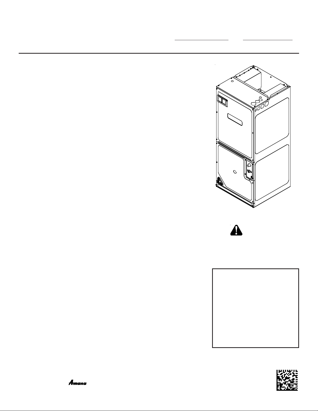
AVPTC**14**
®
AIR HANDLERS
INSTALLATION & OPERATING INSTRUCTIONS
1 Important Safety Instructions ....................................................................2
2 Shipping Inspection ..................................................................................2
2.1 Parts ..............................................................................................3
2.2 Handling ........................................................................................3
3 Codes & Regulations................................................................................3
4 Replacement Parts ...................................................................................3
5 Pre-Installation Considerations................................................................3
5.1 Preparation....................................................................................3
5.2 System Matches............................................................................3
5.3 Interconnecting Tubing..................................................................3
5.4 Clearances ....................................................................................3
5.5 Horizontal Applications ..................................................................4
6 Installation Location.................................................................................4
6.1 Upflow Installation .........................................................................4
6.2 Horizontal Left Installation .............................................................4
6.3 Downflow/Horizontal Right Installation ..........................................4
7 Refrigerant Lines ......................................................................................7
7.1 Tubing Size....................................................................................7
7.2 Tubing Preparation........................................................................7
7.3 Tubing Connections for TXV Models.............................................7
8 Condensate Drain Lines ...........................................................................7
9 Ductwork...................................................................................................8
9.1 Return Ductwork ...........................................................................8
10 Return Air Filters .....................................................................................8
11 Electric Heat ...........................................................................................9
12 Electrical and Control Wiring ................................................................10
12.1 Building Electrical Service Inspection .......................................10
12.2 Wire Sizing ................................................................................10
12.3 Maximum Overcurrent Protection (MOP) ..................................10
12.4 Electrical Connections – Supply Voltage...................................10
12.4.1 Air Handler Only (Non-Heat Kit Models) ................................ 11
12.4.2 Air Handler - Non-Circuit Breaker Heat Kits ...........................11
12.4.3 Air Handler With Circuit Breaker Heat Kit...............................11
12.5 Low Voltage Connections..........................................................11
13 Achieving 2% Low Leakage Rate.........................................................11
14 Start-Up Procedure...............................................................................11
15 Regular Maintenance ........................................................................... 11
Circulator Blower..........................................................................................14
Troubleshooting ...........................................................................................18
ComfortNet™ System ..................................................................................19
Start-Up Procedure ......................................................................................21
Regular Maintenance ...................................................................................21
Troubleshooting ...........................................................................................24
Diagnostic Codes .........................................................................................28
Wiring Diagrams ..........................................................................................29
© 2013-2014 Goodman Manufacturing Company, L.P.
5151 San Felipe, Suite 500, Houston, TX 77056
www .goodmanmfg.com - or - www.amana-hac.com
P/N: IO-443D Date: August 2014
RECOGNIZE
THIS SYMBOL AS A
SAFETY PRECAUTION.
ATTENTION
INSTALLING
PERSONNEL
Prior to installation, thoroughly familiarize yourself with this Installation
Manual. Observe all safety warnings.
During installation or repair, caution is
to be observed. It is your responsibility
to install the product safely and to educate the customer on its safe use.
is a registed trademark of Maytag Corporation or its related companies and is used under license to
Goodman Company, L.P., Houston, TX, USA. All rights reserved.
Page 2
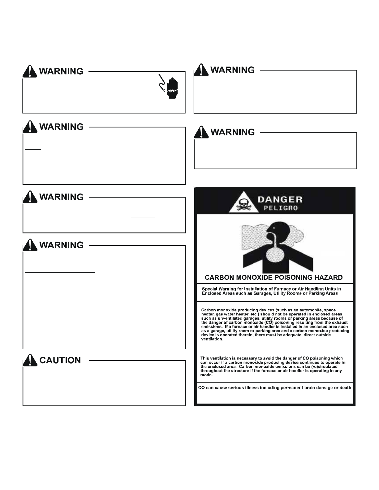
1 Important Safety Instructions
The following symbols and labels are used throughout this manual to indicate immediate or potential safety hazards. It is the
owner’s and installer’s responsibility to read and comply with all safety information and instructions accompanying these
symbols. Failure to heed safety information increases the risk of personal injury, property damage, and/or product damage.
HIGH VOLTAGE!
Disconnect ALL power before servicing.
Multiple power sources may be present.
Failure to do so may cause property damage,
personal injury or death.
Install ati on an d re pa ir of t hi s u nit sho ul d b e p erform ed
by indiv id uals me et in g the re qui re men ts of an
ONLY
“entry level technician” as specified by
the Ai r-Co ndi ti on in g, H eati ng a nd Re fri g era ti on Inst i tu te
(AHRI). Attempting to install or repair this unit without
such ba ck grou nd may re sul t i n p rod uct da mag e,
personal inju ry or death.
This product is factory-shipped for use with
208/240/1/60 electrical power supply.
reconfigure this air handler to operate with any other
power supply.
To avoid property damage, personal injury or death
due to electrical shock, this unit MUST have an
uninterrupted, unbroken
electrical ground circuit may consist of an
appropriately sized electrical wire connecting the
ground lug in the unit control box to the building
electrical service panel.
Other meth ods of gro unding are permitted if pe rfo rmed
in accordance with the National Electric Code
(NEC)/A mer ican National Stan dard s Inst itut e
(ANSI)/ Nati onal Fire P rotec tion Assoc iation (NFP A) 70
and local /s ta te c ode s. I n Canad a, e lect ri ca l gro unding
is to be in accordance with t he Cana di an El ec tr ic C ode
(CSA) C22.1.
, at a mini mum,
DO NOT
electrical ground. The
Do not connect to or use any device that is not designcertified by Goodman for use with this unit. Serious
property damage, personal injury, reduced unit
performance and/or hazardous conditions may result
from the use of such non-approved devices.
T o prev en t th e ri sk of pro perty damage, personal
injury , or dea th, do not store co mb ustible mater ials or
use gasoline or other flammable liquids or vapo rs in
the vicin ity of this uni t.
When installing or servicing this equipment, safety
clothing, including hand and eye protection, is
strongly recommended. If installing in an area that has
special safety requirements (hard hats, etc.), bserve
these requirements.
o
B10259-216
2 Shipping Inspection
Always transport the unit upright; laying the unit on its side or top during transit may cause equipment damage. The installer
should inspect the product upon receipt for shipping damage and subsequent investigation is the responsibility of the carrier.
The installer must verify the model number, specifications, electrical characteristics, and accessories are correct prior to
installation. The distributor or manufacturer will not accept claims from dealers for transportation damage or installation of
incorrectly shipped units.
2
Page 3

2.1 Parts
Also inspect the unit to verify all required components are present and intact. Report any missing components immediately to Goodman® or to the distributor. Use only factory authorized replacement parts (see Section 5). Make sure to
include the full product model number and serial number when reporting and/or obtaining service parts.
2.2 Handling
Use caution when transporting/carrying the unit. Do not move unit using shipping straps. Do not carry unit with hooks or
sharp objects. The preferred method of carrying the unit after arrival at the job site is to carry via a two-wheel hand truck
from the back or sides or via hand by carrying at the cabinet corners.
3 Codes & Regulations
This product is designed and manufactured to comply with applicable national codes. Installation in accordance with such
codes and/or prevailing local codes/regulations is the responsibility of the installer. The manufacturer assumes no responsibility for equipment installed in violation of any codes or regulations.
The United States Environmental Protection Agency (EPA) has issued various regulations regarding the introduction and disposal of refrigerants. Failure to follow these regulations may harm the environment and can lead to the
imposition of substantial fines. Should you have any questions please contact the local office of the EPA and/or refer to
EPA’s website www.epa.gov.
4 Replacement Parts
When reporting shortages or damages, or ordering repair parts, give the complete product model and serial numbers as
stamped on the product. Replacement parts for this product are available through your contractor or local distributor. For the
location of your nearest distributor consult the white business pages, the yellow page section of the local telephone book or
contact:
CONSUMER AFFAIRS
GOODMAN MANUFACTURING COMPANY, L.P.
7401 SECURITY WAY
HOUSTON, TEXAS 77040
(877) 254-4729
5 Pre-Installation Considerations
5.1 Preparation
Keep this document with the unit. Carefully read all instructions for the installation prior to installing product. Make sure
each step or procedure is understood and any special considerations are taken into account before starting installation.
Assemble all tools, hardware and supplies needed to complete the installation. Some items may need to be purchased
locally. Make sure everything needed to install the product is on hand before starting.
5.2 System Matches
The entire system (combination of indoor and outdoor sections) must be manufacturer approved and Air-Conditioning,
Heating, and Refrigeration Institute (AHRI) listed. NOTE: Installation of unmatched systems is not permitted and will void
the product warranty.
5.3 Interconnecting Tubing
Give special consideration to minimize the length of refrigerant tubing when installing air handlers. Refer to Remote
Cooling/Heat Pump Service Manual RS6200006, and TP-107 Long Line Set Application R-410A for tubing guidelines. If
possible, allow adequate length of tubing such that the coil may be removed (for inspection or cleaning services) from the
cabinet without disconnecting the tubing.
5.4 Clearances
The unit clearance from a combustible surface may be 0". However, service clearance must take precedence. A minimum of 24" in front of the unit for service clearance is required. Additional clearance on one side or top will be required
for electrical wiring connections. Consult all appropriate regulatory codes prior to determining final clearances. When
installing this unit in an area that may become wet (such as crawl spaces), elevate the unit with a sturdy, non-porous
material. In installations that may lead to physical damage (i.e. a garage) it is advised to install a protective barrier to
prevent such damage. Always install units such that a positive slope in condensate line (1/4" per foot) is allowed.
3
Page 4
5.5 Horizontal Applications
If installed above a finished living space, a secondary drain pan (as required by many building codes), must be installed
under the entire unit and its condensate drain line must be routed to a location such that the user will see the condensate
discharge.
6 Installation Location
NOTE: These air handlers are designed for indoor installation only.
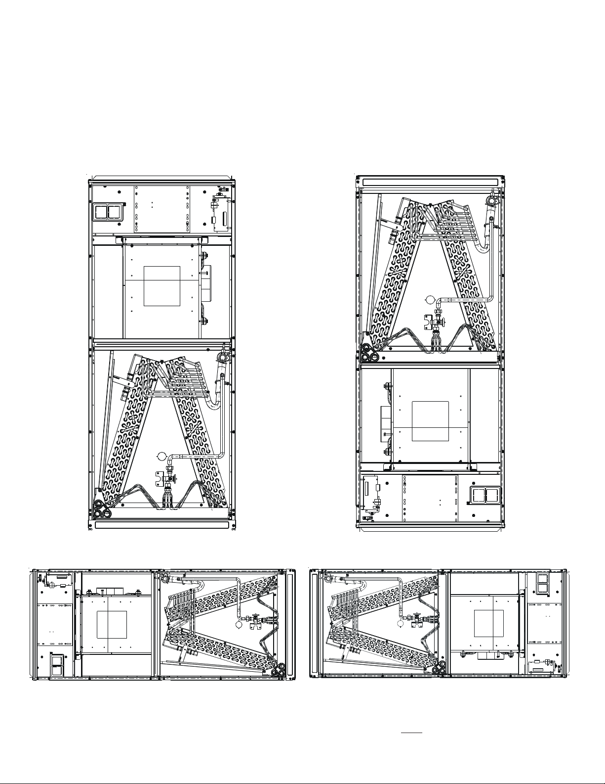
The AVPTC**14** product line may be installed in one of the upflow, downflow, horizontal left or horizontal right orientations as
shown in Figures 2, 3, 4 and 5. The unit may be installed in upflow or horizontal left orientation as shipped (refer to specific
sections for more information).
Minor field modifications are necessary to convert to downflow or horizontal right as indicated in below sections.
6.1 Upflow Installation
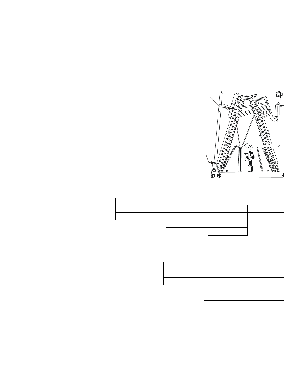
No field modifications are mandatory however to obtain maximum efficiency,
the horizontal drip shield must be removed.
Drip Shield Removal: Refer to Figure 1, remove the two (2) screws that
secure the drip shield support brackets to the condensate collectors (one
screw per side). Remove the two (2) screws that secure the drip shield to the
drain pan. The drip shield and drip shield brackets may now be removed.
The bottom left drain connection is the primary drain for this application and
condensate drain line must be attached to this drain connection. The top
connection of the three drain connections on the drain pan must remain
plugged for this application. The bottom right drain connection is for the secondary drain line (if used).
6.2 Horizontal Left Installation
No field modifications are permissible for this application.
The bottom right drain connection is the
primary drain for this application and
condensate drain line must be attached
to this drain connection. The top connection of the three drain connections
on the drain pan must remain plugged
CMK0001 CMK0002 CMK0003 CMK0007
AVPTC42D14** AVPTC48D14** AVPTC30C14** AVPTC24B14**
MODEL LISTS FOR HORIZONTAL LEFT KITS
AVPTC60D14** AVPTC36C14**
for this application. The bottom left drain
connection is for the secondary drain
line (if used).
Screw
Screw
DRIP SHIELD REMOVAL
Figure 1
AVPTC48C14**
Table 1
Use condensate management kit if equipment is installed in
high humidity condition (for example: 70% or higher).
6.3 Downflow/Horizontal Right Installation
IMPORTANT NOTE: In the downflow application, to prevent
coil pan “sweating”, a downflow kit (DFK) is available through
your local Goodman distributor. The DFK is not supplied with
the air handler and is required by Goodman on all downflow
installations. See Table 2 for the correct DFK and follow the
instructions provided for installation.
Refer to Figure 6 and 7 for the location of the components
MODEL LIST FOR DOWNFLOW KITS
DFK-B
Downflo w Kit
AVPTC24B14** AVPTC30C14** AVPTC42D14**
DFK-C
Downf l o w Ki t
AVPTC36C14** AVPTC48D14**
AVPTC48C14** AVPTC60D14**
DFK-D
Downflo w Kit
DOWNFLOW KIT
Table 2
referenced in the following steps.
1. Before inverting the air handler, remove blower access panel and coil access panel. The coil access panel and tubing
panel may remain screwed together during this procedure. Remove and retain the seven (7) screws securing the coil
access panel to the cabinet and the six (6) screws securing the blower access panel to the cabinet.
2. Slide the coil assembly out using the drain pan to pull the assembly from the cabinet.
NOTE: DO NOT USE MANIFOLDS OR FLOWRATOR TO PULL THE COIL ASSEMBLY OUT. FAILURE TO DO SO
MAY RESULT IN BRAZE JOINT DAMAGE AND LEAKS.
4
Page 5
3. Removal of the center support is required on units with 21" wide cabinet. Remove and retain the two (2) screws that
secure the center support to the cabinet. Remove the center support.
4. Using the drain pan to hold the coil assembly, slide the coil assembly back into the cabinet on the downflow brackets as
shown in Figure 8.
5. Re-install the center support (if removed) using the two (2) screws removed in Step 4.
6. Re-install the access panels removed in Step 1 as shown in Figure 9.
7. The bottom left drain connection is the primary drain for this application and condensate drain line must be attached to
this drain connection. The top connection of the three drain connections on the drain pan must remain plugged for this
application. The bottom left drain connection is for the secondary drain line (if used).
UPFLOW
Figure 2
HORIZONTAL LEFT
Figure 4
DOWNFLOW
Figure 3
HORIZONTAL RIGHT
Figure 5
NOTE: If removing only the coil access panel from the unit, the filter access panel must be removed first. Failure to do so
may result in panel damage.
5
Page 6
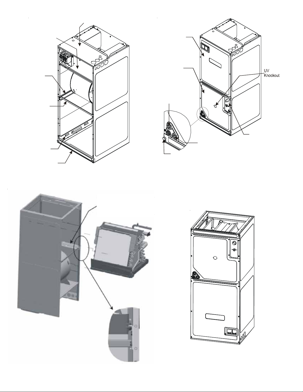
Upper Tie Plate
Control
Deck
Downflow
Bracket
Center
Support
Filter
Bracket
Filter Acces s
Panel
INTERNAL PART TERMINOLOGY
Figure 6
Blower
Access
Panel
Coil
Access
Panel
Secondary
Drain Port
for Horizontal
Application
Thumb
Screw
Secondary Dra in Port
for Upflow/Downflow
Application
EXTERNAL PART TERMINOLOGY
Figure 7
Tubing
Panel
IMPORTANT NOTE:
Ensure coil slides o n the rails
along the groove provided
on the drain pan side walls.
Failure to do so will resu lt
in improper condensate drainage.
COIL INSTALLATION FOR DOWNFLOW
Figure 8
Coil Slides
on the
downflow bracket
ACCESS PANEL
CONFIGURATION FOR
DOWNFLOW OR
HORIZONTAL RIGHT
Figure 9
6
Page 7
7 Refrigerant Lines
NOTE: Refrigerant tubing must be routed to allow adequate
access for servicing and maintenance of the unit.
Do not install the air handler in a location that violates the
instructions provided with the condenser. If the unit is located
in an unconditioned area with high ambient temperature and/
or high humidity, the air handler may be subject to nuisance
sweating of the casing. On these installations, a wrap of 2"
fiberglass insulation with a vapor barrier is recommended.
7.1 Tubing Size
For the correct tubing size, follow the specification for
the condenser/heat pump.
7.2 Tubing Preparation
All cut ends are to be round, burr free, and clean. Failure to follow this practice increases the chances for refrigerant
leaks. The suction line is spun closed and requires tubing cutters to remove the closed end.
NOTE: To prevent possible damage to the tubing joints,
do not handle coil assembly with manifold or flowrator
tubes. Always use clean gloves when handling coil assemblies.
NOTE: The use of a heat shield is strongly recommended
when brazing to avoid burning the serial plate or the finish of the unit.
sensitive components such as service valves and TXV valves sensing bulb.
This product is factory-shipped with R410A and dry
nitrogen mixture gas under pressure. Use appropriate
service tools and follow these instructions to prevent
injury .
A quenching cloth is strongly recommended to prevent
scorching or marring of the equipment finish when
brazin g close to the painted surfaces. Use brazing
alloy of 5% minimum silver content.
CAUTION
Applying too muc h heat to any tube can melt the tube. T orc h
heat required to braze tubes of various sizes must be
proportiona l to th e size of th e tube. S er vice p er sonn el m u st
use the appropriate he at level for the size of the tube being
brazed.
Heat trap or wet rags must be used to protect heat
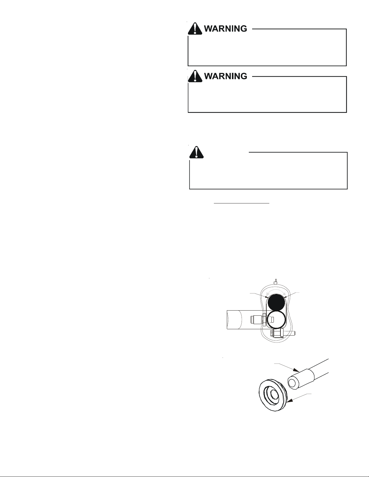
7.3 Tubing Connections for TXV Models
TXV models come with factory installed TXV with the bulb pre-installed on the vapor tube.
1. Remove refrigerant tubing panel or coil (lower) access panel.
2. Remove access valve fitting cap and depress the valve stem in access fitting to release pressure. No pressure indicates possible leak.
3. Replace the refrigerant tubing panel.
4. Remove the spin closure on both the liquid and suction tubes
using a tubing cutter.
REFRIGERANT BULB
MUST BE POSITIONED
BETWEEN 10 & 2 O’CLOCK
REFRIGERANT BULB
MUST BE POSITIONED
BETWEEN 10 & 2 O’CLOCK
5. Insert liquid line set into liquid tube expansion and slide grommet about 18" away from braze joint.
6. Insert suction line set into suction tube expansion and slide insulation and grommet about 18" away from braze joint.
7. Braze joints. Quench all brazed joints with water or a wet rag
upon completion of brazing.
NOTE: The sensing bulb must be permanently located. A heat shield,
heat trap, or wet rag must be used during brazing to prevent damage to
SUCTION LINE
WITH SPIN CLOSURE
Figure 10
the TXV valve.
8. Replace access panels, suction line grommet, insulation and all
screws.
RUBBER
GROMMET
8 Condensate Drain Lines
The coil drain pan has a primary and a secondary drain with 3/4" NPT
female connections. The connectors required are 3/4" NPT male, either
Suction Line Grommet
Figure 11
PVC or metal pipe, and should be hand tightened to a torque of no more than 37 in-lbs. to prevent damage to the drain pan
connection. An insertion depth of approximately 3/8” to 1/2” (3-5 turns) should be expected at this torque.
7
Page 8
1. Ensure drain pan hole is not obstructed.
2. To prevent potential sweating and dripping on to finished space, it may be necessary to insulate the condensate drain
line located inside the building. Use Armaflex® or similar material.
A secondary condensate drain connection has been provided for areas where the building codes require it. Pitch all drain
lines a minimum of 1/4" per foot to provide free drainage. Provide required support to the drain line to prevent bowing. If the
secondary drain line is required, run the line separately from the primary drain and end it where condensate discharge can
be easily seen.
NOTE: Water coming from secondary line means the coil primary drain is plugged and needs immediate attention.
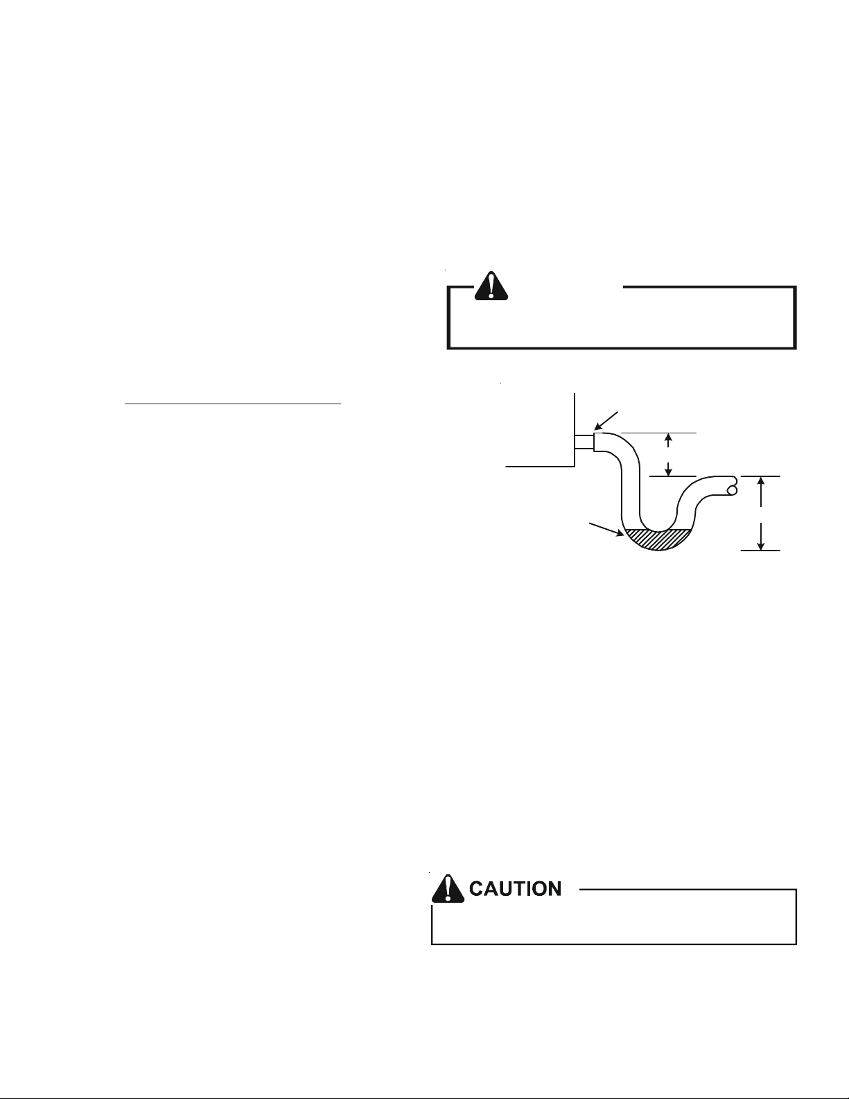
Insulate drain lines located inside the building or above a finished living space to prevent sweating. Install a condensate trap
to ensure proper drainage.
NOTE: When units are installed above ceilings, or in other locations where damage from condensate overflow may occur,
it is MANDATORY to install a field fabricated auxiliary drain pan
under the coil cabinet enclosure.
The installation must include a “P” style trap that is located as
close as is practical to the evaporator coil. See Figure 12 for
If secondary drain is not installed, the secondary
access must be plugged.
CAUTION
details of a typical condensate line “P” trap.
NOTE: Trapped lines are required by many local codes. In the
absence of any prevailing local codes, please refer to the requirements
listed in the Uniform Mechanical Building Code.
Drain
Connection
A drain trap in a draw-through application prevents air from being drawn
back through the drain line during fan operation thus preventing condensate from draining, and if connected to a sewer line to prevent sewer
Air Handler
2" MIN.
gases from being drawn into the airstream during blower operation.
Field experience has shown condensate drain traps with an open verti-
cal Tee between the air handler and the condensate drain trap can improve condensate drainage in some applications, but may cause exces-
POSITIVE LIQUID
SEAL REQUIRED
AT TRAP
3" MIN.
sive air discharge out of the open Tee. Goodman® does not prohibit this
type of drain but we also do not recommend it due to the resulting air
leakage. Regardless of the condensate drain design used, it is the
Figure 12
installer’s responsibility to ensure the condensate drain system is of sufficient design to ensure proper condensate removal from the coil drain pan.
Use of a condensate removal pump is permitted when necessary. This condensate pump should have provisions for shutting off the control voltage should a blocked drain occur. A trap must be installed between the unit and the condensate pump.
IMPORTANT NOTE: The evaporator coil is fabricated with oils that may dissolve styrofoam and certain types of plastics.
Therefore, a removal pump or float switch must not contain any of these materials.
Tip: Priming the “P” trap may avoid improper draining at the initial installation and at the beginning of the cooling season.
9 Ductwork
This air handler is designed for a complete supply and return ductwork system.
To ensure correct system performance, the ductwork is to be sized to accommodate 350-450 CFM per ton of cooling with
the static pressure not to exceed 0.5" in w.c. Refer to ACCA Manual D, Manual S and Manual RS for information on duct
sizing and application. Flame retardant ductwork is to be used and sealed to the unit in a manner that will prevent leakage.
NOTE: A downflow application with electric heat must have an L-shaped sheet metal supply duct without any outlets or
registers located directly below the heater.
9.1 Return Ductwork
DO NOT LOCATE THE RETURN DUCTWORK IN AN
AREA THAT CAN INTRODUCE TOXIC, OR OBJECTIONABLE FUMES/ODORS INTO THE DUCTWORK.
The return ductwork is to be connected to the air han-
Do not operate this product without all the ductwork
attached.
dler bottom (upflow configuration).
10 Return Air Filters
Each installation must include a return air filter. This filtering may be performed at the air handler using the factory filter rails
or externally such as a return air filter grille. When using the factory filter rails, a nominal 16x20x1”, 20x20x1” or 24x20x1”
(actual dimension must be less than 23-½”x20”) filter can be installed on a B, C and D cabinet respectively (the cabinet size
is the seventh letter of the model number).
8
Page 9
11 Electric Heat
Refer to the installation manual provided with the electric heat kit for the correct installation procedure. All electric heat must
be field installed. If installing this option, the ONLY heat kits that are permitted to be used are the HKS series. Refer to the
air handler unit’s Serial and Rating plate or the HKS specification sheets to determine the heat kits compatible with a given
air handler. No other accessory heat kit besides the HKS series may be installed in these air handlers.
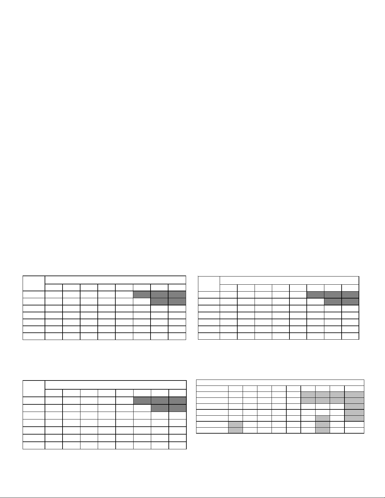
The heating mode temperature rise is dependent upon the system airflow, the supply voltage, and the heat kit size (kW)
selected. Use data provided in Tables 3, 4 and 5 to determine the temperature rise (°F).
NOTE: For installations not indicated above the following formula is to be used:
TR = (kW x 3412) x (Voltage Correction) / (1.08 x CFM)
Where: TR = Temperature Rise
kW = Heater Kit Actual kW
3412 = Btu per kW
VC* = .96 (230 Supply Volts)
= .92 (220 Supply Volts)
= .87 (208 Supply Volts)
1.08 = Constant
CFM = Measured Airflow
VC* (Voltage Correction)
NOTE: The Temperature Rise Tables can also be used to estimate the air handler airflow delivery. When using these tables
for this purpose set the room thermostat to maximum heat and allow the system to reach steady state conditions. Insert two
thermometers, one in the return air and one in the supply air. The temperature rise is the supply air temperature minus the
return air temperature. Using the temperature rise calculated, CFM can be estimated from the TR formula above. See
Technical Manual and/or Service Manual for more information.
CFM
8001219233137
1000 9 1519253044
1200 8 12152125374962
1400 7 11131821324253
1600 6 9 12 15 19 28 37 46
1800 5 8 10 14 16 25 33 41
2000 5 7 9 12 15 22 30 37
3 5 6 8 10 15 19/20 25
HEAT KIT NOMINAL kW
230/1/60 SUPPLY VOLTAGE - TEMP. RISE °F
Table 3
CF M
3 5 6 8 10 15 19/20 25
8001017212833
10008 1317222740
12007 11141922334556
14006 10121619293848
1600 5 8 10 14 17 25 33 42
18005 7 9 1215223037
20004 7 8 1113202733
HEAT KIT NOMINAL kW
208/1/60 SUPPLY VOLTAGE - TEMP. RISE °F
Table 5
CFM
8001118223035
1000 9 14 18 24 28 42
1200 7 12 15 20 24 35 47 5 9
1400 6 10 13 17 20 30 40 5 1
1600 6 9 11 15 18 27 35 44
1800 5 8 10 13 16 24 31 39
2000 4 7 9 12 14 21 28 35
3 5 6 8 10 15 19/20 25
HEAT KIT NOMINAL kW
220/1/60 SUPPLY VOLTAGE - TEMP. RISE °F
Table 4
Heater Kit (Kw)
AVPTC24B14
AVPTC30B14
AVPTC36C14
AVPTC48C14
AVPTC42D14
AVPTC48D14
AVPTC60D14
Please refer to page 16 for specific heater kit application guidelines.
3 5 6 8 1 0 15 19 20 21 or 25
550 650 700 800 850 NR NR NR NR
600 700 750 875 950 NR NR NR NR
NR 850 900 1000 1200 1440 1500 1500 NR
NR 850 900 1000 1200 1440 1500 1500 NR
†
850** 1250 1300 1500 1550 1720 NR 1800 NR
††
NR 1250 1300 1500 1550 1720 NR 1815 1850
†††
NR 1250 1300 1500 1550 1780 NR 1850 1850
MINIMUM CFM REQUIRED FOR HEATER KITS
Table 6
9
Page 10
12 Electrical and Control Wiring
IMPORTANT: All routing of electrical wiring must be made through provided electrical knockouts. Do not cut, puncture or
alter the cabinet for electrical wiring.
12.1 Building Electrical Service Inspection
This unit is designed for single-phase electrical
supply only. DO NOT OPERATE ON A THREEPHASE POWER SUPPLY. Measure the power
supply to the unit. The supply voltage must be
measured and be in agreement with the unit
nameplate power requirements and within the
range shown.
12.2 Wire Sizing
Wire size is important to the operation of your equipment. Use the following check list when selecting the
appropriate wire size for your unit.
• Wire used must carry the Minimum Circuit Ampac-
ity (MCA) listed on the unit’s Series and Rating
Plate.
Nominal Input Minimum Voltage Maximum Voltage
208-240 197 253
ELECTRICAL VOLTAGE
Table 7
FIRE HAZARD!
To avoid the risk of property damage, personal injury
or fire, use only copper conductors.
• Refer to the NEC (USA) or CSA (Canada) for wire sizing. The unit MCA for the air handler and the optional
electric heat kit can be found on the unit Series and
Rating Plate.
• Wire must be sized to allow no more than a 2%
voltage drop from the building breaker/fuse panel
to the unit.
• Wires with different insulation temperature rating have
varying ampacities - be sure to check the temperature
rating used.
Refer to the latest edition of the National Electric Code
or in Canada the Canadian Electric Code when determining the correct wire size.
12.3 Maximum Overcurrent Protection (MOP)
Every installation must include an NEC (USA) or CEC
(Canada) approved overcurrent protection device.
Also, check with local or state codes for any special
regional requirements.
Protection can be in the form of fusing or HACR style
circuit breakers. The Series and Rating Plate provides
the maximum overcurrent device permissible.
NOTE: Fuses or circuit breakers are to be sized larger than the
equipment MCA but not to exceed the MOP.
HIGH VOLTAGE!
Disconnect ALL power before servicing.
Multiple power sources may be present.
Failure to do so may cause property damage,
personal injury or death.
HIGH VOLTAGE!
T o avoid prope rty dama ge , persona l injury or death
due to el ect rical shock, this unit MUST have an
uninterrupted, unbroken
electrical ground circuit may consist of an
appro pri at ely sized electrical wire connecting the
ground lug in the unit control box to the building
electrica l s ervice panel.
Other methods of grounding are p ermitted if pe rformed
in ac co rda n ce w ith th e N a tio na l E le ctr ic C ode
(NEC) /Americ an Nation al Standar ds Institu te
(ANSI)/National Fire Protection Assoc iation (NFPA ) 70
and local/state codes. In Canada, electrical gro unding
is to be in ac co rda nce w ith t he Cana dian E lectric C ode
(CSA) C22.1.
electrical ground. The
Top of
Cabinet
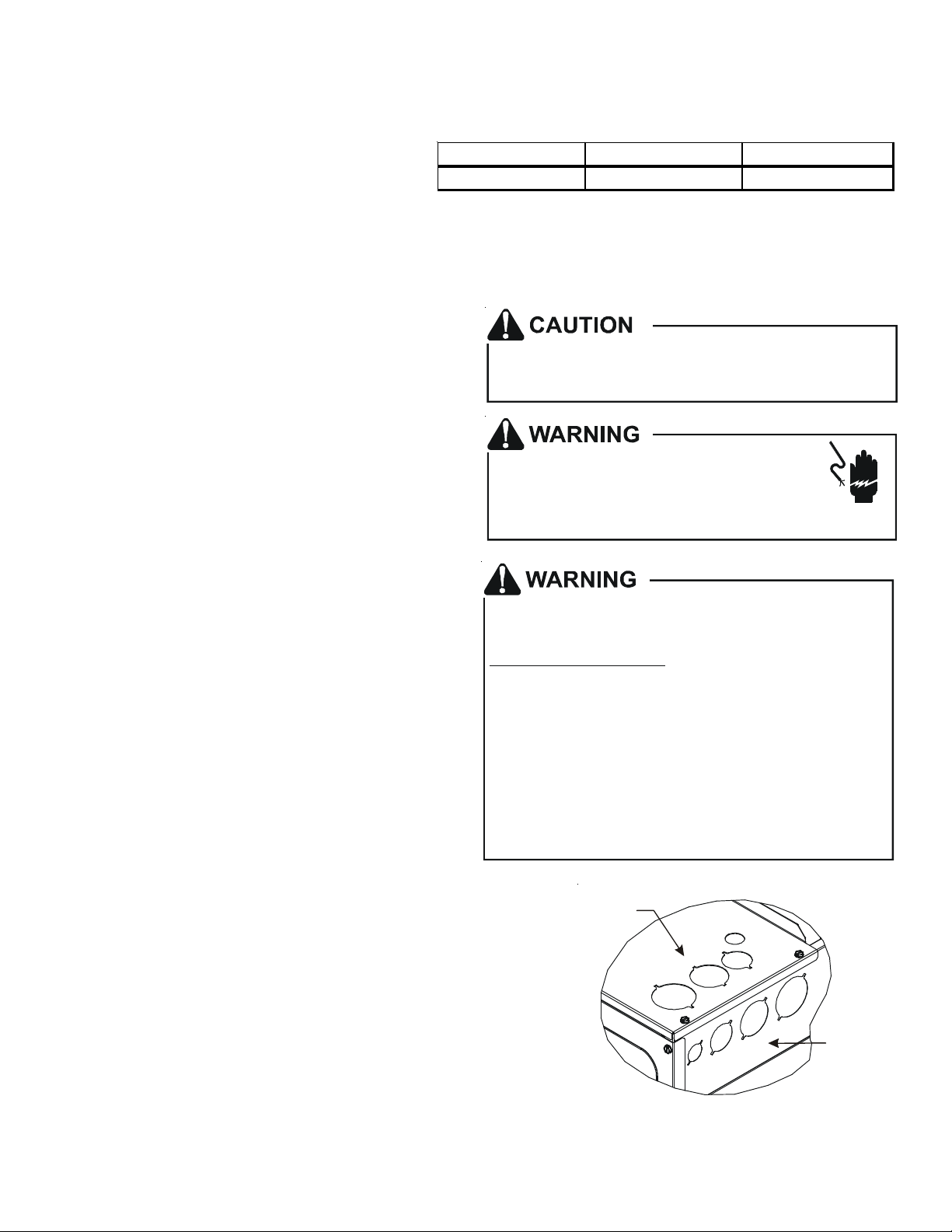
12.4 Electrical Connections – Supply Voltage
IMPORTANT NOTE: USE COPPER CONDUCTORS ONLY.
Knockouts are provided on the air handler top panel and sides of
the cabinet to allow for the entry of the supply voltage conductors,
as shown in Figure 13. If the knockouts on the cabinet sides are
used for electrical conduit, an adapter ring must be used in order
to meet UL1995 safety requirements. An NEC or CEC approved
strain relief is to be used at this entry point. Some codes/municipalities require the supply wire to be enclosed in conduit. Consult
your local codes.
Side of
Cabinet
KNOCK-OUT FOR ELECTRICAL
CONNECTIONS
Figure 13
10
Page 11

12.4.1 Air Handler Only (Non-Heat Kit Models)
The building supply connects to the stripped black and red wires contained in the air handler electrical compartment
cavity. A ground screw is also contained in this area. Attach the Supply wires to the air handler conductors as shown
in the unit wiring diagram using appropriately sized solderless connectors or other NEC or CEC approved means.
12.4.2 Air Handler - Non-Circuit Breaker Heat Kits
A terminal block is provided with the HKS kit to attach the power supply and air handler connections. Follow the HKS
Installation Manual and wiring diagram for complete wiring details.
12.4.3 Air Handler With Circuit Breaker Heat Kit
The air handler has a plastic cover on the upper access panel that will require either one or both sections to be
removed to allow the heat kit circuit breaker(s) to be installed. The circuit breakers have lugs for power supply
connection. See the HKS Installation Instructions for further details.
12.5 Low Voltage Connections
Several combinations of low voltage schemes are possible, depending on the presence of a heat kit and whether the
heat kit is single-stage or multi-stage, whether the outdoor section is an air conditioner or heat pump, and whether the
system is setup with a communicating or traditional thermostat. The 24V-control voltage connects the air handler to
the room thermostat and condenser. Low voltage wiring must be copper conductors. A minimum of 18AWG must be
used for installations up to 50’ and 16AWG for installations over 50’. Low voltage wiring must be connected through
the top of the cabinet or either side. See the “Thermostat Wiring” section of this manual for typical low voltage wiring
connections.
13 Achieving 2% Low Leakage Rate
Ensure all the gaskets remain intact on all surfaces as shipped with the unit. These surfaces are areas between the upper tie
plate and coil access panel, blower access and coil access panels, and between the coil access and filter access panels.
Ensure upon installation, that the plastic breaker cover is sitting flush on the blower access panel and all access panels are
flush with each other and the cabinet. With these requirements satisfied, the unit achieves less than 2% airflow leakage
when tested in accordance with ASHRAE Standard 193.
14 Start-Up Procedure
• Prior to start-up, ensure that all electrical wires are properly sized and all connections are properly tightened.
• All panels must be in place and secured. For Air Tight application, gasket must be positioned at prescribed locations
to achieve 2% leakage.
• Tubing must be leak free.
• Condensate line must be trapped and pitched to allow for drainage.
• Low voltage wiring is properly connected.
• Auxiliary drain is installed when necessary and pitched to allow for drainage.
• Unit is protected from vehicular or other physical damage.
• Return air is not obtained from, nor are there any return air duct joints that are unsealed in, areas where there may be
objectionable odors, flammable vapors or products of combustion such as carbon monoxide (CO), which may cause
serious personal injury or death.
15 Regular Maintenance
The only item required to be maintained on a regular basis
by the user is the circulating air filter(s). Filter should be
cleaned or replaced regularly, typically once per month. A
certified service technician must perform all other services.
IMPORTANT NOTE: If thumb screws are used to access the
filter, ensure the washer installed on the screw behind the
access panel remains in place after re-installation.
HIGH VOLTAGE!
Disconnect ALL power before servicing or
installing this unit. Multiple power sources may
be present. Failure to do so may cause property
damage, personal injury or death.
11
Page 12

24 VOLT THERMOSTAT WIRING - NON-COMMUNICATING THERMO-
A
A
STAT CONNECTIONS
NOTE: Wire routing must not interfere with the circulator
blower operation or routine maintenance.
The air handler’s integrated control module provides terminals for
“Y1” and “Y2” and “W1” and “W2” thermostat connections. This
allows the air handler to support the systems shown in the following table. Refer to the following figures for typical connections to
the integrated control module. Thermostat wiring entrance holes
are located in the top of the blower. Wire routing must not interfere
COOLING HEAT PUMP HEATING E LECTRIC HEATING
1-STAGE ----- - 1- or 2-STAGE
2-STAGE ----- - 1- or 2-STAGE
1-STAGE 1-STAGE -----2-STAGE 2-STAGE -----1-S T AGE 1-S TA GE 1- or 2- S T AG E
2-S T AGE 2-S TA GE 1- or 2- S T AG E
Table 8
with circulator blower operation or routine maintenance.
NOTE: A removable plug connector is provided with the control to make thermostat wire connections. This plug may
be removed, wire connections made to the plug, and replaced. It is
STRONGLY recommended that you do not connect
multiple wires into a single terminal. Wire nuts are recommended to ensure one wire is used for each terminal. Failure to do
so may result in intermittent operation.
Typical Single-Stage Cool,
Single-Stage Heat Thermostat
RCG
12RCG
RC
Remote Con densing Unit
(Single -Sta ge AC)
W1 Y1
W1 Y1 Y2
W2
Y
Place Jumper Between Y1
and O for Proper
Dehumidification Operation
and Proper Ramping
Profile Operation
Air Handler Integrated
DEHUM
O
NEU
HOT
Control Module
Dehumidistat
[Optional]
Typical Single-Stage Cooling with Single-Stage Heating
Figure 14
RCG
12RC
W/E
W1 W2 Y1 Y2
G
Y1
Typical Single-Stage Cool,
O
O
Single-Stage Heat
Heat Pump Thermostat
DEHUM
Integrated Control Module
ir Handler
Typical Two-Stage Cool,
Two-Stage Heat Thermostat
RCG
12RCG
RC
Remote Con densing Unit
W1 W2 Y1 Y2
W1 W2 Y1 Y2
Y1 Y2
(T wo-S tage A C)
Place Jumper Between Y1
and O for Proper
Dehumidification Operation
and Proper Ramping
Profile Operation
Air Handler Integrated
DEHUM
O
NEU
HOT
Control Module
Dehumidistat
[Optional]
Typical Two-Stage Cooling with Two-Stage Heating
Figure 15
RCG
12RC
W/E
W2 Y1 Y2
W1 W2 Y1 Y2
G
Typical Two-Stage Cool,
O
O
Two-Stage Heat
Heat Pump Thermostat
DEHUM
Integrated Control Module
ir Handler
RC
W1 Y
Remote Condensing Unit
(Single-Stage HP)
Typical Single-Stage Heat Pump
with Auxiliary/Emergency Heating
Figure 16
O
NEU
HOT
Dehumidistat
[Optional]
RC
W1 Y1 Y2
Remote Condensing Unit
(T wo -S ta ge HP)
O
NEU
HOT
Dehumidistat
[Optional]
Typical Two Stage Heat Pump Heating
and Auxiliary/Emergency Heating
Figure 17
24 VOLT DEHUMIDISTAT WIRING - NON-COMMUNICATING THERMOSTAT CONNECTIONS
The optional usage of a dehumidistat allows the air handler’s circulator blower to operate at a slightly lower speed during a
combined thermostat call for cooling and dehumidistat call for dehumidification. This lower blower speed enhances dehumidification of the conditioned air as it passes through the AC coil. For proper function, a dehumidistat applied to this air
handler must operate on 24 VAC and utilize a switch which opens on humidity rise.
To install/connect a dehumidistat:
12
Page 13

1. Turn OFF power to air handler.
A
A
2. Secure the dehumidistat neutral wire (typically the white lead) to the screw terminal marked “DEHUM” on the air
handler’s integrated control module.
3. Secure the dehumidistat hot wire (typically the black lead) to the screw terminal marked “R” on the air handler’s
integrated control module.
4. Secure the dehumidistat ground wire (typically the green lead) to the ground
screw on the air handler. NOTE: Ground wire may not be present on all
dehumidistats.
5. To enable the dehumidification function, move the dehumidification dip switch
(S7) from OFF to ON. See following figure.
6. Turn ON power to air handler.
S5 S6 S7 S8
ON
OFF
Dip Switches -
Dehumidification Enable
Figure 18
Move to the
ON position
to enable
dehumidification
AUXILIARY ALARM SWITCH
The control is equipped with two Auxiliary Alarm terminals labeled CAS which can
be utilized with communicating mode setups (typically used for condensate switch
wiring but could be used with compatible C02 sensors or fire alarms).
Legacy mode use
In a legacy system (Non-communicating), this feature is not operational. Any aux-
CAS
iliary alarm switch must be used to interrupt the Y1 signal either to the indoor or
outdoor unit.
Communication mode use
This feature can be activated or deactivated through the thermostat user menus.
An auxiliary alarm switch must be normally closed and open when the base pan’s
water level in the evaporator coil reaches a particular level. The control will respond by turning off the outdoor compressor and display the proper fault codes. If the switch is detected closed for 30 seconds, normal operation resumes and the
error message will be removed.
Figure 19
SWITCH
AVPTC MOTOR ORIENTATION
If the unit is in the upflow position, there is no need to rotate
the motor. If the unit is in the downflow position, loosen motor
mount and rotate motor as shown in the AVPTC Motor Orien-
tation figure below. Be sure motor is oriented with the female
connections on the casing down. If the motor is not oriented
with the connections down, water could collect in the motor
and may cause premature failure.
FRONT VIEW
FEMALE CONNECTIONS
AVPTC Motor Otrientation
Figure 20
SIDE VIEW
W
RNING
SOFTW
RE VER.
TOP
13
Page 14

Seven Segment
LED
Green CFM LED
2
W1W2
C
ST1
3
ST4
24VAC
TH
TR
COM
FUSE
3A
ST3
CAS
DE
HUM
Y2
Y1
W2
W1
G
C
R
2
ST2
Auxiliary
Alarms
O
1
C
2
1
R
Dip Switches
Communicating Board
Figure 21
C
IRCULATOR BLOWER
This air handler is equipped with a multi-speed circulator blower. This blower provides ease in adjusting blower speeds.
The Specification Sheet applicable to your model provides an airflow table, showing the relationship between airflow (CFM)
and external static pressure (E.S.P.), for the proper selection of heating and cooling speeds. The heating blower speed
shipped is set at 21kW or 25kW, and the cooling blower speed is set at “D”. These blower speeds should be adjusted by the
installer to match the installation requirements so as to provide the correct electric heating CFM and correct cooling CFM.
Use the CFM LED (green) to obtain an approximate airflow quantity. The green CFM LED blinks once for each 100 CFM of
airflow.
1. Determine the tonnage of the cooling system installed with the air handler. If the cooling capacity is in BTU/hr divide it
by 12,000 to convert capacity to TONs.
Example: Cooling Capacity of 30,000 BTU/hr.
30,000/12,000 = 2.5 Tons
2. Determine the proper airflow for the cooling system. Most cooling systems are designed to work with airflows between
350 and 450 CFM per ton. Most manufacturers recommend an airflow of about 400 CFM per ton.
Example: 2.5 tons X 400 CFM per ton = 1000 CFM
The cooling system manufacturer’s instructions must be checked for required airflow. Any electronic air cleaners or other
devices may require a specific airflow; consult installation instructions of those devices for requirements.
3. Knowing the air handler model, locate the high stage cooling airflow charts in the Specification Sheet applicable to your
model. Look up the cooling airflow determined in step 2 and find the required cooling speed and adjustment setting.
Example: An AVPTC30C14 air handler installed with a 2.5 ton air conditioning system. The airflow needed is 1000
CFM. Looking at the cooling speed chart for AVPTC30C14, find the airflow closest to 1000 CFM. A cooling airflow of
1000 CFM can be attained by setting the cooling speed to “C” and the adjustment to “0” (no adjustment).
14
Page 15

4. Locate the blower speed selection DIP switches on the integrated control module. Select the desired “cooling” speed tap by positioning
switches 1 and 2 appropriately. If airflow adjustment is required, set
dip switch S8 (trim enable) to ON (trim enable default is off). Then
select the desired “adjust” tap by positioning switches S3 and S4 appropriately. Refer to the following Airflow Adjust Taps figure for switch
positions and their corresponding taps. Verify CFM by counting the
number of times the green CFM LED blinks, see page 13 for LED
locations.
Tap A Tap B
OFF OFF OFF OFFON ON ON ON
S1
S2
Cooling Airflow Speed Tap (*indicates factory setting)
S1
S2
Tap C Tap D *
S1
S2
S1
S2
5. Continuous fan speeds that provide 25, 50, 75, and 100% of the air
handler’s maximum airflow capability are selectable via dip switches
S12 and S13.
If the air handler’s maximum airflow capability is 2000 CFM and 25%
continuous fan speed is selected, the continuous fan speed will be 0.25
x 2000 CFM = 500 CFM.
6. The multi-speed circulator blower also offers several custom ON/OFF
ramping profiles. These profiles may be used to enhance cooling
performance and increase comfort level. The ramping profiles are
selected using DIP switches 5 and 6. Refer to the following Dip
Switches - Cooling Airflow Ramping Profiles figure for switch positions and their corresponding taps. Refer to the bullet points below
for a description of each ramping profile. Verify profile selection by
counting the green CFM LED blinks and timing each step of the ramping profile.
+5% -5%
OFF OFF OFF OFFON ON ON ON
S3
S4
S3
S4
Airflow Adjust Taps (*indicates facto r y se tting)
+10% -10%
S3
S4
Dip Switches -
Cooling Airflow and Airflow Adjust Taps
25% 50%*
OFF
OFF
S12
S13
12
13
S12
S13
Fan Only Selection (*indicates factory setting)
Fan Only Selection (*indicates factory setting)
ON
ON
OFF
OFF
12
13
75% 100%
OFF
OFF
ON ON
ON ON
S12
12
S13 S13
13
S3
S4
OFFON
OFFON
12
13
21 kW* or
25 kW*
OFF OFF OFF OFFON ON ON ON
S9
S10
S11
19 kW or
20 kW
S9
S10
S11
15 kW 10 kW
S9
S10
S11
S9
S10
S11
8 kW 6 kW 5 kW 3 kW
OFF OFF OFF OFFON ON ON ON
S9
S10
S11
S9
S10
S11
S9
S10
S11
S9
S10
S11
Electric Heating Airflow (*indicates factory setting)
NOTE: Upon start up in communicating mode the circuit board may display an “Ec” error. This is an indication that the dip
switches on the control board need to be configured in accordance with the Electric Heating Airflow Table. Configuring
the dip switches and resetting power to the unit will clear the error code.
Within the thermostat user menu, CTK0* communicating thermostat will display 20 kW for OFF-OFF-ON dip switch
selection and 21 kW for OFF-OFF-OFF dip switch selection.
15
Page 16

• Profile A provides only an OFF delay of one (1)
minute at 100% of the cooling demand airflow.
OFF
100% CFM 100% CFM
OFF
1 min
• Profile B ramps up to full cooling demand airflow by
first stepping up to 50% of the full demand for 30
seconds. The motor then ramps to 100% of the
OFF
50% CFM
1/2 min
required airflow. A one (1) minute OFF delay at
100% of the cooling airflow.
• Profile C ramps up to 82% of the full cooling demand
airflow and operates there for approximately 7 1/2
OFF
minutes. The motor then steps up to the full demand
airflow. Profile C also has a one (1) minute 100%
OFF delay.
• Profile D ramps up to 50% of the demand for 1/2
minute, then ramps to 82% of the full cooling de-
OFF
mand airflow and operates there for approximately
7 1/2 minutes. The motor then steps up to the full
demand airflow. Profile D has a 1/2 minute at 50%
airflow OFF delay.
7. If an electric heater kit has been installed, determine the heater kilowatt (kW) rating. Using the Electric Heat Airflow table on page 16,
set dip switches 9, 10, and 11 for the installed heater. The adjust
setting (already established by the cooling speed selection) also applies to the electric heater kit airflow. Thus, the electric heater airflow
is adjusted by the same amount. This does not apply to systems
setup with a communicating thermostat. See Set-Up section in the
AIR HANDLER ADVANCED FEATURES MENU on page 22. Verify selected
CFM by counting the green CFM LED blinks.
If an electric heater kit has not been installed, set dip switches 9, 10,
and 11 to any valid heater kit setting (see ariflow table for valid settings). This will prevent an Ec Error code from being displayed.
100% CFM
100% CFM
Tap A* Tap B Tap C Tap D
OFF OFF OFF OFFON ON ON ON
S5
S6
Dip Switches - Coolkng Airflow Ramping Profiles
S5
S6
S5
S6
100% CFM
1 min
OFF
S5
S6
OFF
OFF
NOTE: For installations not indicated in the preceding Temperature Rise Tables, the following formula is to be used:
TR = (kW x 3412) x (Voltage Correction) / (1.08 x CFM)
Where: TR = Temperature Rise
kW = Heater Kit Actual kW
3412 = Btu per kW
Voltage Correction =.96 (230 Supply Volts)
=.92 (220 Supply Volts)
=.87 (208 Supply Volts)
1.08 = Constant
CFM = Measured Airflow
NOTE: The Temperature Rise Tables can also be used to determine the air handler airflow delivery. When using these
tables for this purpose set the room thermostat to maximum heat and allow the system to reach steady state conditions.
Insert two thermometers, one in the return air and one in the supply air. The temperature rise is the supply air temperature
minus the room air temperature.
Use HKR specification sheets to determine the HKR available for a given air handler.
16
Page 17

RNR
RNR
RNR
RNR
RNRNR
RNR
RNRNRNRNR
Speed Selection Dip Switches
Cooling/Heat Pump Airflow Table
Cool Adjust Profile
Selection Selection Selec t ion
Switches Switches Switches
TAP S1 S2 S3 S4 S5 S6
A OFF OFF OFF OFF OFF OFF
B ON OFF ON OFF ON OFF
C OFF ON OFF ON OFF ON
D ON ON ON ON ON ON
Profiles Pre-Run Short-Run OFF Delay
A ------- -------- 60 sec/100%
B ------- 30 sec /5 0% 60 s ec/100%
C ------- 7.5 min/82% 60 sec/100%
D 30 sec /50% 7.5 min/82% 30 sec/50%
To set Airflow:
Airflow. Determine the corresponding tap (A, B, C, D). Set dip
switches S1 and S2 to the appropriate ON / OFF positions.
(2) Select model and installed electric heater size. Set dip
switches S9, S10, and S11 to the appropriate ON / OFF positions.
(3) If airflow adjustment is required set Trim Enable Switch to
ON (OFF = 0% Trim) and set S3 and S4 to appropriate ON / OFF
positions. Tap A is +5%,Tap B is -5%, Tap C is +10%, Tap D is
-10%.
To Set Comfort mode:
profiles above). Set dip switches S5 and S6 to appropriate ON /
OFF positions.
Dehumidification:
airflow will be reduced to 85% of nominal value during cool call
when Dehum command is present. To disable, set S7 to OFF.
Continuous Fan Speed:
one of 4 continuous fan speeds, Tap A is 25%. Tap B is 50%, Tap
C is 75%, Tap D is 100%.
Notes:
1. Airflow data shown applies to legacy mode operation only.
For a fully communicating system, please see the outdoor
unit's install ation instructions for cooling and heat pump
ai r f low data. See
section for details.
2. Airflow blink codes ar e approximations of actual airflow.
(1) Select model and desired High Stage Cooling
Select desired Comfort Mode Profile (see
To enable, set dip switch S7 to ON. Cooling
Use dip switches S12 and S13 to s elect
ComfortNet System-Airflow Consideration
Continuous
Fan
Speed
S12
OFF
ON
OFF
ON
S13
OFF
OFF
ON
ON
S8
Model Spe ed tap
A
AVPTC24B14**
B
C
D
A
AVPTC30C14**
B
C
D
A
AVPTC36C14**
B
C
D
A
AVPTC48C14**
B
C
D
A
AVPTC42D14**
B
C
D
A
AVPTC48D14**
B
C
D
A
AVPTC60D14**
B
C
D
NOTE: Airflow blink codes are approximations of actual airflow. Airflows provided
are at 0.3 static.
Low stage
(CFM)
410 610
565 835
660 970
765 1125
440 610
605 835
740 1020
885 1225
500 725
700 1000
930 1330
1120 1600
500 725
700 1000
930 1330
1120 1600
560 800
763 1090
994 1420
1225 1750
900 1350
1035 1550
1140 1700
1200 1800
1210 1610
1365 1815
1450 1920
1525 2025
High stage
(CFM)
EL E C TRIC HEAT AIRFLOW TAB LE
H TR kW 9 10 11 AVPTC24B14A AVPTC30C14A AVPTC36C14A AVPTC48C14A AVPTC42D14A† AVPTC48D14A†† AVPTC60D14A†††
3 ON ON ON 550 600 N
5 ON ON OFF 650 700 850 850 1250 1250 1250
6 ON OFF ON 700 750 900 900 1300 1300 1300
8 ON OFF OFF 800 875 1000 1000 1500 1500 1500
10 OFF ON ON 850 950 1200 1200 1550 1550 1550
15 OFF ON OFF N
19* N
OFF OFF ON
20 N
21 or 25* OFF OF F OFF N
Note: Airflow data shown applies to the electric heat only in either legacy mode or communicating mode operationNR - Not rated* Within thermostat
user menu, CTK0* communicating thermostat will display 20 kW for OFF-OFF-ON dip switch selection and 21 kW for OFF-OFF-OFF dip switch
selection.
† For match up with a 2 ton outdoor unit: Heater kit application shall not exceed 10 kW. Airflow for 5 kW up to 10 kW heater kits shall be set to 850 cfm speed t ap of
ON-ON-ON.
†† For match up with a 3 ton outdoor unit: Heater kit application shall not exceed 15 kW.
Airflow for 5 kW up to 15 kW heater kits shall be set to 1300 cfm speed tap of ON-OFF-ON.
††† For match up with a 3.5 ton outdoor unit: Heater kit application shall not exceed 20 kW.
Airflow for 5 kW up to 20 kW heater kits shall be set to 1500 cfm speed tap of ON-OFF-OFF
** 3 kW heater kit is not applicable for this indoor application.
1440 1440 1720 1720 1780
1500 1500 N
1500 1500 1800 1815 1850
850** N
1850 1850
17
Page 18

HEAT KIT SELECTION
For heat kit selection, see the Specification Sheet for each specific Air Handler.
T
ROUBLESHOOTING
ELECTROSTATIC DISCHARGE (ESD) PRECAUTIONS
NOTE: Discharge body’s static electricity before touching unit. An electrostatic discharge can adversely affect electrical
components.
Use the following precautions during air handler installation and servicing to protect the integrated control module from
damage. By putting the air handler, the control, and the person at the same electrostatic potential, these steps will help
avoid exposing the integrated control module to electrostatic discharge. This procedure is applicable to both installed and
uninstalled (ungrounded) blowers.
1. Disconnect all power to the blower. Do not touch the integrated control module or any wire connected to the control
prior to discharging your body’s electrostatic charge to ground.
2. Firmly touch a clean, unpainted, metal surface of the air handler blower near the control. Any tools held in a person’s
hand during grounding will be discharged.
3. Service integrated control module or connecting wiring following the discharge process in step 2. Use caution not to
recharge your body with static electricity; (i.e., do not move or shuffle your feet, do not touch ungrounded objects, etc.).
If you come in contact with an ungrounded object, repeat step 2 before touching control or wires.
4. Discharge your body to ground before removing a new control from its container. Follow steps 1 through 3 if installing
the control on a blower. Return any old or new controls
to their containers before touching any ungrounded object.
DIAGNOSTIC CHART
Refer to the Troubleshooting Chart at the end of this manual
for assistance in determining the source of unit operational
problems. The 7 segment LED display will provide any active
fault codes. An arrow printed next to the display indicates
proper orientation (arrow points to top of display). See Figure
21.
HIGH VOLTAGE!
TO
AVOID PERSONAL INJURY OR DEATH DUE TO
ELECTRICAL SHOCK, DISCONNECT ELECTRICAL POWER
BEFORE PERFORMING ANY SERVICE OR MAINTENANCE
WARNING
.
7 Segment
Diagnostic
Display
Figure 22
18
Page 19

FAULT RECALL
The integrated control module is equipped with a momentary push-button switch that can be used to display the last six
faults on the 7 segment LED display. The control must be in Standby Mode (no thermostat inputs) to use the feature.
Depress the push-button for approximately two seconds and less than five seconds. The LED display will then display the
six most recent faults beginning with the most recent fault and decrementing to the least recent fault. The faults may be
cleared by depressing the button for greater than five seconds.
NOTE: Consecutively repeated faults are displayed a maximum of three times. Example: A clogged return air filter causes
the air handler’s motor to repeatedly enter a limiting condition. The control will only store this fault the first three consecutive
times the fault occurs.
C
OMFORTNET
™ S
YSTEM
OVERVIEW
The ComfortNet system is a system that includes a ComfortNet compatible air handler and air conditioner or heat pump with
a CTK0* thermostat. Any other system configurations are considered invalid ComfortNet systems and must be connected
as a traditional (or non-communicating) system (see the 24 VOLT THERMOSTAT WIRING - NON-COMMUNICATING THERMOSTAT CON-
NECTIONS section for details).
A ComfortNet heating/air conditioning system differs from a non-communicating/traditional system in the manner in which
the indoor unit, outdoor unit and thermostat interact with one another. In a traditional system, the thermostat sends commands to the indoor and outdoor units via analog 24 VAC signals. It is a one-way communication path in that the indoor and
outdoor units typically do not return information to the thermostat.
On the other hand, the indoor unit, outdoor unit, and thermostat comprising a ComfortNet system “communicate” digitally
with one another. It is now a two-way communications path. The thermostat still sends commands to the indoor and outdoor
units. However, the thermostat may also request and receive information from both the indoor and outdoor units. This
information may be displayed on the ComfortNet thermostat. The indoor and outdoor units also interact with one another.
The outdoor unit may send commands to or request information from the indoor unit. This two-way digital communications
between the thermostat and subsystems (indoor/outdoor unit) and between subsystems is the key to unlocking the benefits
and features of the ComfortNet system.
Two-way digital communications is accomplished using only two wires. The thermostat and subsystem controls are powered with 24 VAC Thus, a maximum of 4 wires between the equipment and thermostat is all that is required to operate the
system.
AIRFLOW CONSIDERATION
Airflow demands are managed differently in a fully communicating system than they are in a non-communicating wired
system. The system operating mode (as determined by the thermostat) determines which unit calculates the system
airflow demand. If the indoor unit is responsible for determining the airflow demand, it calculates the demand and sends it
to the ECM motor. If the outdoor unit or thermostat is responsible for determining the demand, it calculates the demand
and transmits the demand along with a fan request to the indoor unit. The indoor unit then sends the demand to the ECM
motor. The table below lists the various ComfortNet systems,
the operating mode, and airflow demand source.
For example, assume the system is a heat pump matched with
an air handler. With a call for low stage cooling, the heat pump
will calculate the system’s low stage cooling airflow demand. The
heat pump will then send a fan request along with the low stage
cooling airflow demand to the air handler. Once received, the air
handler will send the low stage cooling airflow demand to the
ECM motor. The ECM motor then delivers the low stage cooling
airflow. See the applicable ComfortNet air conditioner or heat
pump installation manual for the airflow delivered during cooling
or heat pump heating.
System
Air Conditioner +
Air Handl er
Heat Pu mp + Air
Handler
System
Operating Mode
Cooling A ir Conditioner
Heating Air Handler
Continuous Fan Thermostat
Cooling Heat Pu mp
Heat Pump Heating
Only
HP + Electric Heat
Strips
Electric Heat Strips
Only
Airflow Demand
Source
Heat Pu mp
> of Heat Pum p or Air
Handler Demand
Air Handler
19
Continuous Fan Thermostat
Page 20

In continuous fan mode, the CTK0* thermostat provides the airflow demand. Depending on which CTK0* thermostat has been
A
A
g
installed three or four continuous fan speeds may be available. If the thermostat provides three speeds (low, medium, high)
they correspond to 25%, 50% and 75%, respectively, of the air handlers’ maximum airflow capability. If the thermostat
provides four continuous fan speeds then a 100% airflow option is added. During continuous fan operation, the thermostat
sends a fan request along with the continuous fan demand to the air handler. The air handler, in turn, sends the demand to
the ECM motor. The ECM motor delivers the requested continuous fan airflow.
CTK0* THERMOSTAT WIRING
NOTE: Refer to section Electrical Connections for 208/230 volt line connections to the air handler.
NOTE: A removable plug connector is provided with the control to make thermostat wire connections. This plug may be
removed, wire connections made to the plug, and replaced. It is
multiple wires into a single terminal. Wire nuts are recommended to ensure one wire is used for each terminal.
Failure to do so may result in intermittent operation.
Typical 18 AWG thermostat wire may be used to wire the system components. One hundred (100) feet is the maximum
length of wire between indoor unit and outdoor unit, or between indoor unit and thermostat.
FOUR-WIRE INDOOR AND OUTDOOR WIRING
Typical wiring will consist of four wires between the indoor unit and outdoor
unit and between the indoor unit and thermostat. The required wires are: (a)
data lines, 1 and 2; (b) thermostat “R” (24 VAC hot) and “C” (24 VAC common).
STRONGLY recommended that you do not connect
CTK0*
RC
12
12RC
Thermostat
CT™ Compatible
ir Handler Blower
Integrated Control Module
12RC
System Wiring Using Four-Wires
CT™ Compatible AC/HP
Integrated Control Module
Figure 23
TWO-WIRE OUTDOOR, FOUR-WIRE INDOOR WIRING
Two wires only may be utilized between the indoor and outdoor units. For this wiring scheme, only the data lines, 1 and 2,
are required between the indoor and outdoor units. A 40VA,
208/230 VAC to 24 VAC transformer must be installed in the
outdoor unit to provide 24 VAC power to the outdoor unit’s electronic control. See kit instructions for mounting and wiring instructions. Four wires are required between the indoor unit
and thermostat.
12RC
12RC
40VA Transformer
208/230 VAC
System Wiring using Two-Wires between Air Handler and AC/
HP and Four-Wires between Air Handler and Thermostat
24 VAC
Figure 24
12
RC
CTK0*
Thermostat
CT™ Compatible
ir Handler Blower
rated Control
Inte
Module
CT™ Compatible
AC/HP Integrated
Control Module
COMFORTNET™ SYSTEM ADVANCED FEATURES
The ComfortNet system permits access to additional system information, advanced set-up features, and advanced diagnostic/troubleshooting features. These advanced features are organized into a menu structure. See the AIR HANDLER ADVANCED FEATURES MENU section for layout of menu shortcuts.
DIAGNOSTICS
Accessing the air handler’s diagnostics menu provides ready access to the last six faults detected by the air handler. Faults
are stored most recent to least recent. Any consecutively repeated fault is stored a maximum of three times. Example: A
clogged return air filter causes the air handler’s motor to repeatedly enter a limiting condition. The control will only store this
fault the first three consecutive times the fault occurs.
NOTE: It is highly recommended that the fault history be cleared after performing maintenance or servicing the air handler.
20
Page 21

NETWORK TROUBLESHOOTING
The ComfortNet system is a fully communicating system, and thus, constitutes a network. Occasionally the need to troubleshoot the network may arise. The integrated air handler control has some on-board tools that may be used to troubleshoot
the network. These tools are: red communications LED, green receive (Rx) LED, and learn button. Refer to the Communi-
cations Troubleshooting Chart at the end of this manual for error codes, possible causes and corrective actions
• Red communications LED – Indicates the status of the network. The table below indicates the LED status and the
corresponding potential problem.
• Green receive LED – Indicates network traffic. The table below indicates the LED status and the corresponding
potential problem.
• Learn button – Used to reset the network. Depress the button for approximately 2 seconds to reset the network.
SYSTEM TROUBLESHOOTING
NOTE: Refer to the instructions accompanying the ComfortNet compatible outdoor AC/HP unit for troubleshooting information.
Refer to the Troubleshooting Chart at the end of this manual for a listing of possible air handler error codes, possible causes
and corrective actions.
S
TART-UP PROCEDURE
• Prior to start-up, ensure that all electrical connections are properly sized and tightened.
• All panels must be in place and secured. For Air Tight application, neoprene gasket must be positioned at prescribed
locations to achieve 2% leakage.
• Tubing must be leak free.
• Unit should be elevated, trapped and pitched to allow for drainage.
• Low voltage wiring is connected.
• Auxiliary drain is installed when necessary and pitched to allow for drainage.
• Drain pan and drain tubing has been leak checked.
• Return and supply ducts are sealed.
• Unit is elevated when installed in a garage or where flammable vapors may be present.
• Unit is protected from vehicular or other physical damage.
• Return air is not obtained from any areas where there may be objectionable odors, flammable vapors or products of
combustion such as carbon monoxide (CO), which may cause serious personal injury or death.
R
EGULAR MAINTENANCE
The only item to be maintained on a regular basis by the user
is the circulating air filter(s). Filter should be cleaned or replaced regularly. A certified service technician must perform
all other services.
NOTE: THESE INSTRUCTIONS ARE SPECIFICALLY FOR
AVPTC MODELS. DO NOT USE THESE DIAGRAMS FOR
ANY OTHER MODELS. SEE SEPARATE INSTALLATION
AND OPERATING INSTRUCTIONS FOR ATUF, ARUF,
ARPT, ADPF, AND ASPF MODELS.
HIGH VOLTAGE!
Disconnect ALL power before servicing or
installing this unit. Multiple power sources may
be present. Failure to do so may cause property
damage, personal injury or death.
NOTICE: THIS PRODUCT CONTAINS ELECTRONIC COMPONENTS WHICH REQUIRE A DEFINITE GROUND.
PROVISIONS ARE MADE FOR CONNECTION OF THE GROUND. A DEDICATED GROUND FROM THE MAIN
POWER SUPPLY OR AN EARTH GROUND MUST BE PROVIDED.
21
Page 22

COMMUNICATIONS TROUBLESHOOTING CHART
LED LED
Status
1 Flash
Red
Communications
LED
2 Flashes
1 Steady
Green Receive
LED
Rapid
Flashing
On Solid
Off
Off
Flash
Indication Possible Causes Corrective Action(s) Notes & Cautions
• Normal condition • None • None • None
• Communications
Failure
• Out-of-box reset • Contr ol power up
• No power
• Communications
error
• No network found • Broken/ disconnected
• Normal network
traffic
• Data 1/ Data 2
miss-wire
• Communications
Failure
• Learn bu tton
depressed
• No power to air
handler
• Open fuse
• Communications error
data wire(s)
• Air hand ler is instal le d
as a legacy/ traditional
system
• Control is “talking” on
network as expec ted
• Data 1 and data 2
wires reversed at air
handler, thermostat,
or CT™ c o m patible
outdoor AC/HP
• Short between data 1
and data 2 wires
• Short between data 1
or data 2 wires and R
(24VAC) or C (24VAC
common)
• Depress Lear n Button
• Verify that bus BIAS
and TERM
dipswitches are in the
ON position.
• None • None
• Check fuses and
circuit breaker s;
replace/reset
• Replac e blown fuse
• Check for shorts in
low voltage wiring in
air handler/system
• Reset n etwork by
depressing learn
button
• Check data 1/ data 2
voltages
• Check
communications
wiring (data 1/ data 2
wires)
• Check wire
connections at
terminal block
• Verify a ir handler
installation type
(legac y/ traditional or
communicating)
• Check data 1/ data 2
voltages
• None • None
• Check
communications
wiring (data 1/ data 2
wires)
• Check wire
connections at
terminal block
• Check data 1/ data 2
voltages
• Depress once
quic k ly f or a powerup reset
• Dep ress and hold
for 2 seconds for
an out-of -box reset
• Turn power OFF
prior to repair
• Turn power OFF
prior to repair
• Verify wires at
terminal blocks are
securely t wiste d
together prior to
insert ing into
terminal block
• Veri fy data 1 and
data vo ltages as
described above
• Turn power OFF
prior to repair
• Verify wires at
terminal blocks are
securely t wiste d
together prior to
insert ing into
terminal block
• Veri fy data 1 and
data vo ltages as
described above
22
Page 23

AIR HANDLER ADVANCED FEATURES MENU
CONFIGURATION
Submenu Item
Electric Heat Size (HTR KW)
Motor HP (1/2, 3/ 4, or 1 MTR HP)
Heat ON Delay (HT ON) Display s the electric heat indoor bl ower ON delay .
Heat OFF Delay (HT OFF) Dis plays the electric heat indoor bl ower OFF del ay.
Submenu Item Indication/User Modifiable Options Comments
Fault 1 (FAU LT #1) Mos t rec ent modular fault For dis play only
Fault 2 (FAU LT #2) Next m os t recent modul ar fault For dis play only
Fault 3 (FAU LT #3) Next m os t recent modul ar fault For dis play only
Fault 4 (FAU LT #4) Next m os t recent modul ar fault For dis play only
Fault 5 (FAU LT #5) Next m os t recent modul ar fault For dis play only
Fault 6 (FAU LT #6) Least rec ent modular fault For dis play only
Clear Fault His tory (CLEA R) NO or YES Selecting “Y E S” clears the fault hi s tory
Consecutively repeated fault s are shown a maxim um of 3 ti m es
NOTE:
Displ ay s the s ize in kW of t he s el ec ted elec t ri c heaters.
Displ ay s the ai r handler i ndoor blower mot or horsepower.
Indication (for Display Only; not User Modifia ble)
DIAGNOSTICS
IDENTIFICATI ON
Submenu Item
Model Number (MOD NUM) Displays the modular blower model num ber
Serial Number (SER NUM) Dis pl ays the modular blower s erial num ber (Opti onal )
Software (SOFTW A RE ) Displ ay s the applicat i on s oft ware revision
Submenu Item Use r Modifiable Options Comments
Heat Ai rflow Trim (HT TRM) -10% to + 10% i n 2% increm ents, default i s 0%
Submenu Item
Mode (MODE) Displ ay s the c urrent air handler operati ng m ode
CFM (CFM) Displ ay s the ai rflow for the c urrent operati ng m ode
Indication (for Display Only; not User Modifia ble)
SET-UP
STATUS
Indication (for Display Only; not User Modifia ble)
Trims t he heat ing ai rflow
by t he s el ected amount.
23
Page 24

TROUBLESHOOTING
Notes & Cautions
Corrective Actions
Possible Causes
x Normal operation x None x Normal operation
x Turn power OFF prior to
x Verify electric heat dipswitch
x Heater kit selected via
EC
repair.
x Use memory card for
settings
x Verify the installed electric
dipswitches is too large for
heater kits in shared data set
the specific model.
heater is valid for the air
BEFORE turning power
x Insert memory card
handler blower. Check
nameplate or Specification
ON. Memory card may
Sheet applicable to your
be removed after data is
loaded.
model* for allowable heater
kit(s).
x Turn power off before
x Verify shared data set is
repair.
the specific model.
BEFORE turning power
ON. Memory card may
be removed after data is
removing memory card.
x Turn power OFF prior to
x Use memory card for
x Insert memory card
correct for the specific model.
Re-populate data using
correct memory card if
required.
settings
heater is valid for the air
dipswitches is too small for
x Verify the installed electric
heater kits in shared data set
handler blower. Check
x Verify electric heat dipswitch
x Heater kit selected via
EC
loaded.
removing memory card.
x Turn power off before
nameplate or Specification
Sheet applicable to your
model* for allowable heater
kit(s).
correct for the specific model.
Re-populate data using
x Verify shared data set is
repair.
the specific model.
BEFORE turning power
ON. Memory card may
be removed after data is
loaded.
removing memory card.
x Turn power OFF prior to
x Use memory card for
x Insert memory card
settings
heater is valid for the air
handler blower. Check
nameplate or Specification
Sheet applicable to your
correct memory card if
required.
x Verify electric heat dipswitch
x Verify the installed electric
dipswitches is doesn’t match
heater kits in shared data set
x Heater kit selected via
EC
model* for allowable heater
x Turn power off before
kit(s).
correct for the specific model.
Re-populate data using
x Verify shared data set is
correct memory card if
required.
service.
x Turn power OFF prior to
service
x Check overflow pan and
evaporation coil.
x High water level in the
EF
ComfortNet™
None None
Thermostat Only
Message Code
HTR TOO
Fault Description
x Heater kit selected via
x Normal operation
EC
ON
Codes
Characters
Will Alternate
7-Segment LED
LARGE
dipswitches is too
large for heater kits
specified in shared
SMALL
HTR TOO
data set
x Heater kit selected via
EC
dipswitches is too
small for heater kits
specified in shared
data set
MATCH
NO HTR
dipswitches does not
heater kits specified in
x Heater kit selected via
EC
shared data set
Fault
Aux Alarm
x Aux switch open
EF
Symptoms of Abnormal Operation
(Legacy & ComfortNet™ Thermostat)
call for W1 or Auxiliary/Emergency
x LED display is ON continuously
x Electric heaters fail to energize on a
heat
provides the indicated error code.
Service” icon illuminated
x ComfortNet™ thermostat “Call for
“Check Air Handler” message
x ComfortNet™ thermostat scrolls
x Integrated control module LED display
expected on a call for W1 or
Auxiliary/Emergency heat
x Electric heat airflow is higher than
provides the indicated error code.
x Integrated control module LED display
expected on a call for W1 or
Auxiliary/Emergency heat
x Electric heat airflow is higher than
provides the indicated error code.
x Integrated control module LED display
x Integrated control module LED display
EF error code.
x ComfortNet™ thermostat “Call for
Service”.
24
Page 25

TROUBLESHOOTING
repair.
control module fuse with
3A automotive fuse.
control module with
correct replacement part
x Turn power OFF prior to
x Replace integrated
x Replace integrated
volt power to air handler
blower and integrated control
module.
x Assure 208/230 volt and 24
Possible Causes Corrective Actions Notes & Cautions
or 24 volt wire improperly
x Manual disconnect switch OFF
EE
module fuse (3A). Replace if
x Check integrated control
connected or loose
an internal fault
x Blown fuse or circuit breaker
x Integrated control module has
“Electrostatic Discharge”
x Read precautions in
necessary.
208/230 volt and 24 volt
circuits. Repair as necessary.
x Check for possible shorts in
section of manual.
x Replace bad integrated
control module.
repair
the specific model.
x Turn power OFF prior to
x Use memory card for
using memory card.
x Populate shared data set
contain any shared data.
x Air handler blower does not
d0
repair
BEFORE turning power
ON. Memory card may
be removed after data is
loaded.
cleared once data is
loaded.
x Insert memory card
x Error code will be
x Turn power off before
removing memory card
the specific model.
x Turn power OFF prior to
x Use memory card for
set using memory card.
x Populate correct shared data
contain an appropriate shared
data set.
x Air handler blower does not
d1
BEFORE turning power
ON. Memory card may
be removed after data is
x Insert memory card
loaded.
x Error code will be
cleared once data is
loaded.
x Turn power OFF prior to
x Verify shared data set is
x Shared data set on memory
d4
repair
x Use memory card for
correct for the specific model.
Re-populate data using
card has been rejected by
integrated control module
the specific model.
BEFORE turning power
ON. Memory card may
be removed after data is
loaded.
cleared once data is
loaded.
x Insert memory card
correct memory card if
required.
x Error code will be
x Turn power off before
removing memory card
ComfortNet™
Thermostat Only
Codes
7-Segment LED
FAULT
Message Code
INTERNAL
Fault Description
to air handler blower
x No 208/230 volt power
No Display
Characters
Will Alternate
or no 24 volt power to
integrated control
module
breaker
x Blown fuse or circuit
DATA
NO NET
module has an internal
fault.
x Integrated control
x Data not yet on
d0
network.
INVALID
x Invalid data on
d1
DATA
network.
INVALID
x Invalid memory card
d4
MC DATA
data.
Symptoms of Abnormal Operation
(Legacy & ComfortNet™ Thermostat)
provides no signal.
x Air handler blower fails to operate
x Integrated control module LED display
x ComfortNet™ thermostat “Call for
Service” icon illuminated
x ComfortNet™ thermostat scrolls
“Check Air Handler” message
provides indicated error code.
Service” icon illuminated.
x Air handler blower fails to operate.
x Integrated control module LED display
“Check Air Handler” message.
x ComfortNet™ thermostat “Call for
x ComfortNet™ thermostat scrolls
provides indicated error code.
Service” icon illuminated.
x Air handler blower fails to operate.
x Integrated control module LED display
“Check Air Handler” message.
x ComfortNet™ thermostat “Call for
x ComfortNet™ thermostat scrolls
operation.
provides indicated error code.
Service” icon illuminated.
x Operation different than expected or no
x Integrated control module LED display
“Check Air Handler” message.
x ComfortNet™ thermostat “Call for
x ComfortNet™ thermostat scrolls
25
Page 26

TROUBLESHOOTING
Notes & Cautions
Corrective Actions
Possible Causes
x Turn power OFF prior to
x Tighten or correct wiring
x Loose wiring connection at
b0
repair
x Replace circulator motor
connection.
x Check circulator blower
circulator motor power leads
or circulator motor power
with correct
replacement part.
motor. Replace if necessary.
leads disconnected.
x Failed circulator blower motor.
x Turn power OFF prior to
x Tighten or correct wiring
x Loose wiring connection at
b1
repair
x Replace circulator motor
connection.
x Check circulator blower
circulator motor control leads.
x Failed circulator blower motor.
with correct
replacement part.
motor. Replace if necessary.
x Check integrated control
module.
x Failed integrated control
control module with
x Replace integrated
module. Replace if
necessary.
correct replacement
part.
x Turn power OFF prior to
x Verify circulator blower motor
x Incorrect circulator blower
b2
repair
x Replace motor with
horse power is the same
specified for the specific air
motor in air handler blower.
x Incorrect shared data set in
correct replacement
part.
x Use memory card for
handler blower model.
Replace is necessary.
x Verify shared data set is
integrated control module.
the specific model
x Insert memory card
correct for the specific model.
Re-populate data using
for installation requirements.
x See "Installation Instructions"
repair.
x Turn power OFF prior to
grills/registers, duct system,
x Check filters, filter
sudden change in speed or
x Abnormal motor loading,
b4
and air handler blower/coil air
inlet/outlet for blockages.
torque, sudden blockage of air
handler blower/coil air inlet or
outlet.
blocked filters, very restrictive
x High loading conditions,
ductwork, blockage of air
handler blower/coil air inlet or
outlet.
BEFORE turning power
ON. Memory card may
be removed after data is
loaded.
cleared once shared
data and motor horse
power match.
removing memory card
x Error code will be
correct memory card if
required.
x Turn power off before
x Turn power OFF prior to
x Check filters for blockage.
x Blocked filters.
b3
repair.
Clean filters or remove
obstruction.
x Restrictive ductwork.
x Undersized ductwork.
x Check ductwork for blockage.
x High ambient temperatures.
Remove obstruction. Verify
all registers are fully open.
x Verify ductwork is
appropriately sized for
system. Resize/replace
ductwork if necessary.
ComfortNet™
Thermostat Only
MOTOR
Message Code
NOT RUN
Fault Description
motor is not running
x Circulator blower
b0
Codes
Characters
Will Alternate
7-Segment LED
when it should be
running.
MOTOR
x Integrated control
b1
COMM
module has lost
MOTOR
MISMATCH
communications with
circulator blower
motor.
x Circulator blower
b2
motor horse power in
shared data set does
not match circulator
blower motor horse
power.
MOTOR
x Circulator blower
b3
LIMITS
motor is operating in a
power, temperature, or
speed limiting
condition.
MOTOR
x Circulator blower
b4
TRIPS
motor senses a loss
rotor control.
x Circulator blower
motor senses high
current.
Symptoms of Abnormal Operation
(Legacy & ComfortNet™ Thermostat)
provides indicated error code.
x Air handler blower fails to operate.
x Integrated control module LED display
Service” icon illuminated.
“Check Air Handler” message.
provides indicated error code.
Service” icon illuminated.
x ComfortNet™ thermostat “Call for
x ComfortNet™ thermostat scrolls
x Air handler blower fails to operate.
x Integrated control module LED display
“Check Air Handler” message.
x ComfortNet™ thermostat “Call for
x ComfortNet™ thermostat scrolls
provides indicated error code.
Service” icon illuminated.
x Air handler blower fails to operate.
x Integrated control module LED display
“Check Air Handler” message.
x ComfortNet™ thermostat “Call for
x ComfortNet™ thermostat scrolls
performance.
x Air handler blower operates at reduced
provides b3 error code.
x Airflow delivered is less than expected.
x Integrated control module LED display
provides indicated error code.
Service” icon illuminated.
x Air handler blower fails to operate.
x Integrated control module LED display
“Check Air Handler” message.
x ComfortNet™ thermostat “Call for
x ComfortNet™ thermostat scrolls
26
Page 27

TROUBLESHOOTING
Notes & Cautions
Corrective Actions
Possible Causes
repair
x Turn power OFF prior to
obstructions. Remove and
x Check circulator blower for
blower housing.
x Obstruction in circulator
b5
correct replacement
part.
x Replace motor with
repair/replace wheel/motor if
necessary.
x Check circulator blower motor
bearings.
x Seized circulator blower motor
x Failed circulator blower motor.
repair.
correct replacement
part.
x Turn power OFF prior to
x Replace wheel with
blower. Verify line voltage to
blower is within the range
specified on the air handler
blower rating plate.
hander blower.
x High ambient temperatures.
for installation requirements.
x See "Installation Instructions"
shaft rotation and motor.
Replace motor if necessary.
x Check power to air handler
handler blower.
x High AC line voltage to air
x Low AC line voltage to air
b6
repair.
x Turn power OFF prior to
module. Verify control is
x Check integrated control
module.
x Error with integrated control
b7
x Replace with correct
populated with correct shared
x Motor has a locked rotor
replacement part(s).
x Use memory card for
data set. See data errors
above for details.
condition.
the specific model.
x Check for locked rotor
BEFORE turning power
ON.
removed after data is
x Memory card may be
loaded
x Insert memory card
condition (see error code
above for details).
x Turn power off before
repair.
removing memory card.
x Turn power OFF prior to
Clean filters or remove
obstruction.
Remove obstruction. Verify
all registers are fully open.
appropriately sized for
system. Resize/replace
x Check filters for blockage.
x Blocked filters.
b9
x Restrictive ductwork.
x Check ductwork for blockage.
x Undersized ductwork.
ductwork if necessary.
x Verify ductwork is
ComfortNet™
MTR
Thermostat Only
LCKD
Message Code
Fault Description
motor fails to start 10
x Circulator blower
b5
Codes
Characters
Will Alternate
7-Segment LED
ROTOR
consecutive times.
VOLTS
MOTOR
motor shuts down for
x Circulator blower
b6
over or under voltage
condition.
x Circulator blower
motor shuts down due
to over temperature
condition on power
module.
MOTOR
x Circulator blower
b7
PARAMS
motor does not have
LOW ID
AIRFLOW
enough information to
operate properly.
Motor fails to start 40
consecutive times.
demanded.
x Airflow is lower than
b9
Symptoms of Abnormal Operation
(Legacy & ComfortNet™ Thermostat)
provides indicated error code.
x Air handler blower fails to operate.
x Integrated control module LED display
Service” icon illuminated.
“Check Air Handler” message.
x ComfortNet™ thermostat “Call for
x ComfortNet™ thermostat scrolls
provides indicated error code.
Service” icon illuminated.
x Air handler blower fails to operate.
x Integrated control module LED display
“Check Air Handler” message.
x ComfortNet™ thermostat “Call for
x ComfortNet™ thermostat scrolls
provides indicated error code.
Service” icon illuminated.
x Air handler blower fails to operate.
x Integrated control module LED display
“Check Air Handler” message.
x ComfortNet™ thermostat “Call for
x ComfortNet™ thermostat scrolls
x Air handler blower operates at reduced
performance or operates on low stage
when high stage is expected.
provides indicated error code.
x Integrated control module LED display
27
Page 28

DIAGNOSTIC CODES
7 SEGMENT LE D
(characters will
alternate)
(no di s play ) INTE RNAL CONTROL FAULT / NO POWE R
On STANDBY, WAITING FOR INPUTS
Ed HEATER KIT DIP SWITCHES NOT SET PROPERLY
Eb NO HTR KIT INSTALLED - SYSTEM CALLING FOR AUXILIARY HEAT
E5 FUSE OPEN
EF AUXILIARY SWITCH OPEN
d0 DATA NOT ON NE TW ORK
d1 INVALID DATA ON NETWORK
d4 INV ALID MEMORY CA RD DATA
b0 BLOWER MOTOR NOT RUNNING
b1 BLOW ER MOTOR COMMUNICATION ERROR
b2 BLOWER MOTOR HP MISMATCH
b3 BLOWER MOTOR OPERATING IN POWER, TEMP., OR SPEED LIMIT
b4 BLOWER MOTOR CURRENT TRIP OR LOST ROTOR
b5 BLOWER MOTOR ROTOR LOCKED
b6 OVER/UNDER VOLTAGE TRIP OR OVER TEMPERATURE TRIP
b7 INCOMPLETE PARAME TE R SENT TO MOTO R
b9 LOW INDOOR AIRFLOW
C1 LOW STAGE COOL - LEGACY MODE ONLY
C2 HIGH STAGE COOL - LEGACY MODE ONLY
P1 LOW STAGE HEAT PUMP HEAT - LEGACY MODE ONLY
P2 HIGH STAGE HEAT PUMP HEAT - LEGACY MODE ONLY
h1 EMERGENCY HEAT LOW - COMMUNICATING MODE ONLY
h2 EMERGENCY HEAT HIGH - COMMUNICATING MODE ONLY
FC FAN CO OL - COMMUNICA TING MODE ONLY
FH FAN HEAT - COMMUNICATING MODE ONLY
FFAN ONLY
H1 ELECTRIC HEAT LOW
H2 ELECTRIC HEAT HIGH
dF
DESCRIPTION OF CONDITION
DEFROST - COMMUNICATING MODE ONLY
(note: defrost is displayed as H1 in a legacy s etup)
GREEN CFM LED - EACH FLASH REPRESENTS 100CFM (USE FOR AIRFLOW
AP PROXIMATION ONLY) - EXAMPLE: 8 FLASHES = 800CFM
28
0140A00079-A
Page 29

WIRING DIAGRAMS
A
)
WARNING
HIGH VOLTAGE!
MULTIPLE POW ER SOURCES MAY BE PRESENT. FAILURE TO DO SO
DISCO NNECT ALL POWER BEFORE SERVICING.
MAY CAUSE PROPERTY DAMAGE, PERSONAL INJURY OR DEATH.
FL
FL
BK
RD
L1
L2
TL
HTR2
TL
HTR1
M3
M1
R
M2
M4
RD
BK
BK
RD
TW O (2 ) E L EM E N T ROWS
FL
HTR1
BK
TL
FL
TL
HTR2
RD
BK
BK
1
2
RD
PU
3
BL
4
5
WH
6
7
8
9
FL
YL
RD
BK
L1
L2
L1
RD
TL
HTR3
YL
RD
BK
BL
M1
M3
M1
M4
M2
M2
R1
BK
R2
RD
YL
BK
RD
L2
THR EE (3) ELEMENT ROWS
BK
1
2
PU
3
RD
BL
4
5
BR
WH
6
7
8
9
BK
L1
L2
FL
HTR1
TL
M1
R
M2
BK
BK
RD
ONE (1) ELEMENT ROWS
BK
1
BK
2
RD
PU
3
BL
4
5
WH
7
8
9
NOTE: WHEN INSTALLING HEATER KIT, ENSURE SPEED TAP DOES NOT EXCEED MINIMUM BLOWER SPEED (MBS) SPECIFIED FOR THE AIRHANDLER/HEAT
KIT COMBINATION ON THIS UNIT'S S&R PLATE. AFTER INSTALLING OPTIONAL HEAT KIT, MARK AN "X" IN THE PROVIDED ABOVE.
MARK ACCORDING TO NUMBER OF HEATER ELEMENT ROWS INSTALLED. NO MARK INDICATES NO HEAT KIT INSTALLED.
L1
TH
W1 (1)
W2 (2)
CAS (1)
CAS (2)
+VDC (1)
RX (2)
TX (3)
GND (4)
TR
COM
INTEGRATED CONTROL MODULE
RD
PL1
BK
PL2
2
3
1
6
5
4
7
8
9
SEE
NOTE 7
2
3
1
6
5
4
7
8
9
BL
GY
BK
RD
RD
BK
BK
WH
BR
BL
4
SEE NOTE 6
4
3
2
1
RD
ECM MOTOR
HARNESS
3
RD
2
1
W1
C
W2
1
SEE NOTE 5
FAULT
RECALL
STATUS
LED
CFM LED
TRIM %
AF SELECT
S1 S2 S3 S4 S5 S6 S7 S8 S9 S10 S11 S12 S13
LEARN
SEE NOTE 6
COOL AF PROFILE
DEHUM ENABLE
DIP SWITCHES
BL
7 SEGMENT
DIAGNOSTIC
DISPLAY
TRIM ENABLE
CIRCULATOR BLOWER
3
2
4
1
24 V 3 A
SEE NOTE 6
RX LED
HTR KIT(KW)
1
2
3
4
5
BK
GND
RD
TR
TH
COM
FUSE
CAS
SEE NOTE 8
DEHUM
O
Y2
Y1
W2
W1
G
CONT FAN
C
R
1
GN
RD
BL
GND
GN
24 V THERMOSTAT CONNECTIONS
DISCONNECT
R
24V THERMOSTAT CONNECTIONS
W1
W2
Y1
Y2
G
O
DEHUM
C
L1
FUSE 3 A
TO
MICRO
FL
TL
HTR1
FL
TL
HTR2
FL
TL
HTR3
FL
TL
HTR4
PU
BL
RD
BK
M5
M1
M3
YL
M4
RD
M2
M6
R1
BK
BK
RD
YL
BL
BK
RD
FOUR (4) ELEMENT ROWS
L2
L2
L1
L1
GND
INDOOR
IR
CIRCULATOR
BLWR
208/230 VAC
40 VA
TRANSFORMER
24 VAC
HEAT SEQUENCER R1
HEAT SEQUENCER R2
COND EN S ATE SW ITCH
BK
RD
YL
BL
BL
M7
M8
R2
L2
GND
BK
RD
BL
BR
WH
INDOOR
AIR
CIRCULATOR
BLWR
COLOR CODES:
PK ---- PINK
BR ---- BROWN
1
2
3
4
5
6
7
8
9
WH ---- WHITE
BL ---- BLUE
GY ---- GRAY
RD ---- RED
YL ---- YELLOW
OR ---- ORAN GE
PU ---- PURPLE
GN ---- GREEN
BK ---- BLA CK
ER
LOW VOL TAGE (24V)
LOW VOLT AGE FIELD
HI VOLTAGE (230V
HI VOLTAGE FIELD
JUNCTION
TERMINAL
INTERNAL TO
INTEGRATED CONTROL
EQUIPMENT GND
FIELD GND
FIELD SPLICE
RESISTOR
OVERCURRENT
PROT . DEVICE
PLUG CONNECTION
NOTES:
1. PLACE RED WIRES ON TRANSFORMER
TERMINAL 2 FOR 208 VAC OPERATION.
2. MANUFACTURER'S SPECIF IE D
REPLACEMENT PARTS MUST BE USED
L2
WHEN SERVICING.
3. IF ANY OF THE ORIGINAL WIRES AS
SUPPLIED WITH THIS UNIT MUST
BE REPLACED, IT MUST BE REPLACED
WITH W IRI NG MATERIAL HAVING A
TEMPERATURE RATI NG OF AT LEAST 105°C.
USE COPPER CONDUCTORS ONLY.
4. UNIT MUST BE PERMANENTLY GROUNDED
AND CONFORM TO N.E.C AND LOCAL CODES.
5. TO RECALL THE LAST 6 FAULTS, MOST
RECENT TO LEAST RECENT, DEPRESS
SWITCH FOR MORE THAN 2 SECONDS
WHILE IN ST ANDBY (NO THERMOSTAT
INPUTS)
6. RED STATUS LED PROVI DES NETWORK
STATUS. GREEN RX LED I NDICATES NETWORK
TRAFFIC. USE LEARN BUTTON TO RESET
NETWORK.
7. DISCARD CONNECTOR PL1 WHEN
INSTALLING OPTIONAL HEAT KIT.
8. THE CONDENSATE ALARM SWITCH (CAS)
TERMINALS CAN ONLY BE UTILIZED WITH
COMMUNICATING MODE SETUPS AND MUST
BE ENABLED WITH A COMMUNICATING
THERMO STAT. THIS FE ATURE IS
NOT OPERATIONAL WITH LEGACY
GND
SYSTEMS.
USE N.E.C CLASS 2 WIRE.
0140A00071-B
Wiring is subject to change. Always refer to the wiring diagram on the unit for the most up-to-date wiring.
29
Page 30

WIRING DIAGRAMS
WARNING
3-Phase Heat Kit
HIGH VOLTAGE!
MULTIPLE POW ER SOURCES MAY BE PRESENT. FAILURE TO DO SO
MAY CAUSE PROPERTY DAMAGE, PERSONAL INJURY OR DEATH.
DISCO NNECT ALL POWER BEFORE SERVICING.
Wiring is subject to change. Always refer to the wiring diagram on the unit for the most up-to-date wiring.
30
Page 31

WIRING DIAGRAMS
25kW Heat Kit
TL
TL
TL
TL
BK
RD
BL
PU
YL
WARNING
HTR1
FL
HTR2
FL
HTR3
FL
TL
HTR4
HTR5
BK
M2R1M4
M1
BK
RD
YL
BL
BK
RD
RD
BL
FL
FL
PU
M6
M3
M5
HIGH VOLTAGE!
DISCO NNECT ALL POWER BEFORE SERVICING.
MULTIPLE POW ER SOURCES MAY BE PRESENT. FAILURE TO DO SO
MAY CAUSE PROPERTY DAMAGE, PERSONAL INJURY OR DEATH.
BK
RD
YL
BL
M7
M8
R2
WH
M10
M9
BL
PU
PC
1
BK
2
WH
3
RD
BL
4
5
BR
6
7
8
9
COMPONENT CODE
PC = 9 PIN CONNECTOR
HTR = HEATER ELEMENT
TL = THERMA L LM T
R3
RS = RELAY/SEQUENCER
TB = TERMINAL BLOCK
CB = CIRCUIT BREAKER
CC = CONTACTOR
FL = FUSE LINK
EM = EVAPORATOR MOTOR
EBTDR = ELEC. BLOWER TIME DELAY
RC = RUN CAPACITOR
TR = TRANSFORMER
SR = STRAIN RELIEF
WIRING CODE:
HIGH VOLTAGE
LOW
VOLTAGE
PU
NOTE: WHEN INSTALLING HEATER KIT, ENSURE SPEED TAP MUST EXCEED OR
EQUAL THE MINI M U M BLOWER SPEED (MB S) SPEC I FIED FOR THE AIRHANDL ER /
HEATER KIT COMBINATION ON THIS UNIT'S SERIAL PLATE.
COLOR CODE
BK = BLACK
BL = BLUE
BR = BROWN
GR = GREEN
OR = ORANGE
PK = PINK
PU = PURPLE
RD = RED
WH = WHITE
YL = YELLOW
CB3
L1
BK
CB1 CB2
L2
L1
RD
CB4
L1
L2
L2
BK
RD
L2L1
0140M00274-A
Wiring is subject to change. Always refer to the wiring diagram on the unit for the most up-to-date wiring.
31
Page 32

SPLIT SYSTEMS
AIR CONDITIONING AND HEAT PUMP HOMEOWNER’S ROUTINE MAINTENANCE RECOMMENDATIONS
We strongly recommend a bi-annual maintenance checkup be performed
before the heating and cooling seasons begin by a
Replace or Clean Filter
IMPORTANT NOTE: Never operate unit without a filter installed as dust and lint will build up on internal parts resulting in loss of efficiency,
equipment damage and possible fire.
An indoor air filter must be used with your comfort system. A properly maintained filter will keep the indoor coil of your comfort system
clean. A dirty coil could cause poor operation and/or severe equipment damage.
Your air filter or filters could be located in your furnace, in a blower unit, or in “filter grilles” in your ceiling or walls. The installer of your air
conditioner or heat pump can tell you where your filter(s) are, and how to clean or replace them.
Check your filter(s) at least once a month. When they are dirty, replace or clean as required. Disposable type filters should be replaced.
Reusable type filters may be cleaned.
You may want to ask your dealer about high efficiency filters. High efficiency filters are available in both electronic and non-electronic
types. These filters can do a better job of catching small airborne particles.
Compressor
The compressor motor is hermetically sealed and does not require additional oiling.
Motors
Indoor and outdoor fan motors are permanently lubricated and do not require additional oiling.
Clean Outside Coil (Qualified Servicer Only)
Air must be able to flow through the outdoor unit of your comfort
system. Do not construct a fence near the unit or build a deck or
patio over the unit without first discussing your plans with your dealer
or other qualified servicer. Restricted airflow could lead to poor operation and/or severe equipment damage.
Likewise, it is important to keep the outdoor coil clean. Dirt, leaves,
or debris could also restrict the airflow. If cleaning of the outdoor
coil becomes necessary, hire a qualified servicer. Inexperienced
people could easily puncture the tubing in the coil. Even a small
hole in the tubing could eventually cause a large loss of refrigerant. Loss of refrigerant can cause poor operation and/or severe equipment
damage.
Do not use a condensing unit cover to “protect” the outdoor unit during the winter, unless you first discuss it with your dealer. Any cover
used must include “breathable” fabric to avoid moisture buildup.
BEFORE CALLING YOUR SERVICER
• Check the thermostat to confirm that it is properly set.
qualified servicer.
• Wait 15 minutes. Some devices in the outdoor unit or in programmable thermostats will prevent compressor operation
for awhile, and then reset automatically. Also, some power
TO
companies will install devices which shut off air conditioners
for several minutes on hot days. If you wait several minutes,
the unit may begin operation on its own.
• Check the electrical panel for tripped circuit breakers or
failed fuses. Reset the circuit breakers or replace fuses as
necessary.
•
Check the disconnect switch near the indoor furnace or blower
AVOID THE RISK OF EQUIPMENT DAMAGE OR FIRE, INSTALL
SAME AMPERAGE BREAKER OR FUSE AS YOU ARE
THE
REPLACING
AGAIN
TO
F YOU REPEATEDLY RESET THE BREAKER OR REPLACE
I
THE
YOU RUN THE RISK OF SEVERE EQUIPMENT DAMAGE
. IF
WITHIN THIRTY DAYS, CONTACT A QUALIFIED SERVICER
CORRECT THE PROBLEM
FUSE WITHOUT HAVING THE PROBLEM CORRECTED
THE CIRCUIT BREAKER OR FUSE SHOULD OPEN
.
.
,
to confirm that it is closed.
• Check for obstructions on the outdoor unit . Confirm that it has not been covered on the sides or the top. Remove any obstruction
that can be safely removed. If the unit is covered with dirt or debris, call a qualified servicer to clean it.
• Check for blockage of the indoor air inlets and outlets. Confirm that they are open and have not been blocked by objects (rugs,
curtains or furniture).
• Check the filter. If it is dirty, clean or replace it.
• Listen for any unusual noise(s), other than normal operating noise, that might be coming from the outdoor unit. If you hear unusual
noise(s) coming from the unit, call a qualified servicer.
32
 Loading...