


Goldstar WG1205R, WG1005R, WG8005R, BG8000ER Service Manual
R OOM AIR CONDITIONER
SERVICE MANUAL
CAUTION
• BEFORE SERVICING THE UNIT, READ THE SAFETY PRECAUTIONS
IN THIS MANUAL.
• ONLY FOR AUTHORIZED SERVICE PERSONNEL.
MODEL: BG8000ER, WG8005R,
WG1005R, WG1205R
website http://www.lgservice.com

2 Room Air Conditioner
Air Conditioner Service Manual
TABLE OF CONTENTS
Safety Precautions..........................................................................................................................................3
Dimensions .....................................................................................................................................................6
Outside Dimensions...................................................................................................................................6
Product Specifications ..................................................................................................................................7
Installation.......................................................................................................................................................8
Select the Best Location ............................................................................................................................8
Installation Check.......................................................................................................................................8
How to Secure the Drain Pipe....................................................................................................................8
How to Install..............................................................................................................................................9
Operation ......................................................................................................................................................13
Location and Function of Controls ...........................................................................................................13
Remote Control Operations ....................................................................................................................14
Disassembly ..................................................................................................................................................15
Mechanical Parts......................................................................................................................................15
Air Handling Parts ...................................................................................................................................16
Electrical Parts .........................................................................................................................................17
Refrigerating Cycle...................................................................................................................................19
Schematic Diagram.......................................................................................................................................22
Wiring Diagram.........................................................................................................................................22
Electronic Control Device.........................................................................................................................24
Components Location(For Main P.W.B ASM)...........................................................................................25
Troubleshooting Guide.................................................................................................................................26
Piping System ........................................................................................................................................26
Troubleshooting Guide .............................................................................................................................27
Exploded View ..............................................................................................................................................35
Replacement Parts List ................................................................................................................................36
Safety Precautions
CAUTION
Safety Precautions
To prevent injury to the user or other people and property damage, the following instructions
must be followed.
Incorrect operation due to ignoring instructions will cause harm or damage. The seriousness
is classified by the following indications.
WARNING
Meanings of symbols used in this manual are as shown below.
This symbol indicates the possibility of death or serious injury.
This symbol indicates the possibility of injury or damage to property only.
Be sure not to do.
Be sure to follow the instruction.
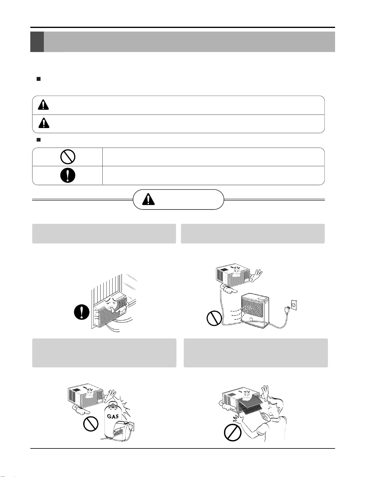
WARNING
Always install the expansion panel(s).
• Improper assembly or installation may cause
incorrect operation, including injury, fire, and
electric shock hazards.
Do not place the power cord near a heater.
• It may cause fire and electric shock.
Do not use the power cord near flammable
gas or combustibles such as gasoline,
benzene, thinner, etc.
• It may cause explosion or fire.
Do not disassemble or modify products.
• It may cause failure and electric shock.
Service Manual 3
Safety Precautions
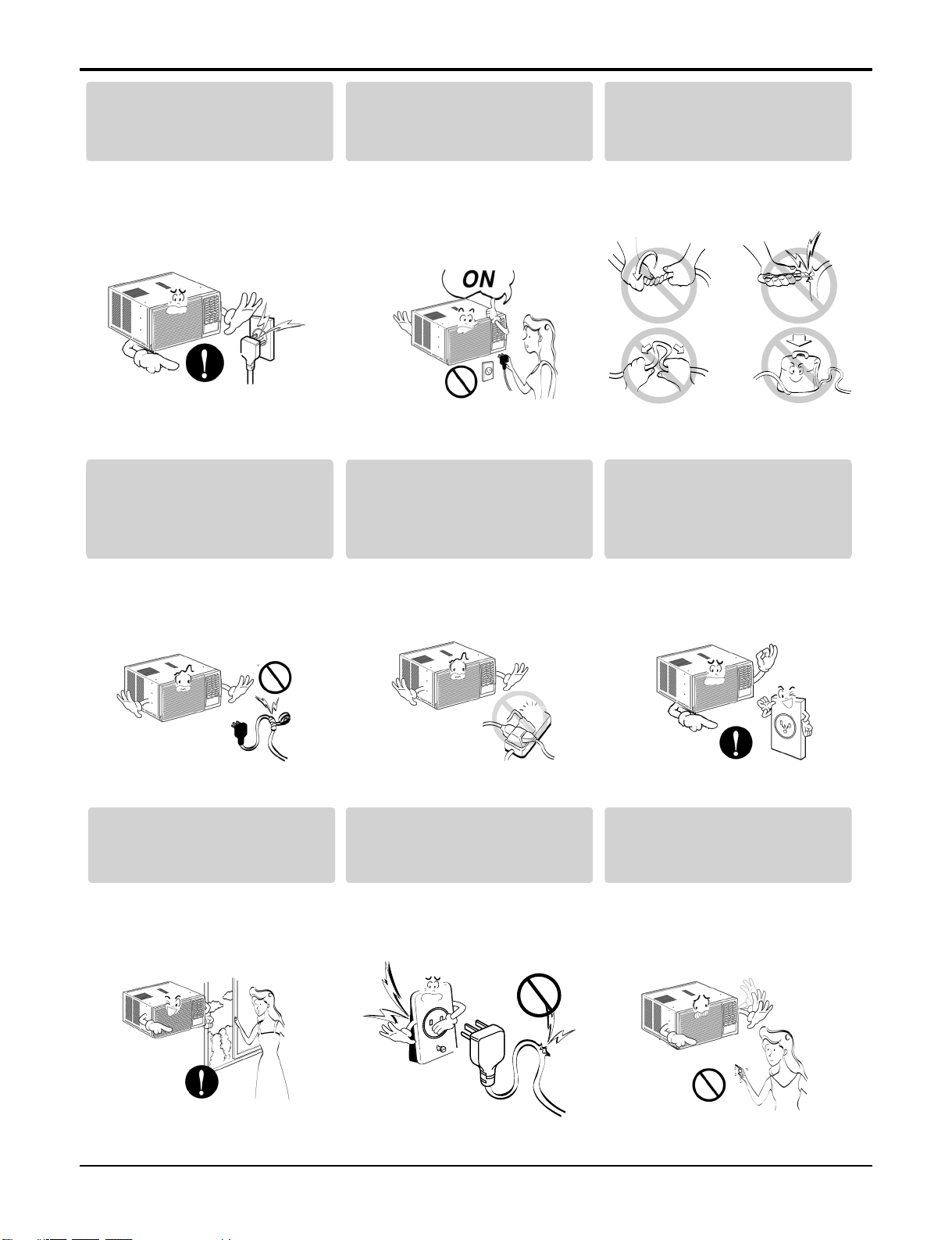
Plug in the power plug
properly.
• Otherwise, it will cause
electric shock or fire.
Do not modify power corDo not modify poDo not modify po dwer cor
Do not modify po
length.
Do not operate or stop the
unit by inserting or pulling
out the power plug.
• It will cause electric shock or
fire.
Use the air conditioner on a
single outlet circuit.(see page 7.)
Do not share the outlet with
other appliances.
Do not damage or use an
unspecified power cord.
• It will cause electric shock or
fire.
Always plug into a
grounded outlet.
• •• It will cause electr ic shoc• k or
fire.
Ventilate before operating air
conditionerwhen gas goes
out.
It may cause explosion, fire,
and burn.
•
It will cause electric shock or
fire.
Do not use the socket if it is
loose or damaged.
•• It may cause fire and electric
shock.
• No •• grounding • may cause
electric shock.
Do not operate with wet
hands or in damp
environment.
• It will cause electric shock.
4 Room Air Conditioner
Service Manual 5
Safety Precautions
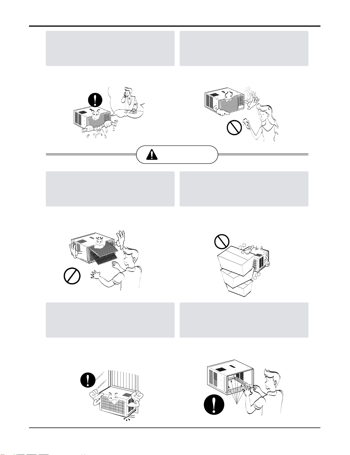
If water enters the product, turn off the the
power switch of the main body of appliance.
Contact service center after taking the powerplug out from the socket.
• It will cause electric shock or failure of
machine.
CAUTION
Never touch the metal parts of the unit
when removing the filter.
Do not clean the air conditioner with water.
• Water may enter the unit and degrade the
insulation. It may cause an electric shock.
Do not block the inlet or outlet.
They are sharp and may cause injury.
••
Ensure that the outer caseis not damaged
by age orwear.
Leaving it damaged couldresult in the air
conditioner falling out of the window, creating
a safety hazard.
It may cause failure of appliance or
•
performance deteriorate.
Be cautious not to touch the sharp edges
•
when installing.
It may cause injury.
•
Sharp
edges
6 Room Air Conditioner
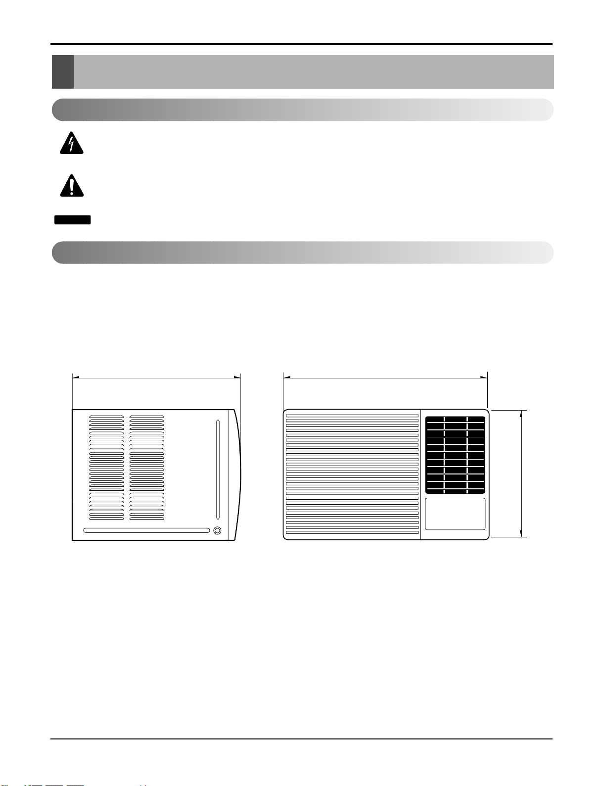
Dimensions
Dimensions
Outside Dimensions
This symbol alerts you to the risk of electric shock.
This symbol alerts you to hazards that could cause harm to the
air conditioner.
This symbol indicates special notes.
NOTICE
Symbols Used in this Manual
470(18 1/2")525(20 11/16")
/8")
7
353(13
Product Specifications
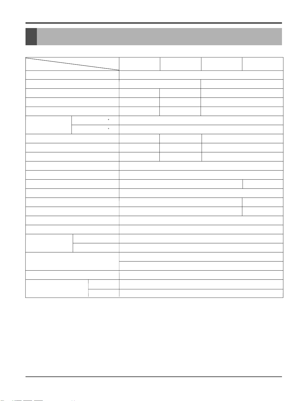
Product Specifications
Product Specifications
Product Specifications
Specfications
MODELS
ITEMS
POWER SUPPLY
COOLING CAPACITY (Btu/h)
INPUT (W)
RUNNING CURRENT (A)
.
.
E.E.R (BTU/W.h)
OPERATING
CONDITION
REFRIGERANT (R-22) CHARGE
EVAPORATOR
CONDENSER
FAN, INDOOR
FAN, OUTDOOR
FAN SPEEDS, FAN/COOLING
FAN MOTOR
OPERATION CONTROL
INDOOR ( C)
OUTDOOR ( C)
.
C)
BG8000ER WG8005R WG1005R WG1205R
1Ø, 115, 60Hz
8,000 10,000 12,000
740 1020 1220
6.8 9.2 11.0
7.6
10.8 9.8
9.8
385g(13.6oz) 260g(9.2oz) 440g(15.5oz) 380g(13.4oz)
Ø9.52, 2ROW 12STACKS
Ø7.0, 2ROW 16STACKS
.0
.0
.0
PROPELLER TYPE FAN WITH SLINGER RING
820
26.7(DB)* 19.4(WB)**
35(DB)* 23.9(WB)**
Ø7.0, 2ROW 14STACKS
Ø5.0, 2ROW 16STACKS
Ø
TURBO FAN
REMOTE CONTROLLER
Ø
7, 3R 14STACKS .7, 2R 14STACKS
Ø7, 2R 16STACKS 5, 2R 18STACKS
3/3
6 POLES
Ø
Ø
ROOM TEMP. CONTROL
AIR DIRECTION CONTROL
CONSTRUCTION
PROTECTOR
POWER CORD
DRAIN SYSTEM
OUTSIDE DIMENSION
(W x H x D)
H x
* DB:Dry Bulb
**
WB:Wet Bulb
COMPRESSOR
FAN MOTOR
(inch)
(mm)
THERMISTOR
HORIZONTAL LOUVER (UP & DOWN), VERTICAL LOUVER (RIGHT&LEFT)
SLIDE IN-OUT CHASSIS
OVERLOAD PROTECTOR
INTERNAL THERMAL PROTECTOR
3 WIRE WITH GROUNDING
ATTACHMENT PLUG (CORD-CONNECTED TYPE)
DRAIN PIPE OR SPLASHED BY FAN SLINGER
18 1/2 x 13 7/8 x 20 11/16 235/8x1431/32x225/16
469 x 353 x 526 380 x 600 x 555
Service Manual 7
Ser 7
Ser 7
7
8 Room Air Conditioner
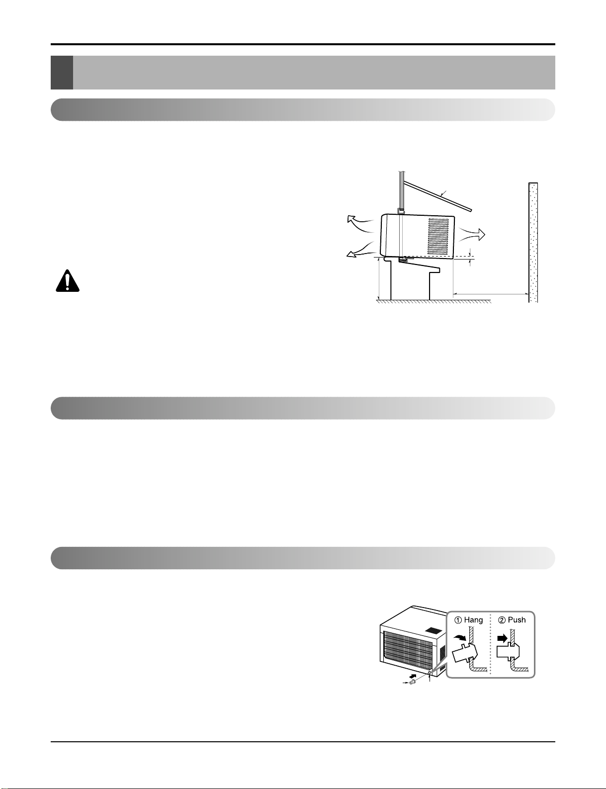
Installation
Installation
Select the Best Location
Installation Check
How to Secure the Drain Pipe
1. To prevent vibration and noise, make sure the unit is installed
securely and firmly.
2. Install the unit where the sun does not shine directly on the
unit.
3. The outside of the cabinet must extend outward for at least
11" and there should be no obstacles, such as a fence or
wall, within 20" from the back of the cabinet because it will
prevent heat radiation of the condenser.
Restriction of outside air will greatly reduce the cooling efficiency of the air conditioner.
CAUTION: All side louvers of the cabinet must
remain exposed on the outdside of the structure.
4. Install the unit slanted slightly so the back is slightly lower
than the front (about 1/
4"). This will force condensed water
to the outside.
5. Install the unit with the bottom about 30"~60" above the
floor level.
The setting conditions must be checked prior to initial starting.
The following items are especially important checking points when the installation is finished.
1. Grounding wire (Green or Green and Yellow) is provided in the power cord. The green wire must be grounded.
2. Connect to a single-outlet 15A circuit.
(or 20A circuit for Electric Heater Model)
3. To avoid vibration or noise, make sure the air conditioner is installed securely.
4 Avoid placing furniture or draperies in front of the air inlet and outlet.
In humid weather, excess water may cause the Base Pan to
overflow. To drain the water, remove the Drain Cap and secure
the Drain Pipe to the rear hole of the Base Pan. (Figure. 2)
ABOUT / "
Over 20"
HEAT
RADIATION
FENCE
AWNING
OUTSIDE
INSIDE
COOLED AIR
30"-60"
1
4
Drain Pipe
Drain Cap
Figure 1
Figure 2
Service Manual 9
Installation
How to Install
Window Requirements
All supporting parts should be secured to
firm wood, masonry, or metal.
1. This unit is designed for installation in standard double
hung windows with actual opening widths of 22" to 36".
The upper and lower sash must open sufficiently to allow
a clear vertical opening of 15" from the bottom of the
sash to the window stool.
2. If storm window presents interference, fasten a 2" wide
wood strip to the inner window sill across the full width of
the sill. The wood strip should be thick enough to raise
the height of the window sill so that the unit can be
installed without interference by the storm window
frame. See Figure. 4. Top of wood strip should be
approximately 3/4" higher than the storm window frame
(STORM WINDOW FRAME) or wood strip (OUTDOORS) to help condensation to drain properly to the
outside.
3.
Install a second wood strip (approximately 6" long by 11/2"
wide and same thickness as first strip) in the center of the
outer sill flush against the back off the inner sill. This will
raise the L bracket as shown Figure. 4.
4. If the distance between STORM WINDOW FRAME and
WOOD STRIP MOUNTED ON TOP OF INNER SILL is
more than 1", two of wood strip are not necessary.
Installation
NOTICE
OUTDOORSINDOORS
INNER
SILL
OUTER
SILL
INNER
SILL
WOOD STRIP MOUNTED
ON TOP OF INNER SILL
WOOD STRIP
FOR
L
BRACKET
3/4"
CLEARANCE
1" MAX.
STORM
WINDOW
FRAME
OUTDOORSINDOORS
OUTER
SILL
Figure 3
Figure 4
HARDWARE
Type A:16EA
(SCREW)
10mm
Type D:2EA
(NUT)
Type E:2EA
(FRAME CURTAIN)
Type B:3EA
(SCREW)
16mm
Type F:2EA
(SILL SUPPORT)
Type C:5EA
(SCREW)
Type G:2EA
(BOLT)
16mm
10
Type H:1EA
(FOAM-STRIP)
Type L:1EA
(WINDOW LOCKING BRACKET)
Type I:1EA
(UPPER GUIDE)
Type M:1EA
(FOAM-PE)
Type J:1EA
(FOAM-PE)
Type N:1EA
(DRAIN JOINT PIPE)
Type K:2EA
(FRAME-GUIDE)
(DRAIN WASHER)
Type O:1EA
10 Room Air Conditioner
Installation
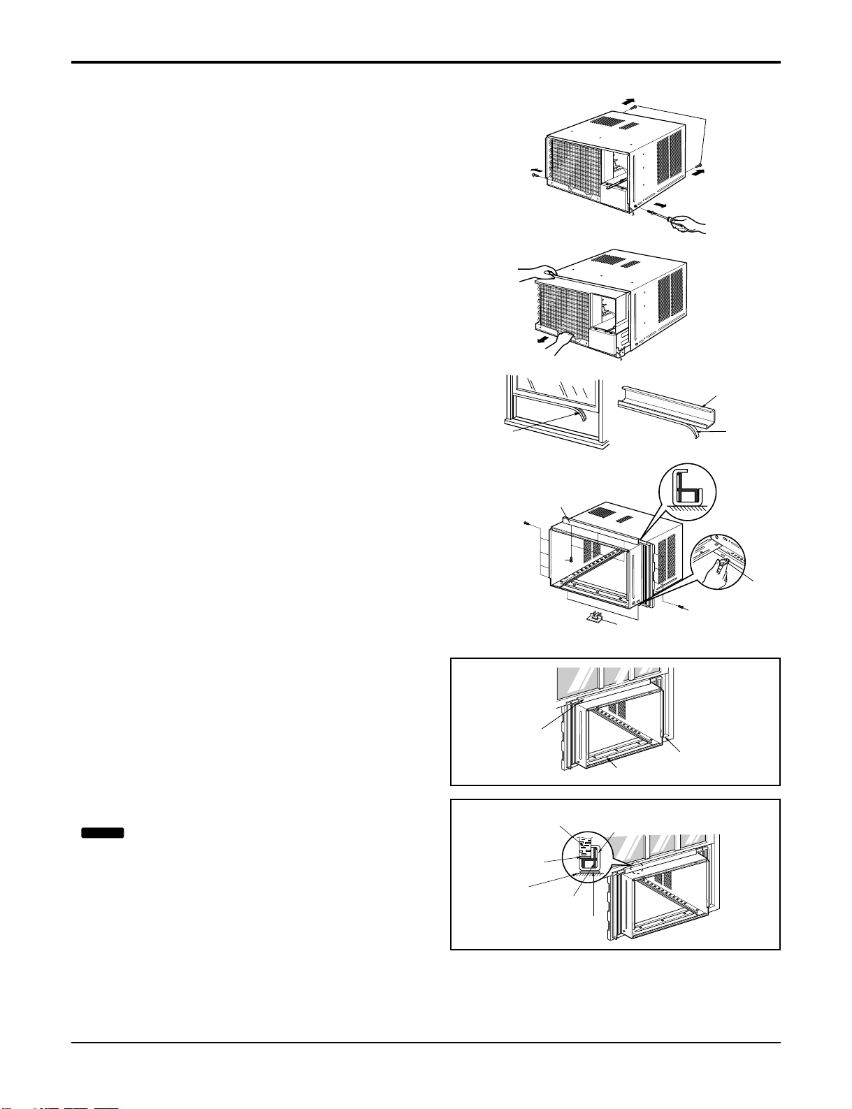
PREPARATION OF CHASSIS
1. Remove the screws which fasten the cabinet at both
sides and at the back.
2. Slide the unit from the cabinet by gripping the base
pan handle and pulling forward while bracing the
cabinet.
3. Cut the window sash seal to the proper length.
Peel off the backing and attach the Foam-Pe
to the
underside of the window sash.
4. Remove the backing from the top Upper Guide FoamPe and attach it to the bottom of the Upper Guide.
5. Attach the Upper Guide onto the top of the cabinet with
3 type A screws.
6. Insert the Frame Guides into the bottom of the cabinet.
7. Insert the Frame Curtain
into the Upper Guide
and Frame Guides .
8. Fasten the curtains to the unit with 4 Type A screws.
CABINET INSTALLATION
1.Open the window. Mark a line on center of the
window stool(or desired air conditioner location).
Carefully place the cabinet on the window stool and
align the center mark on the bottom front with the
center line marked in the window stool.
2. Pull the bottom window sash down behind the Upper
Guide until it meets.
Upper Guide
Upper Guide
Screw
Frame-Guide
(Type A)
Upper Guide
Window Sash
Window stool
Front Angle
Upper guide
Frame Curtain
Foam-pe
Foam-pe
Cabinet
Foam-Pe
Shipping
Screws
Figure 5
Figure 6
Foam-Pe
Frame-Guide
Screw
Screw
(Type A)
(Type A)
NOTICE
Do not pull the window sash down so tightly
that the movement of Frame Curtain is restricted.
Service Manual 11
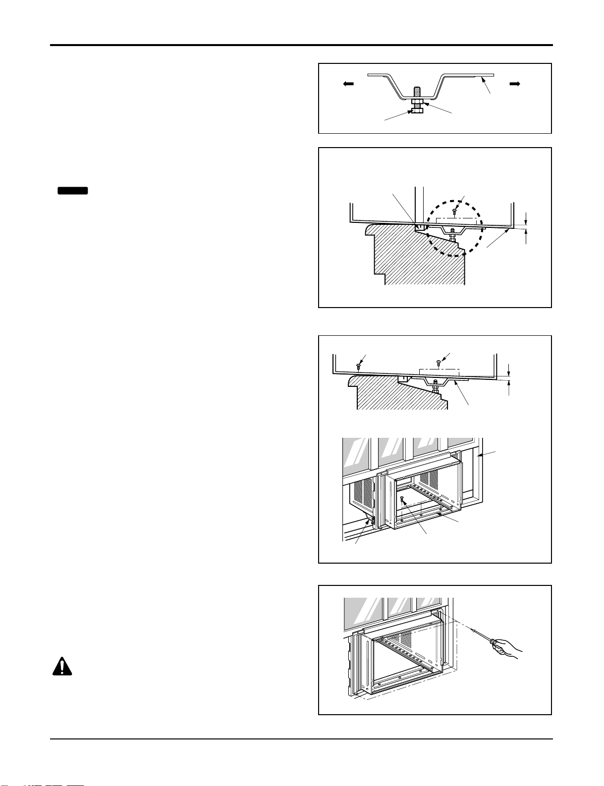
Installation
INDOOR OUTDOOR
Sill Support
Nut
Bolt
INDOOR OUTDOOR
Frame Guide
About 1/2"
Screw(Type A)
Cabinet
About 1/2"
Screw(Type B) Screw(Type A)
Sill support
Sash track
Front Angle
Type C
Screw(Type B)
Sill support
3. Loosely assemble the Sill Support using the parts in
Figure 7.
4. Select the position that will place the Sill Support
near the outer most point on sill (See Figure 8)
5. Attach the Sill Support to the cabinet track hole in
relation to the selected position using 2 Type A
screws in each support(See Figure 8).
6. The cabinet should be installed with a very slight
tilt(about1/2") downward toward the outside (See
Figure 9).
Adjust the bolt and the nut of Sill Support for
balancing the cabinet.
7. Attach the cabinet to the window stool by driving the
screws (Type B: Length sixteen millimeters and
below.) through the front angle into window stool.
8. Pull each Frame Curtain fully to each window sash
track, and repeat step 2.
9. Attach each Frame Curtain the window sash using
screws (Type C).(See Figure 10)
Figure 7
Figure 8
Figure 9
Figure 10
NOTICE
Be careful when you install the cabinet (Frame
Guides are broken so easily).
CAUTION: DO NOT DRILL A HOLE IN THE
BOTTOM PAN.
The unit is designed to operate with approximately
1/2" of water in bottom pan.
Screw(Type A)
Screw(Type A)
Power cord
Foam-Strip
Window Locking Bracket
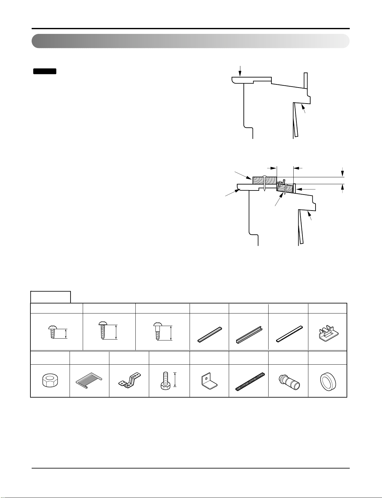
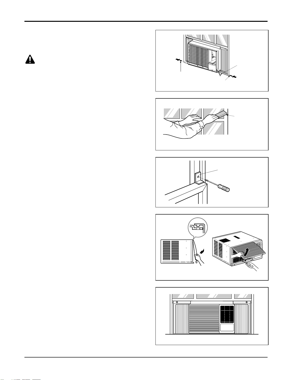
10. Slide the unit into the cabinet.(See Figure 11)
11. Cut the Foam-Strip to the proper length and insert
between the upper window sash and the lower
window sash.
(See Figure 12)
12. Attach the Window Locking Bracket with a Type C
screw. (See Figure 13)
13. Attach the front grille to the cabinet by inserting the
tabs on the grille into the tabs on the front of the
cabinet. Push the grille in until it snaps into place.
(See Figure 14)
14. Lift the inlet grille and secure it with a Type A screw
through the front grille.
(See Figure 15)
15. Window installation of room air conditioner is now
completed. See ELECTRICAL DATA for attaching
power cord to electrical outlet.
Figure 11
Figure 12
Figure 13
Figure 16
Figure 15
Figure 14
12 Room Air Conditioner
Installation
CAUTION: For security purpose, reinstall screws
(Type A) at cabinet's sides.
 Loading...