

GoldSt<tr
ELEKTITONIKK
CO.
&
ASK
LYNGBOVEII:N
t-nxst-'.vAc
55 34
48 93
TLF.
FAx
52
55
34
l0
i
I
OSCILLOSCOPE
SERVICE
os-g020P
MANUAL
€I
GoklStor
Jrrecision
Go.,LtGl.
GoldSt<tr
OSCILLOSCOPE
SERVICE
ASK
TLF.
os-g020P
MANUAL
& CO.
E l
ss
I'I,I.]KT'RONIKK
LYNGB['VEIEN 52
t.nxsr.vAc
ti
4tt
34
FAX
93
troRwA
y
s-5 34
1l
10
M
OoklStcrr lrneclslon
#20,
Yoido-dong,
19th
Fl.,
Yoido
Tel:(02)
Fax:
East
P O.
787-6862
(02)
7 84- 1 646,1
Gold5tctr
13013
East 166th Street
Tel:(213)404-0101
(213)921-6221
Fax:
Tlx;B'l
Q-563-57 1 I
Yongdungpo-gu.
Tower,
Box 4Q4
Lucky-Goldstar
6828
-681
87
frreclslon
LGILA
Seoul
Twin
Ttx:GSFADAR
8 Cable
Cerriors,
:
GOLDRADAR
Ca,90i01-2226,
Go-,Ltcl.
'l
80-121,
Towers
K22938
Korea
U S A
Servicing
Precautions
Please read alI instructions
before
Disconnect
enclosure.
Instructions
1. To naintain the
2. After turning on
3.
4. For
Warranty
servicing.
power
before use.
Triple-Iine
are using the doubleline
of
product
product
the
quality
can be changed without
cord fron
precj"sion
power,
power
inprovenent
cord
to the
earth at the
in the
power
and reliabili.ty
please
is to
cord, make sure to
the exterior
service rnanual throughly
source before
allow a
be used for the
power
design and
prior
notice.
opening the
of the
1S-ninute
product.
connect
source
product
per-heating
for safety.
specifications
use
But when
the earth
it.
period
you
terninal
of
the
Warranty
purchase.
In case of
provided
We charge
when the
accident, we
Notice
This
there
If
servi.cing
service covers
technical failure
by our service
for
failure is a result
Serivce Manual
are
unit,
period
a
center.
repairs after
charge for
any specific differences
please
repairs
describes
contact
(iol-dStar
of
within
the
one
of user's
regardless
the
most typical
GoIdStar Precisj.on
Preci-siorr
year
one
year,
one
year
neglect,
between
fron the
repair
warranty
natural
of
the warranty
product
this
date of original
service
period
Manua] and
Co.. Ltd.
expires.
disaster
of this
Co-,
wiII
period.
model.
the
I-td.
be
or
-2-
CONTENTS
]-. SPECIFI
ACCESSORIES
2.
PREVENTI\/E MAINTENA\ICE
3.
4.
CIRCIJIT
5. CAI-IBRATI
Calibration
5-1.
Test Equipment
5-2,
Prelininary
5-3.
Prelininary
5-4.
Initial Starting
5-5.
CATI
DESCRIPTION.
Interval ..
Procedure ..
Control Settings
ON
.
ONI
Required
Procedure
....
.......
7A
13
13
13
13
14
14
SEMI COI\IDtTCTOR
6.
CONFI GTIRATI
7- EI-ECTRI
(WITFI
EI-ECTRI
A-
BI-OCI{ DIAGRAM.
9.
Lg.
1- 1-. WIRTNG DIAGRAM .
L2.
A3.
SCI{EMATIC
MECFIANI
vI EW
EX:TERNAI-
CAI-
ADJTISTMENT I-OCATIONS)
CAI-
CAI-
()1\I
PARTS ARRAAIGEMEIVT
PARTS
DIAGI?AMS
PARTS I-I
VIEWS
I-EAD
I-I
ST
ST &
.......
EXPI.-ODED
24
25
27
43
44
58
59
62
-4-
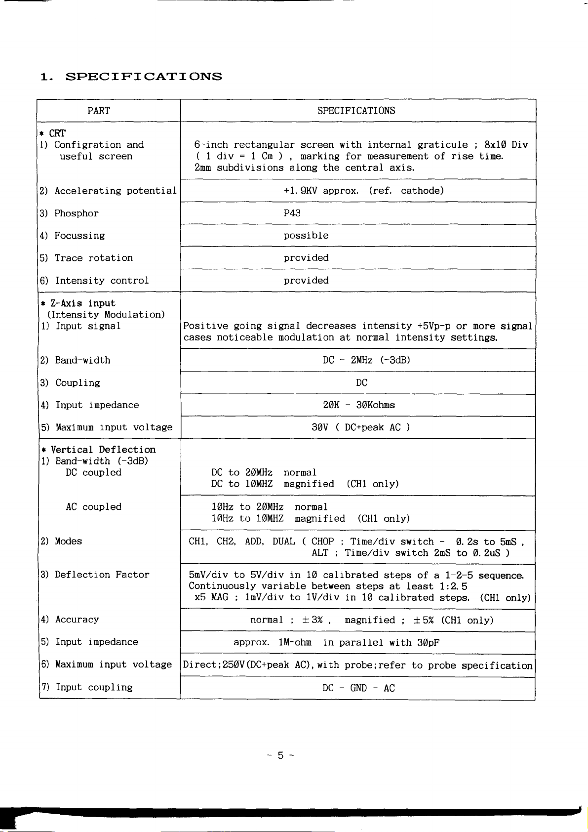
1.
SPECIFICATIONS
PART SPECIFICATIONS
'
CRT
1) Configration
useful
screen
and
6-inch rectangular screen with internal
(
1 div = 1
Znm
subdivisions
Cn
) ,
along
marking
for
the centraL axis.
neasurenent of
graticule
rise
8x10
;
tine.
Div
Accelerating
2)
Phosphor
3)
Focussing
4)
Trace
5)
Intensity control
6)
r
Z-Axis input
(Intensi
Input signal
1)
Band-width
2)
Coupling
3)
Input inpedance
4)
Maxinun
5)
r
Vertical
Band-width
1)
rotatj.on
Modulation)
ty
i"nput voltage
Deflection
DC coupled
potential.
(-3dB)
+1.9KV
approx.
(ref.
cathode)
P43
possible
provided
provided
Posi.tive
going
signal decreases
intensity
+svp-p
or nore
cases noticeable nodulation at nornal intensity setti.ngs.
DC - ZMHz
(-3dB)
DC
-
DC to
DC to
ZAMHz
IAMHZ
ZAK
30V
nornal
magnified
30Kohns
pQ+pgak
(
(CH1
AC
only)
)
signal
coupled
Modes
Deflection Factor
4) Accuracy
Input
5)
Maxinun input voltage
6)
7) Input
inpedance
coupling
to
LbHz
lAHz
ZLllHz nornal
to
MlllHZ nagnifj.ed
(CH1
only)
CHl, CHZ,ADD. DUAL ( CH0P ; Tine,/div switch
SnV./div
to
Continuously
x5 MAG
;
approx.
DirectiZSAV
ALT ; Tine,/div
SV,/div
in
variable
10 calibrated
between steps
lnV,/div to 1V,/div
nornal
(Dc+peak
x3% magnified
lM-ohn
in
AC), with
in 10 calibrated
paralIeI
probe;refer
switch
steps of
at
least I:2.5
t 5%
with
to
DC-GND-AC
-5-
-
A.Zs to
ZnS to 0.ZuS
a l-2-5 sequence.
steps.
(CH1
(CHl
only)
30pF
probe
specification
5nS
)
only)
,
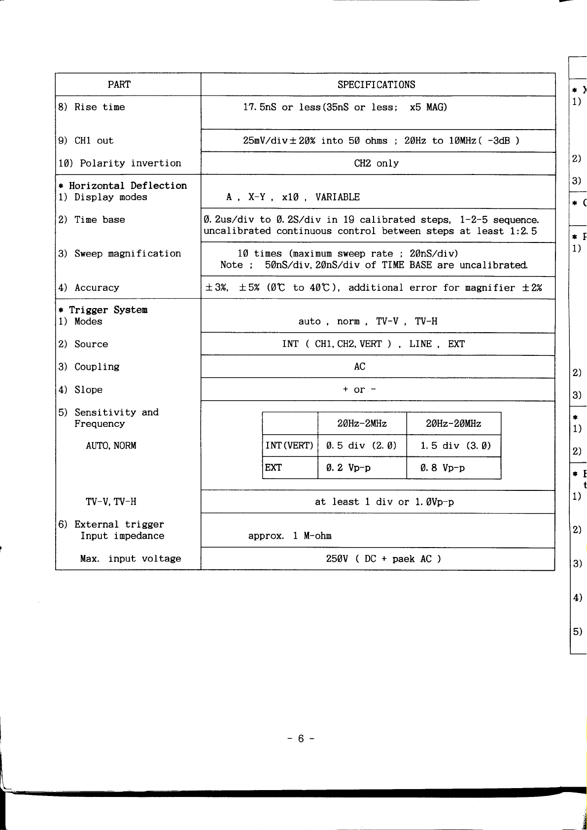
Rise tine
8)
PART
17.5nS
or
less(35nS
SPECIFICATIONS
or less; xb MAG)
;
1)
9) CHl
10) Polarity
r
1) Display nodes
2)
3) Sweep
4) Accuracy
r
1)
2) Source
3) Coupling
4)
5) Sensitivity
out
invertion
Horizontal Deflection
Tine base
nagnification
Trigger
Modes
Slope
Frequency
Systen
AUTO, NORM
TV-H
TV-V,
and
Z5nV/divXZA%
A X-Y
b.2us/div b
uncalibrated continuous
10 tines
Note
;
t3%,
f.5%
xlt
,
A.ZS/div
(naxinun
50nS,/div.ZLnS/div of
QC
INT
(VERT)
INT
EXT
into 50 ohns
VARIABLE
to 40C), additional error for nagni.fier
auto,
(
CH1, CHz, VERT
4.5 div
0.2
at Least 1 di"v
ZAHz
only
CH2
in 19 calibrated
control between steps
sweep
norn,
20Hz-ZMHz ZAHz-ZAMHz
rate ; ZLnS/div)
TIME BASE
TV-V, TV-H
)
AC
for-
A)
Q.
llp-p
LINE
or 1.
t0llHz(
to
steps,
are uncalibrated.
EXT
,
1.5 div
0.8 Vp-p
0Vp-p
-3dB
)
L-2-5 sequence.
at least
(3.0)
1:2.5
t2%
2)
3)
tC
t,
1)
2)
3)
I
1)
2)
rE
t
1)
External trigger
6)
Input
Max. input
inpedance
voltage
approx. 1 M-ohn
250V ( DC
+
paek
AC
2)
)
3)
4)
5)
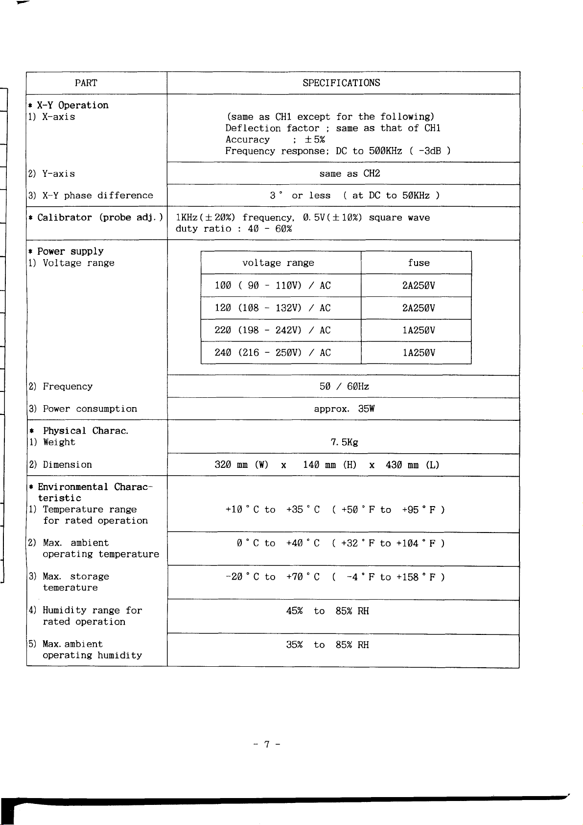
PART
*
X-Y 0peration
1) X-axis
(same
Deflection
Accuracy
Frequency
as
SPECIFICATIONS
except
CHl
factor
;
response;
;
X5%
the following)
for
as that
sane
DC to SAAKHz
of
(
CH1
-3dB
J
Y-axis
2)
phase
X-Y
3)
*
Calibrator
*
Power
l) Voltage
2) Frequency
3)
t
1)
supply
range
Power
Physical Charac.
Weight
consunption
difference
(probe
adj.) \KHz(+ZAD frequency,
duty
3'
ratio : 40
-
6A%
voltage
lAA(90-rlgv)/AC
-
(108
r20
229
244
(r98
Qrc
r32V) /
-
242V) / AC A25AV
-
Z50V) /
sane
as cHz
or less ( at DC to
0.5V( XLT%)
range fuse
square wave
50KHz
2A25AU
AC
AC
zA25AV
Az5AV
5A / 6AHz
approx.
35W
7.SKe
)
t\
Dimension
r
Environnental
teri
1) Temperature range
for rated operation
2) llax. ambient
operating tenperature
3) Max.
tenerature
4)
Humidity range
rated operation
Max.
5)
operating
c
sti
storage
anbient
Charac-
for
humidity
nn
320
+10'
0'C to
-2A"Cb
(W)
to
C
-7-
l4A
x
+35' C (
+40" C ( +32
+7A"C (
45% to
to
35%
(H)
nn
+50'F
-+"Fto+158'F)
85%
85% RH
x 43A
'F
RH
to
+104'F
to
(L)
mn
+95'F
)
)
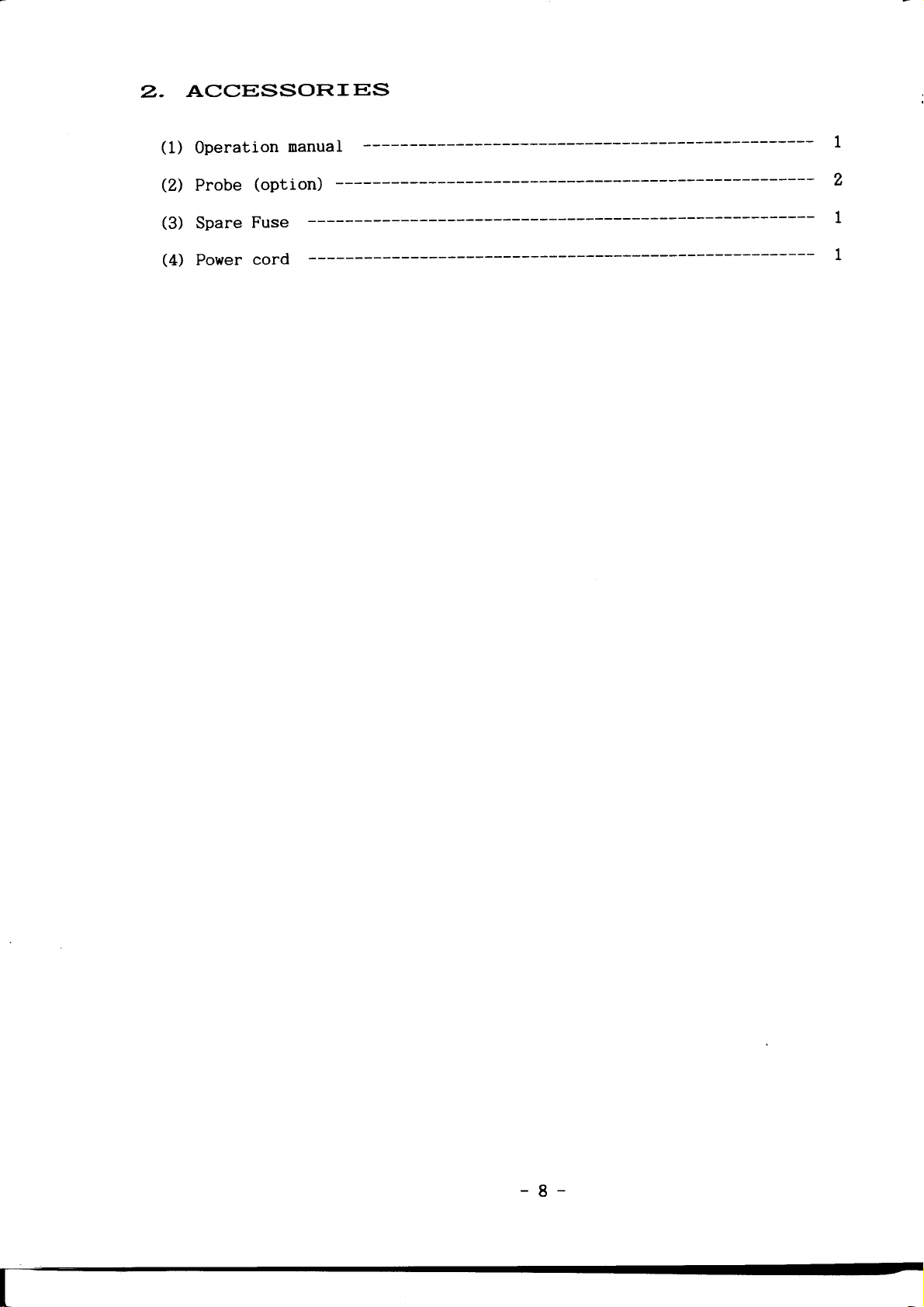
ACCESSORIES
2.
(1)
Operation
(2)
Probe
(3)
Spare
(4)
Power
nanual
(option)
Fuse
cord
-8-
PREVENTT
3-
VE
MAT
NTENAAICE
Preventive maintenance,
instrunent breakdown and
The severity of
deternj.ne the
preventi.ve
Disassenbly
Renove
the
parts
Cleaning
The
require. Accumulation of dirt
breakdown.
The
instrunent. Loose
a soft
Dirt that renains
detergent
Cleaning
way
velocity strean
applicator
delicate
maintenance
the screws in the top
top cover
of the instrunent are
instrument should
covers
cloth or
the interior should
to clean the
conponents.
environnent
frequency of
fron
provide
snall brush.
water
and
of air. A soft-bristle
is useful
when
is
the instrunent and
be cleaned
protection
dust accunulated on
be
can
solution.
interior
for
perforned
may
improve the
to
which this
naintenance.
preceding
cover of the
now accessible.
in the instrument can
against dust in the interior of
removed with
Abrasive
only
is
to
cleaning
on
a regular
reliability of the oscilloscope.
instrument is
A
convenient tine to
recalibration
instrument.
Iay
aside.
as often
be occasionally
blow off the
in
as operating conditions
these covers
a soft cloth
cleaners should
brush or a cottontipped
narrow spaces
of
dust
basis, can
subjected
the instrunent.
Gently
Most
of
cause component
can be renoved with
danpened in a nild
not
necessary.
with
a dry, low-
or for cleaning
prevent
perform
seperate
the
internal
be used.
The
will
the
best
nore
Visua1
The
brocken
boards,
visible
if
other
the
Inspection
instrunent
heat-damaged
overheating
should be inpected
connections,
and heat-danaged
defects
trouble
is apparent
conponents
in the
is inportant
improperly
parts.
;
are
instrument
to
occasionally
seated
the corrective
however,
found.
;
prevent
transistors,
particular
Overheating
therefore,
-9-
for
procedure
correcting
recurrence
such defects
danaged circuit
for nost
care
nust
usually indicates
the
of the
damage.
as
be
taken
cause
of

4. CIRCT]IT
The block diagran
the
of
section schnatics diagrans
Refer
electrical
circuits.
to these
values
DESCF?IP:trION
(
page
Conplete
diagrams throughout
and relationship.
43
shows the overall
)
schematics
(
page
44 to
the
relationship
of
each circuit are also
57
).
following circuit description
between
given
all
in
for
ATTENUATOR
Signals
applied
to the input
or they can be disconnected
position.
GND
Attenuation
The attenuator
+lA,
+2,
are
+tAA circuit.
+4,
between
CH1 ( CHz
Signal
(
0105
follower, the
Q101 ( 0105
is feed
by 5 tines.
Q104
the signal of
And
paraphase
to a
is deternined
by the setting
that is controlled
=10 circuits are in RA101
S101-AZ ( StgZ-AZ ) and
IT.TPUT A}IPLIFIER
)
fron the input attenuator is connected to
When
).
back to
excessively high-anplitude signals are applied
signals wiII be
When
).
5801
AMP through
0P
QZAG ( 0306
signal by differential
is open
(1)
connector
+he
to
can be either
internal circuit
the
of
by the
VlLT
/
(
RAIAZ ) and =10, +LAA
5101-82 ( SLg2-82
(2,3)
Q103 ( 4106
(
x
SMAG
R109 anplfies the output
base is converted
)
anplifier.
and
)
the signal that
),
coupled
AC
when 5901
(
V1LT / DIV switch.
DIV
switch has
;2,
circuits
).
source follower
to
gate-source
the
signal of
fron a single-ended
or DC coupled,
5902 ) is
+4,
Q101
the
source
junction
of
simal
CH1 ( CHz ) PREAilP &
Vertical
They also contain a stage to
trigger
only. And the trigger
horizontal
The trigger
level necessary to drive
preanp
preanp
VERTICAL
The vetical switching
input signals to be
Input signal
that is controlled
the TIME / DIV
In
shared
ALT
the
tine basi.s.
circuits
circuit for
anplifier
preanp
CON'IBOL
combinations
switch.
and
CHOP modes, both channels
TRIGGER
provide
preamp
in the X-Y
circuit
the
circuit
connected
that
by the vert.ical
PICK
OFF
control
provide
internal triggering fron
of
anplifies the
trigger
determines the
to
can
a sample of the
provides
CH1
position
generator
vertical
the
be displayed
node switches
_IA_
vertical
of
the
CH1
the
of
internal trigger signal
are alternately
TIIIE
circuit.
input signal or
nain
are selected
and the
position.
input signal
the
CH1 or
input
/
anp.
simal to the
DIV switch.
X-Y
displayed
to the
signal
CH2
to the
conbination
by
D
FLIP-FLOP
position
on
of
a
of
VERTICAL MAIN AMPLIFIER
(7
)
The vertical nain amplifier
the vertical deflection
deflection
TRIGGER
The Trigger Anplifier circuit
generator
The Trigger
node switch, TV synchronization
The Trigger
etc.
vertical trigger
external trigger input BNC connector
The Trigger Generator Circuit has the circuit to
and slope.
The signal type is AC.
The Trigger mode
ci rcui t.
In the N0RM node, the sweep
generated,
is
as N0RM mode, except that a
pulse
The Base Signal of
is amplfied
etc
The anplfied signal, the collector
U109,
The N0.8
outputs in
plates
AMPLIFIER
circuit.
is
not
pin
of the
Generator
Source Switch
preanps, power
Switch
0peration in
present
Q130
by
Q345, Q346.
N0.8
signal
of
circuit consists
or the
pin
U109
circuit
signal before
CRT.
produces
determines the operating
signal
the
free running trace is displayed when
aplitude of
which
enters through three switches,
of
U109.
is called
provides
it is
trigger
of the trigger
circuit, trigger
selects one
line source
connected to front
generated
is
AUTO, TV-V mode is the
signal of
trigger signal
the
applied
signal of
applied
the trigger
Q346,
final
naplification for
the vertical
to
(8)
pulses
amplifier, U109
control the trigger
mode for the trigger
only
enters the N0.2
start
to
source, trigger
the signals fron the
to
this instrument,
panel.
the trigger signal
sane
signal
trigger
or
the sweep
operation
is not adequate.
Q34?
and
level
a trigger
and
pin
pulse.
generator
of
SWEEP GENERATOR
Sweep
The sweep
the
The signal in the
amplified sj.gnal appear
enters the Base of
This sweep signal is
generator
The sweep
sweep
generator
gate
of
time.
gate
Q129,
circuit.
gate
circuit consists of
on, a very
is
input
gate
Q327
generated
circuit
-
gate
Q342,
(
11
sweep
little
Miller Integrator, by
of
Q129
in
the Enitter of
through R551.
produces
negative
is anplified
on comnend
an unblanking
(9)
circuit
going
R-C network.
by Miller
is ca]Ied
trigger
gate
-
and niller
signal
pulse
to unblank
is
Integrator,
sweep signal
)
integrator.
generated
the
fron
the
the
CRT during
in
and
trigger
HORIZOT.ITAL
The
Horizontal
drive the
The
Horizontal
The
first stage
require
output
The
ouput signal
horizontal
The output
horizontal
The Horizontal
horizontal
In
all
of the
generator.
signal
preamp
CRT horizontal
very little
change.
deflection
signal
deflection
position
position
horizontal
In the
of the
circuit
OUIPIJT AilPLIFIER (12)
main
change
DIV
/
of
deflection
provides
plates.
consists
anplifier
at the
arnplifier
anplifier
has
the
select
is the
the
TIME
Anplfier
the
final
of
five
has a low
input to
}IZS,
e126,
horizontal
switch
sawtooth
DIV
/
is
the signal
systen.
except
Output Anplifier
deflection
0utput Anplifier
horizontal
voltage
fron
cornplenentary
plate.
from
Output Anplifier
of the
output
X-Y
Horizontal
of
the vertical
conplenentary
p1ate.
functions.
TIIIE
anplifier
position
Output
signal
cascade
produce
Q127
stage
input
drives
Q128
magnification
X-Y the
signal
select
switch
fron
anplification
anplifiers.
inpedance
the
desired
the
drives
from
the
the
and
input signa]
the
sweep
the
input
channel
to
and
right
left
the
I
POWER
The
Volts,
source
systen,
STIPPLY (14)
Iow voltage
*5
( +195
horizontal
CRT CIRCUIT
The
CRT
Circuit
The
circuitry
high voltage
The
calibrator
amplitude
This
output
(
II{Ilz
and
connector.
)
Power
Volts,
volts
provides
consists
regulator,
circuit
frequency.
signal
Supply
+12 Volts,
used to
)
deflection
the voltage
of
the z-axis
high
produces
available
Circuit
*56
operate
systen
woltage
square
a
as
a square
provides
Volts,
the
and
levels
amplifier,
rectifier
five
+I4A
vertical
driving
cRT
and control
and the
wave
output
wave
Voltage
regulated
Volts
deflection
(13)
high
sources
and
)
three
circuit.
circuits
voltage
CRT controls.
signal
at
with
the
oscillator,
PROBE
-tz
(
unregulated
to
operate
accurate
ADJUST
0.bVp-p
CRT.
-t2-
5. CAI-IBRATI
ON
GoldStar Precision
Contact
5-1. Calibration
To
at least
if
5-2.
The
equivalent,
The
for
Therefore,
exceed
All
operating within
test equipnent
nanual
the
GoldStar Precsion
naintain
used frequently.
Test
following
given
accurate
the list
the test equipment
instrunent
every
equipment required
test
are requl.red
specifications
calibration.
the
for the
Ltd.
Co.,
interval
accuracy,
TAAA hours
equipment(Table
for
for
specifications
specifications.
ia assuned
the
Iisted
are not
test
given
equipnent
provides
Co.,
of
the
specification.
Ltd.
perforn
operations
5-1
complete
the test
of any
to
in this
if nore
conplete
office.
the calibration
or every
see
;
calibration
equipnent
test
equipment
be
comectly
Operating
procedure.
information
instrunent
six nonth
page
23) and
are
the ninimun
used
calibrated
Refer
is needed.
repair
of
the
accessories.
of the
instructions
to
0S-9020P.
nust
neet
and
the
inst,ruction
and calibration.
OS-}AZ4P
or
necessary
or
for
the
Prelininary
5-3.
This
instrunent
(
t 5C
1.
Connect the
2.
Set the instrument
Setting.
3.
See the
)
procedure
should
for
best overall
instrunent
Allow at
Adjustment
be calibrated
accuracy.
to
AC
controls
least
Locations
fifteen
at an anbient
Iine voltage,
given
as
minutes
in the
in the
pulrout
tenperature
Sa/6aHz
preliminary
of warnup
pages(see
of
line source.
Control
before
proceeding.
page
2E).
+ZAC
-13-
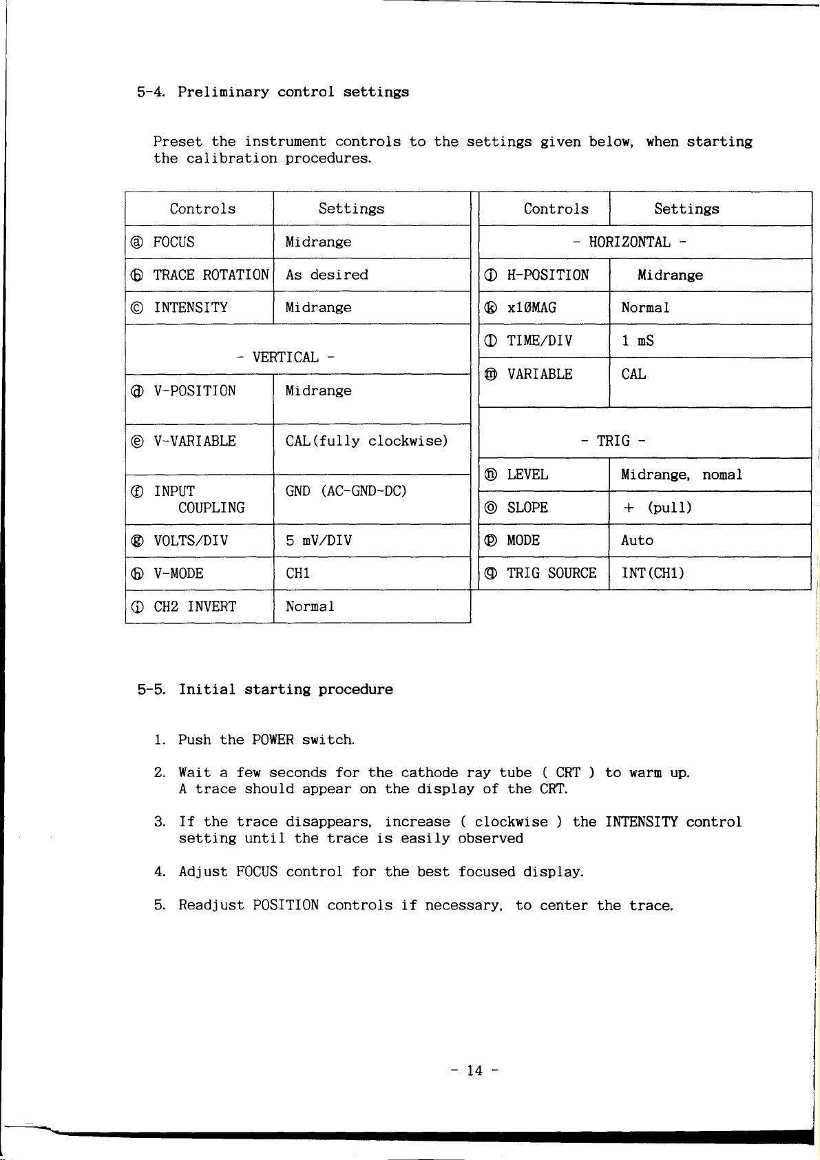
5-4.
Preliminary
control settings
Preset the
the calibration
instrument controls
procedures.
the settings
to
Controls Settings Controls
Focus Midrange
@
TRACE ROTATIONAs
O
INTENSITY
O
-
VERTICAL
desi.red
Midrange
_
o
(E
O
@
V-POSITION
@
V_VARIABLE CAL(fully
@
Mi drange
clockwise)
@
@
INPUT
COUPLING
(AC-GND-DC)
GND
@
given
below,
when
starting
Settings
-
HORIZOI'ITAL
-
H-PosrTrON Midrange
x1OMAG Normal
TIME/DIV
VARIABLE CAL
-
LEVEL Midrange, nonal
SLOPE
1nS
TRIG
+
-
(putt)
VOLTS,/DIV 5
@
V_MODE
O
INVERT Nornal
CHz
C
Initial
5-5.
1.
Push the POWER switch.
2.
Wait a few seconds for the cathode ray tube
A trace should appear on the display of the
If
setting
4.
Adjust F0CUS
the
trace
Readjust POSITI0N controls if necessary, to
starting
disappears, increase ( clockwise ) the
until
the trace is
control for the best focused display.
mV,zDIV
procedure
easily
MODE Auto
@
TRIG
@
observed
SOI'RCE
(
CRT
CRT.
center
(CH1)
INT
to warm up.
)
INTENSITY
the trace.
control
POWER
STIPPLY
SYSTEM
NOTE
: Before
(see
Control
Preset the
Check
t1l
a.
b.
c.
d.
e.
f.
Check
lU
a.
b.
you
page
settings
controls as
Low-voltage
Connect
Connect
Connect
Connect
Connect
Connect
High-voltage
Connnect
High-voltage
by
Check
begin,
see ADJUSTMENT
25)
given
Supply, if necessary.
the digital voltneter
:
*11.75V
the DVM fron
in
to
the - 12 volt line.
: - 11.75V to
the DVM fron
1.4.
?5V
:
the DVM from
:
*54V to +58V
the
DVM fron the
:
*137V to *I42Y
the
DVM fron the
+185V
:
the DVM
DVM
for
reading
Probe.
the * 5 volt ]ine.
to
+5.25V
the *56 volt I ine.
+2lAY (JlA)
to
Supply.
the
to
as
the
Prelininary
+I2.25V
-I2.25U
+ t4g
+195
volt
H. V test
-1705
LOCATI0NS in
Control
(
DVM ) from the
volt
line.
(unregulated)
(
H. V and
point
-
line.
-1895V
pullout
the
Settings.
* 12 volt line.
(
PB101-9
(
P8101-6
(
PBL0I_T2
(
R183-down
(
R183-up
DRV
CRT
(P106-6)
pages.
)
)
)
)
)
BD)
Control Setting
Preset
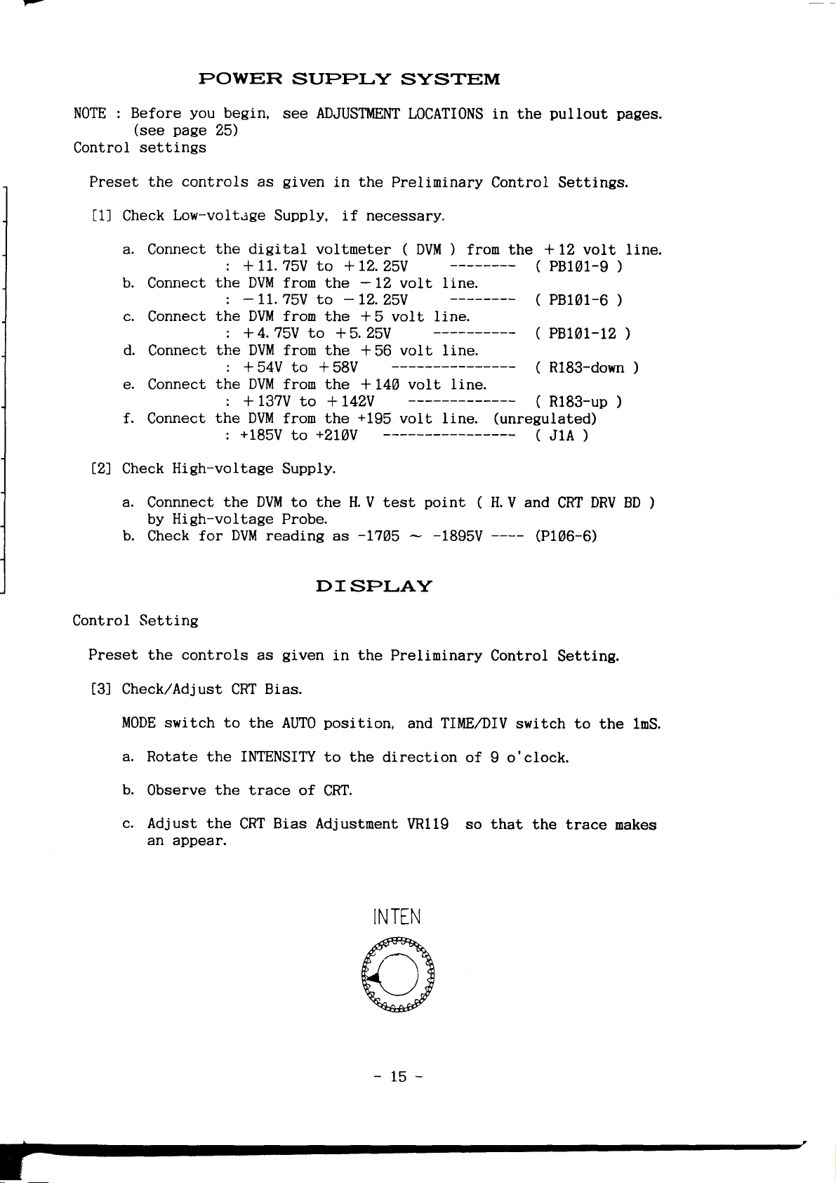
Check,zAdjust
t3l
the
controls
MODE switch to
a. Rotate the
b.
Observe
c.
Adjust the
an appear.
DI
given
as
Bias.
CRT
the
AUTO
INTENSITY to the
the trace
CRT
of
Bias
Adjustment
SPI-AY
the
in
position,
direction of
CRT.
INTEN
Prelininary
and TIME,/DIV
VR119 so that
Control
switch to
I o'clock.
the trace
Setting.
the lnS.
makes
-15-
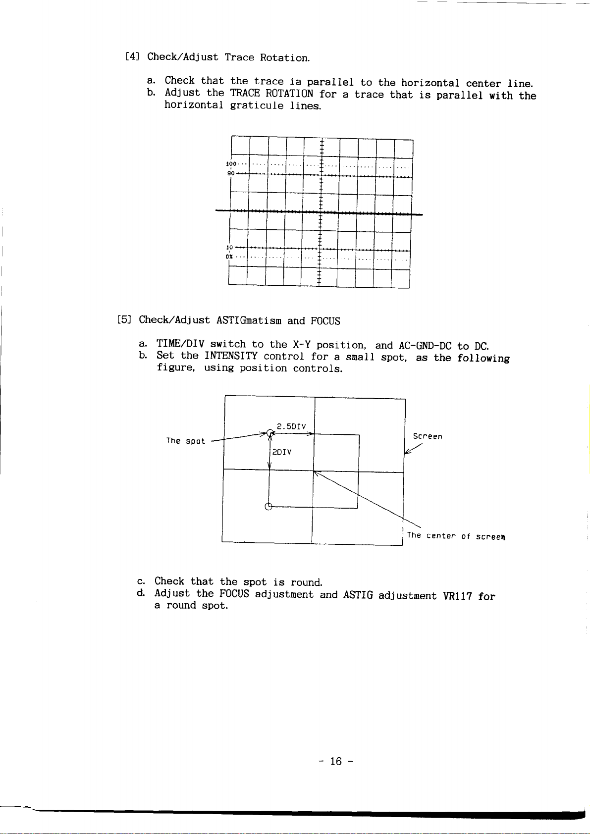
Check,zAdjust
t4l
a.
check
b.
Adjust
horizontal
Check,zAdjust
tsl
a.
TIME,/DIV
b.
Set the
figure,
Trace
that the
the TRACE
trace
graticule
ASTIGnatisn
switch
to
IIITENSITY
using
position
Rotation.
ia
R0TATION
lines.
and
the
X-Y
control
controls.
parallel
for
FOCUS
position,
for
a
to
the
a
trace that
and
snall
spot,
horizontal
parallel
is
AC-GND-DC
as the
to
following
center
with
DC.
line.
the
The
c.
Check that
d.
Adjust
a round
spot
the
the
FOcus
spot.
spot
is round.
adjustnent
and
ASTrG
center
adjustnent
of
vRll?
scneel
for
-16-

I{ORI
ZONTAI-
SYSTEM
Control
Preset
t6l
l7l
t8l
settings
controls
the
Check,/Adjust
a. Set
b.
c. Check
d.
the input AC-GND-DC
TIME,/DIV
that
center
Adjust
eight DlVisions,
the H GAIN
with the center
Check,zAdj
a. Set
b. Set
c. Check
ust
the TIME,/DIV
x
10 MAG
that
graticule
Adjust
d.
time
Check,zAdj
Set
a.
Being the
b.
the MAG GAIN
marks align
ust
the TIME,/DIV switch
the Ieft
the x1OMAG
then
Observe
Adjust
d.
end
the
the MAG CENT
of the
as
given
the Prelininary
in
Horizontal Gain.
to DC.
switch
to the Lms.
the time narks align
within
adjustnent VR114
eight
Horizontal
one-cycle tine narks
the
lines,
graticule
x
10 MAG
switch
to the 1mS.
within 5%.
adjustnent VR115
with the
MAG
CENT.
to the
x1OMAG
end of
novenent of
switch
the trace is brought
switch
to the
to the
the left end
adjustment VR116
trace within t
with the
3%
so that
lines.
Gain.
align with
ten division
1 nS.
0.
x1OMAG,
position.
xl
A.ZDIV.
Control
graticule
the
Settings.
line over the
tine narks align
the ten
so that
graticule
to the center
the one-cycle
Iines.
point
of the trace.
for the movenent
division
and
of the
Check,/Adj
t9l
a.
b. Set
c. Check that
d.
Check,zAdjust
i10l
a. Set
b.
c. Set
d. Check that
e. Adjust
ust low
the tine mark
Set
spaced sweep accuracy.
generator
the TIME,/DIV swi.tch
tine narks
the
niddle eigth
Adjust the
with the middle
divisions,
SmS,zDIV
adjustnent VR106
eight
High speed
graticule
sweep accuracy.
the input coupling switch to
Set
the
time
nark
generator
the TIME,/DIV switch to
the tine marks align with the
the middle eight
VC113
graticule
Iines.
division.
that the time narks coincide whth niddle eight
for
to
5mS.
align
within
for 10
the
-77-
tine narks.
5mS
with the
3%
so
lines.
DC
p
S tine narks.
10 r S.
graticule
line
over
the
that the time narks coincide
graticule
lines over
\/ERTTCAI-
SYSTEM
Control
Preset
tlll
ll2l
settings
the controls as
Check,zAdjust
a. Set
b.
c. Change
d.
e. Adjust
f.
Check,zAdjust
a.
b.
c.
d.
e.
f.
the
VoLTS,/DIV
Position the
the VOLTS,/DIV switch to the
Check
center line.
(
Repeat
is
Set
the MODE
Set
Set
Next, Adjust the vertical
identical
Set
Check
graticule
Adjust
difference
that the trace is within
the
CHZ
noted
for a trace
),
part
when changj.ng
TIME,/DIV switch to the lnS
the
switch
the
CH1
the V-MODE
the V-M0DE
that the trace is identical
the ADD
given
Balance
DC
trace
CH1 ( CHz
(a)
through
ADD BALANCE.
to
and
CHz AC-GND-DC switches
switch
with the horizontal center
switch
within
Iine
BALANCE adjustnent VR118 for
with the
in the
(
switch to the
to the
)
at the horizontal
AUTO
to
to
t 0.5 division.
horizontal
Prelininary
attenuator
Step
horizontal
DC BAL
(e)
the
position.
adjustnent, VR101
until less
VOLTS,/DIV
tDUALl.
Position control that the trace is
tADDl.
Control
balance
position.
bnV
center line.
position.
10mV
division of the horizontal
1
0.
center
than
setting.
position,
to
GND.
graticule
with the
center
horizontal
graticule
Settings.
).
(
CH1
line.
A.A5
two tines of the
division shift
Iine.
line.
or
)
center
VR109
Check,/Adjust
t13l
a.
b.
c. Adjust
Confirn
Check
(
CHz
Vertical
vertical
the
that
the
the Position
for a trace at the horizontal
)
Position Center.
P0SITION control
trace
within
is
Center
adjustnent VR103 ( CHI
at the nidrange.
1 division.
center line.
),
VR112
-18-
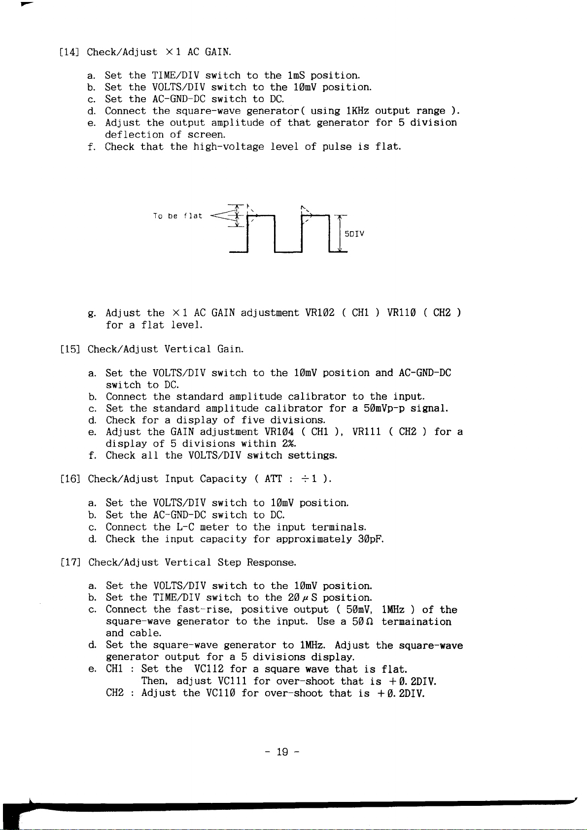
Check,/Adjust
t14l
x1
AC
GAIN.
a. Set
b. Set
c. Set
d. Connect
e.
f. Check
g.
Check,/Adjust
t15l
the
TIME,/DIV switch to the
the
V0LTS,/DIV
the
AC-GND-DC switch to DC.
square-wave
the
Adjust the
deflection of screen.
that the high-voltage level of
Adjust
for a flat
output anplitude
To
be
the x 1 AC
level.
Vertical
switch to the 10mV
flat
GAIN
Gain.
1nS
generator(
of that
J II
adjustnent VRIA2
position.
position.
using lKHz
generator
pulse
is
LJ-
(
CH1
output
for 5 division
fIat.
)
range
VR110 ( CHZ
).
)
a.
b. Connect
c.
d. Check
e. Adjust the GAIN
f. Check
Check,zAdjust
i16l
a.
b.
c. Connect
d. Check
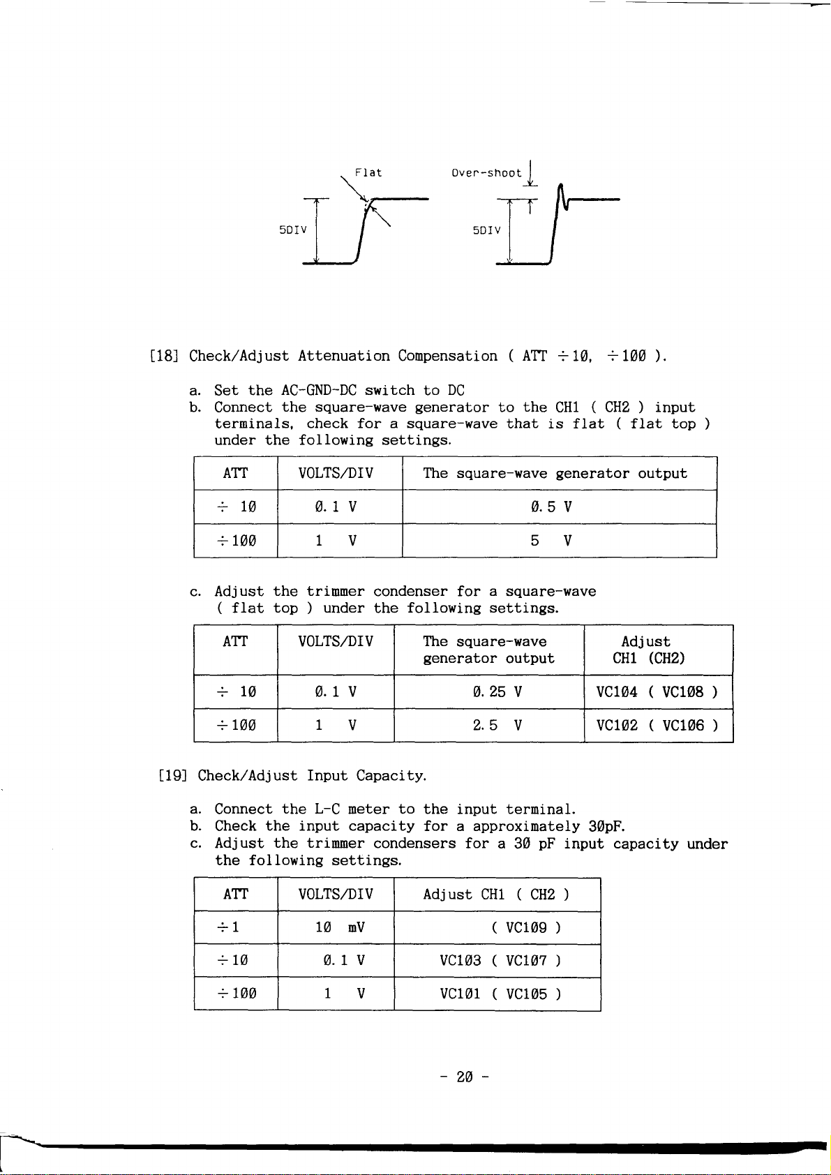
Check,zAdjust Vertical Step
ll7l
a.
b. Set
c. Connect the fast-rise,
d.
e.
the
Set
switch
Set
display
Set
Set
Set
square-wave
and cable.
Set
generator
CH1 : Set
CH2
VOLTS,/DIV
to DC.
the standard
the
standard
for a di.splay of five divisions.
of 5
aII the
Input
the
VOLTS,/DIV
the AC-GND-DC switch to DC.
the L-C meter to the input terninals.
the input capacity
the
VOLTS/DIV
the
TIME,/DIV switch to
generator
the square-wave
output for a
the
Then, adjust
: Adjust
switch to
amplitude
amplitude calibrator for a
adjustnent
divisions wiLhin 2%.
VOLTS,/DIV
Capacity
switch to 10mV
switch to the 10mV
to
generator
YCLLZ
the
for
VC1ll
VCILA for
the 10nV
calibrator to
VR104 ( CHl
switch
(
for approxinately 30pF.
Response.
positive
the input.
divisions
5
a square wave
for over-shoot
settings.
ATT : =1
position.
the
over-shoot
pS
20
output
to lMHz. Adjust
position
),
).
position.
position.
(
a
Use
display.
that
that
that
and AC-GND-DC
the input.
50nVp-p
VR11l ( CHZ
50mV, lMHz ) of the
5AQ
the square-wave
is flat.
is +A.?,DIV.
is
+A.ZDIV.
signal.
)
ternaination
for a
-19-
Check/Adjust
t18l
Attenuation
Conpensation
(
ATT
+10,
+LgA
).
a.
Set
b.
Connect
terminals,
under the following settings.
ATT
+10 9.1 v 4.5
+ IAA 1V 5V
c. Adjust
(
ATT VOLTS,/DIV
+la 0.r v
+
Check,zAdjust
t19l
AC-GND-DC switch
the
the square-Hrave
check for a square-wave
VOLTS,/DIV
the
trimmer
top
flat
Lgg 1V
under
)
Input
to
generator
The square-wave
condenser for
following
the
The
generator
Capacity.
DC
the
to
that is fLat ( tlat top
CH1 ( CHz
generator
v
a
square-wave
settings.
square-wave
output
a.25 U ucra0
2.5
V vcr02
)
output
Adj ust
cHl
input
rcHz)
(
vc108
(
vc106
)
)
)
a,
Connect
b.
Check
c,
Adjust
the following settings.
ATT
the
L-C meter to the
the input capacity
the triruner
VOLTS,/DIV
+1 lA
+L0
0.t
+ lDb 1V
condensers
mV
v
for a
CH1
(
(
(
terninal.
pF
30
(
CHZ
vc109
vcr07
vc105
)
)
)
input capacity
)
input
for a approxinately
Adjust
vc103
vc101
-24-
30pF.
under
TRIGGERING
SYSTEM
Check,zAdj
tZgJ
a. Set
ust TRIG CENT.
TRIG
the
pull position,
switch to the
b.
Connect
a
0.3DIV ( SAKHz
c. Set the
d. Adjust
the sine-wave
TRIG LEVEL knob to the nidposition.
the
waveforn,
e. Next,
set the TRIG
that synchronization is effected. Aft,er confirnation, Ieave
the TRIG-SLOPE
out.
Check,zAdjust
tzt)
a. Set the VOLTS,/DIV
switch
switch to
knob to
b. Connect
CHz) for
Adjust CH2
c.
Next, adjust
d.
to
the
the sine wave
SOURCE switch to the
the
V0LTS,/DIV switch to 10mV and
pS.
20
generator
).
VR105
0.3DIV
so that synchronizaLton is
on
the
screen.
SLOPE
in the depressed
Trigger Balance
switch to
10uS,
VERT,
a five division
the
the
nid-position.
position
VR113
so
TRIGGER
V-M0DE swj.tch
generator
cntrol so
that
-
to
50mV
SOURCE
$1KHz)
both
the TRIG SLOPE
CH1,
to
the input connector for
effected on
(
push
state.
to the input
that
waveforns(CH1 and
: inner
state ) and insure
Readjust when
(CH1
and
CHD,
switch to INT, the INT
to
DUAL, and CH1
connectors
waveforn comes to
CH2
the
TIME,zDIV
the
TIME,zDIV
position
CH2)
knob
the
stepped
TRIG
(CH1
CH1.
coincides.
and
X-Y
l22l
122-l
122-21
Operati.on
Check,zAdjust
a. Set the V-MODE
[X-Y],
of
CHZ
b. Set the VOLTS,/DIV switch to
c. Connect the standard anplitude calibrator
connector.
d. Set the standard amplitude
e.
Check
f. Adjust the
within
Check,/Adjust X Position
a. Set the TIME,/DIV
the
the
b.
Check
i.s within
c. Adjust the
graticule
for a
horizontal POSITI0N
AC-GND-DC switch
to see
X Gain.
switch to
the AC-GND-DC switch
to
GND.
display
X
3%.
0.2
X
center.
adjustnent
GAIN
switch to the
that round spot
division
adjustnent
CENT
CH1, the TIME,TDIV
divisions.
of 5
Center.
control to
to GND.
against the
of CH1
the
calibrator for
to DC,
10nV. with X
VR108
is near
VR10? to
for a displ.ay
[X-Y],
the nidposition
the center
horizontal line.
switch
the
1 GAIN.
to the
a
50mV.
the
V-MODE switch
position
to
the
AC-GM-DC
CH1 input
of
graticule
spot
divisions
5
and
at
switch
to
the
CHl.
and
-2r-

122-31 Check,zAdjust
a.
Set
the
AC-GND-DC
b.
c.
d'
e'
1231
Check,zAdjust
a.
connect
b'
check
c'
Next,
d'
check
connect
inputs
Adjust
8 division
Center
CH2
Check
line
the
through
the
the
P0SITI0N
the
of
0.4
the
for
connect
for
phasing.
X-y
switch
constant
50o
constant
horizontal
display
controts.
CRT display
division
CAI-IBRA:rOR
pROBE
the
the
ADJUST
pROBE
ADJUST
PROBE
the
PROBE
PRoBE
of
amplitude
cable
anplitude
vertically
or
ADJUST
ADJUST
and
displ
for
ay
an
less.
terninal
ternination
frequency
ADJUST
output
CH1 and
signal
50o
signal
ot
EAKIIi.
and
horizontally
opening
(
0.SVp_p,
ternination
of
CH2
to
DC.
generator
t.rnination.
generator
at
the
horizontal
LKHz
to
the
Digital
of
Lwtz,
to
a.25V,
within
to
for
with
).
*itttn
the
cHl and
an
the
CHl
center
Frequency
zg*tagauz
Digital
tgxra.zzs
cH2
and
counter.
-
r\aaHd.
Multineter.
-
0.275v.
I
I'
l-
r
I
-
/"
F
f-
lb.
I
r-
16.
[-
I'
F
t-
l.
P
-22-

-
Description Mininum
1, Constant Anplitude
Signal
Generator
SAKHz
naxinun frequency
variable amplitude
2. Standard Amplitude
ibrator
CaI
Anplitude accuracy
variable
4AY ; frequency
wave
-
Square
3.
Generator
wave
Variable
llilHz ; output
10nV to 100V
[, Digital Multineter
Digital Frequency
5.
a.
G
w. l% accuracy
Counter
TEST
Specification Exanple of
reference
anplitude
frequency
I% accuracy
Table
EQUIPITTENT
frequency
56llHz
:
4.25%
SnV to
;
: lKHz square
: ltHz to
anplitude
(tr=<3nS)
5-1.
REQUIRED
,
:
Usage
Check
and
horizontal,
trigger
bandwidth.
Check horizontal
Vertical
Check
gain.
probe
and vertical
conpensation.
Check
Check
power
PR0BE ADJUST
supply.
vertical
and
frequency.
Mark
Tine
i.
?.
CabLe Impedance
Generator a,
L% accuracy
RG-58,/U ; length : 42 inches
connectors : BNC.
Ternination
8.
Attenuator
l.
Inpedance
Connectors
Ratio:tAX;connectors
BNC;impedance:50O
-
T
M.
Connector
Connectors : BNC.
:
:
:
50O
50
BNC.
Check horizontal tining.
:
type
;
O
External trigger operation
check. Horizontal
adjustnent.
and
Vertical Anplifier
gain
check
conpensation
checks and adjustnent.
Vertical
bandwidth
External
Anpli.fier
check.
trigger operation
checks.

6. SEMTCONDUCTOR LEAD
CONFIGURATI
ON
MARKINC FOR TRANSISIOR
rYPE
2SC3775
"lM8T3906
.4M8T3904
MARK
TYPE
TRANS
OF
1
2SA
206
KSC 1
674
2SC290
2Sr(304E
2SC | 907
KSC 1 730
2SA 1 029
2SC3779
FOR TRANS
ING
IRANSISIOR
OF
KTA968A
2SD362R
KSD288Y
KSAI381
KSC3503
ISIOR
I
KTC3875
KTA1504
ELECTRODE
ISTOR ELECTRODE
ELECTRODE
t/'
LECTRODE
E
123
rooo)
r
e3
3
2
(TOP
V
EW)
I
MARK
NG
I
l.EMITIER
BASE
2.
3. COLLECTOR
SO URC
E
GATE
2
\)
DRAiN
I,EMiTTER
2. COLLECTOR
3. BASE
1
.8ASE
2.EMITTER
3. COLLECTOR
COLLECTOR
c
BASE
EMIITER
3
(FRONT
MARK I NG
1
BASE
.
COLLECIOR
2"
J. EM I
1
EI..lITIER
2
COLLECIOR
3
BASE
V
3
2
1
TTER
a
IEW)
1
MARK
TYPE OF
RL105
1 N4005 AG0 1 A
1SSr33
ESJA52DZ_s.
DZ-6.88
DZ-7
DZ-8,2B
DZ- | 28
DZ.??B
MARK
TYPE
GL79r
GL
CL
74LS 122N
7 4LS7 4AP
74LS 14
74[S02
74LS |
74LS00
LF356J
MC4558CN
FOR
ING
DIODE ELECIRODE
MA185
I
2
1B
5B
"
FOR
ING
OF
IC
2
7805
7
81?
0
IODE
D
ELECTRODE
MARK
INO
-rL_t-
-{r-F
--il- -K-
ICS
PACKAGE
' i-
I,^I
tt \t |-
l\rll--P.
lvl r
Lj..-]||5
fr3
I /\l
| | \t
| \ )t
t-l
OUTL
@
ffi
POLAR I TY
--kc-
INE
?
1
C0MM0N
.
NPUT
2. I
3.
OUTPUT
2
l.INPUT
2. C0MM0N
S. OUIPUT
I
9i
LA

(9
18
{
(r'
@
@
@
|
7
ELECTRICAL PARTS
"
|
leE=
le=-
ARRANGEMENT
ll
WITH
ADJUSTMENT
LOCATIONS
@
|
lryrtr
(]
a
0:"€*&F3
s,.
:€
)i
ri(
}
irri
'
\,,J1.i
=,,
fr
, , *iR'(rri
i;3i
i.--rl iiIil
i i
gtt-[
,,,,
Fq,, i ^*,[I{,i
l'==TIIFd
i il I
iil
-.;,J--ll..o
For
lrr{
I
j----1.,;p
l!q"qJi7
I
jn^"""^
!"
:
;
r;Ei iriill*i
i^rl
cL
ri
,,)l,-ei
-:,,F"..-]
,'
ilr
*'.:u
'
rcroe
rr
llll)::
i
,
.',, tr#-
-
.\=
Llfi;=t;.,\,,J
Il |
:,,,,1=
''T,
1
r
,
l ll
;rL--u[J
-
if
ffi-E,jf
rrf ..O
Y--
6-1T,
l*ofiill
6;'
,,*
'
,,*
;l
ii
3
ffi
pr
r-Eifr
,,s-+,1!; .,€: ^
I
f-fi
:i{i.j
'u'i
.'E"f.)*;
in11it/-----,i--
I
|':vv:
:0|];
xH:
#'*j=,ko-
'
-',,,*R:,i,
-OF
-- +g[
;*,
l€r:l
i€
18,??
:
+=(=1F,,,,""':.,".Jf',=',,
9
rr
'
':-
,J
)
r'?'l
,t:-)g
--]C:
--s
[:i,,,F9,:s_*
(!.
u,'o
u,,,
,',0
,",,
]gl
,'i
:r- r
.X :';ilF-
-.|flr*l
C
5 | 3J505.
E!tt']/
*/0,-
Poo
crr
-{-l
,$
lll+Dtrocr50
l\-
r
:
1
::\lo''c$5:.
l
0=
i
,
i
t.
*E"$$:';13 -sr
r
*-f ): I lh
-L
n"nl ll I t li
t-
----
F
'
il"
",,1"'H
:
lejl IJ'i
"
;r
.;
rr
:
O
'|
'"1
r"
j
_dt6l
, , .
i
;
D5iv
...ffi-
l -r'rt
J.e ir's
,l
*
"
l; l'6$rl I-r
l.)1
1 ili
--X
+
]&i
:-
i-nA*t
L
I" a
0s'80?0P
| + Dtos
J
"
t.
rtor
. I ll,ro
,f_l
imiol
:
,.1
,'Y
,,,,.
\..
(.
D'tt
Dtt'
'-ffi-
8""
??uE-:l-
r;
trr
[lJ
?rr?
i
-
rM;tL
trrrr!llllll-
r
+
olL:,_
\.J
1-t
-
-e..,
*-v8]i-rr"r
gfl
;ll
Yl
UYIIE
r;
..-e
..
':g
:
:
,j
)
u,o!
-
-
t il;
rr6_.int
--
! /
'
0r52
i=-
|,-
I-JL-J
,'
J
,
r-r
.
u +l
+
*
rw
Drlr
| 1
<:-
\
*R--
irrT
l-
-H-
+
I
I
A3 vcrri
Y-l= 11
Y;
|;Y--'l..,,".:[
--I
I ll--
:l
ll
'l
ll
| ll
.-j_.1-xr
-
;ll
J
n l 19 l l'
crsr
.
|-"1 )
,,.,
L!o-!U-J
-\a -\
ll |
D$?
^+lD!rt
''i'(1
crrr
I
lAgA +
;
I 0:0:0
Leo
,'r
?:)
rH
,;i6'l
3l
il
(-.)c'r.
--l | | |
{
14
. r i-i:F
'HlHr
l';i';fid^-mi-
---+ \^/
:nl1J
r
F*]{P
,,'
I--A
Hl
al :l I I ll ll
cr 50
-Al \
/)
9|\-V
'Uv'
\y
CJ a ll;m
vA.
:l ].J,,,,e]{
-v
(
i
l-,'-
J?^
I l o2oo
r ro2oo
u;u
f:l
I
rE Fl il-t-"
l'I
l' 4
r nrs?
Jrrsr
FF
--F-i
"
{ )
\GtJ,,,,
lGtlcr.'
r--r----r--lcci5
llllllrflr
I I I I lvv'
!-rJ#; i
l-1: l-1
sl
.:l lf----1
6l
(
Ycll2
.-
,,..
f
di
cEI
fNrel
Ll
-----1rr
,,s,
trsl
I
proil
prffi-vrilL-
-
rL:J
(-...........';
i
Q
ot?! - or?t
or?a or?t ( |
| | |
I I I
I I I
-i{-,
"nnffi
:ftl]ililg
ffi?
lr_
|
-
r+! r'
5
-oi'
-
.O
|
;
t.i..
i
.,
:
t'
;;r_-lQ[:]
l?-
MAIN
BD
lr
15
n
LJll;
c-
ct
\/
c's
SILI((COM SIDE)
/
n
ct
:l
V rrB
<=>
t?
..".G
+
Dt3l
o
I
I
(i;
\
/l
trs
01a0
{T-D
ct15
\!--l
:
t/-\
t,3
v
+
-+
-:uae
5
+
il
_D'l?l ll
--ur
I ll
-ur.
l lla
\t lt
\t tl
'lJg
01J5
,/
#ol,
-€ii*
+
a<Y_-;
I
ll l:
(-
I
t-t-l
ilI
ll lr
ll l;
II
ill
,0,
Dtz!
Dr2?
0r$
DTJ6
B
ctt6
-
3
c
lli
3
{1-r\
r'\
/c(
(i'
Ir-l'
()'
o
(3\
t6
\7
SCI.
r
MAiN
BOARD

Pa80 I
'F_-l
-<-
\a
\ .>
a )'
\L/
lr-{
tt
n-{--J
|
vn90
ll
l@
/ ,6
v
/T\l
f
ivfI
q-n-n.T
cHl
ls
xr
I----ll
v vl
,'l
3
CL
r";;l
400v
I
|
R80?
P06trI0N
680r tt
CONIROL BD
"
I
I
I
I
*\f--
3f-l
3l
I tt lv
ll-
rr
)c
I
PBgo3
azsx
I
I laoov I O".
I
ll---_l"eaoo
I
a
s
dl
3h=
n
vli
tNv
|
;il";',a-
(COMP"
F /T\
ll
ffin
rnro
rR
hOOE
IG
SaO4
cc
|
SiLK)
{i--l
u".0.
rl
\17
i
rever
f.tlf
t
oeeosll
6903
O".
PA806
vRoos
H PO6ITION
6805
CC C
xl
I
U
t)
C
#r
tr(1TJ
tl
R80 |
-o-
:q
-eeoor---C)-
XrO
!
q-H-H-p
-O-
c^LC
qtt-qA^
.0",t":P.r..?:o*o
5
SELECT
re84,
PBgOA
---L
I
3-567
BOARO
3.12
RSoJ
Rooa
tls
C
SC8,9; CONTROL
Dranr
1x'.P,
r--l
Y- Y+r
I
& SELECI BOARD
-^ -^
cRr
s
.,_!f*,W.
7
\
\
5() \ Qo'
=P,Ns3s-0,)t'H,
lvre
REo(
t----/
)
U) U
GRY
rr
(VHI) N (GRY)
-.0'-
"
K-?OM
Hr-
(
n
(:3X
;
GRN
j"Eo
SC I 3.
CRT SOCKEI BOARD
26

A.
EI-ECTRI
CAI- PARTS
I-I ST
;l
1l
\l
fl
pl
r.0r
I
rco.
I
rl0s
I
--r
I
9l
-:l
!
;l
rDl
,t?l
_J
(1).
N0.
FND NO
1
c3g2
3
c3g4
c355
7
c357
I
c90i
11
c903
13
Pt02
R106
t7
R108
19
R118
2L
I
RLzg
23
R303
%
R305
27
R307
n
R309
31
R311
ec
R475
?R
R477
37
R4?9
39
R481
4T
R483
43
s102
45
swz
47
uclM
49
uc104
vc106
51
vc108
53
ATTENUATORS
DESCRIPTION & SPEC.
CAP SMD,
Sl,tD
CAP
SMD,
CAP
Sl'|D,sOV, J, 47PFQOI2)
CAP
CAP
Etg
cAP
C0NNECTOR V llFW., LV-9649-92
It|. F,L/AV,0.5%,WK
RES
lll. F,
RES
M. F,I/4V,9.5%,WK
RES
F,
RES [|.
SMD,
RES
SMD,
RES
SMD, s. tV, t%, 82Q912)
RES
SMD,
RES
RES SMD,
SMD,
RES
SMD,
RES
RES SMD,
SMD,
RES
USED
NOT
st RoTARY, ADR255S, 8773-ttg2
sH stIDE, SSSUoz3NC CHzCoU
CAP TRIMMER, TZOSNIOOFR,
TRIMMER,
CAP
CAP TRIM}IER, TZO3NIOOFR, IHT
TRIMMER,
CAP
2zgPFQgTz)
J,
5OV,
J,47PFQ0I2)
sgY,
J, Z^OPFQDTZ)
5Ol{,
[|,4?UF(SMS)
16V,
g.
4y.,
L/
L/AV,
g.
LV, 5%, TOQIIZ)
0. !t, 5X, 1gQg12)
g.
tU, 5r(, 27
g.
LY, 57,, L'(NN)
g.
Lv, 516 L,Qgtz)
O. IVI, 52, IOQALZ)
g.
LVt,
b. LII,
TI1K
5%,
g.
5X, 777K
Qgt2)
22QgL2)
5%,
T%,
LSOQLIZ)
THT
TZOSNIOOFR,
TZO3NIOOFR,
UHT
WHT
P/N
CKIHIzzIJ
cK7H1470J
q\HI221J
CKIHT4TgJ
cl12GL473K
CE1CR476M
537-Mt-1
Rl,|BP99O3D
RMBP1113D
RMBP99O3D
RMBP1113D
Rl|OI1OROJ
RI|OI1OROJ
R[{OI82ROF
RVAI?TROJ
Rl'|OI15ROJ
Rl'tOI15ROJ
RMOI1OROJ
RM0IZaROJ
RMOI1SOOF
NOT
522-02vt
52L-trz
581-133-1
581-133-1
581-133-1
581-133-1
N0.FND NO DESCRIPTION & SPEC.
2
4
6
8
1g
L2
T4
16
18
20
t2
24
26
?,8
30
32
34
36
38
40
42
M
46
48
5g
52
c303
c305
c356
c358
M2
PIOL
R105
RIOT
Ri17
R119
R302
R304
R306
R308
R310
R4'.14
R476
R478
R480
R482
s101
s901
vc101
vc103
vc105
ucI07
Sl'tD,
CAP
NOT USTD
CAP SMD,
NO( USED
CAP t||.
C0NNECT0R
RES M. F, l/At,
RES M. F, L/AV,0.5%,WK
It|.
RES
I'l.
RES
RES
SMD,
RES SMD,
NOT
USED
RES SMD, 0. LV, tt6 \ffi(mz)
RES Sll|D,
RES
SMD,0.lU,W6nQ0p)
RES S[fD, 0. w,
RES St{D, 0. lV,
RES SMD,
RES SII|D
slf R0TARY, ADR255S,
st st
IDE, sssuo23Nc
CAP
TRIII|II|ER,
CAP
TRIII{I'|ER,
CAP
TRIMilER,
CAP
TRI}|iIER,
J,
W,
nAPFQgtz)
J,Z7^PFQOIZ)
ffiV,
AMV,K,O.O TUF
F,
|AFER,
Uf-064&{5
0.
lg. IK
57q
F, t/AV,0.5Z,Lg.LK
F,\/4Y,9.5%"WK
g.
\U,
nQ0l2)
5%,
g.
LY,
IOQqIZ)
5L
g.
tY,
g.
tU,
g.LV,
grl2)
n
5%,
(nIz)
n
52,
Lgztlz)
5t,
LgQgIz)
57,,
t6EZQLLZ)
8773-7792
cHlcou
TZO3NIOOFR, IHT
TZOSNIOOFR,
TZO3NIOOFR, UHT
TZO3NIOOFR, THT
fiff
;
PAGE
CKIHIZilJ
N0[
CK1HI?/lJ
NOT
1
P/N
awA73K
531{18-7
RMPUUD
RilBPgoMD
RitsP1012D
RrtsP9003D
RWT2a.0J
RTOIIgRzu
NOT
Ri|OI$EPF
RWTZTWJ
RIMIZIWJ
RWTZTWJ;J
Rli|OIlOIRzu
RIIOIURAI
RlCII8zROF
snqb[
521-tn
581-133-1
5E1-133-1
581-133-1
581-133-1
27

(2>.
CH1 INPUT AMP.
PAGE ; 2
N0.FND
ctgT
1
3
cr03
u05
5
7
c\n
I
c308
c310
l_1
13
DTOI
15
D103
LI
0101
19
8103
2L
R103
R109
23
25
R111
27
R113
29
R115
31
R313
33
R315
35
R317
37
R319
39
R321
4I
R322
43
R324
45
R338
R344
47
49
s801
vR101
51
NO
DESCRIPTION
CAP CER,5W\,C,1PF(T. C BLACK)
CAP EtE, 16V, M,
CAP EtE, 16V, I|,
SMD,
cAP
cAP SMD,50V, K,
cAP
Dr0DE. 1SS133
DIODE
FET,2SK3O4-E
TRANSISTOR,
RES
RES
RES
RES M. F,t/4i/'0.5%,ffio
RES M. F,I/411,9.5%,68
RES SMD, 0. fi|, I%, 75OQOI2)
RES SMD, 0. IY, 5x, tgQgLz)
RES SMD, 0. LY, 5x, 4. TKQLIZ)
RES SMD,
RES SMD,
RES
RES SMD,
RES SMD, 9. fii 116
RES
SH
RES SR,
ffiV,C,5PFQ712)
SMD,
50V,
ZENER,DZ-7.58
ll. F,l/4U,9.5%,ffiuK
M. F,L/Av/,9.5%,ffiK
M. F,I/Ay,0.5%,3K
g.L]f,,
g.IU,
SMD,
Iv, M,
A.
Iy, T'6
O,
SMD,
9.fit,57,, tgQgtz)
SLIDE SSSUOZ2NBO11 x5
VGO68TL1B-2OKB
& SPEC. P/N
47UF(SMS)
47UF(SMS)
\WgPFQUtz)
K, o.gtuFQgt2)
KSC1674-Y
fl,4.7KQ912)
tX,
43gQgI2)
430Q0t2)
TZKQOTZ)
3. 3KQ0l2)
N0.
CIZHRaT0r,
cE1CR476M
CE1CR476M
CKlHIO5OC
CK1HI1O2K
CK1HI1O3K
585-t20
585-075
6TI_I4O
611-130-1
RMBPsOO3D
R[/IBP6OO2D
RMBP3OOlD
RMBP68OOD
RMBP68ROD
RMOITSOOF
R[|OI1OROJ
RMaT47OlJ
RMaTATgTF
RMgT43ggF
RM?I43ggF
RMgITZZZF
R[{OI33O1F
RMOI1OROJ
52t-tlr
572-324-l
2
4
o
8
TO
72
74
16
18
n
22
24
26
28
30
32
34
36
38
4g
42
44
46
48
5g
52
FND NO
c7g2
c7g4
c306
c3g7A
c309
c313
Dtgz
PP101
ar02
alg4
RLg4
R110
R112
R114
R312
R314
R316
R318
R32g
R3214
R323
R337
R339
RA101
u101
YRIgz
DESCRIPTION &
CAP CER, SWY,K,IWPF
CAP EtE 16V, M,4?UF(SMS)
CAP SMD,
SMD
CAP
CAP SMD,
CAP SMD,
DrODE, 1SS133
CONNEC"IOR
TRANSISTOR, KSC1674_Y
TRANSISTOR, 2SAIO29-D
RES I'|. F, l/Alt,g.5Z,5WK
RES M. F, T/AY,9.5%,LzK
RES ltl. G,L/211,5X,16It|
RES M. F,l/Ay',LX.820
RES SMD, O. Iw,
RES SMD,
RES SMD, A. ty,
RES SMD, 0. r[, fi(, 3.
RES SItlD, A. tV, t%,
RES SMD, 9.1Y,l%, 4.WKQL12)
RES SMD,
RES SMD,
RES SMD, O.
RES
ARRAY. RA-OSC-V
IC
OP
RES SR,
J,
5g\,
ffiV, J,LZPFQOIZ)
J,IMPFQtIZ)
sgY,
J,
sAY,
HOUSING,
rr, rX,
0.
g.
Iyt,
g.
1II,
TII,
AMP, LF356J
Y0/f8TLLB_AMB
SPEC. P/N
TSPF(29L2)
tggPF
QOIZ)
CS25g-95
22KQOT2)
52,
ffi(2012)
2.
5%,
2KQ0L2)
9K(nL2)
t20Q0t2)
\KQ,LZ)
5X,
IX, IOKQOIZ)
IgQgLz)
5%,
cKamnx
cE1CR476[l
CK1HI$AJ
CKIHITn.]
cK1Hr101Jl
I
cK1Hr101Jl
585-Ln
$1-4m
I
I
611-130-1
611-133
RrtsP5003D
RIEPLWaD
RG0C?1661
R[tsP8UoF
RIIfiTWZJ
RTCII68ROF
Rwrmu
R[0r3901F
RVATIWF
Rt0I4991F
RIIfrTTWLJ
ilMTIWN
Rl'0I10Rft1
591-325
59t-ga
572-3It7
28

7_
I;2
;r
l|0.FND NO
I
m---l
rm4?srl
tHr150Jl
HrmJl
rHr101J
I
tHr101J
I
rr2u
l
t-M
I
L-130-11
r-133
|
|P5003D
I
Purnl
xP16&rl
WMI
trwzrl
'r68R0Fl
nmrrl
'rs01Fl
'tIlWFl
'r4ee1Fl
trrffilrl
trrffizFl
'r10R0J
I
,-w
I
:AA
I
)-316-11
(3).
1
c108
3
utT
c350
5
I
C3514
I
c353
ii
DTO4
13
D106
15
Q106
t7
Q108
10
R121
2l
R123
23
R125
25
R327
n
R459
n
R461
a1
R463
ea
R465
Jb
R467
37
R4684
39
R47g
4l
R472
43
R/.tn
vc109
45
vR110
47
CHz INPUT AMP.
DESCRIPTION & SPEC.
cAP ErE" 16V, I|,4?UF(SMS)
CAP EtE 16V, M,4?UF(SMS)
SMD,
CAP
CAP SMD,
CAP SMD,sOV, J, IMPFQOLZ)
DIODE, 1SS133
DIODE, 1SS133
TRANSISTOR. KSC1674-Y
TRANSISTOR, 23AIa29_D
RES [|. F,I/AV,0.5%,WK
RES It|. F,t/AV,4.5%,3t1
RES It|. F, I/4V,
RES SMD,
RES SMD,
RES SMD, 0. wt, U, tgKQgLz)
SMD,
RES
RES SMD, 0. LY,
RES S}|D, 0. 7Y, 7%, 12K{29I2)
Sl'|D,
RES
RES Sl'lD, 0. 7V,
RES SMD, 0. LVt,
RES ARRAY, RA-OSC-V
CAP TR IMMER, TZOSZAT
RES SR,
K, TWPFQOI2)
5gU,
C,
5OY,
5PFQO12)
g.
12K
5r(,
g.lH,'x,
g.
0. 7v, 5%,
g.
UG0fETLIB_^MB
tgQgLz)
7V,
1gQ0I2)
5%,
4. 7KQ0L2)
22KQ0l2)
526
7V,
I5KQ0L2)
5%,
7%, 430QgL2)
7t(, ffiQgtz)
OFR, BLU
P/N
cE1Ct476M
cE1Ct476M
CK1HI1O2K
CKlHIOSOC
CK1HI1O1J
ffi\-r2g
585-720
611-130-1
611-133
R[{BP5OO3D
R[{BP3OOlD
RMBPT2g2D
R}|OI1OROJ
RMOI1OROJ
RMaIIOOZF
RMgrATglJ
RMtIZ^OZJ
RIIOILaaaF
RMgIIffizJ
RMgrASA0F
RMOI6SROF
591-325
581-145-1
572-3t6-1
N0.FND NO DESCRiPTION & SPEC.
2
4
6
8
Ig
t2
t4
16
18
20
22
24
26
28
30
32
34
36
38
40
42
44
46
c109
c111
c351
c352
c354
Dt05
8105
Ql07
R116
RTZZ
RT24
R126
R449
R460
R462
R464
R466
R468
R469
R471
R473
ULgz
vR109
CAP ELB
CAP
CAP SMD, 5gY, D, 7PF
CAP
CAP
DIODE ZENM,DZ-1.58
FET,2SK3O4-E
TRANSISTOR, KSC16?4-Y
RES [l. G, 7/2V,5r6t6tt
RES l'l.
RES
RES It|. F, T/AY,9.5%,W
RES
RES SMD,
RES SMD, 0. lY,
RES SMD,
RES SMD,
RES SMD,
RES SMD, A. tV,
RES SMD,
RES SMD,
IC
RES SR, VGO68TI1B-2OKB
16V,
trl,47UF(SMS)
CER,
WU,K,LWPF
SMD,
5OV, K, O. ANF
F,
I/Av,g.516WK
[|. F, L/AV,t6829
g.
S}|D,
LV,
IOQuIZ)
$6
g.
w, t%, 3. 3KQ012)
2.
516
g.IY,
T'6 LzgQgTz)
g.
lV, lt6 4. 1K(29t2)
g.
LV,lX, 430Q0L2)
Lr6 3.
g.
lY,
tKzgtz)
526
g.
IV, I%, 750Q972)
A[{P, tF356J
OP
QgLz)
QOTZ)
2KQ0t2)
qK(AJLz)
PAGE ; 3
P/N
cElCItT$l
cYa&1gx
c/i.THTNW
CK1HI1O3K
XIHTWJ
wt5
6LL_IM
611-13G-1
RG0CP166l
RItsP5003D
Rt'lBP8nm
RI|BPGSOOD
RIIOI1ORAI
Rl'CII3301F
RWTMLJ
RYAILWF
RUAIATgLF
RWT&3/r/F
Rl'OI39O1F
RVATIWLJ
RWITWF
59tn4
57z-gZ+-L
29

(4>.
CHl- PREAMP.
& TRIGGER
PICK_OFF
;
PAGE
4
N0.
3
7
I
11
13
77
19
2I
23
25
27
29
31
33
Q<
37
39
4t
43
45
47
49
51
53
55
57
FND
1
c106
c311
c314
c316
c318
C32L
c323
D107
4303
Q305
Q30',1
8309
R326
R329
R331
R333
R335
R34g
R342
R345
R34?
R350
R352
R354
R356
R359
R361
R363
vR104
NO
DESCRIPTION & SPEC.
CAP EtE, 16V, [|,47UF(SMS)
cAP
S}|D, sAV, K, 0.
cAP
SMD, 50V, J, 82PF(29r2)
CAP
SMD,
5OV,
cAP
SMD,50V, K,
CAP SMD, 1gY, K, O, OIUF
CAP SMD,
DIODE ZENER,DZ_1.58
TRANSISTOR Sil|D
TRANSISTOR
TRANSISTOR SMD, MMBT39O4-1A
TRANSiSTOR
RES SMD,
RES SMD,
RES SMD, 9.7Y,5%,
RES SMD, 9. 7Y, 7%, 82Q0I2)
RES SMD, A.
RES SMD, 0.flt,516
RES SMD,
RES SMD, fr. tV,
RES
RES SII|D 0. Ilf,
RES SMD 0. 7v,
RES SMD, 0. 7Y,
RES SMD, 0. !t, t%"
RES Sl'lD, O. LY,
RES SII|D, 0. tw, t%,
NOT USED
RES SR, VGO68TI1B_1OOB
sOY,
g.
g.
g.
SMD,
b,
gtUF
Qgtz)
J, 6EPF(2OI2)
g.btuFQglz)
(2912)
J,27PFQA12)
2SC3775_OY3
SMD, KTC3875-Y
SMD. I{I{8T3906-2A
IV, t%, 33gQgt2)
7V, 1r(,
ffigQg|z)
L.8KQO12)
Tr, 5%, 4.
IV,
Ili/,,
7KQOIZ)
4.7KQgt2)
5%, lgKQOIz)
22KQ0L2)
5%,
5%, TKQOIZ)
52(, 270KQA12)
5%, 1WQ0t2)
5%, 47
Q012)
82QAl2)
52, TKQglz)
r. 5K(29t2)
P/N
N0.
cE1Ct476M
CK1HI1O3K
CK1HI82OJ
CKlHI68OJ
CK1HI1O3K
CK1HI1O3K
CKIHI?7gJ
fi5-b75
orlrcco
611-679
611-654
611-653
RMOI33OOF
RMOI68OOF
Rl}{OI18O1J
R}{OIS2ROF
RM?T47glJ
RM?IATOTJ
RMOIIAZ?J
RMOIZZZZJ
Rl'lOIlOOlJ
RMqTZ7g3J
RMOIIMOJ
RMaIATROJ
R[{OISzROF
R[|OIlOOlJ
RMOI15O1F
NOT
572-327
Tg
t2
T4
16
18
2g
22
24
26
28
3g
32
34
Jb
38
40
42
44
46
48
5g
52
54
56
58
FND
NO DESCRIPTION & SPEq
2
cr07
c3I2
4
c315
8
c317
c320
$n
c325
Pllg
a3g4
Q306
8308
R325
R328
R330
R332
R334
R336
R341
R343
R346
R348
R351
R353
R355
R358
R360
R362
vR103
vR8g2
cAP
CAP
CAP Si,lD, 5OV, J, 68OPFQTIZ)
NOT USED
cAP SMD,
cAP SMD,
NOT USED
CONNECT0R WAFER,
TRANSiSTOR SMD,
TRANSiSTOR SMD,
TRANSISTOR S|'|D,
RES SMD,
RES SMD,
RES
RES
RES SMD, O.T]t,52,
RES SMD,
RES
RES
RES
RES
RES
RES
RES
RES
RES
RES SMD,
RES SR,
RES VAR, V?7zL-PUSaKS
16V,
ELg
SMD, sgv, J,
5gU, K,
5g\, J, 27PF
g.
lU,
g.
[t, I%, 330QgI2)
SMD, 0. LVt, I7(, 330Q0t2)
SI'|D, 0. 7I#,
1II,
O,
g.
SMD,
Iw,
SMD, O. Ty',
SMD, 0. rllf,,
g.
SMD,
1\,
SMD, A.IV,1'6
SMD,
O. 7V, 17", 2,
g.
SMD,
7l/,
SMD,
0. tl{, LX,
g.
tU,
VGO68TL1B-5OKB
}|,47UF(SI}|S)
18PF
Qg12)
g.
atUF
Qgtz)
(29t2)
tW-0640-03
2SC3775-OY3
MMBT39O4-1A
[|I'|8T3906-2A
lWQ012)
5%,
4.
5X,
7KQqIZ)
TOQuIz)
IX,
8QgT2)
4.
5%,
7KQLLZ)
5X, IMQOTZ)
tAQgLz)
5X,
It, 1. 2K(29t2)
$AQOLZ)
TKQOIZ)
47
5X,
QgIz)
t. 2K(20I2)
5X, tK(2912)
10KB VP1
P/
N
CK1HI18A
cK1HI681,
N0[
cKlHi103l
CKIHINil
N0[
53I-W2rt
611-656
611-654
611-653
RWITW|
RlCII$m
RMo13300
RW14',101,
RilOI1CIR0
RlCII68Rff
1S
21
%
x
n
m
31
QE
Rufrr{?g1,l
I
35
3',1
39
41
43
45
47
49
51
Rusrrml
RlCIrmCIl
Rr0r120xl
RMI$MI
RrCIr68Ml
RWrnuxl
R[CIr47ml
RrCIr12oxl
RlCII100!l
57z-gtul
57I-gh
30

4
(5).
CHz PREAMP.
;l
ilo.FND NO DESCRIPTION & SPEC.
--.J
r76illi
sarl
81Jll
osKli
,r,
2-71
6l
tl
tsl
wrl
MFI
wFl
01Jl
Rarl
R0rFl
01Jl
wrl
MJI
01Fl
WFI
ml
01Fl
wl,
a1F
alJl
r-11
I
I
c346
c348
3
CtsIO
li
c372
I
c4464
I
11
Q311
I
13
Q313
15
Q315
L7
Q317
R44g
19
R4M
2T
R444
?3
R446
n
R448
n
R451
n
R453
31
R455
33
R457
35
w
R557
R561
39
R563
41
43
l(bob
R56?
45
s803
41
vR111
49i
l
li
vR113
cAP SMD,5gV, K, b.gl\FQurz)
CAP SMD,
cAP SMD,50V, K, o.LtUFQgrz)
CAP SMD,
CAP Sl'fD,
TRANSISTOR SMD, MMBT39O6-2A
TRANSISTOR
TRANSISTOR S[{D, l|t{BT39O4-1A
TRANSISTOR SMD. 2SC3775_OY3
RES SMD, 9.
RES SMD,
RES SMD,
RES SMD,
RES SMD,
RES SMD,
RES SMD,
RES StfD,
RES SMD, 0.
RES SMD,
RES SMD,
RES SMD,
RES SMD,
RES SMD,
Sl{
RES SR, VG068TL1B-1008
RES SR,
WV,
sOU,
50V,
SMD, MMBT39O6-2A
N, 5%,
0. I!i,
g.
Ty,
O. NI, 5%, NKQbTZ)
A. Iv, 5%,
g.
IV,
g.
w,
g.
LI/', 5X, I0KQ072)
7V, 5t(,
O. IV, 51(, IMQqTZ)
g.
IUt,
g.
LY, 5X, 4. 7KQg72)
0. t!f,, M, 3.
g.
TII, 5X,
SSSUO22NBO11
SIIDE
VG068TI1B-1OKB
J,27PFQOI2)
g.
K,
OIUF
QOIZ)
g.
K,
0IUF
QbIz)
47
QOTZ)
n, r.
5K(29I2)
L%, I.
1KQuLZ)
4.
7KQ0I2)
tbzgLz)
5)6
t%,
t. 2KQ0t2)
27uKQAL2)
4. TKQgtz)
5r(,
gKQbLz)
TSKQaL?)
INV
& TRIGGER
P/N
CK1HI1O3K
CKIHI?'IgJ
CK1HI1O3K
CK1HI1O3K
CK1HI1O3K
611-653
611-653
611-654
611-656
R[{OI4TROJ
Rlt|OI1501F
R[lOI15O1F
RMOINnZJ
RM'IA7g1.J
RMOI1OROJ
RMOILaaLF
RMoITWU
RM'I?TgN
RMOIT?fp,J
RllgIATgtJ
RM'I47OLJ
RMOI39O1F
RMOI15O2J
52L-TIL
572-327
572-314-L
PICK_OFF
N0.FND NO
c347
2
4
c349
o
c371
8
c373
1g
PTLz
12
Q312
8314
t4
0316
i6
18
0318
2g
R441
R443
22
R445
24
R447
26
?a
R450
R452
3g
32
R454
34
R456
R458
36
38
R560
R562
40
R564
42
44
R566
R568
46
vc110
48
vR112
50
vR803
52
DESCRIPTION &
CAP SMD,
cAP SMD,
CAP Sl'|D,
cAP SMD,
CONNECTOR Y AFER, LYI-ffi404
TRANSISTOR SMD,
TRANSISTOR
TRANSISTOR
TRANSISTOR SMD,
RES SMD,
RES SMD, 0.
RES SMD,
RES Sl'|D
RES SMD, 0.
RES SMD, 0.
RES Si|D, A.
RES S[fD,
RES SMD, 0.
RES SMD,
RES
RES S}|D
RES SMD,
RES SMD, 0.
CAP TRIMMER,
RES SR, VGO68TI1B-5OKB
RES VAR, YAIZL_PUSOKS
5OY, K,
J,
5gY,
5gY, J,
50V, J, 680PFQU12)
SMD, MMBT39O6-2A
SI{D MMBT39O4-1A
g.
Iv,
7l{,
g.
Llf,, 1%" IKQALZ)
O. IV,
!1,
w,
lUt,
g.
7Y, 716
IV,
0. LUt,
SMD, 0. Lv,
g.
LY,
O.LY,I%, TWQOTZ)
IY, t%, \ffi(ntz)
TZ^ST^MFR,
SPEC.
g.
?LUF
QgTz)
27PF(2912)
82PF
QOLZ)
MMBT39O6-2A
2SC3775-OY3
(nIz)
47
5%,
LK(20I2)
7%,
T7", I. ZKQLTZ)
1KQg12)
5%,
4. 1KQLLZ)
5r(,
lKQIrIz)
516
ffiQ912)
lwQqtz)
5t(,
tt2gIz)
5t6
82Q0I2)
5%,
2.
I'("
2KQ012)
PNK
1OKB
PAGE
4
VPz
;
5
P/N
CK1HI1O3K
CKIHINN
CIffI8zu
CK1H168lJ
537ffi-7
611-653
611{53
611-654
611{56
R['OI4TIOJ
RWTLWIF
RWITWTF
RWflnlF
RIMI1MTJ
waI47atJ
RWIIMIJ
Rilor68Rm
RWTTWJ
R}CII1ORAI
R|t|OI8zRAJ
RWIWTF
RYATI5fr/F
RIiCII3300F
5E1-144-1
572-gb7
57L-sh
r--J
31
-

(6).
VERTICAL CONTROL
;
PAGE
6
N0.FND NO
I
a
c319
c326
5
7
c328
c330
I
11
c332
c345
13
15
c374
1n
LI
c3754
D109
19
D111
2l
D113
23
D115
25
27
D117
29
D119
31
D149
33
D151
35
D154
Jt
P113
39
0109
4I
0310
43
an0
45
R197
47
R35?
49
R365
R36?
51
53
R369
R371
R373
57
/c
x.t
59
61
R3'.17
63
R379
65
R381
67
R383
69
R385
7I
R389
73
R391
75
R438
77
R555
79
R558
81
R569
83
R571
85
R573
87
s903
89
utg4
DESCRIPTION & SPEC. P/N
CAP ELE, 16V, It{,
CAP SMD, 50\,
CAP SMD,
CAP
cAP
CAP
CAP
CAP
sOY,
SMD,
sgY,
SMD,
50V,
SMD,
sOY,
SMD,5OV, K,
SMD,
5gU,
?UF(SMS)
g.
K,
aTUF
QOTZ)
J, 68^PFQAT2)
glUF
K,
O.
{2012)
J,220PFQ0I2)
K, O. OTUF
QgTz)
g.OTUFQUIZ)
J, 68PFQ?T2)
CAP EtE, 16V, II/l,4?UF(SI'{S)
DiODE, 1SS133
DIODE. 1SS133
DIODE 1SS133
DIODE, iSS133
DIODE,1SS133
DIODE, 1SS133
1SS133
DIODE.
DIODE. 1SS133
DIODE, 1SS133
CONNESTOR
WAFER.
LW-0640-03
TRANSISTOR, KSC173O-Y
TRANSISTOR SMD, KTC3875_Y
TRANSISTOR SMD, KTC3875-Y
M.F,T/AV,T%,I.2K
RES
RES SMD,
RES SMD,
RES SMD,
RES SMD,
g.
g.Iv,
g.
g.
tW,
tUt,
tw,
7KQ912)
4.
5%,
t%,3wQgtz)
I. 8K(29t2)
5%,
220QAI2)
5%,
RES
g.
SMD,
RES
RES SMD,
RES SMD,
RES
RES SMD,
RES SMD,
RES Sl|D,
RES Sil|D
RES
RES SMD,
RES SMD,
RES SMD,
RES
RES SMD,
7v/', 1%, 2.
g.
7V, t%,
g.
Ll{,
SMD,
O. IW, 7%, 22gKQgI2)
g.
7l{',
0. w, t%, 330Qgt2)
g.
rv/,,
g.
Llil,
SMD, 0.7llt,52(,
g.
Ilii',
g.IV,5%,
g.
Iv/, T%,
SMD, 0. LV,
0. llt,
RES SMD, 0. 7l{,
Slt
SLIDE,
SSSUO23NC
7KQg12)
33gQgI2)
ffi, 82Q0t2)
I^OKQOTZ)
5%,
gzQgl2)
l%,
7KQ0t2)
4.
5%,
4.7KQ912)
4. 1KQTIZ)
5%,
47(J;012)
T. sKQOIz)
1gQA12)
5%,
5%, 4.'.tKQg7z)
47gQg12)
5%,
TRGMD
iC TTL, GDTALSW
N0.FND NO DESCRIPTiON & SPEC.
cE1CL476M
CK1HI1O3K
CK1HI681J
CK1HI1O3K
cK1wt2?,1,I
CK1HI1O3K
CK1HI1O3K
CK1HI68OJ
CE1CL476M
585-tzg
585-729
585-I2g
585-tzg
585-I2g
585-tzg
585-I2g
585-r20
585-129
531-W2-7
611-669
671-670
6tI-679
RMBP1201F
RMAT4TgIJ
RM?ISOWF
RMOI18O1J
RMATZ^WJ
RMAI,3O0p,F
KMgTLIWLT
RMOI33OOF
RMOiS2ROF
2
4
b
8
7g
72
t4
16
18
2g
22
24
26
28
3g
32
34
36
38
4g
42
44
46
48
50
52
54
DO
5d
60
62
64
RMOI1OO3J
RMOI33OOF
R|\{OIS2ROF
RIIaIATgTJ
RMOTATgIJ
RM?IA'IOTJ
RMOI4TROJ
RMOI15O1F
RMOI1OROJ
RMATAIglJ
RMTI TMJ
521-112
66
68
70
72
74
'16
78
80
82
84
86
88
591-00r-9
c155
c324
$n
c329
c331
c344
c369
c375
D108
D110
D712
D114
Di16
D118
D148
D15g
D153
D20g
PP106
8110
Q319
Q321
R349
R364
R366
R368
R37g
R372
R374
R3?6
R378
R380
R382
R384
R388
R390
R436
R439
R556
R559
R51g
R572
s8g2
u1g3
CAP EL&
5OV, M,
IUF(BP)
cAP SI{D, 50V, J, 680PFQAL2)
cAP SMD,
SMD,
cAP
SMD,
CAP
CAP SMD, 5,OY, K,
g.
sgv, K,
sgv, K, 47WPF
\gY, J, 22gPF
'TUF
Q0r2)
Q012)
QO12)
(29T2)
O. OLUF
CAP SMD, sgU, J,82PFQLT2)
CAP SMD,
J, 68PFQOI2)
sgU,
DIODE, 1SS133
DIODE, 1SS133
DIODE, 1SS133
DiODE 1SS133
DIODE,
1SS133
DIODE,
1SS133
DIODE, 1SS133
DIODq 1SS133
DIODE
ZENER,DZ_8.28
DIODE, 1SS133
CONNECTOR
HOUSING, CS25g_08
TRANSISTOR, KSC173O-Y
TRANSISTOR SMD,
TRANSISTOR SMD,
RES SMD,
RES SMD,
RES SMD,
RES SMD,
RES SMD,
g.
g.
A.
g.
g.
KTC3875-Y
KTA15O4_Y
tV,
5%, t020t2)
Ilf,
57(, 27
rVt,
t. 8K(29t2)
5%,
[],
22gQgt2)
516
lv,
5X, 27
Q0t2)
Q0I2)
RES
RES Sl'fD,
RES SMD,
RES
RES SMD,
RES SMD,
RES SMD,
RES SMD,
RES S[lD
RES Slt|D,
RES
RES SMD,
RES
RES
RES
SIt
IC TTt,
g.
LV, 1%, 33gQgI2)
g.
7II, M,
g.
SMD,
Ilt,,
57",
g.
LvI,
5%,
rV,
0.
I%, 339(2012)
7lf,
0.
l%, 2K(20I2)
0. Llf,,
52(, 4. TKQUIZ)
0. ll/,
5%,
7v,
0.
5X,
SMD,
9.1\t,516
g.
IllI,
M, I.
g.
SMD,
Lw,
5%, t. 8K(20t2)
g.
SMD,
IV,
5%, 41OQOT2)
SMD,
9. LY,
57",
SIIDE,
SSSUO24NB VMODE
GD74IS74AP
2KQTTZ)
82KQLT2)
82KQLT2)
4. 7KQ0I2)
4. 7KQD12)
4.'.tYQ,tz)
2K(2012)
4. 7KQ972)
GSS
P/N
581-117
cKlH1681
CK1HI1fi
CKLHI472
ct(1HTn1
cK1HI103
CKlHI8U
cK1Hi680
585-LU
585-In
ffis-Ln
585-1n
ffis-rn
ffi5-1n
ffi5-rn
58yLn
585-162
585-In
531-Agt
611-669
6LI-670
61r-672
RT{O
RIrCI
RTO
R[0
RiCII
R}CII
Rl0i
R}CII
RloI
RlCII
RIrCII
521-113
591-
29

l-
)/N
:Ll7
JII68
fli
HTNIJ
HI1O3K
-In
-tn
-lnt
-tn
-Ln
-Ln
-tz)
-LUt
-ttz
-Ln
-4AI
s69
8t0
872
,,LfiMJ
1801J
WJ
ztwJ
NOIF
WF
mtF
WzJ
wzJ
WIF
NWJ
t7glJ
t701J
NgLJ
tntF
tMlJ
nwJ
YIgTJ
.13
63-9
(7>.
N0.FND NO DESCRIPTION
1
c154
e
c157
t"lcY
d
I
c161
I
c334
c336
11
1e
c338
c34g
15
fi
DL^O
Dtn
19
2t
Lt02
n
Q112
?5
8114
n
Q116
n
Q118
al
UI
8129
33
R186
35
R188
n
R19g
39
R193
4L
R195
,Q
R386
45
R32
41
R394
49
R396
R3974
51
ut
R399
R401
55
R403
57
DY
R405
0l
RM7
63
R409
b5
R4i1
67
R413
VC111
69
IL
vR118
VERTICAL
CER,
lcAP
I
lcAP
I
ICAP
I
CAP CER,\OOV,KO.O|UF
cAP SMD,
CAP SMD,
CAP SMD,
CAP SMD,
DIODE
DIODE ZENER,DZ_s.78
I NDUCTOR,
TRANSISTOR,
TRANSISTOR,
TRANSISTOR,
TRANSISTOR,
TRANSISTOR,
RES M. F,
RES M.0,
RES
RES
RES C. F,
RES
RES SMD,
NOT USED
RES
RES SMD,
RES SMD,
RES SMD,
RES SMD,
RES SMD,
RES SMD,
RES SMD,
RES SMD,
RES SMD,
CAP TRIMMER,
RES SR,
sMV,C,IPF(T. C BLACK)
cER,500v,c,
CER,
\OOV,
K, 0.
1gU,
J,78PFQA72)
sgV,
J,27OPFQO12)
sOY,
J,47PFQ712)
sgY,
ZENER,DZ_s.78
2. ZUH/LALO 4NA2R2M
2SC29g1
25C3779
KSC35O3_E
2SAL2a6
KSC35O3-E
1/4v/,L%,t75
2W,5%,\0K
ll.
O,
TVI,5%,27K
I|.0,2W,5%,I2K
I/4W,5%,47
g.Iif,1%,
SMD,
O. Tw, 5%, lgQgIz)
g.
lVt,
5%,
0.
LUt, 5X,
g.
IV,
5%,
g.
LV, 7%, 190Q012)
9. 7v,
5%,
0. lL
5%,
g.
Il{,
5%,
O. Iv/,, I%,
g.Iy,
TZO3P45OFR,
VGO68TI1B_5OOB
MAIN
& SPEC.
IPF(T.C BLACK)
K, ATOOPF
gtUF
TffiQOI2)
27
Qglz)
47gQ0t2)
|WQOIZ)
1KQ0r2)
L0gQg72)
47
QOIZ)
27gQgT2)
TZ,78AQTT2)
Q012)
YEL
AMP.
P/N N0.
lcTzHRslm.
cT2HR010c
I
lcK2HL472K
lcKzHLla3K
cK1Hr103K
I
cK1Hr180J
I
cK1Hr271J
I
cK1Hr470J
I
585-111
|
sss-rrr
I
628-779
611-151
611-650
611-159-9
6It-021
611-159-9
RMBP115OF
RSO2P1O3J
RSO1P273J
RSOzP123J
RDaBP4TAJ
RMaI4TgTJ
Rl'{OI1SOOF
NOT
RMOI1OROJ
RMaI?TROJ
RMOIATMJ
RMOIIgfp,J
R[|oi1800F
RMOTIM1J
RMOITOOaJ
RM?I4TROJ
RMTTZTggY
RMOI18OOF
5S1-132-1
572-319-71
I
I
FND NO DESCRIPTION
2
UIbO
4
c158
o
c760
8
c333
1g
c335
72
c337
14
c339
10
c522
18
DI?I
20
L707
22
Q111
24
Q113
26
Q115
28
0117
30
Q119
32
R185
,J4
R187
JO
R189
38
R192
40
R194
42
R196
44
R387
46
R393
48
R395
5A
R397
52
R398
RAW
54
R4g2
56
I
581
R404
6sl
R406
621
R408
641
R(tg
661
R472
681
THIOT
7Al
VC112
ErE, 16V,
lcAP
I
cER,
lcAP
cER,
lcAP
I
CAP SMD,
I
CAP SMD,
NOT USED
CAP SMD,5OV,
cAP CER,5g0V,K,0.A7UF
DIODE ZENER,DZ-'.18
I NDUCTOR,
TRANSISTOR,
TRANSISTOR,
TRANSISTOR,
TRANSISTOR,
TRANSISTOR,
RES
[|. R 1/4tt,7%,175
RES M.0, 2W,5%,72K
RES C. F, I/4W,5%,lW
RES C. F, L/4y,5%,9I9
RES M.
RES C. F, I/4v,5%,979
RES SMD, A,
RES SMD, 0.
RES
SMD,
RES SMD,
RES
SMD, 0.
RES SMD,
RES SMD,
RES SMD,
RES SMD,
RES SMD,
RES
SMD, 0.
RES SMD,
THERMISTOR,
CAP
TR IMMER,
M, ?UF(S!,|S)
500u,K, \MPF
5g0u,K,
^AV, K, 0.
sOY, J, 68PFQOI2)
J, 18OPFQULZ)
2. zUH /
2SC29aI
2SC3779
KSA1381-E
zSATzffi
KSA1381_E
O,211,5%,IgK
IV, N,
LV,
g.
LV, T%, 7, 37KQOT2)
0. tV,
5%,
Iv, t%, 27gQ0l2)
0. Llt,
5%"
0.
Lv,
5L
9.fl1,5r6
g.
tY,
5%,
0.
fii,
5%,
rVl,
5%, 470Q0r2)
g.
7v,
5%, 47
NTC-4.
TZOSP 45OFR,
& SPEC.
twPF
01UFQ0L2)
L AM 4NA2R2M
IWQ,IZ)
g
(2912)
5X,
tgQgtz)
Lm(29L2)
(29t2)
47
47QgL2)
lKQgtz)
\MQ7LZ)
QgLz)
?-OHlt|
YEL
;
PAGE
P/N
lcE1cH76[l
lc(zrRLr
lwaffiinK
lcrnHru3r(
cK1Hr680J
I
lNm
cK1Hr181J
I
lcrcHllo3K
585-111
I
I
16%-17s
611-151
611-650
611-169-9
6L7-nr
611-169-9
RMBP115OIF
RsfrzPLz3J
RDOIBPlOlJ
RDOIBP91lJ
RS@P10&J
RDOBPgl1J
RWIL5//iF
RIMIWJ
Rl'CII1371F
RTCII1ORAI
MMINMF
RWITWJ
R}|OI4TRAI
RMI4n0J]
RrCIr1001Jl
Rwrlwrl
RWI47ffiJ
R[CIr47RAr]
57s415
5E1-132-1 |
I

(A).
TRIGGER AMPLIFIER
PAGE ; 8
J
7
I
11
13
15
l7
19
21
23
25
2',1
29
a1
33
35
37
39
47
43
cttz
c114
c116
c118
ctzg
c362
D168
PTO3
Q130
Q346
R127
R484
R486
R488
R490
R492
R495
R49?
Ptr1 R
R519
s103
vR105
DESCRIPTION & SPEC.
CAP EtE, 25V,
CAP
ELE" 25V, [|,2zUF(SMS)
CAP
EtE,sOV, I|, IUF(BP)
CAP
CER, sMY, J,47PF
l}|, zzUF(St|S)
CAP ELg 25V, li|,22UF(SI{S)
CAP SlllD,
DI0DE,
1SS133
CONNECTOR W AFER, LII
5OU, K,
g.
OIIJF
QgTz)
-
g640-02
FET,2SK3O4-E
TRANSISTOR SMD, 2SC3?75-OY3
C. F,I/4w,5%,479K
RES
RES
SMD, 0.
7V,
22bQgt2)
5%,
RES SMD, 0.t!f, Lr(,2.'.tKQ072)
RES SMD,
RES S[lD, A.
RES SMD
RES SMD, 0.
RES SMD,
RES S[fD 0.
RES Sl'|D, 0. tV,
SI{ SIIDE, SSSU1z3NC
RES SR.
g.
1%, 47K(29L2)
Iw,
fl|, 5%, 5.
g.
flt, 52,
7Y,
g.
7V,
LVt, 52(,
6KQOT2)
4. ?KQg12)
15KQ0t2)
5%,
IKQOIZ)
5%,
479Q012)
t0Q0r2)
516
TRGSOU
VGO68TI1B-1OKB
cE1Er226M
CEIEL226M
581-117
CK2HR47gJ
CE1EL226M
CK1HI1O3K
585-120
537-g0r-7
617-r4A
611-656
RDOBP474J
RMOTZ^WJ
RMAIz7glF
RM?IA?gzF
Rl}{gI5601J
RTMI47glJ
RM'ITSON
RMOIlOOlJ
RMOIATMJ
RMOI1OROJ
52I-174
572-314-I
TO
t2
t4
to
18
2g
22
24
26
28
3A
32
34
36
38
4g
42
44
2
c113
4
c115
o
c117
8
c119
c359
CtsOl
D169
PPTg2
Q345
Q347
R128
R485
R4E7
R489
R491
R494
R496
R499
R516
R521
s804
vR804
DESCRIPTION &
CAP ELE, 25V, ll|,
[|.
CAP
F,AMY,K,O.O47UF
EtE,5OV,
CAP
EL&
CAP
SMD,
CAP
CAP MYLAR,
}|,
25V, M,2zUF(SMS)
ffiU,C,\PFQuTZ)
\gY, K, O. OTUF
SPEC.
2zUF(Sl'{S)
IOUF(BP)
DIODE, 1SS133
CONNECTOR HOUSING,
TRANSiSTOR SMD,
TRANSISTOR Sl{D,
RES C.
F, I/4U,52,479K
RES SMD,
RES
RES
RES
0. lW,
SMD,
A.
g.
SMD,
g.
S[|D,
LV,
Lw,
TII, TX,
Csz1g_ffi
2SC3775-OY3
KTA15O4-Y
5X, 22Q0t2)
52, nQAr2)
5t(, lKQglz)
2KQA12)
L.
RES
RES SMD,
RES S}lD,
RES
RES
SW SLIDE, SSSUOz
RES
O. IV,
52, T^KQOLZ)
A, LV,
5X, 24KQOI2)
SilD
A. LVt,
5X, nQglz)
g.
SMD,
lV,
g2gIz)
52(,
NB TRGMOD
VAR,
VqTZL_PUSOKS
1OKB
TRGI
581-143
CPlI{R
*s-tn
53t-Atg
611-6S
611472
RTCII
RTCII
RIiCII
521-113
57I-96

Y_
;E
/N
N0.
l
r*{l
0H73r{ll
-143
ll
nzza'ilL
trffi,f,li
rR103Kli
-Lur
-4r0
s6
$72
BP474Jl
rwrl
wwrl
nmL!
IIWF1,\l
t470L1l
ILMZJ\ii
vtwali
rnMrl
ttwJl
-113
-wl
11
II
1a
li
15
I
LI
l
19
|
2l
n
%
n
n
31
37
39
4L
|
43
45
41
49
51
53
55
57
bI
AA
bb
61
69
7l
(9).
FND
1
cr28
c130
c132
n
I
c134
o
c363
c366
ulc {
D159
D165
D167
8339
Q342
Q344
R493
R5W
R502
R504
R506
R508
R510
R512
R514
R518
R\n
R524
R525A
R532
R534
R549
R551
R553
s104
ufig
UTI?
vc113
VR1O8
SWEEP GENERATOR
NO
DESCRIPTION & SPEC.
CAP EtE,
CAP ELE,
CAP ELE,
CAP ELE,
CAP SMD,
CAP SMD,
DIODE, 1SS133
DIODE,
DIODE,
DIODE. 1SS133
TRANSISTOR SMD,
TRANSISTOR SMD, KTC3875_Y
TRANSISTOR
NOT USED
RES SMD,
RES SMD,
RES SMD,
RES SMD,
RES SMD,
RES SMD,
RES SMD,
RES SMD,
RES SMD,
RES SMD,
RES SMD,
NOT USED
RES SMD,
RES
SMD,
RES SMD,
RES SMD,
RES SMD,
SW PUSH,
IC TTL.
IC TTL,
CAP TR IMT'IER, TZ^SP
RES SR, VGO68TI1B-1KB
M,
25V,
zzUF(SMS)
M,
25V,
zzUF(S[|S)
IT,
25U,
22UF(SMS)
M,
25V,
2zUF(SMS)
J, 82PFQTT2)
sOV,
J,
I5PF(20I2)
'OV,
1SS133
1SS133
KTC3875-Y
SMD, KTC3875-Y
g.
Tl{,
IWQOIZ)
5Z,
g.
LW,
|WKQOIZ)
5%,
g.
Tlf,, IZ,IZKQOIZ)
A.Lllt,5%, M0Q0t2)
g.
w,
7WQg12)
57,,
O. Il{,
g.
g.
0.
g.
g.N,5'(,
g.
g.IVI,5%,
g.
O. IV, 1%, IgKQgTz)
g.
SPPJ3-E SLOPE
GDT4LSiO
GD74LS74AP GSS
5%,
lV,
t%,
7l{,
5%,
7V1,
57",
tl{,
5%,
Ilf,
5%,
IV,
5%,
TII,
5%,
T\KQAIZ)
3. 3KQ0t2)
56KQTI2)
4. 7KQgtz)
1AQg12)
TTQOI2)
tgK(2912)
\gKQgTz)
470Qgr2)
7gQgTz)
45gFR, YEL
P/N N0.
CE1Et226M
CE7EL226M
CE1EL226M
CEIEL226M
CK1HI82OJ
CK1HI15OJ
585-129
585-t20
585-r2g
585-729
6tt-610
6II-670
611-670
NOT
RMOTTgggJ
RMgITAMJ
RM?IIaOZF
RMaIIWaJ
RMOILOaaJ
RMOI15O2J
RMOI33O1F
RM?I56O2J
RMgtATgu
RMOI1OROJ
R[{OiIOROJ
NOT
RMaTIM?J
RMaIIaOzJ
RMOIATOgJ
RMgIlgOzF
RMOI1OROJ
521-104
591-045-9
591-163-9
581-132-1
512-375-r
tg
72
t4
10
18
2g
22
24
26
28
30
32
2.4
36
38
4g
42
44
46
48
5g
52
54
)o
58
6g
62
64
66
68
7g
FND
2
ctzs
4
c131
c133
8
c360
c364
c367
D158
D164
D166
0129
Q341
Q343
R136
R498
R501
R503
R505
R5A7
R509
R511
R513
R51?
R52g
R523
R525
R526
R533
R548
R550
R552
R554
u109
u111
u113
VRI0'I
NO
DESCRIPTION & SPEC.
CAP ELE,25V, [|, ?2UF(SMS)
cAP
EtE, 50V, tt,
CAP ELE,
NOT USED
NOT USED
CAP
SMD, \gV, K,
DIODB 1SS133
DIODE, 1SS133
NOT USED
FET,2SK3O4-E
TRANSISTOR
TRANSISTOR S}{D,
RES
C. F,
RES SMD, O.
RES SMD,
RES
SMD,
RES SMD, O. Irf,, IZ,
RES SMD, 0.
RES SMD, O, Tw,
RES SMD, O.
RES SMD, 0.
RES SMD, O.
RES
SMD, O. LV,
RES SMD, 0.
RES SMD,
RES
SMD,
RES SMD,
RES SMD, A.LV,7%,
RES
SMD,
RES
SMD,
RES
SMD,
IC TTL, GDTAISM
IC
TTL HD74IST22P
rc
RES
GD74rS14
TTL
VGO68TL1B-1KB
SR,
2.
zUF(SMS)
25V,
M, z2UF(SMS)
g.
AIUF
I|MBT39O4-1A
SMD.
MMBT39O6-2A
7/2V,5%,68K
TV, 52(, IMQLLZ)
g.
7l{, 7%,
3. 3KQLIZ)
g.
LUt, 5%, 4. 7KQUIZ)
82(2912)
Iv, 5r4 82KQ072)
5%, 4.
Tl{,, LX, 3. 3KQLTZ)
Iv, 52, 47
TV,
4. TKQuTZ)
51(,
5%, LgQglz)
tyl,
5%, I0gQ0t2)
g.
IV,
5T, 2. ZKQuIZ)
g.
7%,
W,
3. 3KQ0t2)
g.
IU, 5%, tg(nLz)
4.7K(nn)
9.1Y,
fi6
TKQOIZ)
g.
IV,
5'6 IOQLLZ)
0.
LV,
5t(, 4.
QgTz)
7KQTT2)
Qglz)
7KQg12)
PAGT ; 9
P/N
cEntnat
CELHI.WI
cnu.mt
NOT
NgT
CK1HI1O3K
ffi,-tn
ffi5-Ln
NOT
6lI-7M
611-654
611-653
RDOCP6S&I
RWIIWJ
RlCII3301F
RII0IMOIJ
Rtr{OI82R0F
R\frr8zttzJ
RWT4TgIJ
RIor3301F
RVfiIA?WJ
RWrATgtJ
RIOI1OMJ
RWILWJ
RWTMLJ
RICII3301F
RIOIIOIRA'
RWIATgLF
RI|OIlOOlF
RI'|OIIOROJ
RIMTATgIJ
59l-ffit4
59y2n
59L-gtffi
572-315-tl
35

I
<LA>.
N0.FND
1
ct21
3
c123
c125
I
c361
I
Dt52
11
R129
13
R131
15
R133
T7
R135
19
R528
2L
R530
23
R801
25
R803
27
R805
n
s806
vR806
31
TIMING CIRCUITS
NO DESCRIPTION
CAP [{. F,250V,
CAP l'l. F,4WY,
CAP
ELE,
sOV,
CAP Sl'|D,
DIODE 1SS133
RES
RES M.
RES [|. F,
RES
RES SlilD, b. lV,
RES
RES C. F,\/Ayt,5v"680
RES
RES C. F,t/4Y,5r(,2.7K
SW SLIDE, SSSUOU2NBO11
RES
sOU, J,A1OPFQgtz)
[f.
F, 1/
4l,t, 0. 516 32.
F,l/4W,0.5X,
1/ 4yt, A.
l'|. F,
1/4!f,
SMD, A. LV,
F,I/4w,5%"2.'.|K
C.
VAR, \q\ZL_PYSOKS
& SPEC.
G, 1UF
G, O. O1UF
i{,
2. zUF(SMS)
1.65M
165K
5X,
0. 5X, L65K
52, 10KQ012)
IAQglz)
5%,
5K
HVAR
1OKB
HVAR
P/N
cH2Et105G
CH2GI1O3G
CE1HL225M
CKlHI4?TJ
585-L20
RMBP3252D
RMBP1654D
RMBP1653D
RMBP1653D
RMgIlOgzJ
RMOI1OROJ
RDOBP681J
RD6BPZ72J
RWBPZ7zJ
52L-Itt
571-325
N0.FND NO DESCRIPTION &
b
8
IO
12
74
16
18
20
22
24
26
28
3A
2
cI22
4
cI24
c126
c365
a34g
R130
R132
R134
R527
R529
R531
R8A2
R804
s105
vR106
SPEC. P/N
CAP CER,5WU,K,\MPF
F,AggV,Kg.g47UF
cAP [|.
cAP ErE, 25V, l}|,
CAP SMD, \gV, K,
TRANSISTOR
RES It|. F, L/ 4v,
RES [|. R 7/4v,0.5X,825K
RES M. F, I/4V,9.5%,
RES
RES SMD,
RES Si|D
RES C.
F, t/4v,5%,ffiA
RES C. R I/4tt,U65W
SI{
ROTARY, BTR3O22q
RES SR, VGO68TL1B-5OKB
zzUF(Sli{S)
O. OTUF
S[|D, KTA15O4_Y
0.
82.
5%,
1.65I'|
g.
fl,
TKQLTZ)
5%,
g.
Ltt,
U6 I.
sKzgtz)
BELTON
QgIz)
5K
PAGE ; 10
cKztRlnK
CTWI/IT3K
ffiLFS,Znl
CK1HI1O3K
611-672
RI'{BP8252D
RMP863D
RrtsP1654D
RTOI33O1F
RlCII1001J
Rl0I1501F
RDEBP681J
RDOIBPSoIJ
\n-trzt-g
57z-yn-I
36

I
fF
(
]-
1-
CHOP PULSE
).
GENERATOR
PAGE ; 11
I
I
-J
a(l
s(l
nnl
:-l
,l
CIDl
tsDl
'4D
I
IlF
I
,1J
I
,1F
I
]1J
I
31J
I
741
:1
N0.FND NO
1
cLn
c
c137
c378A
7
D163
o
0336
11
AI
a$8
1a
R535
15
R53?
fi
R538A
19
R540
2t
R5414
23
R543
25
R545
27
R547
u1t 4
29
DESCRIPTION & SPEC.
CAP MYLAR, \WV, J, O. TUF
CAP ELE 25V, M,2zUF(SMS)
SMD,
CAP
DIODE,
TRANSISTOR SI{D, KTA15O4-Y
TRANSiSTOR St|D, KTC3875-Y
RES Sl'lD 0. Iv,
RES SMD, O. TV,
RES SMD, A.TV, M,
RES SMD,
SMD,
RES
RES S[|D
RES SMD,
RES SMD,0. 1W, 1%, 6.8KQAL2)
IC TTt, GD74LSa2
J,IWPFQqLZ)
sgY,
1SS133
7%, 6.
5%,
g,
IV,
5X,
0. tw, 5%,
g.
tY, 52,
g.
LV, 5%,
8KQ012)
T^KQATZ)
432Q.9L2)
2. zKQOIz)
2.
zKQgtz)
2. 2KQg72)
I^KQ,LZ)
P/N N0. FND NO DESCRIPTION & SPEC.
cP1Ht104J
CELEIZ26M
CK1HI1O1J
fi,-lzg
6tI-672
617-670
RMOI68O1F
RM?ITWaJ
RMOT432gF
RMaIZaOTJ
RMOTzzglJ
RMUINUU
RMaIIWZJ
RMOI6801F
591-054-9
2
4
b
8
t0
T2
74
16
18
20
z2
24
26
%
c136
c378
D162
Pta4
Q337
R437
R536
R538
R539
R541
R542
R544
R546
R586
CAP
CAP SMD,
Dr0DL
CONNECIOR
TRANSISTOR SMD, KTC38?5-Y
RES
RES
RES SMD,
RES
RES SMD, O. IV,
RES SMD, A.
RES
RES SMD,
RES SMD,
25Y, [|,
ELE,
1SS133
SMD,
S[|D
SMD,
SMD,
zzUF(S[|S)
J, 39OPFQLIZ)
5OV,
TAFER,
LT-064H3
g.lV,\X"
0.1V,5r6 4.7K(n12)
g.
g.
0. U,
g.
g.
4.7KQ912)
IY,
L21, 270(29L2)
LV, I%, T.
2.
5'(,
lU, 516
5.
19Q072)
524
tY,
4. 7K(nt2)
5t(,
W, 5%, t0Q0L2)
\KQOIZ)
zKQOTz)
6K(WJL2)
P/N
ffiLEtzdr
CKlHI391J
fit7n
53t-W2-7
6tt{1t0
RIMIATOIJ
RWt47g7J
RWINWF
RilCIr1501F
RWTMTJ
RliO15601J
RIIOIURAI
RWr47glJ
RIiCIIURAI

r
N0.
11
13
15
t7
19
2T
23
25
27
29
,tr
33
35
37
39
4T
43
45
4t
49
bl
53
55
c,
59
61
63
OD
b/
69
7l
73
75
77
'19
81
1
L
J
5
,l
o
<L2).
FND
NO
ci35
c143
c145
ct47
c149
c368
c377
D156
D1568
PPi03
Q126
Q128
Q323
Q325
Q327
Q329
4331
Rl42
R145
R149
R152
R154
R156
R158
R434
R574
R576
R5??A
R579
R581
R582A
R5834
R583C
R583E
R585A
R58?A
R587C
R589
R591
VR1i4
vR116
HORIZONTAL
DESCRIPTION & SPEC. P/N
CAP ELE, 25V,
CAP CER,
cAP ll|. F, 4g0U,
F,4Wv,K,b.g47UF
cAP M.
CAP
ELE, 25V, il|, zzUF(S[|S)
cAP SMD,
SMD,
CAP
z2UF(SMS)
ll|,
5gOU,C,1PF(T.
g47UF
K, A.
K, A. aNF
ssv,
J,68PFQ?T2)
5OY,
MAIN
C BLACK)
Qgrz)
DIODE ZENER, DZ_6.88
DIODE. 1SS133
CONNECTOR
HOUSING,
CSzsA-ffi
TRANSISTOR, KSC35O3_E
TRANSISTOR, KSA1381_E
TRANSISTOR
TRANSISTOR
MMBTS$6-2A
Sil{D,
KTC38?5_Y
S[{D,
TRANSIST0R Sl,lD, KTC38?5-Y
TRANSISTOR
SMD. MMBT39O6_24
TRANSISTOR SMD. KTC3875_Y
tl|.
RES
F,t/AV,1%,16K
RES I'l. F,
t/Al,t,1%,
16K
RES }l.F,I/zl/,1%,rzgK
C. F,7/2V,52,56K
RES
F,I/Av,1%,5.6K
RES il.
RES M.
F,
T/ AYI, I%,
5.
6K
RES M. F,7/2W,1%,82K
RES S}lD, 0. N,
RES SMD,
RES SMD,
RES S}lD,
RES
RES SMD,
RES SMD,
RES SMD,
RES SMD,
RES SMD,
RES
RES
RES SMD,
RES SMD,
RES SMD,
g.IV,
g.\U,
0.
SMD,
A. L!f,
g.
9. LIt/, 7%, ISKQgrz)
0. 7yt, I%, I8gQ012)
0. tlt, IZ, I8sQg72)
A. N, t%, t2K(2s12)
g.
SMD,
SMD,
9.7v1,1,(,
g.LVt,
A. IV, T%, 2. 2K(2AI2)
g.IU,
l00Qgl2)
5'(,
T%, 4.32KQLL2)
M, 4.7KQ072)
7l/', 1%, 430Qs12)
2. 2KQ0I2)
5%,
Il',
6.
t%,
$KQgtZ)
fl, \%, 750Q0t2)
43gQg12)
7%, 479Q012)
7%,
4. UKQ012)
RES SR, VGO68TI1B-2KB
RES
VGO68TL1B-1KB
SR,
AMPLIFTER
N0.FND NO DESCRIPTION & SPEC.
CE1EL226M
CT2HRO10C
CH2GL473K
CH2GL473K
LI,D,LZZ6M
CKlHI1O3K
CK1HI68OJ
585-161
585-I2g
537-4tg
611-159-9
611-169-9
611-653
61r-670
6IL-6'tg
611-653
677-6'.19
RMBP16O2F
RMBP16O2F
RMCP12O3F
RDOCP563J
RMBP56O1F
RMBP56O1F
R[{CP82O2F
RMAIIaAOJ
RMOI4321F
RM'T4TATF
RMOIASWF
RMaT2?aIJ
R[tOI6801F
RMgTISZZF
Rl',lOI1SOOF
Rll|OI1SOOF
RMOTT?aZF
RM?TTSOOF
RM0I43gAF
RMOIATggF
RM?I?aOLF
RMOI4321F
572-318-1
572-3I5-L
2
4
o
8
tg
12
I4
Ib
18
2g
22
24
26
28
3g
32
34
JO
38
4g
42
44
46
48
5g
52
trt
DO
58
60
62
64
66
68
70
72
74
76
78
8g
82
c135A
CT44
c146
c148
clsg
c376
u15b
D1564
P109
a725
ar27
8322
a324
8326
0328
0330
R138
R144
R148
R150
R153
R155
R157
R433
R435
R575
R577
R578
R580
R582
R583
R5E3B
R583D
R584
R587
R5878
R588
R590
s805
vR115
vR805
cAP E[E, 25U, M, z2UF(SMS)
CAP ELE, 25V,
l'{,
22UF(SMS)
cAP M. F,4W\,K,0.947UF
CAP M. F, MgY,K,
CAP CER,
CAP SMD,
DIODE,
DIODE,
1AAU,C, iPF(T. C BTACK)
5gY,
1SSi33
1SS133
CONNECTOR WAFER,
g.O47I]F
J, NAPFQOLZ)
LI{-0640-04
TRANSISTOR, KSC35O3-E
TRANSISTOR, I{SA1381_E
TRANSISTOR SMD, [{l.lBT3W6-2A
TRANSISTOR
TRANSISTOR SMD,
SMD,
KTC3875-Y
KTC3875_Y
TRANSISTOR SMD. MMBT39O6-2A
TRANSISTOR SMD, KTC3875-Y
RES lv|. F,1/4W,I%,T6K
RES M. F, 1/4V,I%,16K
RES
F,
M.
I/zW,72,82K
RES M. F,
t/zi/',t%,tzgK
RES C. F, I/zW,5%,56K
RES I'l. F, 1/4yt,
RES ||.
F,7/4W,T7.,I.sK
RES SMD, 0.
RES SMD, 0.7v,5%,
SUD,
RES
SMD,
RES
RES SMD,
RES SMD, A.
RES
SMD, 0. Iu,
RES
SMD,
RES
Sfr|D, 0. rlf, t%,
RES
SMD, 0. lv/, 1%,
RES SMD, A. 7U,
RES SMD,
RES S|llD,
RES
SUD,
RES SMD
Sl{
SLIDB SSSU022NB011
RES SR,
RES VAR,
17", 7.5K
t|/,
tgQglz)
5%,
ffigQgIz)
g.
|vt, 7%,
4. 7Kzgtz)
g.
lV, 1%,
IzgQgIz)
A.TV, T%, 4,TKQTIZ)
N, I%, 4.IKQLIZ)
52(, 24KQg12)
g.
Iv,
57" 5. 6KQAL2)
lgg(ntz)
ISgQgtz)
r%, 6. 8KQgtz)
g.
Il,l,, 7'(,
2KQ012)
9.fi, t26
g.
0. IUt, 1%"
470Q912)
7]f',
5%, IgQgIz)
2. 2KQ.9L2)
x10
UGMSTLIB_^OOB
\aLZL-PYSaKS
1OKB
HPOS
PAGE ;
12
P/N
CElEI,TAJM
CE.IEI,22A[I
CI1pfTATSK
ctwu7SK
ctatRaLw
CK1HIlOlJ
585-Ln
ffis-Ln
531-W-7
611-15$-9
611-169-9
611-653
6rL-679
6t1-6'.t9
611-653
6tI-670
RlitsP1@F
RMBP16O2F
RVffiUtzF
RMCP1203F
RDOCP56&]
R[tsPi50iF
Rl',BP1501F
RIiCIIIOIRO.J
RWTIWJ
WATMATF
RI&ITMF
RWTATOLF
RIMTATOLF
RVATZMIJ
R[|or5601J
RIIfrIL8fpfr.
RMOI1SOOIF
R[or6801F
RIrIw/.IF
RWI4TWF
RIiOIIOMJ
RWIZALF
521-171
572-316-11
57r-s5
l
I
|
38

(13).
Z_A){TS
&
H.
lf
DRTVE
PAGT ; 13
m.
1
I
I
11
1C
1b
T7
10
2T
23
z5
21
29
e1
aa
Qtr
37
39
4L
43
45
47
49
KQ
55
57
bI
67
OY
na
II
73
77
79
81
83
85
8?
89
FND NO
c138
ct40
ct42
c153
CI75
ct77
c179
c180
CT82
c184
nera
D136
D138
DL40
D742
D144
D146
D160
F101
tD101
NL7g2
P106
P111
Q123
8301
Q332
nea/,1
R101
r{J.cl-
R160
R162
R164
R166
R168
RTTO
RtI2
R198
R421A
R423
R425
R427
R429
R431
R592
DESCRIPTION &
SPEC.
SHOULDER BUSHING
CAP CER,
C,
\AOV,
IPF(T. C BTACK)
CAP ELE, 25V, M, 22UF(SMS)
CAP MYLAR, 4MV, K, O.
g22UF
cAP CER,500V,2,A.0M
CAP ELE,35V, M, IOOUF(SMS)
CAP CER,
zKY, K, T0OOPF, B
CAP CER, zKV, Z, 0.O1UF, E
CAP CER, zKU, Z, O.
OTUF, E
CAP CER, zKV, K, TgggPF, B
CAP MYLAR,
CAP SMD,
\MV, J,g.22UF
K,
sgU,
47AOPF
QOTZ)
DIODE, RL1O5
DIODE, RL1O5
DIODE,
MA185
DIODE,
1SS133
DIODE, ESJA52-12
DIODE. AGO1A
DIODE,
1SS133
FUSE, 125V
LED POlfER,
0.5A,5MM
KLG114E GRN
I{ITH
KEC
LEAD
NEON LAMP. NE-98
CONNECTOR
CONNECTOR
TRANSISTOR,
TRANSISTOR
TRANSISTOR
TRANSISTOR
RES
RES C.
RES C.
RES C.
WAFER, LW-0640-06
II
AFER, LW-re49_42
KSC35O3-E
SMD, KTC3875_Y
SMD. KTC3875-Y
Sl}|D, KTA15O4_Y
l'l. F,1./4W,1%, 1.5K
F,I/Alf,52,56K
F,7/4W,5'619K
F,I/zW,5%,47K
RES C.F,l/4]f.,5%,220
RES C.
RES [|.
RES
RES lt|. G, 1l{,
RES C.
RES SMD,
RES SMD,
RES S}|D,
RES S}lD,
RES
RES SMD,
RES SMD,0.
1/4Vt,5%,47
R
G,T/2W,52,16ll|
C. F,7/4W,5%,Ig^K
1%,8M
7/4W,5%,7gbK
F,
g.
Tl{, 5%, 82KQOL2)
g.
t!f, 1%, 1.
g.
N, 1%, n0KQ012)
O. TV, N,
SMD, 0.
Iv,
0.N,52(,
1l|,5X,
2KQg72)
T.
\KQuTZ)
tZ,
2. 7KQ0L2)
tTQgIz)
24KQAI2)
P/N
919-003
CTzHRbTgC
CE1EL226M
CP2GR223K
CKZHRLO3Z
CE1VL1O7M
CKZFLLOZK
CKZFL7O3Z
CK^FLIOSZ
CKZFLLZZK
CPzAR224J
CK7HI412K
585-154-1
585-154-1
585-259
585-729
585-149
585-265
585-729
563-032
588-927
56r-022
ffi7-405-7
$7-m7-7
611-159-9
6II-670
67t-670
611-672
RMBP15O1F
RDOBP563J
RDOBPlO3J
RDOCP473J
RDaBP2ZIJ
RDZBP4TgJ
RGOCP166J
RDOBPlO4J
RG1P8OO4F
RDOBPlO4J
RMgI8zgzJ
RMaIIaaTF
RMgI?zffiF
RI{OI15O1F
RMaI?TgIF
RMOI1OROJ
RMgI24g2J
N0.FND
2
4
o
8
1g
t2
14
16
18
2g
n
24
26
28
3g
32
34
AA
38
4g
42
44
46
48
5g
52
54
bb
58
6g
62
64
66
68
70
72
74
76
78
80
82
84
86
88
w
NO
c139
c141
c752
c173
c176
c178
C179A
c181
c183
c30r
D135
D137
D139
D141
D143
D145
Dl47
D161
K_^OM
Nr101
P7g5
PLgT
Q722
QIz4
8392
Q333
0335
Rt02
R159
R161
R163
R165
R167
R169
RL71
Kl /J
R301
R422
R424
R426
R428
R430
R432
R593
DESCRIPTION & SPEC.
INSUTATOR SIIICON
CAP EtE, 25V, M,
CAP }|. F, AWY,K,
cAP
nq
160v,
CAP EtE lMV, M,
CAP CER, zKU,K,
CAP CER, zKV, Z,
CAP CER,zKV,Z,g.
CAP CER,
S^OU,K,IAOAPF
CAP ELE, 35V,
cAP SMD,
50v,
APEX-AR
zzUF(S[{S)
O.O47UF
[{, lUF(S[,lS)
1UF(SMS)
L^MPF,B
O.OIUF, E
O1UF, E
l|,
33UF(SMS)
K,
0. 01UF
Q072)
DIODE, RL1O5
DIODE,
RL1O5
DIODE MA1S5
DIODE. 1SS133
DIODE,
ESJA52-12
DIODE" AGO1A
DIODE ZENER,DZ-228
DIODB 1SS133
$IRE,
BUS
NEON
CONNECTOR
CONNECTOR
1oil{It{,
PI_o.6
LAMP, NE_98
WAFER,
WAFER,
LW-0640-03
LH-0649-03
TRANSISTOR, KSD362-R
TRANSISTOR, KSA1381-E
TRANSISTOR SMD,
KTA15O4_Y
TRANSISTOR SMD, KTC3875_Y
TRANSISTOR
C.
RES
RES
M. F,
S[ID, KTC3875_Y
F, t/4V,5%,220
7/4V,fi(,7.5K
RES C. F, I/4w,5'6220K
RES C.
1/2Y,5%,47K
F,
RES C.F,l/4V,5%,47AK
C.F,1/4Y,5%,47
RES
C.
RES
F, I/Ay,5%,2.2
RES C.
F, 1/4Ut,5%,10K
RES I|.F, I/4W,9.5267ffiK
RES SMD,
RES SMD,
RES SMD,
RES S}ID
RES S|'lD,
RES
RES
RES SMD,
g.
Iy,
0,TII,
g.
tw, \%, 6gg2g12)
D, III,
g.
tV,
SMD, 0.
IY,
g.
SilD
Iv,
0. rV,
1.
V(,
2KQ0t2)
T%,43OQOI2)
T2(, 12KQqT2)
47gQ0L2)
5%,
tWKQgtz)
5%"
I0Q,0t2)
5%"
qr(nn)
t%, 3.
P/N
91$O16
CEIEI,M)M
cF2fx..lffir
CYAFLIUX
cYzFLtg3Z
cYaFu^Sz
CYANIUZJ/.
cE1Vt336M
CK1HI1O3K
585-154-1
585-154-1
585-259
85-rn
I
585-149
585-zu
585-118-1
ffi,-t%t
87I-ffi
ffitua
531-W2-7
531-M2-7
611-668
611-169-9
61t-gt2
6Lr-674
6r1-gt0
RWBF?2,IJ
R[tsP1501F
RwBwAJl
RD0CPA?&]]
RDABP474J
RWBPATNI
I
RWBWW,JI
RD0BP103.J
I
RrtsP7503Dl
RMorlulFl
RICIr4300Fl
Rtt0r6s00F
I
RtMrLUrNl
RwrATwJl
RrCIr1003Jl
Ri0I10R0.tl
Ril0r3s01F I
?o

(13).
Z_AXIS & H. V DRIVE
;
PAGE
14
N0.FND NO DESCRIPTION & SPEC.
91
93
95
97
99
tgl
R594
R596
R598
vR11?
vR80i
vR901
RES SMD, 0.LV,5'6
RES SMD, b. tUt,
RES S[|D 0. tV,
Crg€8T
SR, U
RES
VAR, VaLZL-PUS0KB
RES
RES SR,
VGO68TL1B-1OKB
470Q012)
82KQqL2)
5%,
22KQsr2)
52,
LIB-ZAAKB
1OKB INTE
P/N
RMOT4TMJ
RMOI1aa?J
R\gtngzJ
572-317-L
,'.lI-325
572-314-7
N0.FND NO DESCRIPTION & SPEC. P/N
L^a
g2
94
96
98
R595
R597
T7g7
vR119
vR807
RES S}|D
RES Stl{D, 0. w, I%,
TRANSFORMER, HVT-3D(4011)
RES
RES
g,
TV,
5)(, TKQblz)
3. ALKQAIZ)
SR, YGAffiTLIB-aWKB
VAR, VO161PV25KSB2M-OHM
RIMT1WTJ
R['OI3O11F
6n-0fi-8
572-317-r
FCS
57L-3%
40-

(7-4).
POWER SUPPLY
PAGE ; 15
N0.FND NO DESCRIPTION & SPEC.
1
I
I
11
13
l7
10
2T
n
9q
n
29
et
UI
aa
35
UI
41
43
45
41
49
51
53
cL62
c164
c166
c168
CTTg
ct72
c341
D123
DI25
D127
DT29
D131
D133
NL103
8721
R176
R178
R180
R182
R184
R415
R477
R419
R42t
u106
u108
SHOULDER BUSHING
EtE,
CAP
160V, l}|, IOUF(SMS)
CAP ELE, 259V, IT, 4?UF(Sil{S)
CAP ELE, |OOU, II, 4?UF(SI'|S)
CAP ELE, 25U, IT, Z^WUF(SI'|S)
CAP EtE, 16V, M,47UF(SMS)
CAP ELE, 16V, M, ?UF(SMS)
CAP SMD,
ZENER,DZ_ZZB
DIODE
sgU,
K,
g.
aIVF
QgLz)
DIODE. 1SS133
DIODE, Rt1O5
DIODE, Rt1O5
DIODE. RL1O5
DIODE, Rt1O5
NEON LAMP,
NE_98
TRANSISTOR, KSA968-A
RES M.
0,llf',5%,47
RES C. F,1/4W,5%,470K
RES C.F,t/4l/,,5%,lW
RES C. F,t/Av,52,5.6
RES M.0,3l{,52, 1.8K
RES SMD,
RES SMD,
RES SMD, 0. Lv,
RES
g.
tV, t%, 72KQgt2)
0. 7V, 7%, I2KQ0L2)
A'.lKQg7z)
5%,
SMD, 0. 7Vt,
82KQ072)
5%,
IC REG, GL7972
IC REG, GL78A5
P/N
919-M3
CE2CLIa6M
N0.FND NO
2
4
CE2EL476M
CE2AL476M
58r-I42
cE1CL476M
cE1CL476M
CK1HI1O3K
585-118-1
585-L2A
585-154-1
585-154-1
585-154-1
585-154-1
56L-922
611-667
RSO1P470J
RDOBP474J
RDOBPlOlJ
RDOBPSR6J
RSO3P182J
RMgIIZ0'ZF
RMOI72g2F
RMOT47gzJ
RMOT8aaaJ
595-W9
8
7g
72
I4
l-o
18
2g
22
24
26
28
3g
32
34
Jb
38
4g
42
44
46
48
50
52
591-310-9
c163
c165
c167
c169
CTTI
c174
c342
D724
Dl26
DT28
D130
DI32
D134
PtgS
R174
RI77
R179
R181
R183
R414
R416
R418
R42g
UIaS
u7g7
DESCRIPTiON & SPEC.
INSULATOR SITICON
APEX-AR
CAP ELE, 7W\, II, 33UF(SMS)
ELE, 25gY,W
CAP
IOUF(S[{S)
cAP [l. F, 4g0U,K,g.g47UF
cAP EtE, 25U, tt, ZZWUF(SI'|S)
CAP ELE, 16V, M,47UF(SMS)
CAP ETE,25V,
CAP SMD,
lt|, IOOUF(SMS)
\gY, K, LggOPFQgIz)
DIODE ZENER,DZ-ZZ\
DIODE, Rt1O5
DIODE RtlO5
DIODE, Rt1O5
DIODE, Rt1O5
DIODE, RL1O5
CONNECTOR
RES C. F,
RES C. F,
ilAFER,
LW_064M8
l/4r,5%,2.2M
l/4y,51(,39A
RES M. F, I/AV,7X,T39K
RES C. F,7/4v,5%,390
RES M.0,2W,5%,8.2K
OP
g.
tY,
O. 7V, IL
g.
IUt,
AMP,
MC4558CN
GL78I2
lKQgLz)
5%,
LZKQLIZ)
5%, 47KQgt2)
47gQgt2)
5Z,
RES SMD,
RES SMD,
RES SMD, 0. Lv,
RES SMD,
IC
IC REG,
P/N
91Sr16
CE2AI336M
CFexl,106lrl
$WIATSK
fit-L0
CElCIlT6li{
cElg,1gill
CK1HI1O2K
85-118-1
|
585-154-1
585-154-1
585-154-1
585-154-1
585-154-1
531-W7
RWBWJ
RDOBP3g1J
RmP1393F
RDOBP3glJ
RV^PSNJ
RIMITWLJ
RVAIIW}F
RV0I47nJ
RWINMJ
59t-?f,74
59L-u,9-4)

(15).
OTHERS
PAGE ; 16
N0.
FND NO DESCRIPTION & SPEC. P/N
I
3
GND
Jtffi
7
JTIO
I
J2A
11
t1
13
P1301
15
w
t7
P4
19
l,o
21
P8
23
PB8O1
P8803
25
PB8O5
2'l
29
PBgO1
31
PB9O3
c?
PS1
.tD
P53
37
s1
sc13
39
sc89
41
43
Ti
vlw
45
YITg2
47
l{H130
49
TUBE SHIRINK,
WIRING
WIRING
GSHS_i605 15l}{M3
HARNESS.
HARNESS,
wH]:Oq-Z
I{HO8
IIIRING HARNESS, WH16
WIRING HARNESS, JWz
ROTATION COII
CONNECTOR
CONNESTOR, BNC
TERMINAL PROBE
CONNECTOR, BNC
AC iNLET,
I{AFER. Ly-9649-94
(CHz.
Y)
ADJUST
(CH1
OUT)
BACI-o3
BELTON
WIRING HARNESS, l{HO6
I{IRING
IIIIRING
HARNESS.I{HO4
HARNESS,
WHO1
WIRING HARNESS. I{H14
I{iRING
IIIRING
HARNESS,
HARNESS, PS1
I{H13
WIRING HARNESS. PS3
sw POI{ER,
PCB,
sY13-4-18Q
CRT SOCKET
BOARD
PCB, C0NT ARRY BOARD 2ggx239
TRANSFORMER.
WIRING
WIRING
I{IRING
POI{ER
HARNESS,
HARNESS,
HARNESS.
J1{3
J[,6
I{H130
OS-WZOP
PART-LISTS
N0.FND NO
884-g2r
559-t7g-c
550-635-A
559-'.175-A
550-781-A
638-gg5
531-4ffi-1
53i-164
fiq-07A
531-164
535-037
550-767-A
559-765-A
559-762-A
550-774-A
554-173-A
55A-782-A
554-784-A
52r-997-1
513-467R1
513-5667A
622-936R1
559-791-A
559-779-A
550-649-A
of
MODEL
Printed
2
4
b
8
M
12
t4
Ib
18
2g
n
24
26
28
3g
2q
34
36
38
4A
42
44
46
48
5A
F1
JTOS
J109
J1A
J801
P1
P1302
P3
P5
P'I
PB10l
PB8g2
PB8O4
PB8O6
PB9g2
PB9O4
PS2
R901
sc1
SC8
SC9
trl
Y_t
'l|101
I{103
Y+Y-
Date
FUSE,
UIRING
I{IRING HARNESS, WHOT
WIRING HARNESS. Jv{1
BUS
CONNEC'IOR, BNC
SOCKET,
CONNECTOR, BNC
TERMINAI,
CONNECTOR,
WIRING HARNESS, l{H17
WIRING HARNESS,
WIRING
WIRING
WIRING HARNESS. YH11
WIRING HARNESS, [,H1O
IIIRING
RES
PCB,
PCB,
PCB. SELECT0R B0ARD
cRT, D14-363GY/123
WIRING
WIRING
WIRING HARNESS.IIIHOg
0S-9g2gP
:
DESCRIPTION
125V24
MF51NM TYPE
HARNESS, I{H15
I{IRO
PI_0.6
1O}|l|,
(CH1.
CRT
(EXT
GROUND
BNC
2_048
(EXT
tlHO3
HARNESS,
IIHOS
HARNESS, WHOz
HARNESS, PS2
C. F,
1/4]11,5%,479
MAIN
B0ARD 180x300
CONTR0L
B0ARD
HARNESS, Jl{4
HARNESS, Jl|l5
1994.
//
8.
The End
16
Rev. B
& SPEC. P/N
563-035
5*-775-A
550-768-A
5ffi-7w-A
877-?f6
X)
531-164
535-017-9
TRG)
531-164
537-018
BLANKING)
531-164
5W777-A
\W-',tM-A
\ffi-1ffi-A
5W-763-A
5W-771-A
5W-779-A
55&-783-A
RDOBP471J
513-565R1
I80x52
780x26
513-566
513-567
ffit-wt-2
5W7W-A
sffi-'.t78-A
550-?69-A
A)
'L
a
0
(
F
c
I
(
c
F
g

-OCK
E}T
DI
AGFIA.I\tr
r--9
vl
t-
5OU^RE Y^vE
|
"'1"'
I
"
i-'
I
I
r
clt
Btoc(
BLOCK
ttv.
,,f
l09at
!.t
0s-
90?oP
DIAGRAM

I
l
sr
AI
LO.
'i
I
I
I
I
I
I
I
I
I
I
I
I
I
I
I
I
I
I
I
I
I
I
I
I
I
I
I
'l
I
I
I
I
I
I
I
I
I
I
I
I
I
I
I
SCFIEMATIC
A?
*f,1
r
v
ceor
I lrzurtov
oa0uo?!Nt
DIAGF'AMS
I
I
I
I
I
I
I
I
I
490?
c90?
I
r1
1/10
itot
r50J
FtoT
ir 06
F306
!
ozJ
c30a
r
eooxo
?0Nv
DR?5564
sr o?
az
Aa, A?
aa
o, ?v
r0{t)
1o
vc!oe
/a
t!tF0
rlo
-r)
v
C
,rr"-rro"
TOP
VIEIi
AoF?53a1!r!oPYog
@@@o@@@
@@
@@
eo
oo
A1
@
@@
@e
d-r
C
rrrrri--
I
I
.l
I
tl
I
ATTENUAToR
r:i.-a.i-'
reer.6.7
os-gozoP
(1)i
I
I
I
|
I

(
I
I
I
I
I
I
I
I
I
I
I
I
I
I
I
I
I
I
I
I
tl
I
fl
cII
I
I
I
I
I
I
I
I
I
I
I
I
I
I
I
I
I
I
I
I
I
I
,i-."i
cflt
oc se1
cfro
o,orul
I
I
I
aoo
il?'
!(B
rla
czol
I
I
I
I
reo
I
I
ao
:[6\ tfo\ el-c\
cto I 8to I oto
ce) oE)
"E)
e8^io?90 ?8crc7a a8iJo.
I
I
A1
Ir-rcr-i--
-i:"lis--
os-eo2oP
cHl lNPllT
AMP
(2)
'
|

-
ft.
Co.
&
Ask
I
I
I
I
I
I
I
I
I
I
I
I
I
I
I
I
I
I
I
I
I
I
I
I
I
I
I
I
I
I
I
I
I
I
I
o
I
@
!
I
0
I
z
I
I
I
I
F
I
o
2
I
I
I
I
I
I
I
I
I
I
I
I
I
I
I
I
I
I
I
I
I
I
I
I
I
I
I
I
I
I
I
I
I
I
I
I
I
I
I
I
I
I
I
I
I
I
I
I
I
I
I
I
I
I
I
o
"
?l
6l
;,i
tI
'_
Lr
T'
I
OF
oo
o9
6
c-
l+
t.^
5r
t,
eu
&
o
o

r
I
I
I
I
I
I
I
I
I
I
I
I
I
I
I
I
I
I
I
I
I
I
I
I
I
I
o
@
o
a
I
o
2
t{
c-
>
O--*--r-
I
3i
F
a ;a
c-
al
;r.
I ;i
!!
|
p;
t3 fr^
oci
ie
cr
!s;
A.rk
1.",,si,,'r.,.,,
(.17)5.s.r{.ll(e.t
l'll,
p(fst{rrr;t.\k.
iir
3*
i;.
& Co. Elcktronikk
ii. N,.i
i;j
inir.ufg.
f:ilr.
5.5.141 |
hl.nr)
rvww.it.\\.hl.no
94(r
i
?
Orynr
417
l0 lr,lof.
63j
H,,rwny
90764lll
F
o
o
o
0
L---:--:--
o-
:?l
rtu
rtuo
o
O
O
ljJ
CU
o
rg3
6)
'd-LL,t-
o
t-
r:^o
et
,
,
o
'
I
lH
I
|
I
I
1f
r
I
ri
rd
:s
lc
lc
L-__
L
g
od
O.
E
<r-r-
tr.l
(IY
c()
-c
oc)
E
F
til
v
rr
--1
I
I
I
I
I
I
I
I
I
I
I
I
I
I
I
I
I
I
I
I
I
I
I
,
I
I
I
I
I
I
I
I
I
I
I
I
I
I
I
I
I
I
I
I
I
I
I
I
I
I
I
I
I
I
I
I
I
I
I
I
I
I
I
I
I
I
I
I
I
I
I
I
I
I
I
I
Poi
:ta
;oo
lt.
o
-47

rSr
@:
rl
T
I
I
I
I
I
I
I
I
I
I
I
I
I
I
I
I
I
I
I
I
I
I
I
I
I
I
I
I
I
ll
I
I
I
I
I
I
I
I
I
I
I
I
I
I
I
I
I
I
I
I
I
I
I
I
I
;
I
I
I
C/a!.8
o.oruF
T
+
I
rooJ
c370
o.
ol
o!rt
vcl
a?
0v6
Ra5r
to
Ra5a
tt0
;
,t
Ra,|T
|,exF
I
?0
AoJ
o.-
{t?v
R'5D
t
.2(F
xorE
or uT
o.
-r.+
$".."
-
rsxot uSED
c|{?
vR80t
Pog
TOP
EB
ll
'rJ-
3906
3904
V]EW
n
3875
1
504
os-eo2oP
PRE
cua
i
TRIG PICK 0FF(5)
r
t____
-------l
I
I
I
I
I
41
AMP &i
I
I
I
I
I
I
I
I
I
I
I
I
I
I
I
I
I
I
I
I
I
I
I
I
I
I
I
I
I
I
I
I
I
I
I
I
I
I
I
I
I
I
I
I
I
I
I
I
I
I
I
I
I
I
|
t
I
I
I
I
|

I
I
I
I
I
I
I
I
I
I
I
I
I
Ask
I r ttSl'rrr,1
(.1 :f\\.l.l.lNa.l
Itl
l)o\|i{t
& Co.
11
fhkrronikk
s1 51.
N-5l{'.1
t:"r
5.s.14
;tsl.
lrl. rto tvfvrv.lsl.hl.nO
()ryrrr().16
l.rl.xcvilg.
lll{}
417
637
Npnvly
Moh 9()7Mlll
I
I
I
I
I
I
I
I
I
I
I
I
I
I
I
I
I
I
I
I
I
I
I
lo
t*
t9
la
I
ll
tu
lo
!a
I
I
I
I
I
I
I
I
I
I
I
I
I
I
I
I
I
I
I
I
I
I
I
I
I
I
I
I
I
I
I
I
I
I
I
I
I
I
I
I
I
I
t;
iiN
Nf
-tH
I
I
I
I
lr
.l
Ll.
ol
9u
I
I
I
I
I
I
o
o
-
FA
oo
I
{sl
o
o
-49

(Fl
.l
'l
;.. I
;.
+tl
il
-l
i,_
.l
rEY.
tee.. r.?'
(7)
a.r,
I
I
I
I
I
I
I
I
I
I
I
I
I
I
I
I
I
I
I
I
I
I
I
I
I
I
I
I
I
I
I
I
I
1
I
|
I
I
I
I
I
I
I
I
I
I
I
I
I
I
I
I
I
I
I
I
I
I
I
I
I
I
I
I
I
I
I
I
I
I
I
I
I
I
t
I
I
I
I
I
I
I
I
I
I
I
I
I
I
I
I
tl
I
r
1l
I
I
I
I
I
I
I
I
I
I
I
I
I
I
I
I
I
I
I
(c)
RlTt
rRox
Rso.
.
I
's'f
R186
FROfi
t6)
I
I
I
I
I
I
I
I
I
I
I
I
I
I
rOP
VIEY
:D:E)
t
?Oa
?A
?EC?eOr
I
t.st*r|
Rses
I lRled
a'o'J
to
I
T;;"'
r3e!
o
ra^l
r5C!601E
lt I f
It9t
9t0J
tla
vRr
6OOE
-
rtxor UOEo
totl
txlol
a.?
rt
Rl9t
J
.ltJ
lov
c33.
+0.oru
I
I
v
o-0
?SAr!Att
Llo?
2,?t)x
Rl67
l?x ?v
orrt
?EAleOo
'YH/llr
I
tl
RtOC
r/a
rr6f
o.oru.B
900Y
------i
cr 6E I
os-eozoP
MAINAMP
lcAL
venr
I

Y
------t
lli O-
loo
l;!'
,Et
Irs
I a
1ol
|
. ol
I
.Fl
'Gr
IF,
.l
tr
ro
,c
IF
'-------..i
lo
OO O a
;t
3'
.^aH|---}
I
B
I
CU
s; i
o
at
A'a
o
CU
o
O)
,-l
^:
o'
v
O-r
<:
I
I
"l
I
I
I
I
I
I
I
I
I
I
I
I
I
I
I
I
I
I
I
I
I
I
I
I
I
I
I
I
I
I
I
I
I
I
I
I
I
I
I
I
I
I
I
I
I
I
I
I
-51
.
Lyrgtrrvrrcrr
rr (
rz
Ask
r.r.r;".
ris
t(or;r.\1.
Jxls
&
Co.
Ehkrronikk
51.
N_-(
-;;;:
lLlr';llili:J#l|,,,
hl.
r1wrv.r.rl.hl.
ftr
t)ryrr
94(r
4r7
6j7
no

6v
5V
f6V
to
,xi:1,
assa
ta
to
;
Lsr'
trT'.Tir
R6?.
to
urrt
r8r
R6a0
'!o
]
R5??
l0
FROX
l'.
,I
l7
la I
aa
.l
7l
ur0e
.'"oo
,l
f
lt.
,,ro
.''o
7l
I
I
I
I
I
I
I
(3)
I
I
r5V-a
P?tO?-2
cl
3a
,
e6v
:r29
22V
?5V
+
crJo
??UF
r3Y-l
cr 12
a?uF
crt3
e?u9
gv-?
A3Y
e5v
e5v
0ga
?}{s903
RBI'
5or
cr3t
2,ztl
(ll)
t0
Ultil-ll
0t o6
I
r3
vcr
.OPF
r
ous
AOJ
R509
a
.7x
R50l
J
cl30
f
Ra93
I
(ro)
ro
cr?6
3. sXF
ol?9
?SKJOl.E
ut09
to
+taov
Rr
16
68(
rt?v
01.?
(TC3E?5-t
cr?8
!
??uF
R55 |
I
OKF
25V
8l oa
TRIG.
SLOP
FROX
FROr
(g)
(t)
O3aO-C
OlaS-8
F ROX o5-
f
i63.
lo.oru
roK
+
SI.IEEP
(r?)
ro
03?7-8
(
lo) al
*t
caoT
0S-9020P
GEN.
la
+
CTRL
r€v.
t0or. c.?
(9) t
.---J
?.5
|
1
I
I
t
I

a-Y
I
I
I
I
I
I
I
I
I
I
I
I
I
I
I
I
I
I
I
I
I
I
I
I
I
I
I
I
I
I
oo
o
ooo
ooooo
oo
oo
Ask
-
Lyrghrvcrclr
(47)-s-s.t.r4t().1
Tll
trustQr)asl.
oe
DO
OF
t:------D
&
Co.
-51.
t:.r\.
Orynr
hl.
flektronikk
N--5163
Lalscvtlg.
_s-s.-t4t
I
no
www.asl.hl.
946
4D
l0
637
^;;"y
N,;irb.
no
s,7;nl
i
I
I
I
I
I
I
I
I
I
I
I
I
I
I
I
I
I
I
I
I
I
I
I
I
I
I
I
I
I
I
I
I
I
I
I
I
I
I
I
I
I
I
I
I
I
I
I
I
OF
O.
CQ
Q6
II
00
g$3:::;
eeg,
OOOOOOO
oooooooo
;!s:3:li
!
o?
otf
c
oe
oo
FF
o
-----l
F
lo.
o-^,
o
la
o
O.r:l
l>
o
Ovl
o
li
oF-l
I
I
I
I
I
I
I
lr
rl
L-
let
a)z:
o
-----l
ol
(9l
Zl
:;
Fl
I
I
I
I
I
I
I
I
I
I
I
I
I
I
I
I
I
I
I
I
I
I
I
I
ii
is:
-53
 Loading...