

IMPORTANT NOTES:
UNIT MUST BE DISCONNECTED FROM ELECTRICAL OUTLET WHEN MAKING REPAIRS, REPLACEMENTS, ADJUSTMENTS AND CONTINUITY CHECKS. WAIT AT LEAST ONE MINUTE,
UNTIL THE HIGH VOLTAGE CAPACITOR IN THE
HIGH VOLTAGE POWER SUPPLY HAS FULLY
DISCHARGED.
THE CAPACITOR SHOULD BE DISCHARGED BY
USING INSULATED WIRE - I.E. TEST PROBE
CONNECTED TO 10K-OHM RESISTOR IN SERIES
TO GROUND.
WHEN RECONNECTING THE WIRE LEADS TO
ANY PART, MAKE SURE THE WIRING CONNECTIONS AND LEAD COLORS ARE CORRECTLY
MATCHED ACCORDING TO THE OVERALL CIRCUIT DIAGRAM. (ESPECIALLY SWITCHES AND
HIGH VOLTAGE CIRCUIT.)
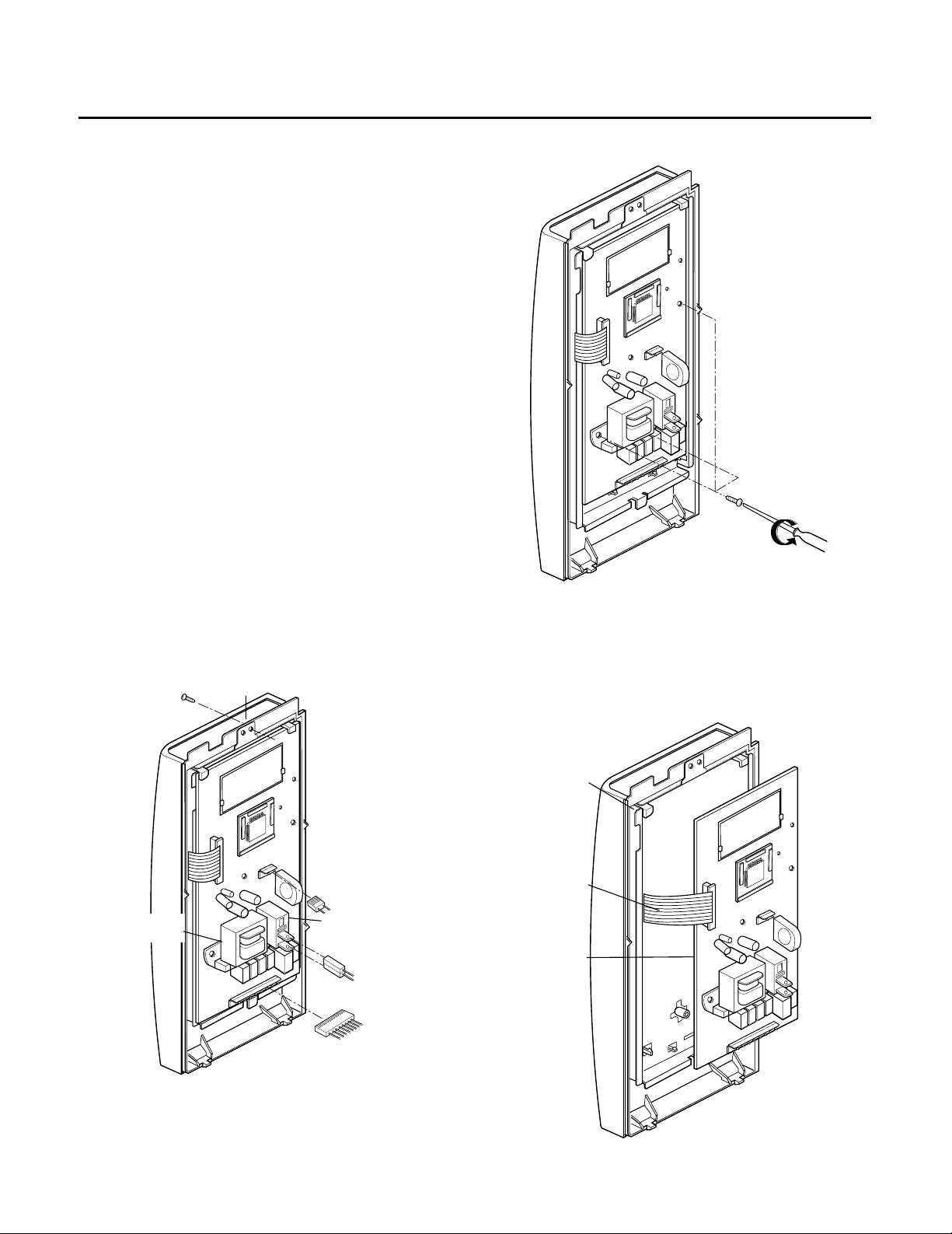
A. REMOVING POWER AND CONTROL
CIRCUIT BOARD (Figures 1, 2 and 3)
(1) Remove a screw securing the control panel
assembly to the oven cavity.
(2) Remove the control panel with pushing it upward.
(3) Remove the three connectors (CN1, CN2) and
wire leads (Relay2) from the circuit board.
(4) Remove 3 screws securing the circuit board.
(5) Remove the FPC connector from the terminal
socket following “HOW TO REMOVE THE FPC
CONNECTOR” on the next page.
(6) Remove the circuit board from the control bracket
carefully.
7-4
Circuit Board
FPC Connector(S1)
Control Bracket
Circuit Board
Figure 1
Figure 2
Figure 3
DISASSEMBLY INSTRUCTIONS
Control Panel
Screw
Power
Transformer
Relay 2
(CN2)
(CN2)
(Relay 2)
(CN1)
7-5
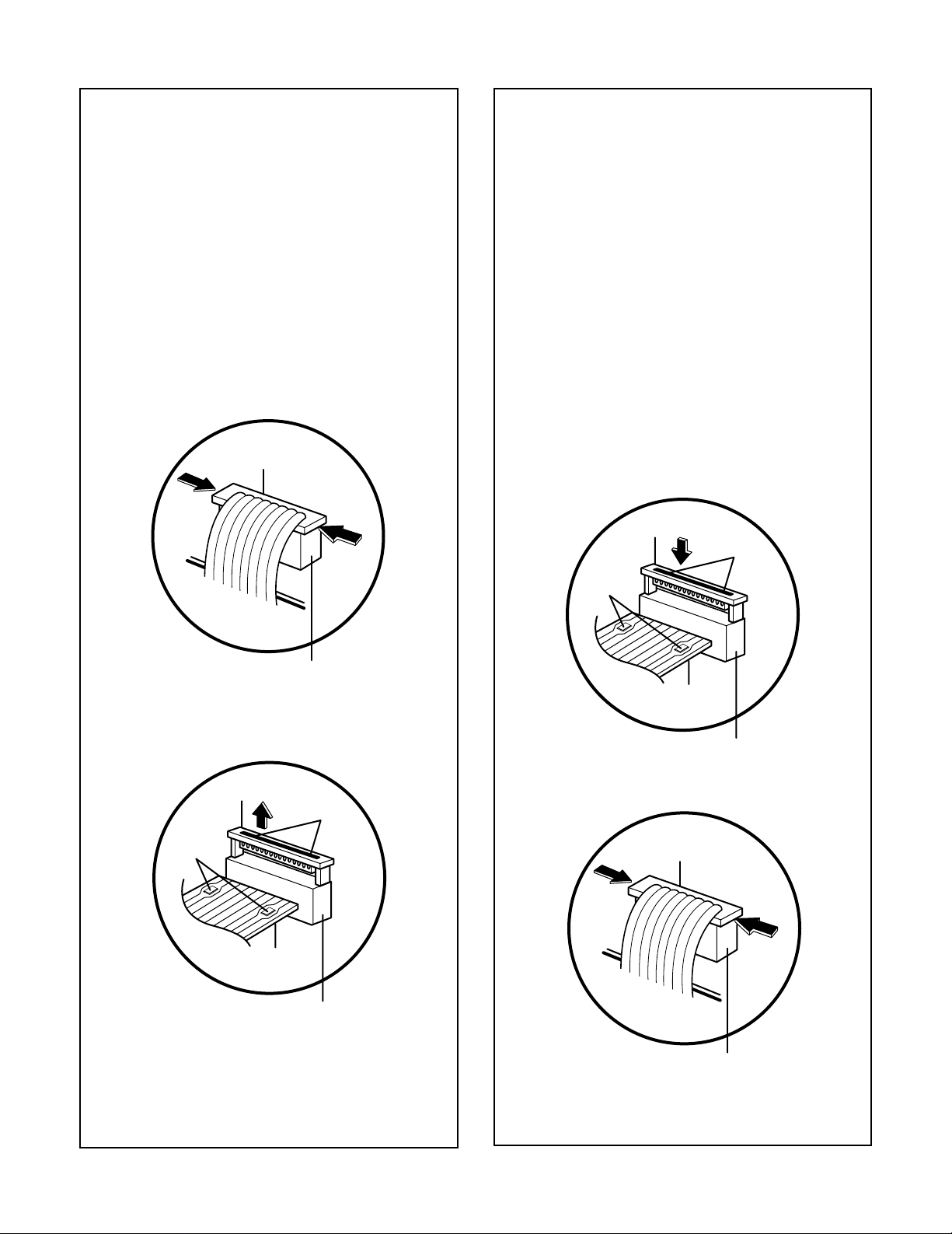
HOW TO REMOVE THE F.P.C. CONNECTOR
Follow the steps below as illustrated in Figures 4
and 5 to remove the F.P.C. connector.
(1) Hold the edges of the plastic fastener with
thumb and forefinger.
(Figure 4)
(2) Lift up the lever of the plastic fastener from
the terminal socket by lightly pressing the
lever end with forefinger.
(Figure 5)
(3) Remove the F.P.C. connector from the
terminal socket.
HOW TO INSERT THE F.P.C. CONNECTOR
Follow the steps below as illustrated in Figures 6
and 7 to insert the F.P.C. connector.
(1) Insert the F.P.C. connector into the terminal
socket securely with the fingers.
(2) Hold the plastic fastener with thumb and
forefinger of the other hand, and push it
slowly into the terminal socket. (Figure 6)
NOTE: When reconnecting the F.P.C
connector make sure that the holes
on the F.P.C. connector are properly
engaged with the hooks on the plastic
fastener
(3) Lock the level of the plastic fastener into the
hook of the terminal socket securely by
releasing the fingers.
(Figure 7)
Figure 4
Figure 7
Figure 6
Figure 5
Plastic fastener
Plastic fastener
Hook
F.P.C.
Connector
Plastic fastener
Holes
Terminal
socket
F.P.C.
Connector
Hook
Terminal
socket
Holes
F.P.C.
Connector
Terminal
socket
Plastic
fastener
F.P.C.
Connector
Terminal
socket
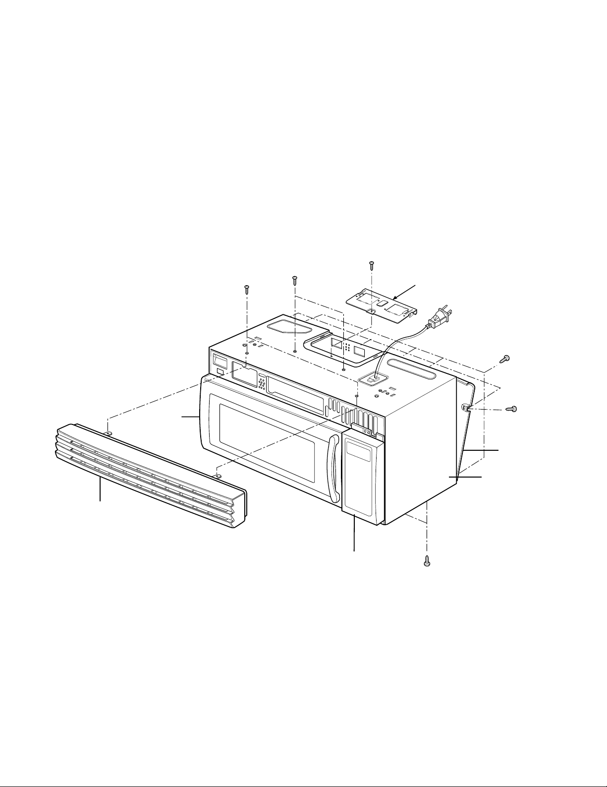
B. REMOVING THE OUT CASE(Figure 8)
(1) Remove the vent grille by removing two screws
securing it to the out case.
(2) Remove two screws securing it to the air duct.
(3) Remove the mounting plate by turning the screws
(1 or 2 screws) securing it to the out case.
(4) Remove two screws on the left central edge and
one screws on the right central edge of Base
plate. Remove the Mount, All from the out case by
removing one screw securing it to the out case.
(5) Remove the outcase with disconnecting power
cord connector.
Vent Grille
Controller
(3 screws)
Door
Mounting
Plate
(1 or 2 screws)
Out Case
Mount,All
Figure 8
7-6
 Loading...