

Page 1
GOLDSTAR GSX408/816 http://www.britishtelephones.com/goldstar/gsx408.ht
m
The GSX-408/816 Key Telephone System is designed to meet the telecommunications needs of small to
medium sized businesses.
The Key Service Unit (KSU) is a wall mountable unit that contains Key Service Board, Power Supply,
Battery Backup Unit, Real Time Clock Unit and pre-wired connectors for station and CO line interfaces.
The GSX-408/816 is a flat pack system equipped with 4 CO lines and 8 Stations. It can be easily
expanded to 8 CO lines and 16 stations with a modular PCB mounted in the KSU.
Crane Telecommunications are the sole importer of these systems into the UK. Goldstar UK have nothing
to do with them what so ever. Installation manuals are scarce due the fact Crane Telecommunications
operated maintenance contracts on the systems and were reluctant to let the owners carry out their own
re-programming. If the system is second-hand you will have trouble getting any support for it at all.
Y2K Compliant.
The GSX-408/816 Key Telephone system is a microprocessor controlled, solid state electronic switching
system which distributes communications in a non-blocking format. All control, switching interface
circuitry is condensed onto a single printed circuit board (PCB) located inside the key service unit.
Switching is accomplished through a solid state crosspoint matrix that provides voice path connections for
4 (8) central offices lines, 8 (16) key telephones and 8 intercom paths.
The CO interfaces are equipped with transformer barriers for system classification as an FCC fully
protected system. Each CO circuit supports rotary or DTMF dialing under software control. The DTMF
tones and system supervisory tones are generated in each keyset.
The central microprocessor is a Z-80 and controls the crosspoints and central office relays. It also controls
communications between slave microprocessor located in each GSX key telephone.
The 408/816 contains all system memory, which is composed of 96K of Read Only Memory (ROM) and
16K of Random Access Memory (RAM). The RAM is sub-divided so that part is used for customer
database. A long life lithium battery protects the customer database memory. The system general
memory (ROM) is contained in a Program Module (PM) that is interfaced to the KSU through a modular
connecting arrangement. This allows easy access for removal of system software when upgrading
software feature packages.
Each key telephone contains a microprocessor and circuitry to monitor button activity and control lamp
conditions. A built-in speaker permits voice or tone calling to the station. Every telephone has a flexible
button field, which can be individually programmed for 1 to 6 functions.
The key telephone sets are equipped with 9 fixed function buttons and either 12 or 24 flexible buttons
which can be programmed by individual users, 2 volume controls an intercom mode selection switch and
integrated speaker.
1 de 8 12/06/2010 09 :17 a.m.
Page 2

GOLDSTAR GSX408/816 http://www.britishtelephones.com/goldstar/gsx408.ht
m
For emergency applications, a stand-alone battery assembly may be connected to the battery-input
terminals on the KSU. This retains system power in the event of commercial power failure.
8 CO (Outside) Lines
8 Intercom Channels
16 Key Telephone Stations
1 External Music Source Input
1 External Paging port
2
Loud Be ll C on trols
1 Alarm Input (NOT BURGLAR ALARMS!)
1 24V DC Battery Connector
OPTIONAL
1 RS232C Port for SMDR
KEY SERVICE UNIT
The KSU is a self-contained unit that contains the power
supply, processor, external connectors and circuits for 4
CO lines and 8 stations. External connections use 50way
Telco connectors. A plug in module provides systemoperating data in standard and advanced feature package.
The system is provided with a real time clock to provide
executive telephones with LCD, to have time and date
displayed, and a battery to keep clock accurate in case of
commercial power failure. This unit also provides SMDR
to track date and time.
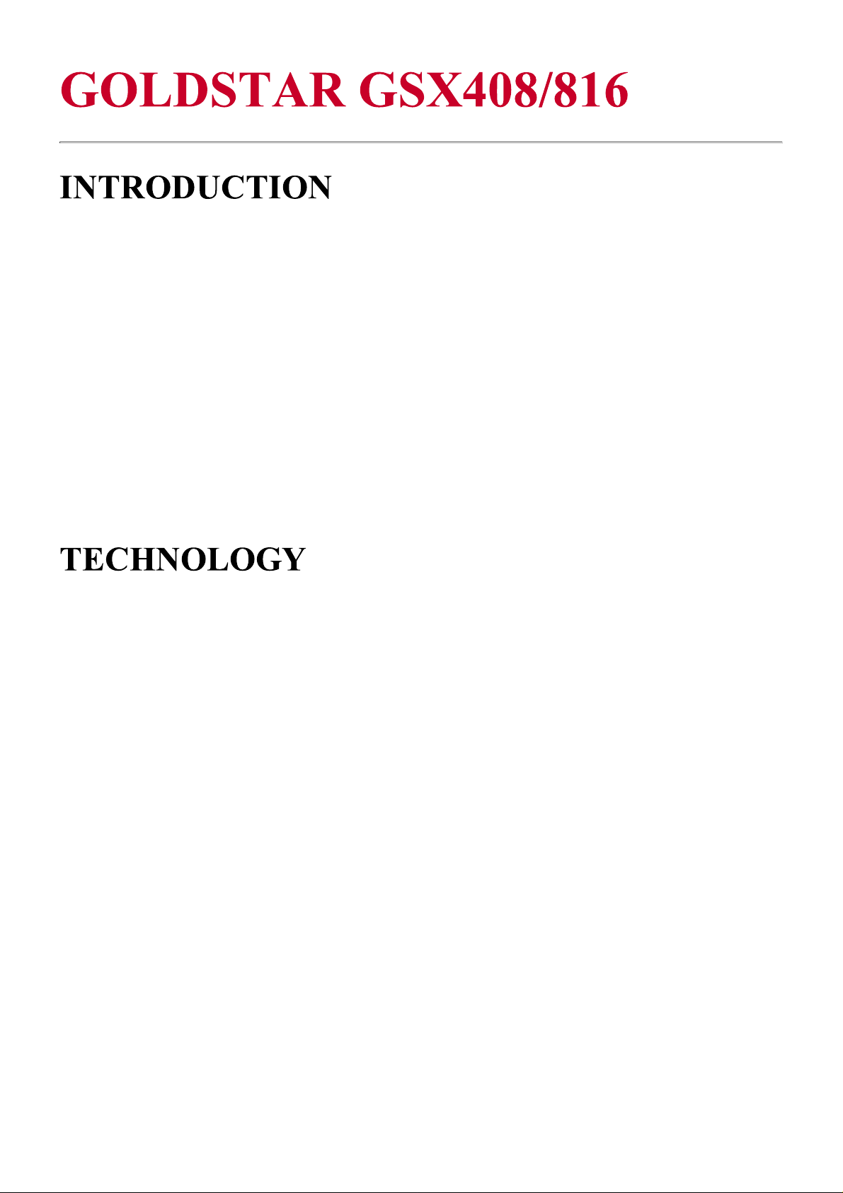
KEY TELEPHONE
The 4-button telephone comes with 4 fixed feature buttons.
1 volume control and message waiting lamp.
The 8 button has the same size wit 4-button telephone but comes with 2 fixed feature buttons, 6
programmable buttons, 1 volume control and message waiting lamp.
The 21-button telephone comes in 2 models, Enhanced and Executive. Both models come with 9 fixed
feature buttons, 12 programmable buttons, speakerphone, 2 volume controls, and intercom mode selection
switch. In addition, the Executive model comes with a 2-line, 48-character LCD display.
The 33 button is similar to the 21-button but comes with 24 programmable buttons. Is also available in
enhanced and executive style.
2 de 8 12/06/2010 09 :17 a.m.
Page 3
GOLDSTAR GSX408/816 http://www.britishtelephones.com/goldstar/gsx408.ht
m
4 Button Key Telephone 21 Button Key Telephone
PHONE BOX
The unit is basically a wall-mounted unit that is used for door-opening facilities. The system can handle a
maximum of 8 of these units.
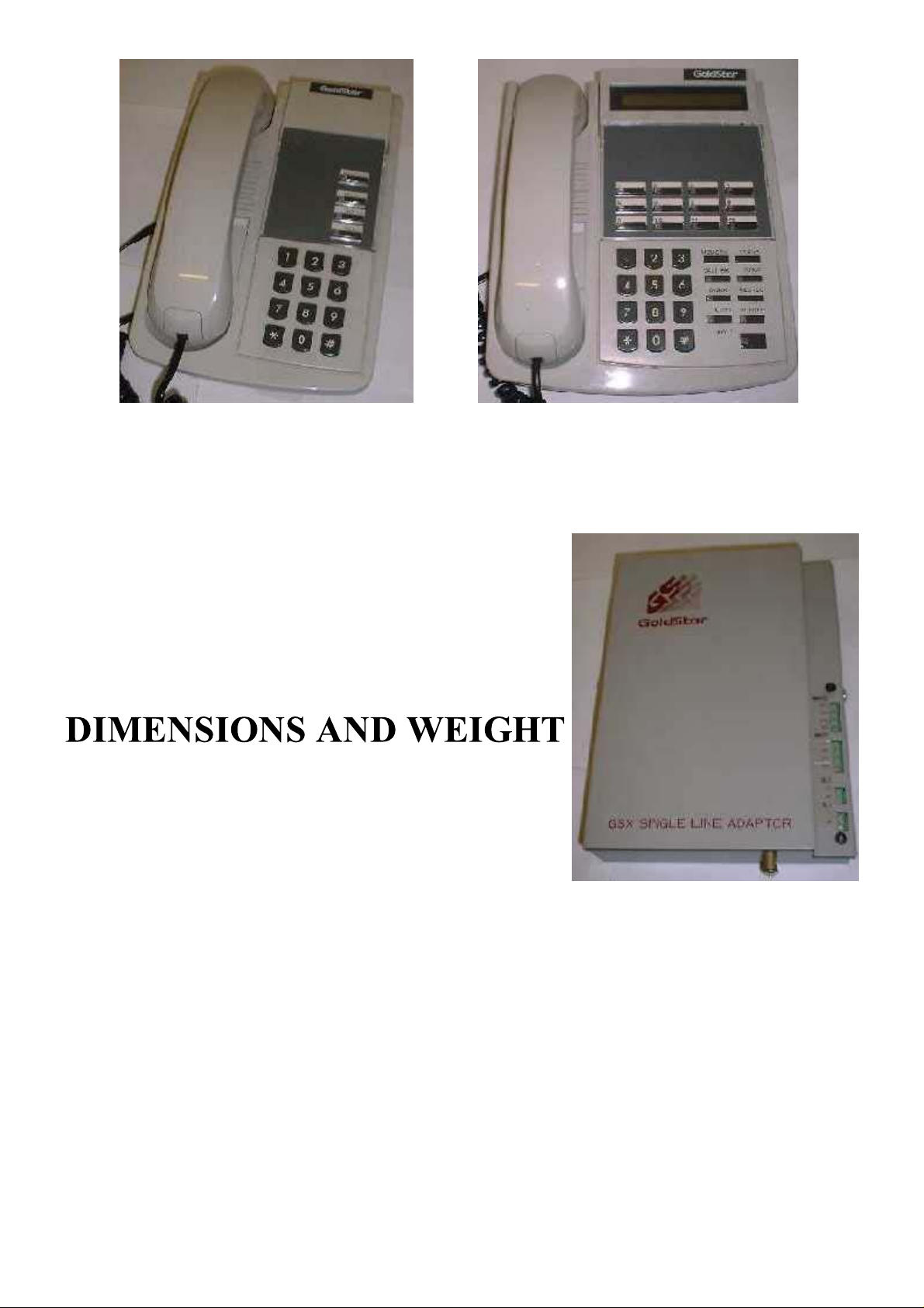
SINGLE LINE ADAPTOR
This unit (shown pictured to the right) is for converting connection
that would be intended for a key telephone and convert the signals
so that a normal POTS telephone can attached to the system i.e.
modem, answer phone etc. etc.
KEY SERVICE UNIT
Height 419mm
Width 298mm
Depth 76mm
Weight 8KG
KEY TELEPHONE
Height 222mm
Width 222mm
Depth 70mm
Weight 1.5KG
PHONE BOX
Height 44mm
Width 140mm
Depth 102mm
Weight 0.5KG
EXPANSION MODULE
Height 279mm
Width 140mm
Depth 25mm
3 de 8 12/06/2010 09 :17 a.m.
Page 4

GOLDSTAR GSX408/816 http://www.britishtelephones.com/goldstar/gsx408.ht
m
Weight 0.8KG
100-115 Station Numbers
250-255 Call Park locations
260-267 Hunt Group Pilot Numbers
281 (ATND)
WAKEUP Registration-effective until
cancel
282 (ATND) WAKEUP Registration-one time only
283 (ATND) WAKEUP Cancel
284 (ATND) PASSWORD Erase
285 (ATND) LCD Format-ddmmyy/mmddyy (toggle)
286 (ATND) LCD Format-am-pm/24 hour (toggle)
299 (ATND) Clock
3 Camp On (Call Wait)
CO LINES
The CO Lines are connected to the RHS of the KSU on a 50 Way Telco connector.
PAIR CO Line COLOURS
11 BLUE / WHITE
2 2 ORANGE/WHITE
3 3 GREEN/WHITE
44 BROWN/WHITE
55 GREY/WHITE
66 BLUE/RED
7 7 ORANGE/RED
8 8 GREEN/RED
PAIR CO POWER FAIL COLOURS
21 1 BLUE/PURPLE
22 2 ORANGE/PURPLE
23 3 GREEN/PURPLE
24 4 ORANGE/PURPLE
Pairs 21-24 provide CO lines 1-4 back out of the system if there is a power failure. They will not show
current if the system is powered up.
STATION WIRING
Normally when the systems are installed for the first time, the supplier will have connected the pairs to
KRONE IDC strips. Extension 100 will be on the first 2 pairs of the loom (Blue/White and
Orange/White). The rest of the extensions will follow on until Extension 107, for extension 108 to 115 the
loom cable will be the same as before but just plug it into the connector on the KSU for that extension
range. For the wiring of cables to a PSTN socket for extension 100, it is like so: -
4 de 8 12/06/2010 09 :17 a.m.
Page 5

GOLDSTAR GSX408/816 http://www.britishtelephones.com/goldstar/gsx408.ht
m
PSTN
WHITE/BLUE -
OUTLET
PIN #4
PSTN
BLUE/WHITE -
OUTLET
PIN #3
PSTN
WHITE/ORANGE -
OUTLET
PIN #5
PSTN
ORANGE/WHITE -
OUTLET
PIN #2
You will need to have a lot creative license to finally get all the rest of the stations wired up but it is fairly
easy if you follow the standard that is used for extension 100.
Do not use PSTN Master sockets as they make the KSU/KEY Phone appear to be faulty when it isn’t only
use secondary sockets.
If you wire the socket up incorrectly you may get no response or possibly a full LCD screen test combined
with interference sounds emitted from the speaker, then all goes dead on the handset
MUSIC ON HOLD / EXTERNAL PAGING
The connections on the side of the KSU for these inputs and outputs are fairly well UN-DOCUMENTED!
On the wiring loom for the extensions, pair 17 (ORANGE/YELLOW) are for connection of a of music
device e.g. CD-Player, Radio etc. etc. Pair 18 is for connection to an external P.A system.
To enter program mode dial *7764 from station 100. When programming it advisable to use an executive
21//33 key telephone. Programming can be achieved by using an enhanced but the LCD gives on-screen
guidance.
To enter the programming menus press the recall button followed by the 2-digit program code.
Some menus appear twice but when they are entered into, they actually adjust different parameters even
though they look the same.
This section provides all the programming codes for the system. Some codes have sub menus so be
thorough.
Key Use
1 System Hold Re-Call
2 Exclusive Hold Re-Call
3 Transfer Re-Call
4 Preset Forward Timer
5 de 8 12/06/2010 09 :17 a.m.
Key Use
21
22 Pul se Dialing Parameter s
23
24
Page 6

GOLDSTAR GSX408/816 http://www.britishtelephones.com/goldstar/gsx408.ht
m
5Pause Timer
6 Call Park Timer
7
8 Message W ait in g Tone Timer 28 Date & Time
9 Paging Time Out
10 CO Rin g De tect
11 Hol d Preferenc e
12
13 Ext N igh t Ring
14
15 Atten dant Stat ion Assignmen t 35
16 Loud Bel l Assignmen t
17 PBX Dial Codes
18 Executive Secr et ar y Pairings 38
19 Hu nt Gr oups
20 SMDR Paramet ers
25 I CM Box Timer ( Door Phone)
26
27 Background Mu s ic Ch annel
29 Mon itor M ode
30 CO Line Attribut es
31
32
33 Attendant Re-Call
34
36
37
39 Mu l t i Lin e Con f er encing
40 Station Attribut es
Key Use
41
42
43
44
45
46
47
48 SMDR T imer
49 SMDR Lon g Distance Codes
50 Except ion Tables
51
New Tel. No P lan
52 Station At t r ibu t es
53
54
55
56 CO De lay Timer
57
58
59
60 I nitialize System Param et er s
Key Use
61 I nitializ e CO Lin es
62 I nitializ e Stat ions
63 I nitialize Exclu sion Tabl es
64 I nitializ e System Speed N umbers
65
66
67
68
69
70 Print System Data
71 Print System Parameters
72 Print CO Lin es
73 Print St a tion s
74 Print EX Tables
75 Print System Speed N o
76 Print Least Cost Rou t ing
77 Print N ew ST D Tables
78
79
80
Key Use
81 Least Cost R outing Enable
82 I nhibit BT Access
83 LCR Access Codes
84 LCR Authorization Codes
85 LCR Dial Tone Detect T im er
86 LCR Looku p Table
87 New Mer cury STD Tabl e
88 MCL Ext ension Bill in g
89 Disable 30 Sec
90
91 Paging T imeout
92
93 Mon itor M ode
6 de 8 12/06/2010 09 :17 a.m.
Page 7

GOLDSTAR GSX408/816 http://www.britishtelephones.com/goldstar/gsx408.ht
m
94
95 SMDR Lon g dist ance Codes
96
97
98
99 Disable 30 Sec
100
Extens i o n 10 0
-107 Loom
Extens i o n 10 8
-115 Loom
CO Line Loom
Pair Colour PIN Use
1White/Blue 4
1Blue/White 3
2 White/Orange 5 100
2 Orange/White 2
3 White/Green 4
3 Green/White 3
4 White/Brown 5 101
4 Brown/White 2
5White/Grey 4
5Grey/White 3
6 Red/Blue 5 102
6Blue/Red 2
7 Red/Orange 4
7 Orange/Red 3
8 Red/Green 5 103
8 Green/Red 2
9 Red/Brown 4
9Brown/Red 3
10 Red/Grey 5 104
10 Grey/Red 2
11 Black/Blue 4
11 Blue/Black 3
12 Black/Orange 5 105
12 Orange/Black 2
13 Black/Green 4
13 Green/Black 3
14 Black/Brown 5 106
14 Brown/Black 2
15 Black/Grey 4
15 Grey/Black 3
16 Yellow/Blue 5 107
16 B lue/Yellow 2
17 Yellow/Orange Music
17 Orange/Yellow On-Hold
18 Yellow/Green External
18 Green/Yellow Paging
19 Yellow/Brown N/A
19 Brown/Yellow
20 Yellow/Grey N/A
20 Grey/Yellow
21 Purple/Blue N/A
Ext
Ext
Ext
Ext
Ext
Ext
Ext
Ext
N/A
N/A
Pair Colour PIN Use
1White/Blue 4
1Blue/White 3
2 White/Orange 5 108
2 Orange/White 2
3 White/Green 4
3 Green/White 3
4 White/Brown 5 109
4 Brown/White 2
5White/Grey 4
5Grey/White 3
6 Red/Blue 5 110
6Blue/Red 2
7 Red/Orange 4
7 Orange/Red
8 Red/Green 5 111
8 Green/Red 2
9 Red/Brown 4
9Brown/Red 3
10 Red/Grey 5 112
10 Grey/Red 2
11 Black/Blue 4
11 Blue/Black 3
12 Black/Orange 5 113
12 Orange/Black 2
13 Black/Green 4
13 Green/Black 3
14 Black/Brown 5 114
14 Brown/Black 2
15 Black/Grey 4
15 Grey/Black 3
16 Yellow/Blue 5 115
16 B lue/Yellow 2
17 Yellow/Orange N/A
17 Orange/Yellow
18 Yellow/Green N/A
18 Green/Yellow N/A
19 Yellow/Brown N/A
19 Brown/Yellow
20 Yellow/Grey N/A
20 Grey/Yellow N/A
21 Purple/Blue N/A
3Ext
Ext
Ext
Ext
Ext
Ext
Ext
Ext
N/A
N/A
Pair Colour Use
1White/Blue CO 1
1Blue/White
2 White/Orange CO 2
2 Orange/White
3 White/G r een CO 3
3 Green/White
4 Wh ite/Brown CO 4
4 Brown/White
5White/Grey CO 5
5Grey/White
6 Red/Blue
6Blue/Red CO6
7 Red/Orange
7 Orange/Red
8 Red/Green CO 7
8 Green/Red
9 Red/ Br own CO 8
9Brown/Red
10 Red/Grey N/A
10 Grey/Red N/A
11 Black/Blue N/A
11 Blue/Black N/A
12 Black/Orange N/A
12 Orange/Black N/A
13 Black/Green N/A
13 Green/Black N/A
14 Black/Brown N/A
14 Brown/Black N/A
15 Black/Grey N/A
15 Grey/Black N/A
16 Y ellow/Blue N/A
16 Blue/Yellow N/A
17 Yellow/Orange N/A
17 Orange/Yellow N/A
18 Yellow/Green N/A
18 Green/Yellow N/A
19 Yellow/Brown N/A
19 Brown/Yellow N/A
20 Yellow/Grey N/A
20 Grey/Yellow N/A
21 Purple/Blue CO 1
7 de 8 12/06/2010 09 :17 a.m.
Page 8

GOLDSTAR GSX408/816 http://www.britishtelephones.com/goldstar/gsx408.ht
m
21 Blue/Purple
22 Purple/Orange N/A
22 Orange/Purple
23 Purple/Green N/A
23 Green/Purple
24 Purple/Brown N/A
24 Brown/Purple
25 Purple/Grey N/A
25 Grey/Purple N/A
N/A
N/A
N/A
N/A
21 Blue/Purple
22 Purple/Orange N/A
22 Orange/Purple N/A
23 Purple/Green N/A
23 Green/Purple
24 Purple/Brown N/A
24 Brown/Purple N/A
25 Purple/Grey N/A
25 Grey/Purple N/A
N/A
N/A
21 Blue/Purple Power Fail
22 Purple/Orange CO 2
22 Orange/ Purple Power Fail
23 Purple/G r een CO 3
23 Gr een/Pu r pl e Power Fail
24 Purple/Brown CO 4
24 Brow n/Purple Power Fail
25 Purple/Grey N /A
25 Grey/Purple N/A
Installation of extra lines
When configuring extra lines, the system has to be told that extra lines exist ( program code 30). Then the
function buttons on the keyphones need to be reassigned (program code 40, second command page).
Thanks to Nick Davies for this page
BACK Home page
BT/GPO
Telephones
A - Z Index
Ericsson
Pages
Quick Find
All Telephone
Systems
Last revised: 21 March, 2002
8 de 8 12/06/2010 09 :17 a.m.
 Loading...