

Page 1
- 2-1 -
SECTION 2. ELECTRICAL
TROUBLESHOOTING
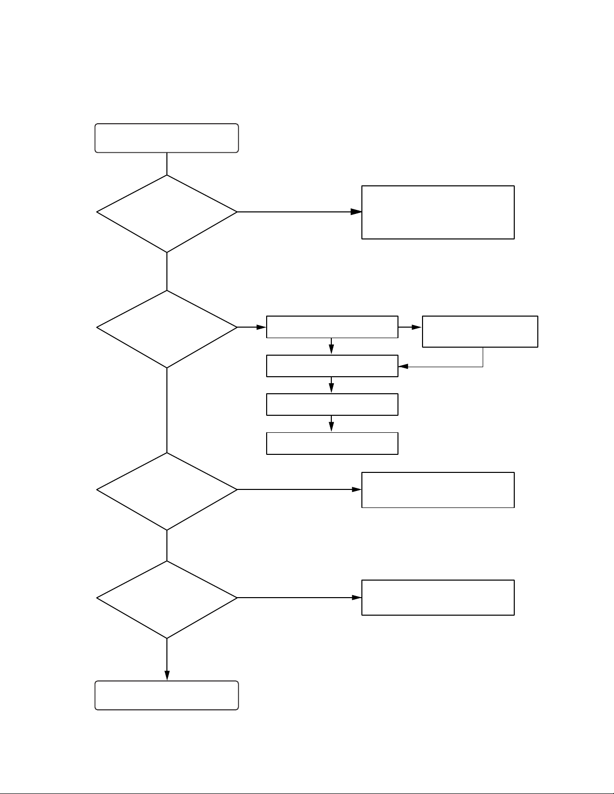
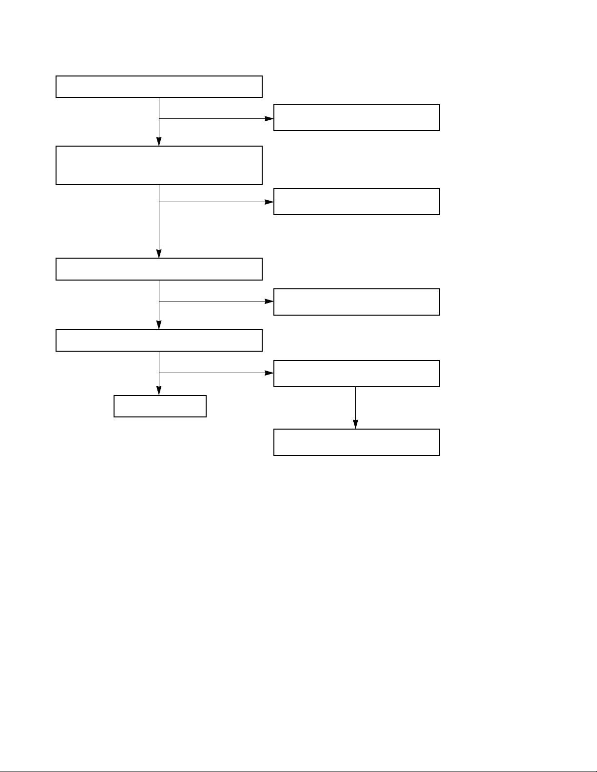
Turn power on.
Is power on?
Does initial read work?
Does it play?
Does it output audio?
Check power supply circuit.
PN508 PIN 8, 6.2V
PN508 PIN 7, 5V
IC503 PIN 2, 3.3V
Check the connector
PN503, PN504, PN507
Check the tracking servo circuit.
Check the PN508 PIN1, 3
OK
YES
YES
YES
YES
YES
YES
YES
YES
NO
NONO
Check the DISK turns
Check the Laser
Check the focus circuit
Check the TRAKING circuit
NO
NO
Page 2
- 2-2 -
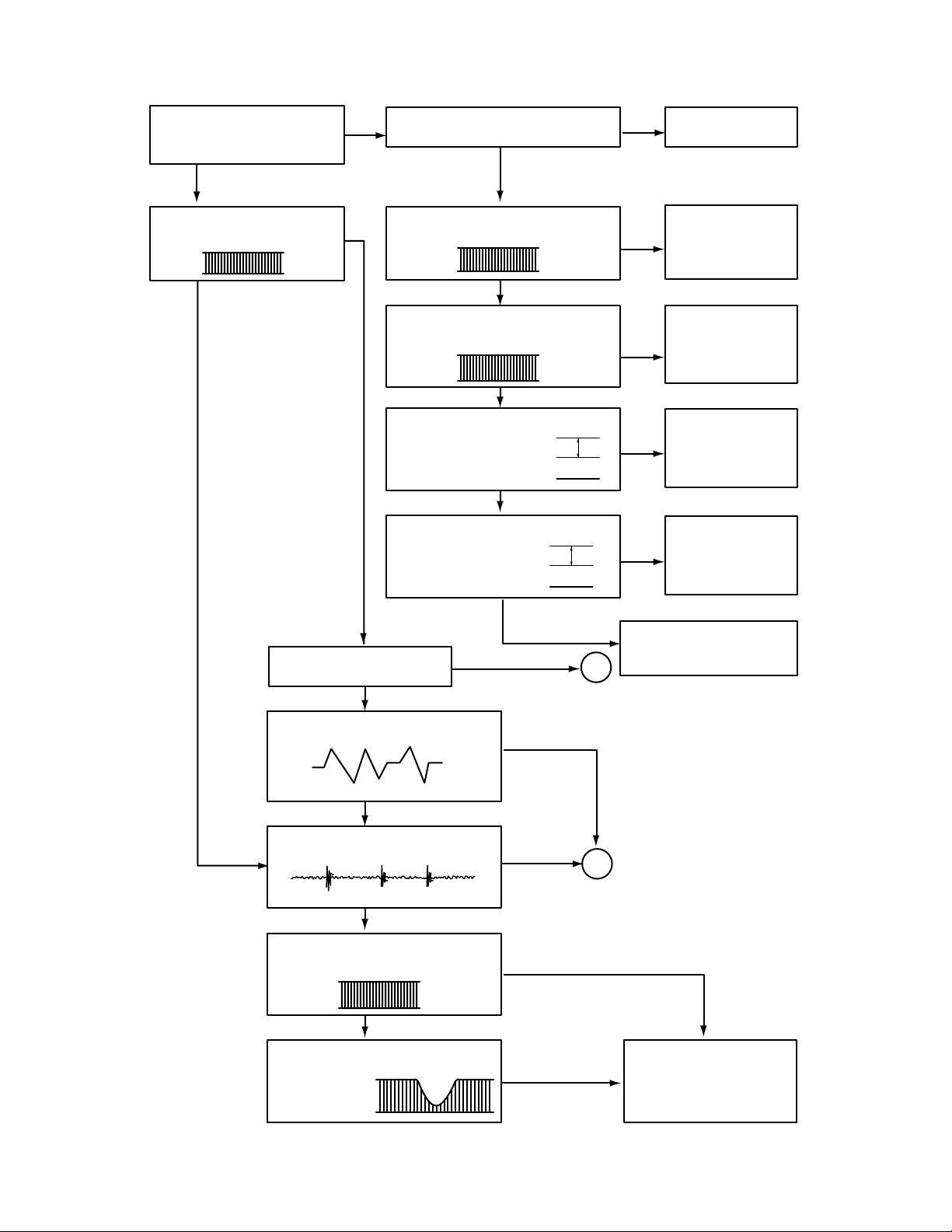
Fails to initial read
A
B
2V
5V
0V
5V
0V
1V
0V
1.2V
0V
0.8V
NO NO
NO
NO
NO
NO
NO
NO
YES
YES
YES
YES
YES
YES
YES
YES
YES
YES
YES
YES
Disc motor turns
Does RF waveform appear?
IC501 Pin4
Check the Data transmission from
PN507 pin8 to CD DSP
Check the Data transmission from
PN507 pin6 to MICOM
Check the change of SLDO
Voltage(IC501 pin23)
Check the change of SL +,
SL - Voltage
(IC502 pin 18, 19)
Check the Voltage change of PN 507
pin2(OPEN, CLOSE)
Defective connector
PN507
Defective connector
PN507 Defective
MICOM
Defective connector
PN507 Defective
IC501
Defective IC501
Defective IC502
Defective contact PN503
Defective PICK-UP
Does laser light?
focus coil drive wareform.
TRACKING ERROR wareform
Is rotation normal?
Defective IC501
Defective PICK-UP
Is there no dropout of RF signal?
Does FA+ waveform appear at
IC502 pin13?
Does TE waveform appear at
501 pin 15?
Page 3
- 2-3 -
NO
NO
NO
NO
NO
NO
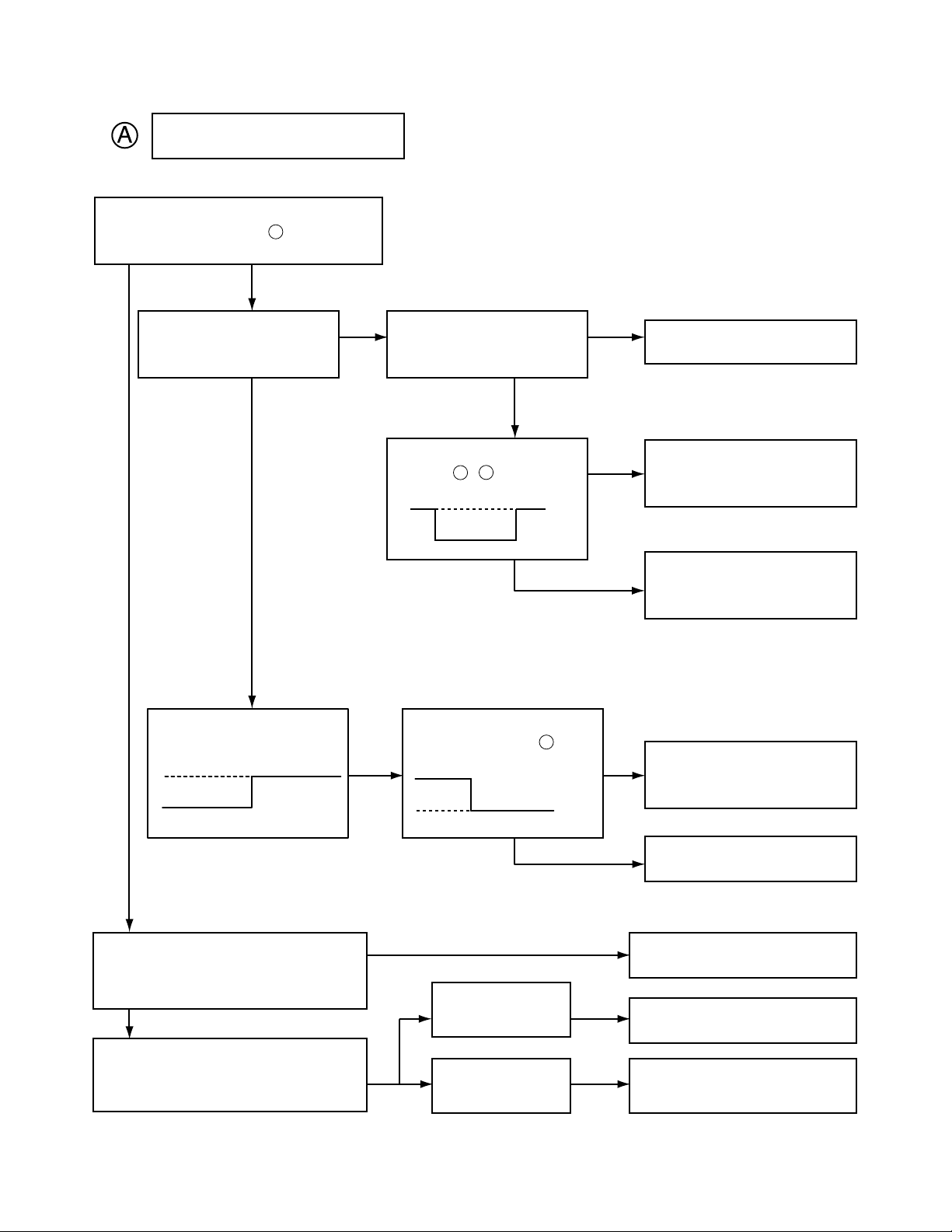
Laser does not light.
Is “5V” applied to pin of IC 501?
Is power supplied to laser Q501?
(Q 501 collector: about 1.8V)
Does laser current flow?
1.0V across R508
Is data transferred from
MICOM IC ?
Does voltage appear at IC
502 pin , ?
Defective MICOM.
Defective MICOM.
Defective connector.
Defective IC 501, 502
Defective slide motor and/or
connector.
Defective LMT SW and/or
connector.
Defective Q 501 and/or laser.
Defective laser and/or
connector.
Did pickup return to
innermost circular?
Does it stop at inner pick
circular after shift?
Is defect output from LM
SW applied to pin of
PN503?
R508 »1.0V
R508 «1.0V
YES
YES
YES
YES
OPEN
CLOSE
YES
YES
YES
YES
YES
YES
66
18
19
3
Page 4
- 2-4 -
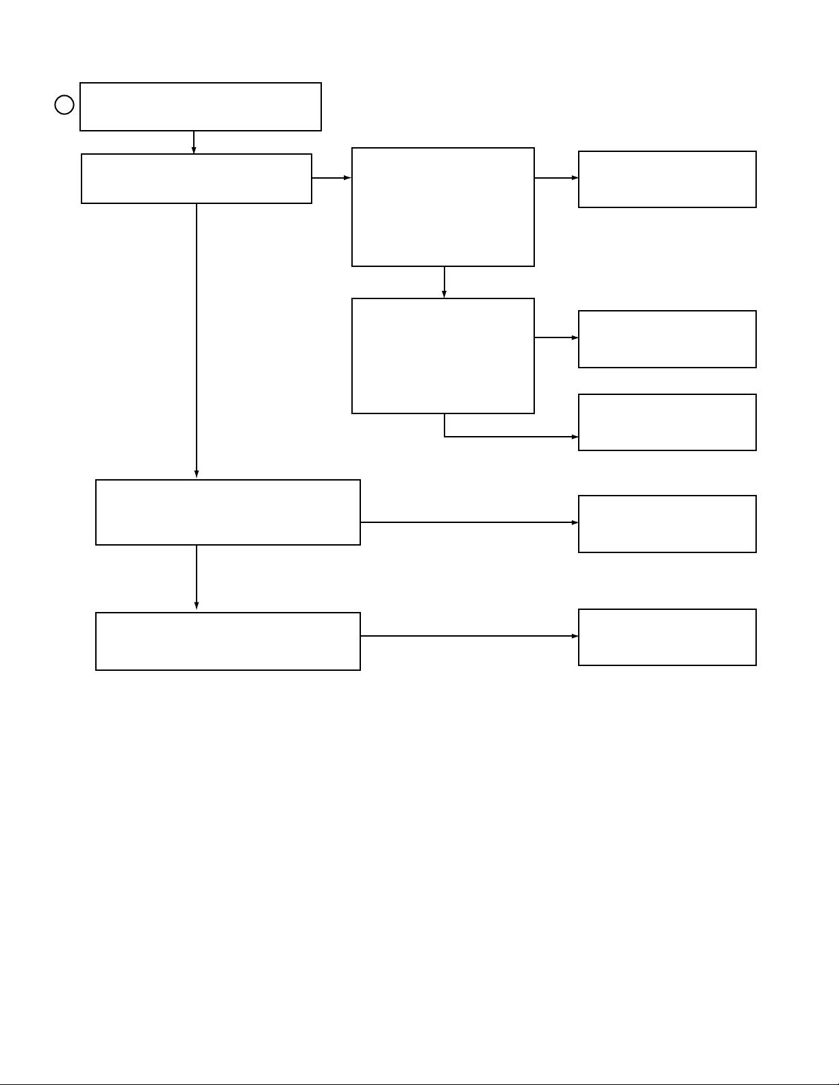
B
NO
NO
NO
NO
NO
YES
YES
YES
YES
Laser lights
Does lens move up/down?
Check the signal of
FOCUS SEARCH
(IC501 Pin 21)
Chekc the signal of PN502
pin 13, 14
Does FE signal appear?
(IC501 pin 13)
Does DRF signal appear? (IC 501 pin67)
Defective IC501
Defective IC502
Open activator and/or connector
Defective IC501
Degraded laser diode
Defective PICK-UP
Page 5

- 2-5 -
(CH1)
(CH2)
WAVEFORMS OF MAJOR CHECK POINT
1. HF signal (RF signal ) waveform
(IC501 pin 4) during normal play
2. EFM signal (IC501 pin 3)waveform
during Normal Play
3. Focus coil drive waveform(IC502 pin13)
• When focus search failed or there is no disc on the tray
• Focus coil drive waveform(FDO: IC501 pin21) and
DRF(IC501 pin67) when focus search is accomplished
4. Tracking coil drive waveform and TE during track
traverse
(1) When time division is 20mS/Div.1V/Div.
(2) When time division 1mS/Div, 1V/Div
(During forward track traverse)
(3) When time division is 0.5nS/div.
(During backward Track Traverse)
5. Feed motor drive waveform(IC 502 pin18)
During normal play
CH1 : FOCUS COIL DRIVE
SIGNAL 2V/Div.
CH2 : DRF
CH1 : TRACKING COIL DRIVE
SIGNAL 2V/Div. (IC502 pin27)
CH2 : TRACKING ERROR(TE: IC501 pin15)
1V/Div.
(
(
(
CH1 : TRACKING COIL DRIVE (IC502 pin27)
SIGNAL 2V/Div.
CH2 : TRACKING ERROR (TE: IC501 pin15)
1V/Div.
(
CH1 : TRACKING COIL DRIVE (IC502 pin27)
CH2 : TRACKING ERROR (TE: IC501 pin15)
(
0.5V/Div.
500nS/Div.
(
1S/Div.
1V/Div.
(
1mS/Div.
1V/Div.
(
0.5V/Div.
5µS/Div.
(
2S/Div.
0.5V/Div.
0V
0V
0V
(CH1)
(CH2)
(CH1)
(CH2)
(CH2)
0V
0V
0V
0V
0V
0V
0V
0V
0V
Page 6

- 2-6 -
P-SENS PART
Does +5V appear at ZD702?
Check the pattern of
IC301 Pin .
Check the waveform
of D706 (+).
Check the R718 and
replace ZD702.
Replace the D706
YES
YES
NO
NO
26
Power Circuit
Check the Fuse
Check the DC output
of C715(+), C716(-)
Check the DC
Output of IC702
Check the DC 12V
output of IC703
Check the DC 6.2V
output of IC704
END
Replace the Fuse
Check the AC output of
PN601 pin 1, 3
Check the D701
Check the D713
Replace the Transformer
Check the voltage of
IC302 pin 2
YES
YES
YES
YES
YES
NO
NO
NO
NO
NO
Page 7

- 2-7 -
Muting circuit (MUTE)
Dose “High” appear at
Q701, Q751, Q706, Q707,
Q709
Check the “Low” of Q701,
Q706, Q707, Q709, Q751, “C”
MUTE
Check the “HIGH” of IC301 pin9
(ONLY Q706, Q707, Q709)
Check the “High” of the Q702 “E”
(ONLY Q701, Q751)
Replace the Q702
Replace the TR
Refer to IC 301
Troubleshooting
YES
YES
YES
NO
NO
NO
Audio abnormal
Check the output of
IC400 Pin 26, 27
Refer to “IC400
Troubleshooting”
Refer to “Muting
Troubleshooting”
Check the power Circuit
Check the “LOW” of IC301
pin24
Check the input of
IC701 Pin 7, 11
Check the output of IC701
pin2, 4
Check the “LOW” of CN704
pin5
END
YES
YES
YES
YES
NO
NO
NO
NO
Page 8

- 2-8 -
FUNCTION MODE Audio abnormal
AUX
Chekc the signal input of IC400, pin 3, 4
Check the signal input of JK401
Check the signal input of IC400 pin 1, 6
Check the signal of PN703 pin 6, 8 or
Refer to “CD Troubleshooting”
Check the signal input of IC400 pin 2, 5
Refer to “IC102 Troubleshooting”
CD
Tuner
Page 9

- 2-9 -
Refer to “IC301
Troubleshooting”
IC301 Troubleshooting
IC400 Troubleshooting
Check the power supplying IC301 Pin 17, 54, 90?
Refer to “Power Circuit Troubleshooting”
Check the P-SENS
Replace the X301
Check the RESET circuit
Refer to “Power Circuit Troubleshooting”
Check the PIN of MICOM 4, 5
Replace the IC400
Replace the IC400
Check the pattern
of MICOM (4, 5)- IC400
(21, 22)
Check the 5V of IC301 pin 26
Check the oscillation of X301
When power supplying to IC301 pin11.
(Low ➞ High)
Replace the IC301
Check the power supplying to IC400 pin24
Check the CLK Data of IC400 pin 21, 22
Check the waveform output of IC400 pin 8, 10
Check the waveform input of IC400 pin9, 11
Check the waveform output of IC400 pin26, 27
END
YES
YES
YES
YES
YES
YES
YES
YES
NO
NO
NO
NO
NO
NO
NO
NO
Page 10

- 2-10 -
FM (TUN101)
Check the +12V input of TUN101 B+ 6
Check the “High” Voltage of TUN101 VT 5
Check the OSC waveform of TUN101 Pin 8
Refer to “IC102 Troubleshooting”
Check the 12V of Q102 “E”
Refer to “Power
Circuit Trouble-
shooting”
Check the “GND” of IC103 Pin 7
Refer to “IC103
Troubleshooting”
Replace the Q102
Replace the TUN101
Replace the TUN101
YES
YES
YES
YES
YES
NO
NO
IC102 Troubleshooting
Check the power supplying to pin8
Check the waveform of Pin 20, 21
Check the waveform output of Pin 16, 17
END
Refer to “Power Circuit
Troubleshooting”
Check the FM(TUN101) & AM(L107)
Replace the IC102
Replace the IC102
Check the “Low” of Pin 13
Refer to “IC103
Troubleshooting”
YES
YES
YES
YES
NO
NO
NO
NO
NO
Page 11

- 2-11 -
IC103 Troubleshooting
Check the power supplying to pin 17
Check the oscillation of X104
Check the clock of CE, DI, DO, CLK
Is the normal ?
END
Refer to “Power Circuit
Troubleshooting”
Replace the X104
Check the line orrefer to “IC 301
Troubleshooting”
CE: Chip Enable
DI: Data Input(from u-com)
DO: Data Output(to u-com)
CLK: Tuner mode clock
Replace the IC103
YES
YES
YES
YES
NO
NO
NO
NO
AM•COIL Troubleshooting
Check the “High” of L107 Pin 2
Refer to “IC103 Troubleshooting”
Replace the L107
Check the oscillation of L107 Pin 13
Refer to “IC102 Troubleshooting”
YES
YES
NO
NO
Page 12
- 2-12 -
IC701 Troubleshooting
Check the signal input of IC 701 pin 11, 7
Check the voltage difference (9~10V)
of pin 3 & pin 5
Check the PIN 1, 6(-), PIN 3(+)
Check the signal output of PIN 2, 4
END
Refer to “Muting Troubleshooting”
Check th ZD701
Refer to “power circuit”
Check the “Low” of CN704 pin5
Check the “Low” of IC301 pin24
YES
YES
YES
YES
NO
NO
NO
NO
 Loading...