

Page 1
- 3-1 -
SECTION 3. DVD PART
ELECTRICAL TROUBLESHOOTING GUIDE
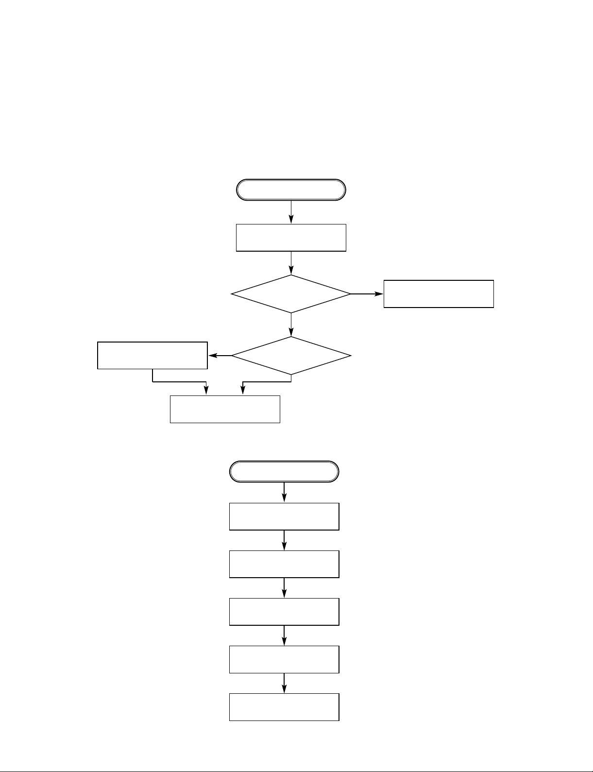
1. µ-COM Circuit
A. Open/Close abnormal
B. Video abnoraml
Check the
connection of P5101.
Check IC501 Pins 13, 14.
YES
NO
NO
YES
YES
(If OK)
YES
Check Front.
Reconnect it.
Refer to SERVO part.
Check the connection of MD.
OPEN/CLOSE ABNORMAL
Check Audio jack.
YES (If OK)
YES (If OK)
YES (If OK)
YES (If OK)
Check PLLFC of MPEG part.
Refer to Audio part.
Refer to MPEG part.
Replace B/D.
AUDIO ABNORMAL
Page 2

- 3-2 -
C. Picture abnoraml
C. Disc Error
Check the disc.
If OK
YES (If OK)
YES (If OK)
Refer to Servo part
Check PLLIC of MPEG part
Check DSP
Check MPEG
YES (If OK)
Replace B/D
PICTURE ABNORMAL
Check Disc
YES (If OK)
YES (If OK)
Refer to Servo part
Replace B/D
DISC ERROR
Page 3
- 3-3 -
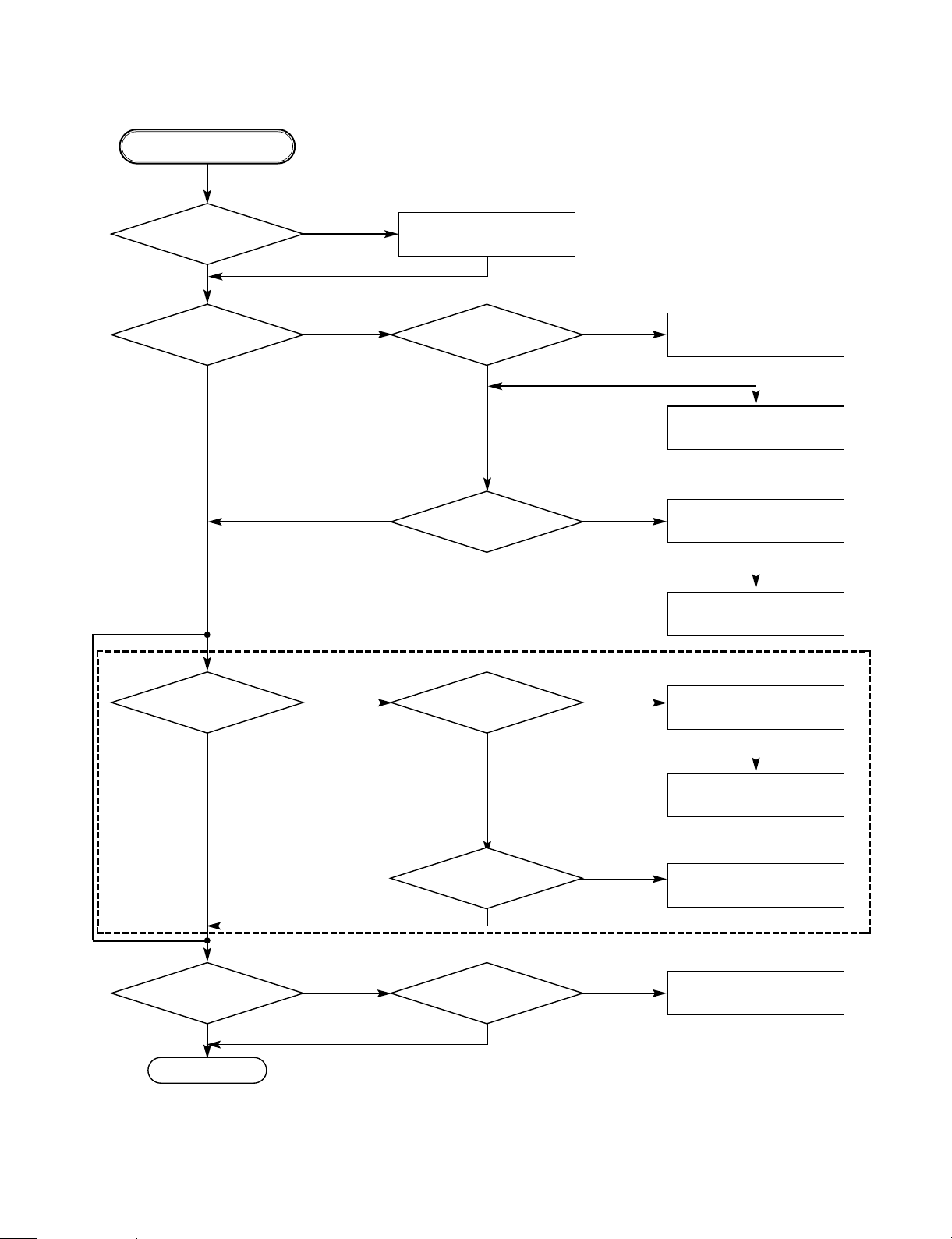
2. MPEG Circuit
Power is on
Does LG Logo appear
on the screen?
Does the
moving picture of the DVD Disc
play on the screen
normally?
Is MPEG data signal normal?
Is error signal normal?
Is MPEG data signal normal?
Is Clock normal?
Does the audio
sound output from MPEG
decoder?
Does the
moving picture of the video
CD play on the screen
normally?
Does the audio sound
output normally?
END
Check power & clock.
Check CD/DVD DSPoutput
signal.
Check MPEG Decoder input
signal.
Check CD/DVD DSPoutput
signal.
Check MPEG Decoder input
signal.
Check CD/DVD DSPoutput
signal.
Check MPEG Decoder input
signal.
Check clock signal
Check clock signal
YES
YES
YES
YES
YES
YES
YES
YES
YES
YES
NO
NO
NO
OK
OK
OK
OK
NO
NO
NO
NO
NO
*OPTION
_ If included VCD function.
Page 4

- 3-4 -
3. RF/Servo Circuit
A.
Does signal pulse
input to IC201 Pins 58, 59 when
the powe is on?
Does signal goes
"High" to IC201 Pin194 when the
power is on?
Does
TTL
pulse output to
IC201 Pins 140, 142?
Does
33.8688MHz clock input
to IC201 Pin 63?
Is IC201
Pins 83, 84, 88, 89 voltage
about 2.2V?
Replace IC201
(IC206 soldering or IC defect).
Check power circuit.
Check "2. -COM Part".
Replace X301 or IC304
(30MHz clock defect)
CHECK POINT(General)
END
NO
NO
NO NO
NO
YES
YES
YESYES
YES
Page 5

- 3-5 -
B
Does tray open or close?
Does the pick-up
slide inner or outer
track?
Fig.1. SLED Driver waveform
Fig.2. Focus Driver waveform
Does
the voltage change
at PMD04 Pins 1, 2 more than
2V on the basis of
3.8V?
Pressing
the open/close key
repeatedly , check the voltage of IC2M1
Pins 13, 14 change
0V to 5V
Does
PMD03 Pin 7 change
high to low?
Does
the pick-up lens move up
and down?
Check Focus Driver output.
(IC201 Pin 83, IC2M1 Pins 37, 38)
Check SLED Driver output.
IC201 Pin 88 IC2M1 Pins 28, 29.
IC201 Pin 88 no output : IC201 is defective
IC2M1 Pin 18 no output : IC2M1 is defective
IC201 Pin 83 no output : IC201 is defective
IC2M1 Pins 1, 2 no output : IC2M1 is defectiv
DECK assembly is defective.
Slide the pick-up to
inner track.
Power on
Check loading Part.
Push Pick-up to inner track to
the end by hand.
DECK assembly is defective.
(Limit sw)
check -COM Part.
Replace IC2M1.
No disc
END
NO
NO
NO
NO
NO
NO
YES
YES
YES
YES
YES
YES
Page 6

- 3-6 -
C.
FOCUS ON?
Check
the focus error moving the
lens up and down.
(IC2A1 Pin 42)
Does the
TTL
level change at IC201
Pin 78 and 132 moving
the lens?
Does the disc turn?
IC201 Pin169 is "High"?
Is OK the track jump.
Does the signal
pulse appear at IC2A1 Pins
39, 29?
Does the screen appear?
OPEN/CLOSE
Replace -COM or IC201.
Replace IC201.
Check IC2A1 Pin 11,12,13,14
in DVD Mode
Fig.3. FOCUS ERROR waveform
IC201 no output : Pick-up is defective.
Check IC201 and IC2M1 when PMD03 Pin 6 is abnormal
Check IC2M1 Pin 21, PMD03
Pin 6 turn when the IC2M1
Pin 21 is less than 2.2V
.
Check A
V
ideo Part is defective.
Check "5.MPEG Circuit."
Check "7.OSD/Video Circuit."
Replace -COM part.
IC2A1 is defective.
DISC IN
END
NO
NO
NO
NO NO
NO
NO
NO
YES
YES
YES
YES
YES
YES YES
YES
Page 7

- 3-7 -
D.
Is the eye-pattern vivid?
Does the
sawtooth waveform emit
at IC2A1 Pin 41?
Does the 1.6V emit?
Check RF Eye-Pattern.
RF : 1.5-1.6V(IC2A1 Pin 57)
Fig.5. RF
waveform
Check IC2A1 Pins 5, 6, 7, 8.
No signal: Pick-up is defective
Replace IC201.
Check IC201 Pin84.
No signal at IC201 : IC201 is defective
¥
Check IC201 Pin 162.
¥
Check the clock at the IC201 Pins 28, 30.
¥ Both are normal : IC201 is defective
Replace IC2A1.
CHECK A
END
NO
NO NO NO
YES
YES YES YES
 Loading...