

Page 1

- 1-1 -
CONTENTS
SECTION 1. GENERAL
• SERVICING PRECAUTIONS
.....................................................................................................................
1-2
• ESD PRECAUTIONS
..................................................................................................................................
1-4
• SPECIFICATIONS
......................................................................................................................................
1-5
• IDENTIFICATION OF CONTROLS
.............................................................................................................
1-6
SECTION 2. AUDIO PART
• ADJUSTMENTS
..........................................................................................................................................
2-1
• INTERNAL BLOCK DIAGRAM OF IC’s
......................................................................................................
2-3
• BLOCK DIAGRAM
......................................................................................................................................
2-9
• SCHEMATIC DIAGRAMS
.........................................................................................................................
2-11
• PRINTED CIRCUIT DIARGAMS
...............................................................................................................
2-21
SECTION 3. DVD PART
• ELECTRICAL TROUBLESHOOTING GUIDE
...........................................................................................
3-1
• BLOCK DIAGRAMS
...................................................................................................................................
3-10
• SCHEMATIC DIAGRAMS
..........................................................................................................................
3-13
• WAVEFORMS
............................................................................................................................................
3-23
• PRINTED CIRCUIT DIAGRAM
..................................................................................................................
3-25
SECTION 4. EXPLODED VIEWS
...................................................................................................
4-1
SECTION 5. SPEAKER PART
........................................................................................................
5-1
SECTION 6. REPLACEMENT PARTS LIST
..................................................................................
6-1
Page 2
SECTION 1. GENERAL PART
SERVICING PRECAUTIONS
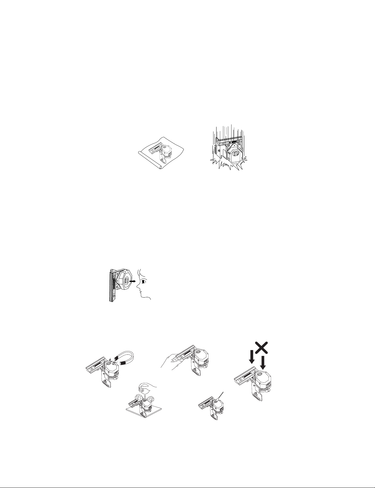
NOTES REGARDING HANDLING OF THE PICK-UP
1. Notes for transport and storage
1) The pick-up should always be left in its conductive bag until immediately prior to use.
2) The pick-up should never be subjected to external pressure or impact.
2. Repair notes
1) The pick-up incorporates a strong magnet, and so should never be brought close to magnetic materials.
2) The pick-up should always be handled correctly and carefully, taking care to avoid external pressure and
impact. If it is subjected to strong pressure or impact, the result may be an operational malfunction and/or
damage to the printed-circuit board.
3) Each and every pick-up is already individually adjusted to a high degree of precision, and for that reason
the adjustment point and installation screws should absolutely never be touched.
4) Laser beams may damage the eyes!
Absolutely never permit laser beams to enter the eyes!
Also NEVER switch ON the power to the laser output part (lens, etc.) of the pick-up if it is damaged.
5) Cleaning the lens surface
If there is dust on the lens surface, the dust should be cleaned away by using an air bush (such as used
for camera lens). The lens is held by a delicate spring. When cleaning the lens surface, therefore, a
cotton swab should be used, taking care not to distort this.
6) Never attempt to disassemble the pick-up.
Spring by excess pressure. If the lens is extremely dirty, apply isopropyl alcohol to the cotton swab. (Do
not use any other liquid cleaners, because they will damage the lens.) Take care not to use too much of
this alcohol on the swab, and do not allow the alcohol to get inside the pick-up.
- 1-2 -
Storage in conductive bag
Drop impact
NEVER look directly at the laser beam, and don’t let
contact fingers or other exposed skin.
Magnet
How to hold the pick-up
aPressure
Pressure
Cotton swab
Conductive Sheet
Page 3
NOTES REGARDING COMPACT DISC PLAYER REPAIRS
1. Preparations
1) Compact disc players incorporate a great many ICs as well as the pick-up (laser diode). These
components are sensitive to, and easily affected by, static electricity. If such static electricity is high
voltage, components can be damaged, and for that reason components should be handled with care.
2) The pick-up is composed of many optical components and other high-precision components. Care must
be taken, therefore, to avoid repair or storage where the temperature of humidity is high, where strong
magnetism is present, or where there is excessive dust.
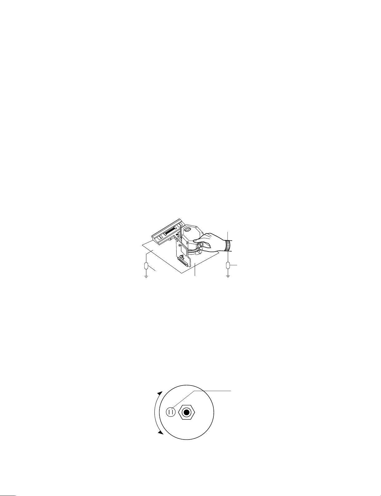
2. Notes for repair
1) Before replacing a component part, first disconnect the power supply lead wire from the unit
2) All equipment, measuring instruments and tools must be grounded.
3) The workbench should be covered with a conductive sheet and grounded.
When removing the laser pick-up from its conductive bag, do not place the pick-up on the bag. (This is
because there is the possibility of damage by static electricity.)
4) To prevent AC leakage, the metal part of the soldering iron should be grounded.
5) Workers should be grounded by an armband (1MΩ)
6) Care should be taken not to permit the laser pick-up to come in contact with clothing, in order to prevent
static electricity changes in the clothing to escape from the armband.
7) The laser beam from the pick-up should NEVER be directly facing the eyes or bare skin.
CLEARING MALFUNCTION
You can reset your unit to initial status if malfunction occur(button malfunction, display, etc.).
Using a pointed good conductor(such as driver), simply short the RESET jump wire on the inside of the
volume knob for more than 3 seconds.
If you reset your unit, you must reenter all its settings(stations, clock, timer)
NOTE: 1. To operate the RESET jump wire, pull the volume rotary knob and release it.
2. If you wish to operate the RESET jump wire, it is necessary to unplug the power cord.
- 1-3 -
Armband
Conductive
Sheet
Resistor
(1 Mohm)
Resistor
(1 Mohm)
VOLUME KNOB
UP
DOWN
VOLUME
RESET jump wire
Page 4

ESD PRECAUTIONS
Electrostatically Sensitive Devices (ESD)
Some semiconductor (solid state) devices can be damaged easily by static electricity. Such components
commonly are called Electrostatically Sensitive Devices (ESD). Examples of typical ESD devices are integrated
circuits and some field-effect transistors and semiconductor chip components. The following techniques should
be used to help reduce the incidence of component damage caused by static electricity.
1. Immediately before handling any semiconductor component or semiconductor-equipped assembly, drain off
any electrostatic charge on your body by touching a known earth ground. Alternatively, obtain and wear a
commercially available discharging wrist strap device, which should be removed for potential shock reasons
prior to applying power to the unit under test.
2. After removing an electrical assembly equipped with ESD devices, place the assembly on a conductive
surface such as aluminum foil, to prevent electrostatic charge buildup or exposure of the assembly.
3. Use only a grounded-tip soldering iron to solder or unsolder ESD devices.
4. Use only an anti-static solder removal device. Some solder removal devices not classified as "anti-static" can
generate electrical charges sufficient to damage ESD devices.
5. Do not use freon-propelled chemicals. These can generate electrical charges sufficient to damage ESD
devices.
6. Do not remove a replacement ESD device from its protective package until immediately before you are ready
to install it. (Most replacement ESD devices are packaged with leads electrically shorted together by
conductive foam, aluminum foil or comparable conductive materials).
7. Immediately before removing the protective material from the leads of a replacement ESD device, touch the
protective material to the chassis or circuit assembly into which the device will by installed.
CAUTION : BE SURE NO POWER IS APPLIED TO THE CHASSIS OR CIRCUIT, AND OBSERVE ALL OTHER
SAFETY PRECAUTIONS.
8. Minimize bodily motions when handing unpackaged replacement ESD devices. (Otherwise harmless motion
such as the brushing together of your clothes fabric or the lifting of your foot from a carpeted floor can
generate static electricity sufficient to damage an ESD device).
- 1-4 -
Page 5

- 1-5 -
SPECIFICATIONS
Power supply Refer to the back panel
[General]
Power consumption 150W
Mass 11kg
External dimensions (W X H X D
) 273X 327X 356mm
Laser Semiconductor laser, wavelength 650mm
Frequency response(audio) 40 - 18,000 Hz
[CD/DVD] Signal-to-noise ratio(audio) More than 70dB(1kHz)
Signal-to-noise ratio(vidio) More than 60dB(1kHz)
Dynamic range (audio) More than 70dB
Harmonic distortion(audio) 02%(1kHz)
[Video]
Video output 1.0V (p-p), 75Ω, negative sync., RCA jack
Video output 1.0V (p-p), 75Ω, negative sync., RCA jack
S-video output
(Y) 1.0V (p-p), 75Ω, negative sync., Mini DIN 4-pin
X
1 (C) 0.3V (p-p), 75Ω
Tuning Range 87.5~108.0MHz or 65 ~74 MHz, 87.5 ~108.0MHz
FM
Intermediate Frequency 10.7MHz
Signal to Noise Ratio 61/58dB
Frequency Response 60~10,000Hz
Tuning Range 522~1611KHz or 530 ~1610KHz
AM(MW)
Intermediate Frequency 450MHz
Signal to Noise Ratio 35dB
Frequency Response 100~2,000Hz
output Power Front: 75W + 75W(6Ω 2ch THD 10%)
Centre: 30W(6Ω 1ch THD 10%)
[Amplifler] Rear: 30W + 30W(6Ω 2ch THD 10%)
T.H.D 0.2%
Frequency Response 42~25,000Hz
Signal-to-noise ratio 80dB
Front Speaker(FE-DV55VE)
Satellite Subwoofer(FE-DV55CVE)
Rear Speaker(FE-DV55SE)
Type 3Way 3Speaker 1Way 1Speaker 1Way 1Speaker
Impedacne 6Ω 6Ω 6Ω
Frequency Response 60 ~20,000Hz 100~20,000Hz 120~20,000Hz
[Speakers] Sound Pressure Level 86dB/W(1m) 84dB/W(1m) 84dB/W(1m)
Rated Input Power 75W 30W 30W
Max. Input Power 150W 30W 60W
Net Dimensions(W X HX D)
230 X 326 X 277mm 200 X 90 X 106mm 90 X 125 X 106mm
Net Weight 5.07kg 0.8kg 0.59kg
Tape Speed 3KHz ± 50Hz
Wow Flutter 0.25%(MTT-111, JIS-WTD)
F.F/REW Time 120sec(C-60)
[TAPE] Frequency Response 125~8,000Hz
Signal to Noise Ratio 43dB
Channel Separation 45dB(P/B)/42dB(R/P)
Erase Ratio 52dB(MTT-5511)
[Supplied
Accessories]
• Audio cable ......................................................................................................................................... 1
• Speakers............................................................................................................................................. 5
•
Remote control.................................................................................................................................... 1
• AM Ioop antenna................................................................................................................................. 1
• Video cable ......................................................................................................................................... 1
• Speaker cables ................................................................................................................................... 3
• Batteries.............................................................................................................................................. 2
• FM antenna......................................................................................................................................... 1
[TURE]
*DESIGN and specifications are subject to change without notice.
Page 6

- 1-6 -
IDENTIFICATION OF CONTROLS
FRONT PANEL
1
2
3
4
5
6
7
8
9
10
11
12
13
14
15
16
19
21
22
20
23
24
25
26
27
28
29
30
31
33
32
18
17
1. CD DOOR
2. FUNCTION SELECT BUTTON
(TUNER/BAND, DVD/CD, TAPE, AUX)
3. DISC SKIP BUTTON
4. DISC DIRECT PLAY(1-3)BUTTON
5. • PRESET (+)/(-) BUTTONS(RADIO)
• AUTO TUNING (+)/(-) BUTTONS(RADIO)
• SKIP/SEARCH(
)
BUTTONS(DVD/CD)
• REWIND/FAST FORWARD BUTTONS(TAPE)
• (
= TAPE PLAY DIRECTION BUTTONS
(
: OPTIONAL)
• CD PLAY BUTTON( )
• STOP/RESET BUTTON( )
6. UP( )BUTTON
7. MULTI JOG DIAL
8. STANDBY/ON BUTTON
9. SET/PAUSE/STEP/TAPE COUNTER/RDS
BUTTON(OPTIONAL)
10. HEADPHONE SOCKET(3.5mm)
11. DOWN( )BUTTON
12. PUSH EJECT POSITION(TAPE A)
13. PAUSE INDICATOR
14. SET UP BUTTON
15. MENU BUTTON
16. ENTER BUTTON(DVD)
17. NORMAL DUBBING/CD SYNCHRO BUTTON
18. HI-SPEED DUBBING BUTTON
19. RECORD/RECORD PAUSE BUTTON(TAPE)
20.
PUSH EJECT POSITION(TAPE B)
21. PALY MODE/DEMO BUTTON(OPTIONAL)
22. EQ PATTERN BUTTTON(OPTIONAL)
23. MODE/RIF BUTTON
24. MDSS BUTTON
25. REPEAT BUTTON
26. PROGRAM/MEMORY BUTTON
27. VOLUME
28. TIMER BUTTON
29. CD DOOR OPEN/CLOSE( )BUTTON
30. CLOCK BUTTON
31. REMOTE SENSOR
32. POWER INDICATOR
33. DISPLAY
Page 7

- 1-7 -
REAR PANEL
DISPLAY WINDOWS
43215
6
7
8
9
10
BA
2
1
3
MP3
MDSS CHP/TRK ST
REC PROG. RDS MHz kHz.
ANGLE
REPEAT
LS
LR
PROLOGIC
3 STEREO
S
LFE
C
RS
REC HI-SP DUBBING
DISC A-B SYNC.
OVER
TITLE
CD
1 2 3 4 5 6 7 8 9
10 11 12 13 14 15
16
13468111315
2 5 7 9 10 12 14 16 17
1820222426283032
33 31 29 27 25 23 21 19
2
1. VIDEO OUT JACK
2. S-VIDEO OUT JACK
3. VIDEO SELECTOR SWITCH*
4. OPTICAL OUT JACK
5. ANTENNA TERMINAL
6. AUXILIARY INPUT SOCKETS
7. CENTRE SPEAKER CONNECTOR
8. SUB WOOFER OUT CONNECTOR
9. SPEAKER CONNECTORS
10. POWER CORD
1. MDSS indicator
2. LEVEL indicator
3. TIMER indicator
4. MP3 indicator
5. CHPATER/TRACK indicator
6. LEFT FRONT SPEAKER indicator
7. DOLBY 3 STEREO indicator
8. PROGRAM indicator
9. DOLBY PROLOGIC indicator
10. CENTRE SPEAKER indicator
11. RDS indicator(OPTIONAL)
12. RIGHT FRONT SPEAKER indicator
13. DISC REPEAT PLAY indicator
14. FM STEREO RECEIVING
indicator
15. FM STEREO indicator
16. CD MUSIC CALENDAR OVER
indicator
17. MUTE indicator
18. TAPE B ENTERED/DIRECTION
indicator
19. SYNCHRO RECORDING indicator
20. PLAY MODE indicator(OPTIONAL)
21. A-B REPEAT indicator
22. TAPE A ENTERED/DIRECTION
indicator(OPTIONAL)
23. TAPE DUBBING indicator
24. RECORD indicator
25. LFE(Low Frequency Effect)
indicator
26. RIGHT SURROUND SPEAKER
indicator
27. SURROUND indicator
28. LEFT SURROUND SPEAKER
indicator
29. ANGLE indicator
30. CD indicator
31. DISC NO. indicator
32. PLAY/PAUSE indicator
33. CD MUSIC CALENDAR indicator
Page 8

- 1-8 -
Remote Control
• you will find instructions for each of the remote control functions in the appropriate sections of this instruction
manual.
*MENU button
Use the MENU button to display the menu screen
included on DVD video discs. To operate a menu
screen.
**Directional arrow buttons
(up, down, left, right) for use in highlighting a selection
on a GUI menu screen, TITLE and MENU screen.
***TITLE button
Use the TITLE button to display the title screen
included on DVD video discs. To operate a menu
screen.
POWER
12345
09876
1
2
3
4
5
6
7
8**
9
10
11***
12
13
14
15
16
29
28
27
26
25
24
23
22
21
20*
19
18
17
TUNER DVD/CD TAPE
SELECT
STEP
STOP
PROGRAM
NEXTPREV.
RANDOMREPEAT
EQ
SELECT/ENTER
SOUND
DISPLAY
SET UP
TITLE
REW
FWD
SUBTITLE
ZOOM
SLOW
SEARCH
MARKER
CLEARA-B
ANGLE
MENU
VOLUME
RETURN
AUDIO
MDSS SLEEP
PRESET
AUX
MUTE
CD
TAPE
DVD
TAPE A TAPE B
D.SKIP
SPECTRUM
1. POWER button
2. NUMERIC button
3. FUNCTION SELECT buttons
4. TAPE A/B SELECT button
5. MDSS button
6. TAPE FUNCTION button
• REWIND/FAST FORWARD PLAY
• FORWARD PLAY
• BACKWARD PLAY(OPTIONAL)
• STOP
• RECORD/RECORD PAUSE
7. EQ PATTERN button
8. ARROW buttons
9. SELECT/ENTER button
10. SUBTITLE button
11. TITLE button
12. ANGLE button
13. ZOOM button
14. REPEAT A-B button
15. CLEAR button
16. SLOW buttons
17. SPECTRUM button
18. VOLUME +/- buttons
19. MARKER/SEARCH buttons
20. MENU button
21. SET UP buttons
22. RETURN button
23. DISPALY button
24. AUDIO button
25. SOUND button
26. DVD/CD CONTROL buttons
• PLAY/SELECT
• PAUSE/STEP
• STOP
• SKIP/PREV.
• SKIP/NEXT
• PROGRAM
• REPEAT
• RANDOM
• DISC SKIP
SKIP
Press and hold button for about two secons
for search function.
27. SLEEP button
28. PRESET( )buttons
29. MUTE button
 Loading...