

Page 1
- 2-3 -
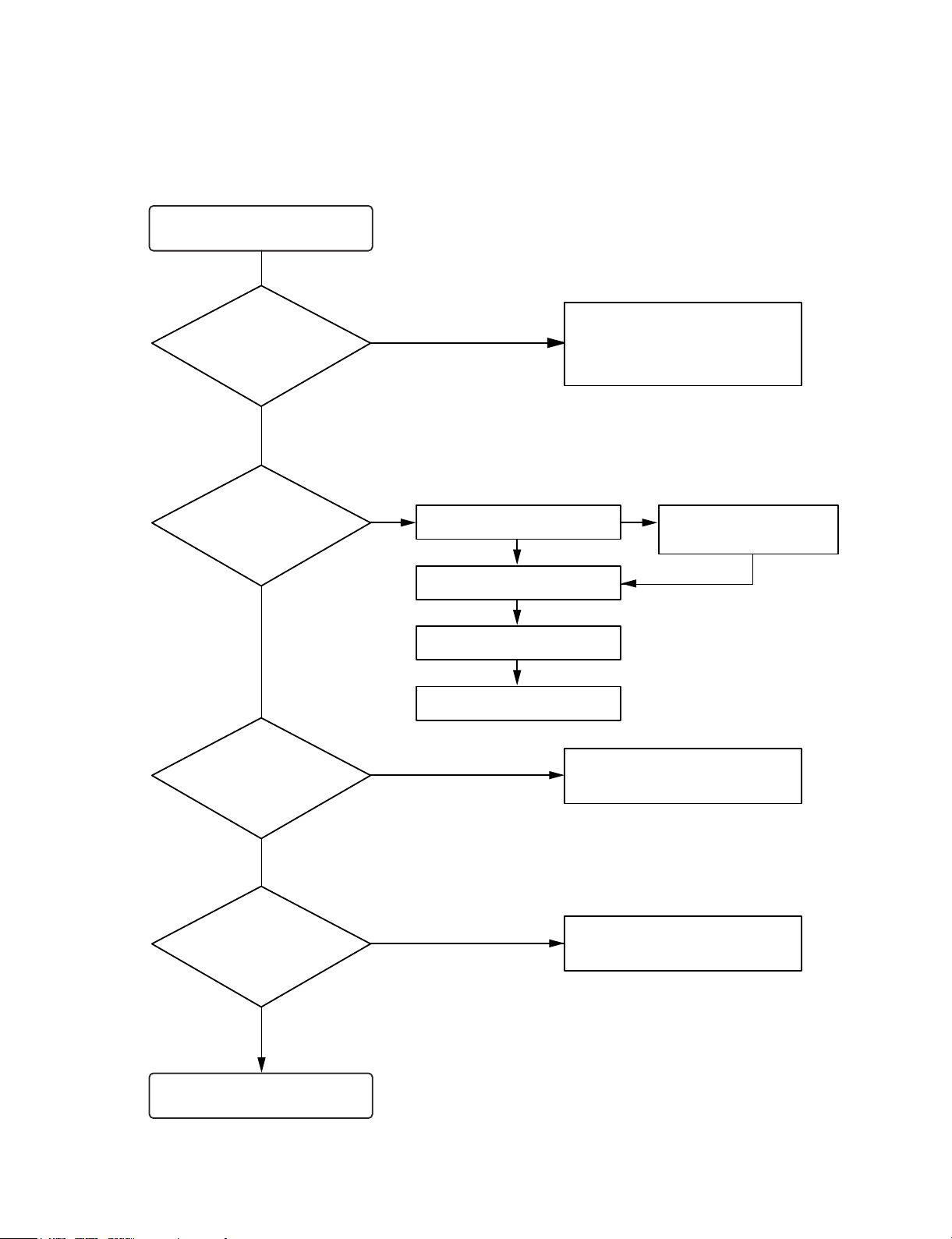
TROUBLESHOOTING
Turn power on.
Is power on?
Does initial read work?
Does it play?
Does it output audio?
Check power supply circuit.
PN807 PIN5, 6.2V
PN807 PIN7, 5V
IC803 PIN 2, 3.3V
Check the connector
PN801, PN802, PN809
Check the tracking servo circuit.
Check the PN807 PIN1, 3
OK
YES
YES
YES
YES
YES
YES
NO
NONO
Check the DISK turns
Check the Laser
Check the focus circuit
Check the TRAKING circuit
NO
NO
Page 2
- 2-4 -
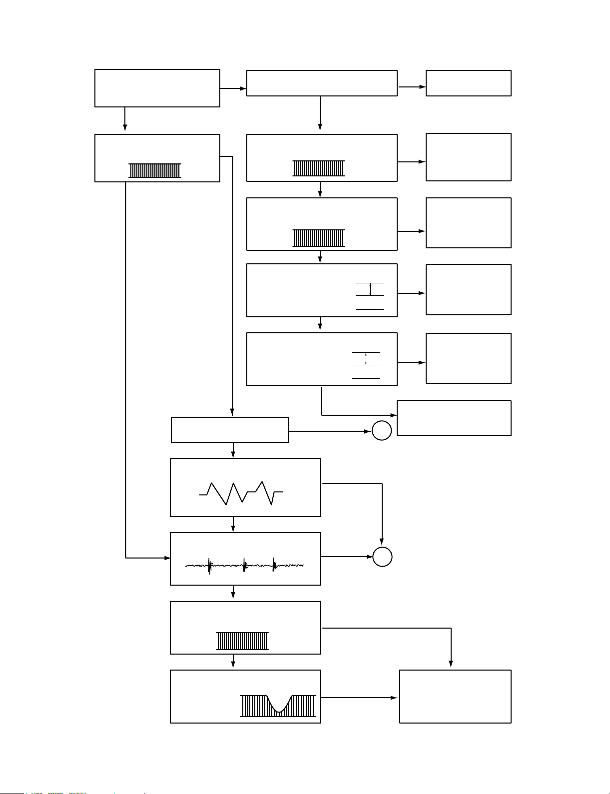
Fails to initial read
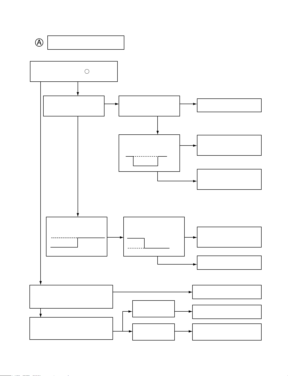
A
B
2V
5V
0V
5V
0V
1V
0V
1.2V
0V
0.8V
NO NO
NO
NO
NO
NO
NO
NO
NO
NO
YES
YES
YES
YES
YES
YES
YES
YES
YES
YES
YES
YES
Disc motor turns
Does RF waveform appear?
IC801 Pin3
Check the Data transmission from
PN809 pin11 to CD DSP
Check the Data transmission from
PN809 pin13 to MICOM
Check the change of SLDO
Voltage(IC801 pin23)
Check the change of SL +,
SL - Voltage
(IC802 pin 18, 19)
Check the Voltage change of PN 809
PIN20(OPEN, CLOSE)
Defective connector
PN809
Defective connector
PN809, Defective
MICOM
Defective connector
PN809, Defective
IC801
Defective IC801
Defective IC802
Defective contact PN802
Defective PICK-UP
Does laser light?
focus coil drive wareform.
TRACKING ERROR wareform
Is rotation normal?
Defective IC801
Defective PICK-UP
Is there no dropout of RF signal?
Does FA+ waveform appear at
IC802 pin13?
Does TE waveform appear at
801 pin 15?
Page 3
- 2-5 -
NO
NO
NO
NO
NO
NO
Laser does not light.
Is “3.5V” applied to pin of IC 801?
Is power supplied to laser Q801?
(Q 801 collector: about 1.8V)
Does laser current flow?
1.0V across R808
Is data transferred from
MICOM IC ?
Does voltage appear at IC
802 pin 17, 18?
Defective MICOM.
Defective MICOM.
Defective connector.
Defective IC 801, 802
Defective slide motor and/or
connector.
Defective LMT SW and/or
connector.
Defective Q 801 and/or laser.
Defective laser and/or
connector.
Did pickup return to
innermost circular?
Does it stop at inner pick
circular after shift?
Is defect output from LM
SW applied to pin 2 of
PN802?
R808»1.0V
R808«1.0V
YES
YES
YES
YES
OPEN
CLOSE
YES
YES
YES
YES
YES
YES
70
Page 4

- 2-6 -
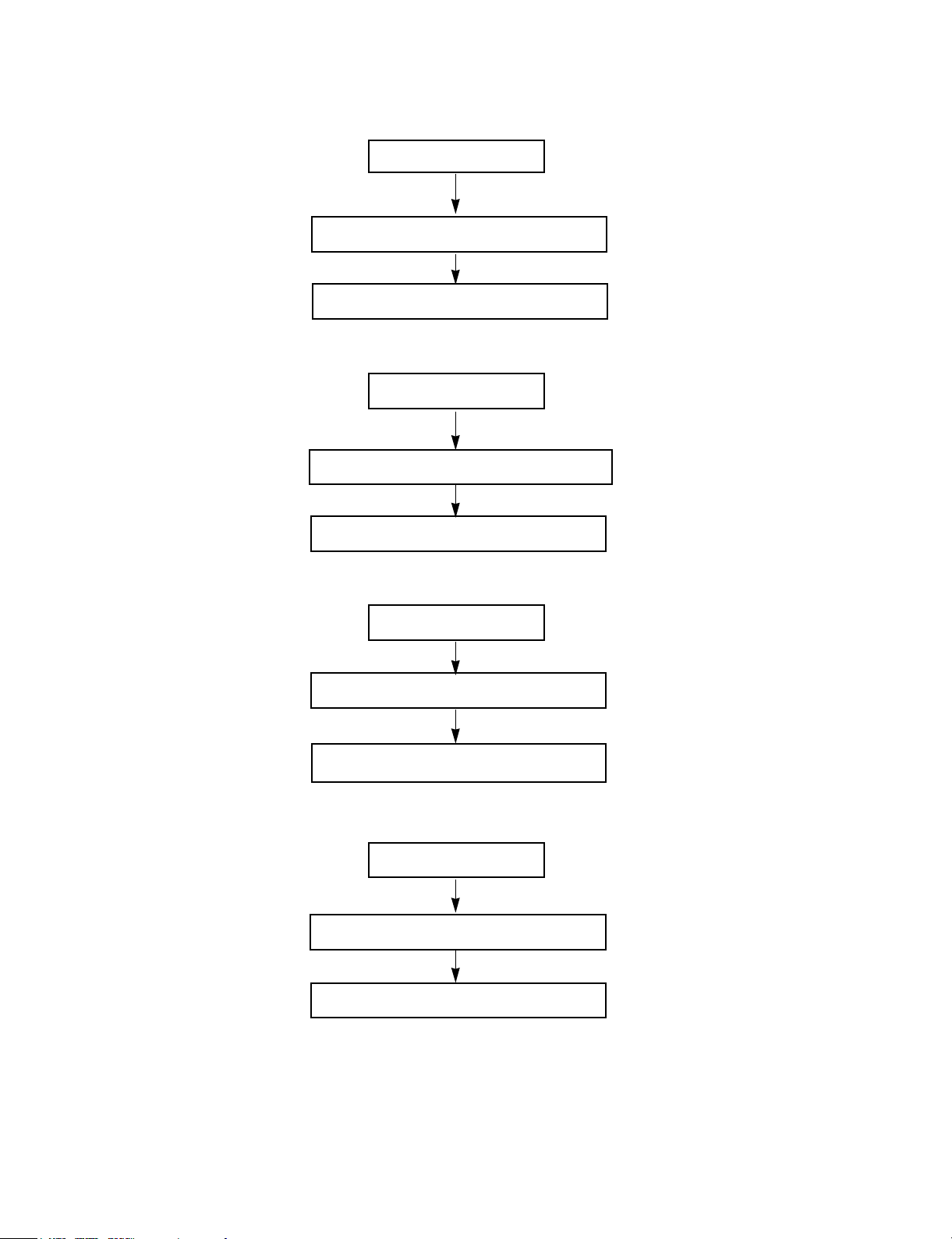
B
NO
NO
NO
NO
NO
YES
YES
YES
YES
Laser lights
Does lens move up/down?
Check the signal of
FOCUS SEARCH
(IC801 Pin 21)
Chekc the signal of PN802
pin 13, 14
Does FE signal appear?
(IC801 pin 13)
Does DRF signal appear? (IC 801 pin67)
Defective IC801
Defective IC802
Open activator and/or connector
Defective IC801
Degraded laser diode
Defective PICK-UP
Page 5

- 2-8 -
VKK PART
Does DC - 33V appear at
PN703 Pin .
OK
Dose -33V appear at
ZD702(-)
Check the Q752
TURN ON
Replace the Q752
Refer to power circuit
END
Check the -33V(LOW)
of C742(-)
Replace the D709,
D710
YES
YES
NO
NO
P-SENS PART
Does +5V appear at ZD701?
Check the pattern of
IC301 Pin .
Check the waveform
of D796(+).
Check the ZD703 or replace
Replace the D796
YES
YES
NO
NO
26
9
Page 6

- 2-9 -
Power Circuit
Muting circuit (MUTE)
Check the Fuse
Check the DC output
of C770(+), C720(-)
Check the DC Input of IC704
Check the DC
output of IC703
Check the DC 12V
Output of IC705
Check the 5V of IC703
pin 2(CD FUNCTION)
END
Dose “High” appear at
Q701, Q751, Q251, Q201 “B”
check the “LOW” Q701, Q751,
Q201, Q251 “C”
Refer to “IC202 Troubleshooting”
(ONLY Q201, Q251)
MUTE
Replace the Fuse
Check the AC Output of
CN701 pin1, 5
Check the AC Output of
CN701 PIN 7, 10
Replace the IC705
Replace the D711
Replace the
D712, D795, D794
Check the D791, D792, D793
Check the “High” of
D796(+)
Check the “High” of D793(+)
Check the “High” of Q702 “E”
(ONLY Q701, Q751)
Replace the TR
Refer the Q702
Refer to “IC301
Troubleshooting”
Replace the IC703
Replace the Transformer
Replace the Transformer
Check the Voltage of
IC301 PIN82
Refer to “IC301
Troubleshoot”
YES
YES
YES
YES
YES
YES
YES
YES
YES
YES
YES
YES
YES
NO
NO
NO
NO
NO
NO
NO
NO
NO
NO
NO
NO
Page 7

- 2-10 -
Audio abnormal
SPK Relay Troubleshooting
Check the output of
IC701 Pin 21, 22
Refer to “IC701
Troubleshooting”
Refer to “Muting
Troubleshooting”
Check the power circuit
Refer to “Spk Relay
troubleshooting”
Refer to “power circuit”
Check “High” of Q745 “B”
Refer to “IC501
Troubleshooting”
Replace the RELAY(RY710)
Replace the Q745
Check the input of
IC601 IC602
Check the Input of IC601,
pin24, 25 IC602 pin 1, 7
Check the RY701
END
Check the 12V of D741(+)
Check the “Low” of Q745 “C”
Check the output
END
YES
YES
YES
YES
YES
YES
YES
YES
NO
NO
NO
NO
NO
NO
NO
NO
Page 8
- 2-11 -
FUNCTION MODE Audio abnormal
TAPE
Check the signal input of IC601 pin 28, 37
Refer to “IC202 Troubleshooting”
AUX
Chekc the signal input of IC601, pin 29, 36
Check the signal input of JK601
Check the signal input of IC601 pin 31, 34
Refer to “CD Troubleshooting”
Check the signal input of IC601 pin 30, 35
Refer to “IC102 Troubleshooting”
CD
Tuner
Page 9

- 2-12 -
Refer to “IC301
Troubleshooting”
IC301 Troubleshooting
IC501, IC302 Troubleshooting
Check the power supplying IC301 Pin 17, 46, 90?
Refer to “Power Circuit Troubleshooting”
Check the P-SENS
Replace the X301
Check the RESET circuit
Refer to “Power Circuit Troubleshooting”
Check the Data of IC301 Pin 3, 4, 5
(CD ➞ TAPE FUNCTION)
Replace the
IC501/IC302
Check the pattern
of (IC301, IC501, IC302)
Check the 5v of IC301 pin26
Check the oscillation of X301
When power supplying to IC301 pin17.
(Low ➞ High)
Replace the IC301
Check the power supplying to IC501/IC302 pin 16
Check the CLK Data of IC501/IC302 pin 2, 3
Check the CONTROLL function
END
YES
YES
YES
YES
YES
YES
YES
NO
NO
NO
NO
NO
NO
NO
Page 10

- 2-13 -
IC601 Troubleshooting
Check the 9V of ZD601
Refer to “FUNC Troubleshooting”
Replace the ZD601
Refer to “SPK Relay”
Check the FUNC CLOCK DATA of pin 21, 22
Check the power of pin 39
Check the signal input
Check the Signal output of pin25, 24
OK
YES
YES
YES
YES
NO
NO
NO
FM (TUN101)
Check the 12V input of TUN101 B+ 6
Check the “High” Voltage of TUN101 VT 5
Check the OSC waveform of TUN101 Pin 8
Refer to “IC102 Troubleshooting”
Check the 12V of Q102 “E”
Refer to “Power
Circuit Trouble-
shooting”
Check the “GND” of IC103 Pin 7
Refer to “IC103
Troubleshooting”
Replace the Q102
Replace the TUN101
Replace the TUN101
YES
YES
YES
YES
YES
NO
NO
Page 11

- 2-14 -
IC102 Troubleshooting
Is power supplied to pin8
Check the waveform of Pin 20, 21
Check the output of Pin 16, 17
END
Refer to “Power Circuit
Troubleshooting”
Check the FM(TUN101) & AM(L107)
Replace the IC102
Replace the IC102
Check the “Low” of Pin 13
Refer to “IC103
Troubleshooting”
YES
YES
YES
YES
NO
NO
NO
NO
NO
IC103 Troubleshooting
Check the power supplying to pin 17
Check the oscillation of X104
Check the waveform of CE, DI, DO, CLK
Is the normal ?
END
Refer to “Power Circuit
Troubleshooting”
Replace the X104
Check the line orrefer to “IC 301
Troubleshooting”
CE: Chip Enable
DI: Data Input(from u-com)
DO: Data Output(to u-com)
CLK: Tuner mode clock
Replace the IC103
YES
YES
YES
YES
NO
NO
NO
NO
Page 12

- 2-15 -
AM•COIL Troubleshooting
Check the “High” of L107 Pin 2
Refer to “IC103 Troubleshooting”
Replace the L107
Check the oscillation of L107 Pin 13
Refer to “IC102 Troubleshooting”
YES
YES
NO
NO
Play
Check the VCC supplying to IC202 pin 18
Refer to “Power Circuit Troubleshooting”
Check the Deck Mecha
Replace the Deck
Mecha.
Replace the IC202
Check the signal output of IC202 pin 5, 20
Check the Muting Circuit
YES
YES
YES
NO
NO
NO
YES
YES
NO
Dubbing(“NORMAL or REC “//“HIGH”)
Q252, 202 “OFF”//“ON” : R273, 223
“LOW”//“HIGH
Q253, 203 “ON”//“OFF” : R225, 275
“High”//”Low”
Refer to “IC203 Troubleshooting”
Refer to “REC Troubleshooting”
Page 13

- 2-16 -
REC (Q252, Q202 ON / R273, R223 High)
Check signal supplied to IC202 pin 11, 14?
Check the output of IC202 Pin9, 16
Check the IC201 pin6 : 12V and pin 4 : High
Check the power or Refer to “IC203
Troubleshooting”
Check the power
supplying to C236(+)
Check the 0.6V of Q208
“B”
Check the “Low” of
Q208 “C”
Replace the Q207
END
Check the Vcc power of IC202 Pin18
Check the oscillation of L203 pin 2, 3
Replace the DECK
Check the “Low” of Q253,
Q203 “B”
Replace the Q253, Q203
Refer to “IC203
Troubleshooting”
Refer to “Power Circuit
Troubleshooting”
Refer to “IC203
trouleshooting”
Replace the Q208
Replace the L203
YES
YES
YES
YES
YES
YES
YES
YES
YES
NO
NO
NO
NO
NO
NO
NO
NO
NO
 Loading...