

Page 1
- 8 -
TAPE DECK ADJUSTMENT
1. AZIMUTH ADJUSTMENT
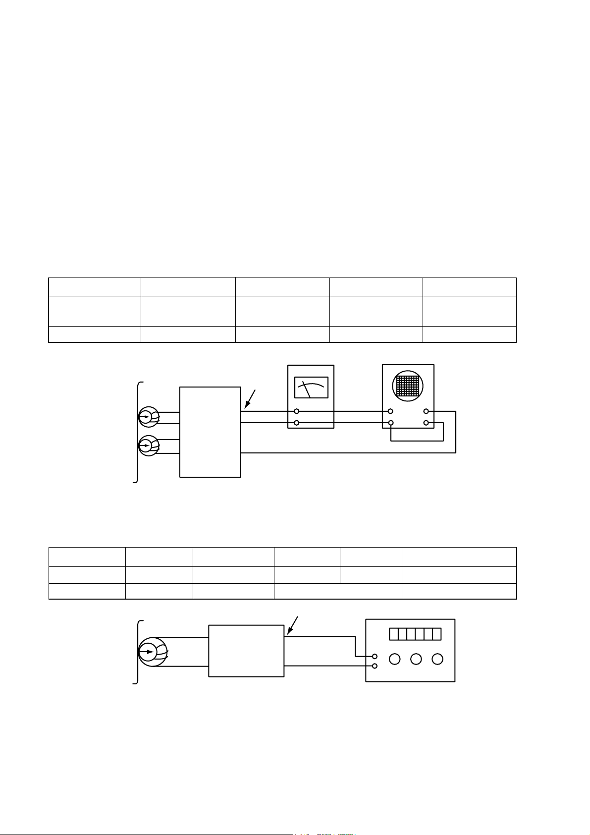
Figure 1. Azimuth Adjustment Connection Diagram
CH1 CH2
Speaker Out
Playback Mode
Head
Test Tape
MTT-114
L ch
R ch
GND
Dual-trace
synchroscope
Electronic
Voltmeter
L out
R out
Unit
ADJUSTMENTS
This set has been aligned at the factory and normally will not require further adjustment. As a result, it is not
recommended that any attempt is made to modificate any circuit. If any parts are replaced or if anyone tampers
with the adjustment, realignment may be necessary.
IMPORTANT
1. Check Power-source voltage.
2. Set the function switch to band being aligned.
3. Turn volume control to minimum unless otherwise noted.
4. Connect low side of signal source and output indicator to chassis ground unless otherwise specified.
5. Keep the signal input as low as possible to avoid AGC and AC action.
Deck Mode Test Tape Test Point Adjustment Adjust for
A Deck Playback MTT-114 Speaker Out
DECK Screw
Maximum
Azimuth Screw
B Deck Playback MTT-114 Speaker Out Azimuth Screw Maximum
2. MOTOR SPEED ADJUSTMENT
Figure 2. Motor Speed Adjustment Connection Diagram
Head
Playback Mode
Unit
Speaker Out
GND
L out
R out
Record/Playback
head
Test Tape
MTT-111
Frequency Counter
Deck Mode Test Tape Test Point Adjustment Adjust for Remark
Normal Speed MTT-111 Speaker Out VR201 3kHz ± 1% A Deck
HI-Speed MTT-111 Speaker Out more than 5.4kHz HI-Speed Dubbing Mode
Page 2
- 9 -
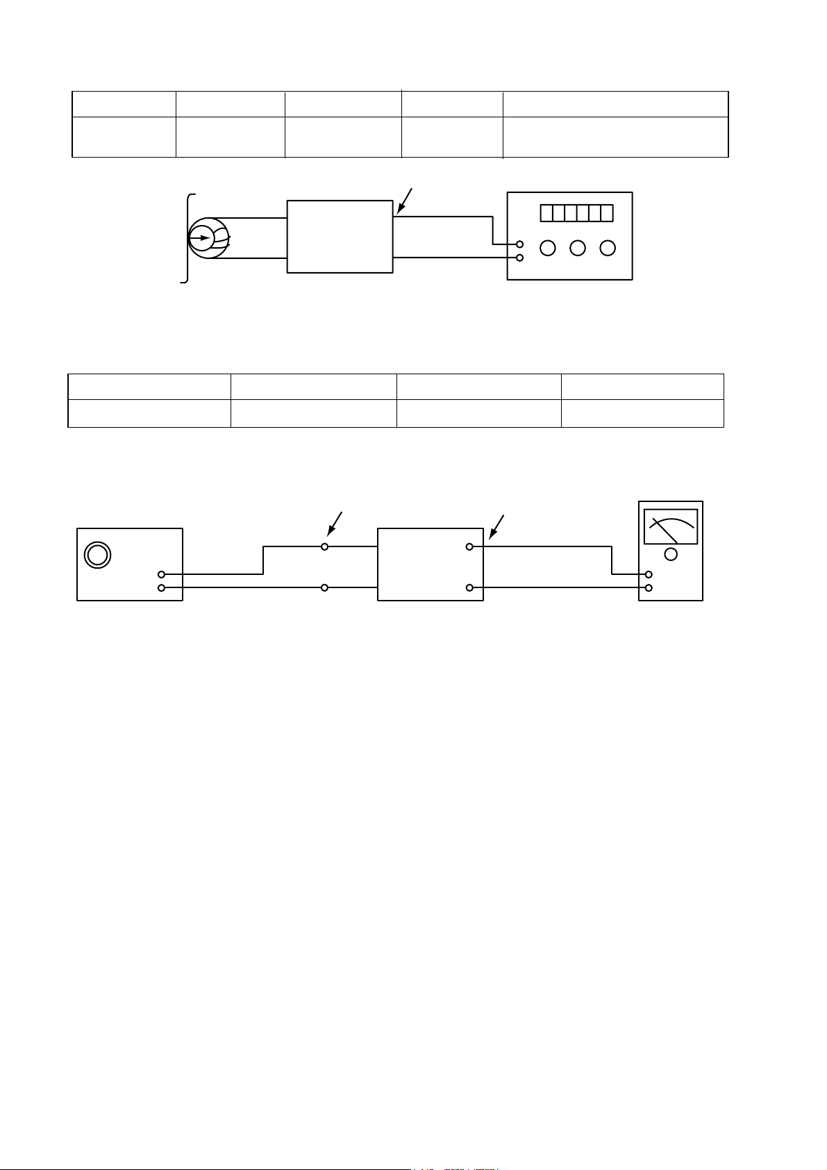
3. RECORD BIAS ADJUSTMENT
Head
Unit
PN202
GND
Record/Playback
head
Test Tape
MTT-5511
Record/Playback
and Pause Mode
Frequency Counter
Deck Mode Test Tape Test Point Adjustment Adjust for
Rec/Pause MTT-5511
ERASE HEAD
L203
60kHz±5kHz (Auto-stop)
WIRE(PN202) 85kHz±5kHz (Auto-Reverse)
Figure 3. Record Bias Adjustment Connection Diagram
4. TUNER ADJUSTMENT
Figure 4. Tuner(S curve) Adjustment Connection Diagram
Unit
Signal Generator
GND
Electronic
OSCILLOSCOPE
FM Antenna
Terminal
Speake
Item Test Point Adjustment Adjust for
DC Voltage Checker Pin L106 0V
±50mV
 Loading...