

Page 1

- 8 -
CH1 CH2
Speaker Out
Playback Mode
Head
Test Tape
MTT-114
L ch
R ch
GND
Dual-trace
synchroscope
Electronic
Voltmeter
L out
R out
Unit
This set has been aligned at the factory and normally will not require further adjustment. As a result, it is not
recommended that any attempt is made to modificate any circuit. If any parts are replaced or if anyone tampers
with the adjustment, realignment may be necessary.
IMPORTANT
1. Check Power-source voltage.
2. Set the function switch to band being aligned.
3. Turn volume control to minimum unless otherwise noted.
4. Connect low side of signal source and output indicator to chassis ground unless otherwise specified.
5. Keep the signal input as low as possible to avoid AGC and AC action.
ADJUSTMENTS
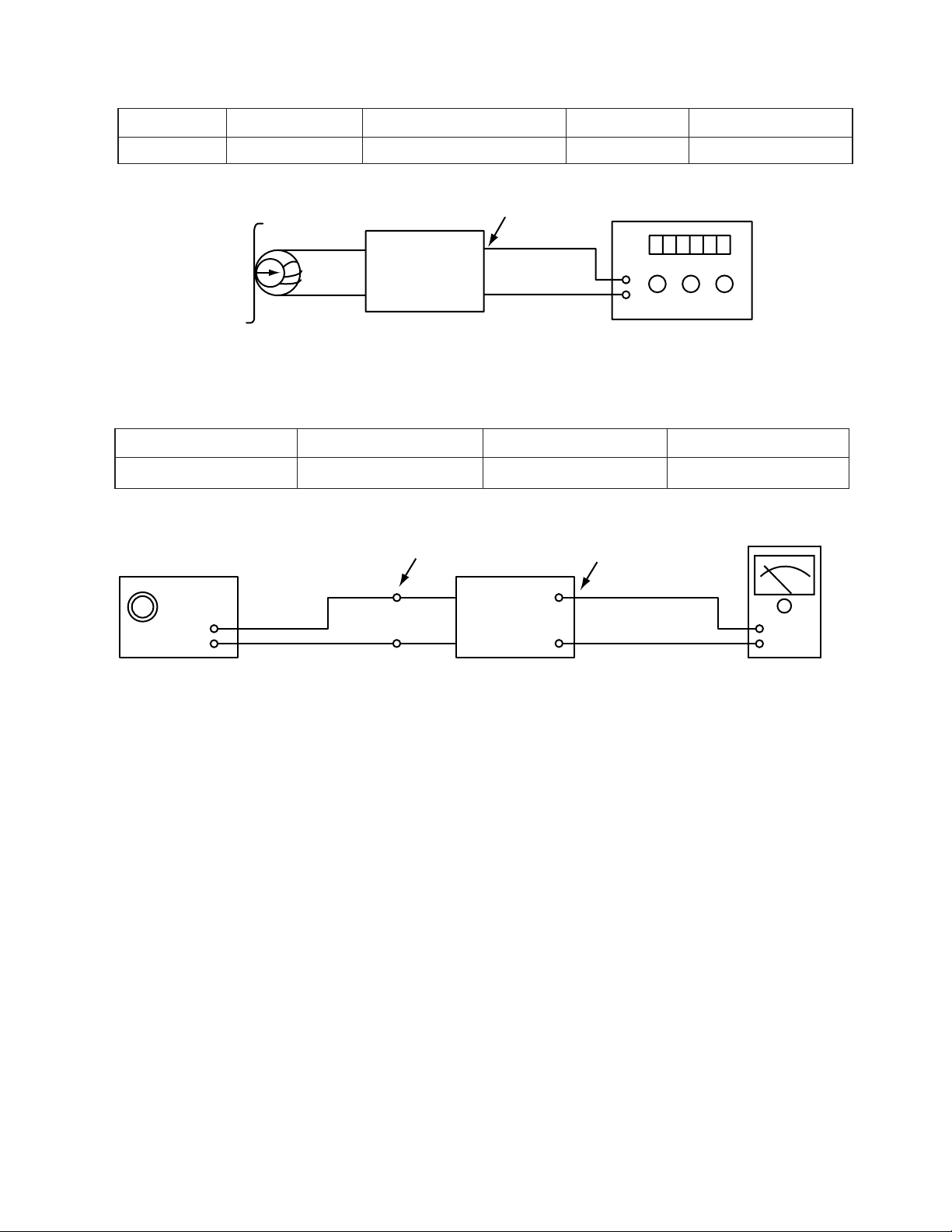
Deck Mode Test Tape Test Point Adjustment Adjust for
A Deck Playback MTT-114 Speaker Out DECK Screw Maximum
B Deck Playback MTT-114 Speaker Out Azimuth Screw Maximum
2. MOTOR SPEED ADJUSTMENT
Figure 1. Azimuth Adjustment Connection Diagram
Figure 2. Motor Speed Adjustment Connection Diagram
Head
Playback Mode
Unit
Speaker Out
GND
L out
R out
Record/Playback
head
Test Tape
MTT-111
Frequency Counter
Deck Mode Test Tape Test Point Adjustment Adjust for Remark
Normal Speed MTT-111 Speaker Out VR201 3kHz ± 1%
Hi-Speed MTT-111 Speaker Out more than 5.4kHz High-Speed Dubbing Mode
TAPE DECK ADJUSTMENT
1. AZIMUTH ADJUSTMENT
Page 2
- 9 -
3. RECORD BIAS ADJUSTMENT
Head
Unit
PN202
GND
Record/Playback
head
Test Tape
MTT-5511
Record/Playback
and Pause Mode
Frequency Counter
Deck Mode Test Tape Test Point Adjustment Adjust for
Rec/Pause MTT-5511 ERASE HEAD Wire(PN202) L203 90kHz±5kHz
Figure 3. Record Bias Adjustment Connection Diagram
Figure 4. Tuner(S curve) Adjustment Connection Diagram
4. TUNER ADJUSTMENT
Unit
Signal Generator
GND
Electronic
OSCILLOSCOPE
FM Antenna
Terminal
Speake
Item Test Point Adjustment Adjust for
DC Voltage Checker Pin TP1, TP2 L106 0V±50mV
Page 3
- 10 -
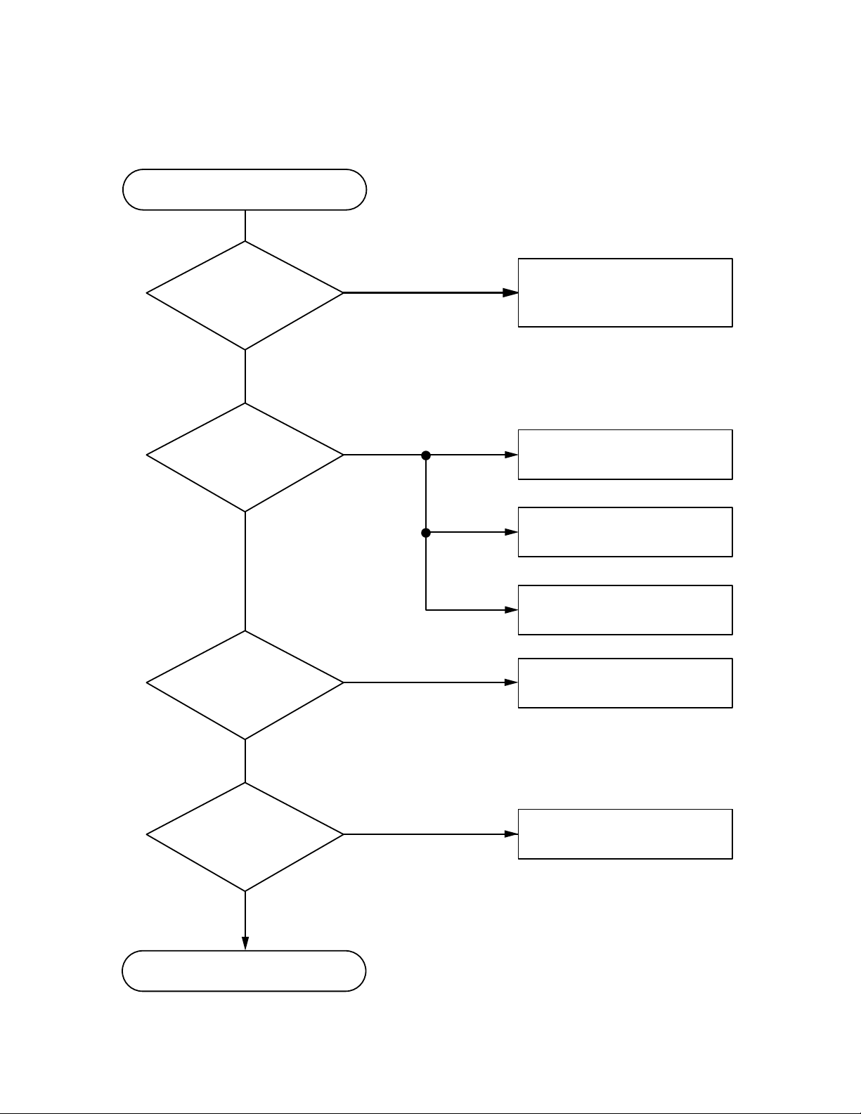
TROUBLESHOOTING
Turn power on.
Is power on?
Does initial read work?
Does it play?
Does it output audio?
Check power supply circuit.
(Check PN 701)
Check laser circuit.
Check focus circuit.
Check disc.
Check tracking servo circuit.
Check audio circuit.
OK
YES
YES
YES
YES
NO
NO
NO
NO
Page 4

- 11 -
Fails to initial read
1.3V
A
B
YES
YES
YES
YES
YES
YES
YES
YES
NO
NO
NO NO NONO
NO
NO
NO
NO
Does laser light?
Disc motor turns.
Does RF
waveform
appear?
TP 801(RF)
Does tracking
servo work?
Lower envelope
of TP801(RF)
waveform is flat.
Does signal
appear at
TP801(TEO)?
Does signal appear at IC 803
Pin and Pin ?
Does GFS (IC802 pin )
show as below?
Is rotation normal?
Is there no dropout of RF
signal?
Does TE2 signal
appear at pin
of IC801?
Defective IC
801, pick up
and/or open
wire.
Detective pattern.
Defective IC 801
and/or IC 803
Defective pick-up
and/or connector.
Defective IC 801.
Scratch in disc
initial read area.
Defective pick-up
adjustment focus offset.
53
26
27
Page 5

- 12 -
A
NO
NO
NO
NO
NO
NO
Laser does not light.
Is “3.5V” applied to pin of IC 801?
Is power supplied to laser Q801?
(Q 801 collector: about 1.8V)
Does laser current flow?
1.0V across R801
Is data transferred from
MICOM IC ?
Does voltage appear at IC
803 pin ⑪, ⑫?
Defective MICOM.
Defective MICOM.
Defective connector.
Defective IC 801, 803
Defective slide motor and/or
connector.
Defective LMT SW and/or
connector.
Defective Q 801 and/or laser.
Defective laser and/or
connector.
Did pickup return to
innermost circular?
Does it stop at inner pick
circular after shift?
Is defect output from LM
SW applied to pin ② of
PN803?
R801≫1.0V
R801≪1.0V
YES
YES
YES
YES
OPEN
CLOSE
YES
YES
YES
YES
YES
YES
70
Page 6

- 13 -
B
C
Does lens move up/down?
Does IC 801 out focus
search signal?
IC 801 pin (FEO)
Is focus search signal
applied to pin , of
CN801?
Laser lights.
Confirm
initial
read with
disc
Defective IC801
Defective IC803
Defective IC 801.
Open activator and/or
connector.
Open connector and/or
defective IC 801.
Incorrect turntable height.
Degraded laser diode.
Does TP 801 RF signal appear even in
low level?
Is laser output adjustment correct?
Does FOK(focus ok) signal appear?
YES
YES
YES
YES
YES
YES
TP801
(RF)
IC801 pin
(FOK)
NO
NO
NO
NO
NO
NO
48
13
16
40
Page 7

- 14 -
FER
ISTAT(SENSE)
C
Start mode
Does FE1 signal appear? IC 801 pin
Does FZC signal (focus zero cross signal)
appear at pin of IC 801, ISTAT (SENSE)
terminal?
Does SMON signal appear
at pin of IC 802?
Does SMPO signal appear
at pin of IC 802?
Is drive voltage applied to disk motor?
Defective IC 801.
Open pick diode
Defective IC 801.
Defective Pattern between IC 801 and
IC 802.
Defective IC 801, 803 and/or
peripheral circuit.
Defective disk motor and/or insulation.
(Focus servo turns
ON by FZC signal
of FOK mod.)
NO
NO
NO
NO
YES
YES
YES
YES
YES
73
75
31
59
Page 8

- 15 -
(CH1)
(CH2)
WAVEFORMS OF MAJOR CHECK POINT
1. HF signal (RF signal ) waveform
(Test Point TP801) during normal play
2. EFM signal (pin IC 801)waveform
during Normal Play
3. Focus coil drive waveform(Pin NO
① , ② of IC 803)
·When focus search failed or there is no disc on the tray
·Focus coil drive waveform(pin NO ①, ② of IC803) and
FOK (pin NO of IC 801) when focus search is
accomplished
4. Tracking coil drive waveform (pin NO , of IC 803)
and TEO during track traverse
(1) When time division is 20nS/div
(2) When time division 0.5nS/div.
(During forward track traverse)
(3) When time division is 0.5nS/div.
(During backward Track Traverse)
5. Feed motor drive waveform(pin NO
⑪, ⑫ of IC 803)
During normal play
CH1 : FOCUS COIL DRIVE
SIGNAL 2V/Div.
CH2 : FOAK
CH1 : TEO(TP801)
1V/Div.
CH2 : TRACKING COIL DRIVE
SIGNAL 2V/Div.
j
j
j
CH1 : TEO(TP801)
1V/Div.
CH2 : TRACKING COIL DRIVE
SIGNAL 2V/Div.
j
CH1 : TEO(TP801)
1V/Div.
CH2 : TRACK COIL DRIVE
SIGNAL 2V/Div.
j
40
26
33
27
0.5V/Div.
500nS/Div.
j
2V/Div.
500nS/Div.
j
0.5V/Div.
500nS/Div.
OV
OV
OV
(CH1)
(CH2)
(CH1)
(CH2)
(CH2)
OV
OV
OV
OV
OV
OV
OV
OV
OV
Page 9

- 16 -
MEMO
 Loading...