

Page 1
- 2-3 -
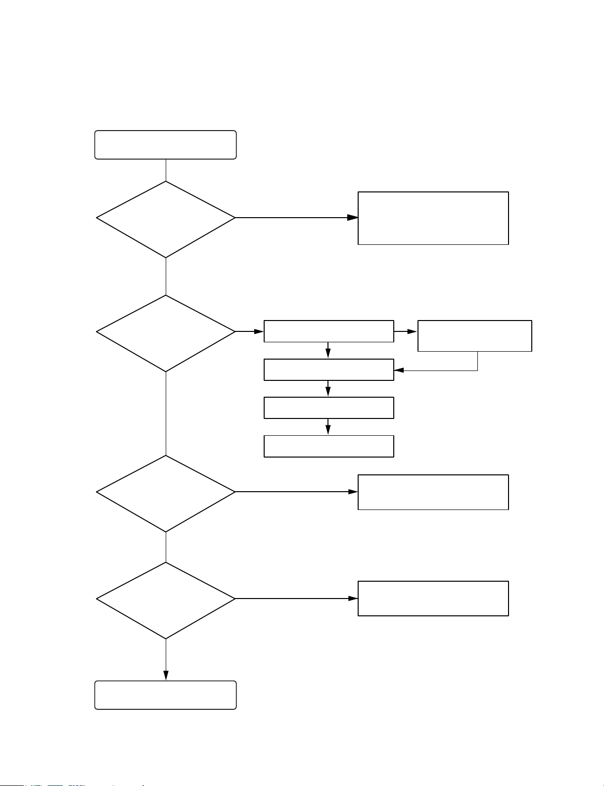
TROUBLESHOOTING
Turn power on.
Is power on?
Does initial read work?
Does it play?
Does it output audio?
Check power supply circuit.
PN807 PIN5, 6.2V
PN807 PIN7, 5V
IC803 PIN 2, 3.3V
Check the connector
PN801, PN802, PN809
Check the tracking servo circuit.
Check the PN807 PIN1, 3
OK
YES
YES
YES
YES
YES
YES
NO
NONO
Check the DISK turns
Check the Laser
Check the focus circuit
Check the TRAKING circuit
NO
NO
Page 2
- 2-4 -
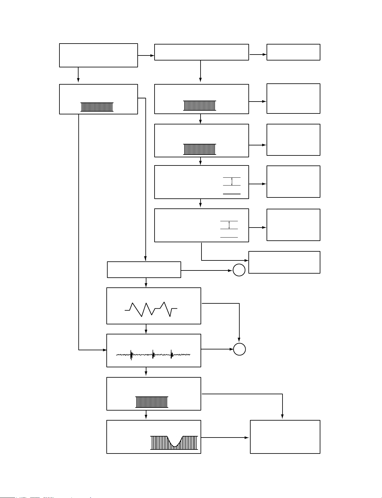
Fails to initial read
A
B
2V
5V
0V
5V
0V
1V
0V
1.2V
0V
0.8V
NO NO
NO
NO
NO
NO
NO
NO
NO
NO
YES
YES
YES
YES
YES
YES
YES
YES
YES
YES
YES
YES
Disc motor turns
Does RF waveform appear?
IC801 Pin3
Check the Data transmission from
PN809 pin11 to CD DSP
Check the Data transmission from
PN809 pin13 to MICOM
Check the change of SLDO
Voltage(IC801 pin23)
Check the change of SL +,
SL - Voltage
(IC802 pin 18, 19)
Check the Voltage change of PN 809
PIN20(OPEN, CLOSE)
Defective connector
PN809
Defective connector
PN809, Defective
MICOM
Defective connector
PN809, Defective
IC801
Defective IC801
Defective IC802
Defective contact PN802
Defective PICK-UP
Does laser light?
focus coil drive wareform.
TRACKING ERROR wareform
Is rotation normal?
Defective IC801
Defective PICK-UP
Is there no dropout of RF signal?
Does FA+ waveform appear at
IC802 pin13?
Does TE waveform appear at
801 pin 15?
Page 3
- 2-5 -
NO
NO
NO
NO
NO
NO
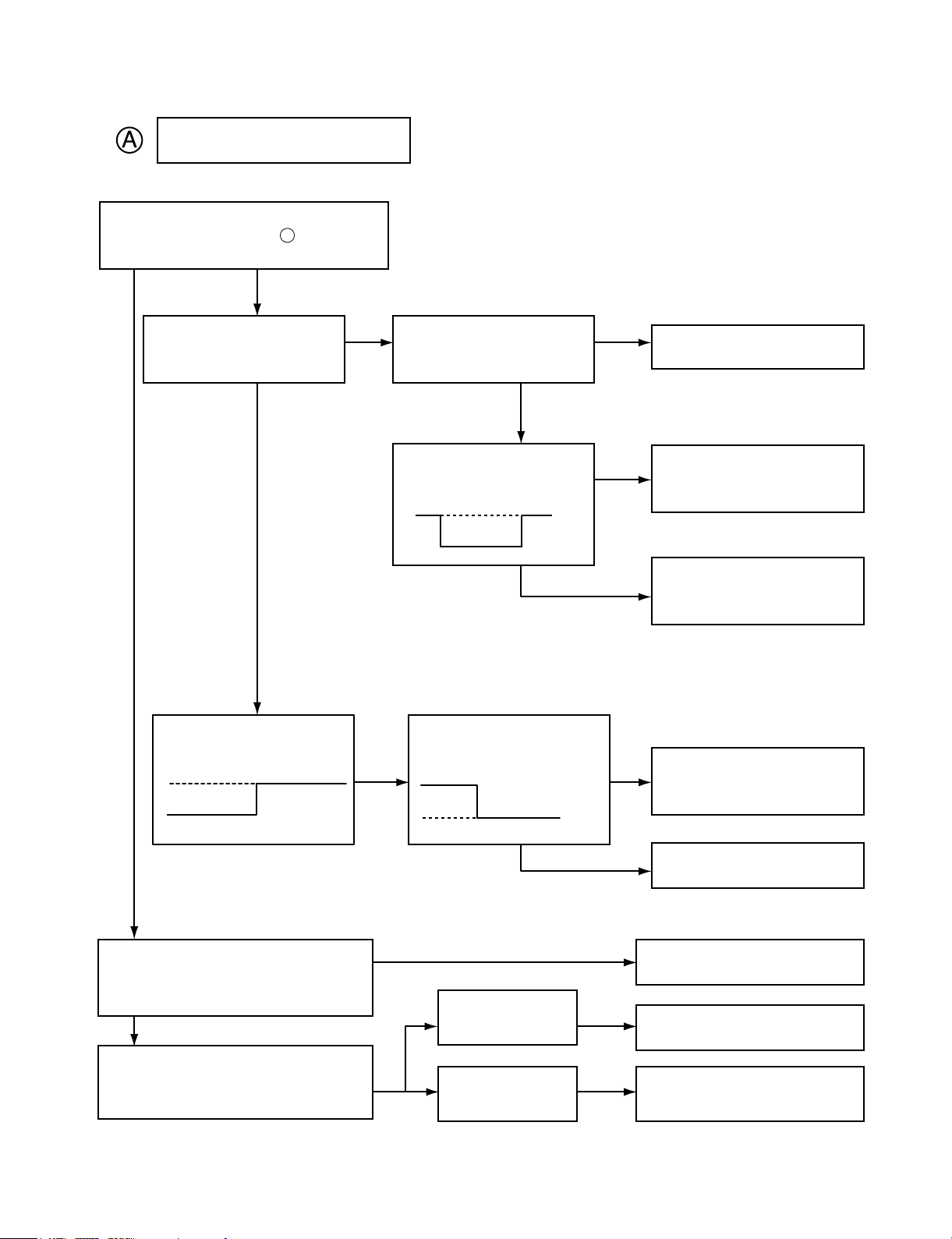
Laser does not light.
Is “3.5V” applied to pin of IC 801?
Is power supplied to laser Q801?
(Q 801 collector: about 1.8V)
Does laser current flow?
1.0V across R808
Is data transferred from
MICOM IC ?
Does voltage appear at IC
802 pin 17, 18?
Defective MICOM.
Defective MICOM.
Defective connector.
Defective IC 801, 802
Defective slide motor and/or
connector.
Defective LMT SW and/or
connector.
Defective Q 801 and/or laser.
Defective laser and/or
connector.
Did pickup return to
innermost circular?
Does it stop at inner pick
circular after shift?
Is defect output from LM
SW applied to pin 2 of
PN802?
R808»1.0V
R808«1.0V
YES
YES
YES
YES
OPEN
CLOSE
YES
YES
YES
YES
YES
YES
70
Page 4

- 2-6 -
B
NO
NO
NO
NO
NO
YES
YES
YES
YES
Laser lights
Does lens move up/down?
Check the signal of
FOCUS SEARCH
(IC801 Pin 21)
Chekc the signal of PN802
pin 13, 14
Does FE signal appear?
(IC801 pin 13)
Does DRF signal appear? (IC 801 pin67)
Defective IC801
Defective IC802
Open activator and/or connector
Defective IC801
Degraded laser diode
Defective PICK-UP
Page 5

- 2-7 -
(CH1)
(CH2)
1. HF signal (RF signal ) waveform
(IC801 pin 3) during normal play
2. EFM signal (IC801 pin 3)waveform
during Normal Play
3. Focus coil drive waveform(IC802 pin13)
• When focus search failed or there is no disc on the tray
• Focus coil drive waveform(FDO: IC801 pin21) and
DRF(IC801 pin67) when focus search is accomplished
4. Tracking coil drive waveform and TE during track
traverse
(1) When time division is 20mS/Div.1V/Div.
(2) When time division 1mS/Div, 1V/Div
(During forward track traverse)
(3) When time division is 0.5nS/div.
(During backward Track Traverse)
5. Feed motor drive waveform(IC 802 pin18)
During normal play
CH1 : FOCUS COIL DRIVE
SIGNAL 2V/Div.
CH2 : DRF
CH1 : TRACKING COIL DRIVE
SIGNAL 2V/Div. (IC802 pin27)
CH2 : TRACKING ERROR(TE: IC801 pin15)
1V/Div.
(
(
(
CH2 : TRACKING COIL DRIVE (IC802 pin27)
SIGNAL 2V/Div.
CH2 : TRACKING ERROR (TE: IC801 pin15)
1V/Div.
(
CH1 : TRACKING COIL DRIVE (IC802 pin27)
CH2 : TRACKING ERROR (TE: IC801 pin15)
(
0.5V/Div.
500nS/Div.
(
1S/Div.
1V/Div.
(
1mS/Div.
1V/Div.
(
0.5V/Div.
5µS/Div.
(
2S/Div.
0.5V/Div.
OV
OV
OV
(CH1)
(CH2)
(CH1)
(CH2)
(CH2)
OV
OV
OV
OV
OV
OV
OV
OV
OV
WAVEFORMS OF MAJOR CHECK POINT
Page 6

- 2-8 -
VKK PART
Does DC - 33V appear at
CN302 Pin .
Check the Voltage of IC301
pin51
Dose -33V appear at
ZD704(-)
Check the Q701
TURN ON
Check the PATTERN
Replace the ZD704
Replace the Q701
Refer to power circuit
END
Check the -33V(LOW)
of C740
Replace the D709,
D710
YES
YES
NO
NO
P-SENS PART
Does +5V appear at ZD701?
Check the pattern of
IC301 Pin .
Check the waveform
of D708(cathod).
Check the R743 and
replace ZD703.
Replace the D708.
YES
YES
NO
NO
26
28
Page 7

- 2-9 -
Power Circuit
Muting circuit (MUTE)
Check the Fuse
Check the DC output
of C770(+), C720(-)
Check the DC Output of
C728(+), C778
Check the Voltage
output of IC704, IC707, IC717
Check the Voltage
Output of IC705, IC706
Check the 5V of CN513
pin 7(CD FUNCTION)
END
Dose “Low” appear at
Q402 “B”
check the “High” of Q401,
Q451 “B”
MUTE
Replace the Fuse
Check the AC Output of
CN701 pin1, 2, 5, 6
Check the AC Output of
CN701 PIN 7, 8
Replace the IC704
Replace the D720
Replace the D720, D721,
D722, D723
Check the IC704, IC707,
IC717
Check the “High” of
IC301 pin82
Check the “Low” of Q791“B”
Check the connector of
Q402 “B” and GND
Replace the TR
Check the Q791, CD Ass’y
Check the power Ass’y or
Replace the Transformer
Check the power Ass’y
or Replace the
Transformer
Check the 5V of IC301
PIN17, 46, 72 ,90
Replace the Q792
Check the “High” of
IC203 pin 14
Check the IC203
YES
YES
YES
YES
YES
YES
YES
YES
YES
YES
YES
YES
YES
NO
NO
NO
NO
NO
NO
NO
NO
NO
NO
NO
NO
Page 8

- 2-10 -
Audio abnormal
SPK Relay Troubleshooting
Check the output of
IC401 Pin 24, 25
Refer to “IC401
Troubleshooting”
Refer to “Muting
Troubleshooting”
Check the Valtage of IC701, pin
1, 2, 5, 6 & Check the power
circuit
Refer to “Spk Relay
troubleshooting”
Refer to “power circuit”
Check “High” of Q763 “B”
Refer to “IC203
Troubleshooting”
Replace the RELAY(RY710)
Replace the Q763
Check the input of
IC701 pin14, 18
Check the Output of IC701,
pin8, 9, 10, 11
Check the RY701
END
Check the 12V of R794(+)
Check the “Low” of Q763 “C”
Check the output
END
YES
YES
YES
YES
YES
YES
YES
YES
NO
NO
NO
NO
NO
NO
NO
NO
Page 9

- 2-11 -
FUNCTION MODE Audio abnormal
TAPE
Check the signal input of IC401 pin 28, 37
Refer to “IC202 Troubleshooting”
AUX
Chekc the signal input of IC401, pin 29, 36
Check the signal input of JK401
Check the signal input of IC401 pin 31, 34
Check the signal of CN513 pin 1, 3 or
Refer to “CD Troubleshooting”
Check the signal input of IC401 pin 30, 35
Refer to “IC102 Troubleshooting”
CD
Tuner
Check the “Low” of Q205 “B”
Refer to “IC504 Troubleshooting”
MIC
Page 10

- 2-12 -
Refer to “IC301
Troubleshooting”
IC301 Troubleshooting
IC203 Troubleshooting
Check the power supplying IC301 Pin 17, 46, 72, 90?
Refer to “Power Circuit Troubleshooting”
Check the P-SENS
Replace the X301
Check the RESET circuit
Refer to “Power Circuit Troubleshooting”
Check the Data of IC301 Pin 3, 4
(CD ➞ TAPE FUNCTION)
Replace the
IC203
Check the pattern
of (IC301 & IC203)
Check the 5v of IC301 pin26
Check the oscillation of X301
When power supplying to IC301 pin11.
(High ➞ Low ➞ High)
Replace the IC301
Check the power supplying to IC203 pin16
Check the CLK Data of IC203 pin 2, 3
Check the CONTROLL function
END
YES
YES
YES
YES
YES
YES
YES
NO
NO
NO
NO
NO
NO
NO
Page 11

- 2-13 -
IC401 Troubleshooting
IC701 Troubleshooting
Check the power supplying to IC401 Pin 39
Refer to “Power Circuit Troubleshooting”
Check the IC301 pin 85, 86, 75, 76
Check the PATTERN of MICOM
(85, 86)& IC401(21, 22)
Refer to “Muting Troubleshooting”
Refer to “power circuit Troubleshooting”
Replace the IC401
Replace the “IC301
Troubleshooting”
Replace the IC401
Check the Pulse waveform of IC401 pin21, 22
(VOL DIAL)
Check the Output of IC401 pin 32, 33
Check the waveform Output of IC401 pin24, 25.
Check the signal input of pin 14, 18
Check the power of pin1, 2 (+) pin 5, 6 (-)
Check the signal Output of pin 8, 9, 10, 11
END
END
YES
YES
YES
YES
YES
YES
YES
YES
NO
NO
NO
NO
NO
NO
NO
Page 12

- 2-14 -
FM (TUN101)
Check the 10V input of TUN101 B+ 6
Check the “High” Voltage of TUN101 VT 5
Check the OSC waveform of TUN101 Pin 8
Refer to “IC102 Troubleshooting”
Check the 12V of Q102 “E”
Refer to “Power
Circuit Trouble-
shooting”
Check the “LOW” of IC103 Pin 7
Refer to “IC103
Troubleshooting”
Replace the Q102
Replace the TUN101
Replace the TUN101
YES
YES
YES
YES
YES
NO
NO
IC102 Troubleshooting
Check the power supplying(10V) to pin8
Check the waveform of Pin 20, 21
Check the waveform output of Pin 16, 17
END
Refer to “Power Circuit
Troubleshooting”
Check the FM(TUN101) & AM(L107)
Replace the IC102
Replace the IC102
Check the “Low” of Pin 13
Refer to “IC103
Troubleshooting”
YES
YES
YES
YES
NO
NO
NO
NO
NO
Page 13

- 2-15 -
IC103 Troubleshooting
Check the power supplying to pin 17
Check the oscillation of X104
Check the waveform of CE, DI, DO, CLK
Is the normal ?
END
Refer to “Power Circuit
Troubleshooting”
Replace the X104
Check the line orrefer to “IC 301
Troubleshooting”
CE: Chip Enable
DI: Data Input(from u-com)
DO: Data Output(to u-com)
CLK: Tuner mode clock
Replace the IC103
YES
YES
YES
YES
NO
NO
NO
NO
AM•COIL Troubleshooting
Check the “High” of L107 Pin 2
Refer to “IC103 Troubleshooting”
Replace the L107
Check the oscillation of L107 Pin 13
Refer to “IC102 Troubleshooting”
YES
YES
NO
NO
Play
Check the VCC supplying to IC202 pin 18
Refer to “Power Circuit Troubleshooting”
Check the Deck Mecha
Replace the Deck
Mecha.
Replace the IC202
Check the signal output of IC202 pin 5, 20
Check the Muting Circuit
YES
YES
YES
NO
NO
NO
Page 14

- 2-16 -
REC (Q252, Q202 ON / R273, R223 High)
Check signal supplied to IC202 pin 11, 14?
Check the output of IC202 Pin9, 16
Check the IC201 pin6 : 12V and pin 4 : High
Check the power or Refer to “IC203
Troubleshooting”
Check the power
supplying to C236(+)
Check the 0.6V of Q208
“B”
Check the “Low” of
Q208 “C”
Replace the Q207
END
Check the Vcc power of IC202 Pin18
Check the oscillation of L203 pin 2, 3
Replace the DECK
Check the “Low” of Q253,
Q203 “B”
Replace the Q253, Q203
Refer to “IC203
Troubleshooting”
Refer to “Power Circuit
Troubleshooting”
Refer to “IC203
trouleshooting”
Replace the Q208
Replace the L203
YES
YES
YES
YES
YES
YES
YES
YES
YES
NO
NO
NO
NO
NO
NO
NO
NO
NO
Page 15

- 2-17 -
YES
YES
NO
Dubbing(“NORMAL or REC “//“HIGH”)
Q252, 202 “OFF”//“ON” : R273, 223
“LOW”//“HIGH
Q253, 203 “ON”//“OFF” Refer to “IC203 Troubleshooting”
Refer to “REC Troubleshooting”
 Loading...