


ASSEMBLY &
USER MANUAL
GOLDMUND REFERENCE II

Table of Contents
1. UNPACKING 4
2. CHOICE OF YOUR TURNTABLE LOCATION 4
3. TURNTABLE ASSEMBLY 5
4. TONE ARM ASSEMBLY 19
5. USER INSTRUCTIONS 20
6. CLEANING AND MAINTENANCE 21

I M P O R T A N T !
The Goldmund Reference II you just purchased
represents a summit in terms of design,
concept and quality of reproduction.
Therefore, great care should be taken before
attempting to put the unit together. Read the
instruction manual carefully. This will eliminate
the risk of damage or loss in performance.
WARNING!
PLEASE READ INSTALLATION MANUAL
COMPLETELY PRIOR TO INSTALLATION.
PLEASE DO NOT CONNECT ANY CABLES
OR MOVE ANY PART BEFORE READING
THE FOLLOWING INSTRUCTIONS.
OBSERVE GENERAL ELECTRICAL SAFETY
PRECAUTIONS PARTICULARY WITH
REGARD TO AVOIDING WATER, MOISTURE
AND HEAT. TO REDUCE THE RISK OF
ELECTRIC SHOCK, DO NOT REMOVE THE
COVERS AND REFER SERVICING TO
QUALIFIED PERSONNEL.
______________________________________
The Goldmund Reference II – Assembly manual
3

WARNING!
PLEASE READ INSTALLATION
MANUAL COMPLETELY PRIOR
TO INSTALLATION.
3 PERSONS ARE NECESSARY
TO INSTALL THIS TURNTABLE
1 UNPACKING
Your turntable is shipped in 4 separate wood boxes labeled 1 to 4 and 1 carton box labeled
5:
- Box 1: the base (feet assembly)
- Box 2: the table top
- Box 3: the tripod
- Box 4: all mechanical parts to be assembled
- Box 5:the power supply
The electronic control box is already assembled under the table top.
ATTENTION
Please keep the packaging in case you need to transport the turntable at a later date or if
you have to send it for maintenance.
This packaging has been designed specifically to protect the Reference II turntable in
transit. Use of alternative packaging is likely to result in damage, invalidating warranty.
2 CHOICE OF YOUR TURNTABLE LOCATION
Due to the total weight of your turntable (300kg), please choose the definitive location of
your turntable in order to install it on site.
Locate the player on a support providing the most rigid possible connection to the floor.
Solid coupling is essential, and if your support is standing on a suspended floor, at least
one foot should be located over a supporting beam or close to a supporting wall for an
optimal result.
The Goldmund Reference II – Assembly manual
4
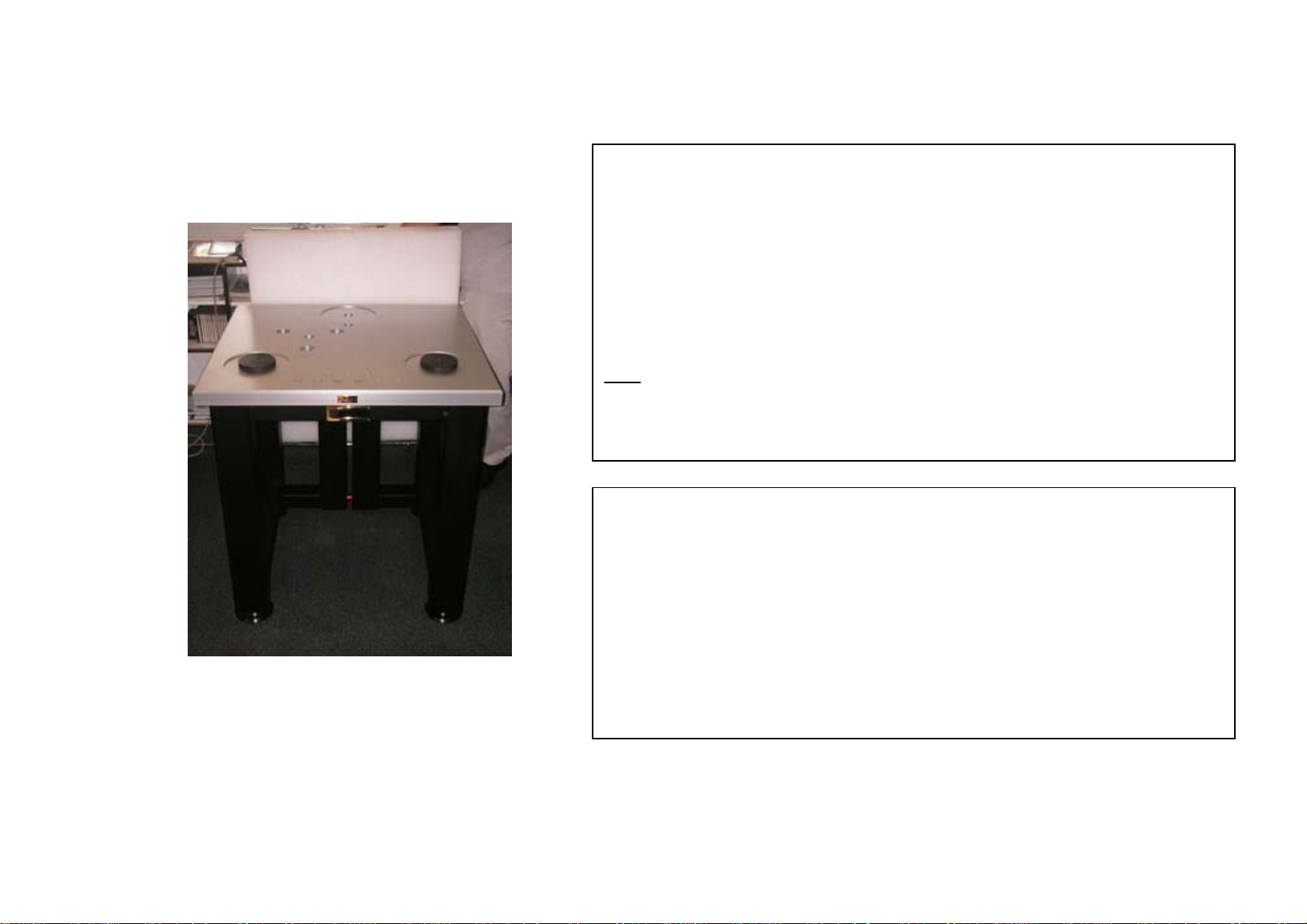
3 TURNTABLE ASSEMBLY
BACK
FRONT
STEP 1
Box 1: the base (feet assembly)
Unscrew and remove the top of the wood box n°1.
Remove the protection cover.
Unscrew and remove a side of the wood box.
Free the feet base and position it at its definitive location, the red bar on the back.
Note
:
Make sure the small screen is facing toward the front, with both central pointes
bolt on the back.
STEP 2
Box 2: the Table top
Unscrew and remove the top cover of the wood box n°2.
Remove the protection cover,
Mount the table top on the base with the control panel keyboard facing the front.
Then, unscrew the cover hiding of the electronics cables below the table.
Free the control panel cables from the base bottom and run all cables through
base.
The Goldmund Reference II – Assembly manual
5
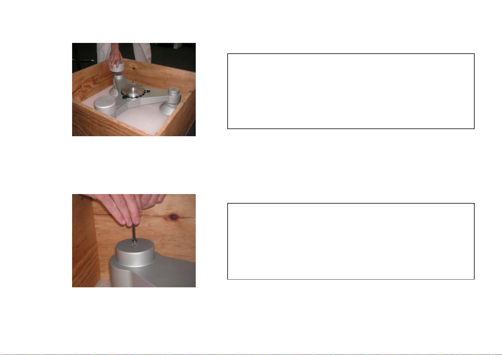
STEP 3
Box 3: Tripod
Unscrew and remove the top cover of the wood box n°3.
Remove the protection cover.
Remove the 3 cylindrical weights sitting on top of the tripod feet.
STEP 4
Box 3: Tripod
Unscrew the tripod from its 3 feet.
Keep the 3 screws that you will use back at the end of the assembly.
The Goldmund Reference II – Assembly manual
6
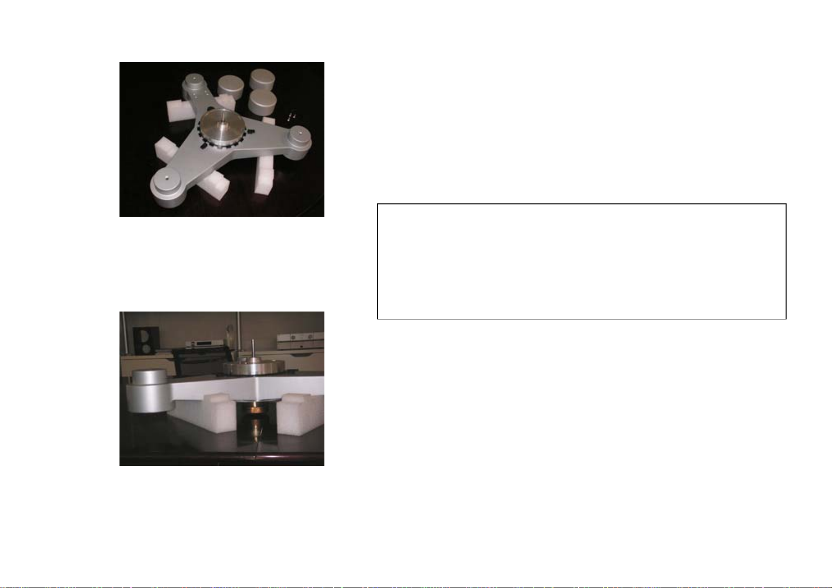
STEP 5
Box 3: Tripod
Free the tripod assembly from the box and set it on 3 temporary supports like
foam rubber or books, leaving the center free.
The Goldmund Reference II – Assembly manual
7
 Loading...