

Page 1
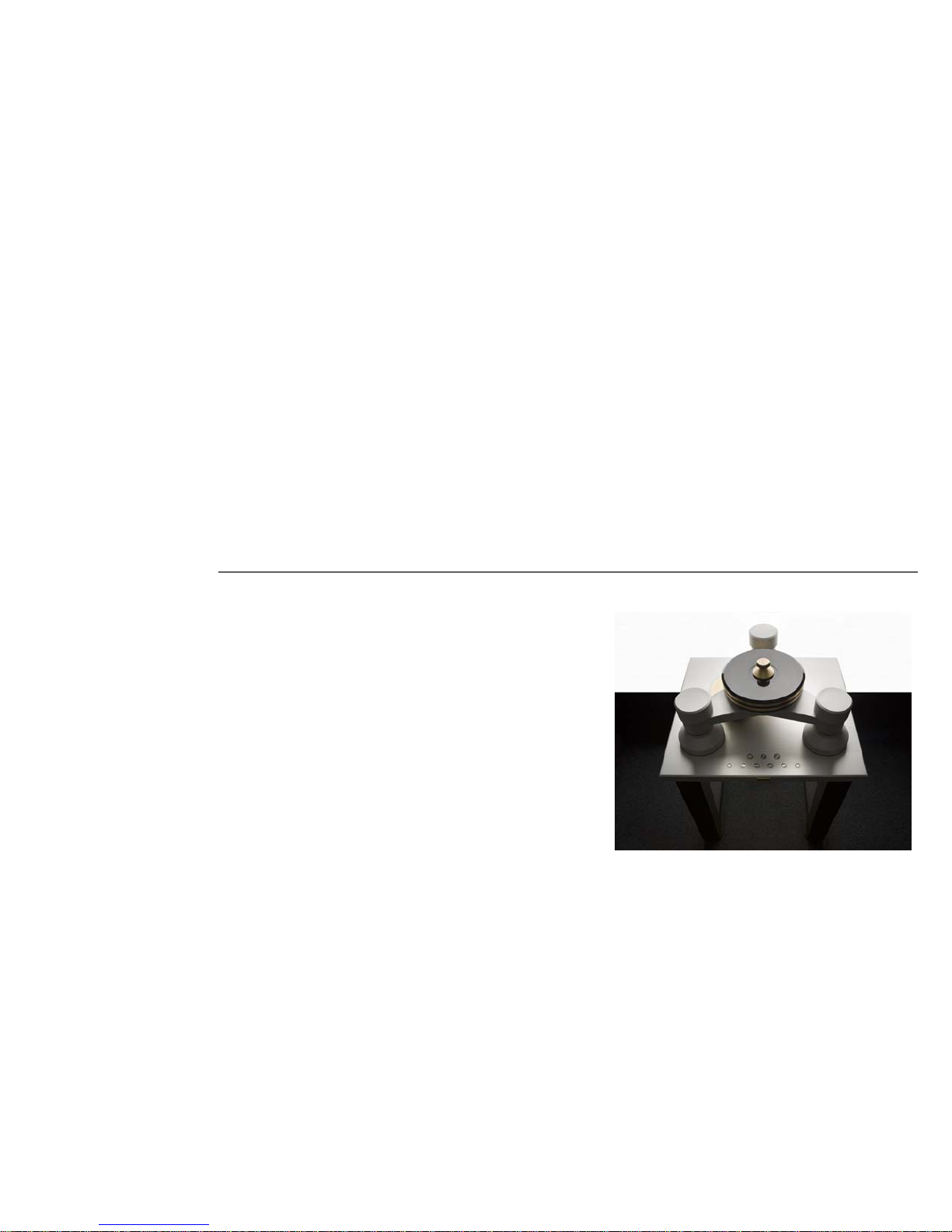
ASSEMBLY &
USER MANUAL
GOLDMUND REFERENCE II
Turntable
Page 2

Congratulations.
Thank you for purchasing the GOLDMUND Reference II Turntable.
You have acquired a highly exclusive and refined limited series product holding a number of new
features that have never been experienced before. Please take some time to read this manual. It
will provide you with useful information to make your pleasure of using the Reference II Turntable
even higher.
INTRODUCTION
GOLDMUND REFERENCE II Turntable
Goldmund was founded in 1978 and has ever since been dedicated to the accurate reproduction of
sound and image.
At Goldmund, we strive to lead in the creation, development and manufacture of the industry’s
most advanced technologies, including audio and video systems, home - networking and music
distribution.
The guiding principle at Goldmund is to produce a precise sound with the least possible loss of
quality through the different stages. Goldmund will never adopt a technology before it is sufficiently
developed to satisfy the high quality standards we set. This is why Goldmund has often rejected
mainstream technologies and developed its own.
Page 3

GOLDMUND REFERENCE II - Assembly Manual - 3
Table of Contents
1 UNPACKING 5
2 CHOICE OF TURNTABLE LOCATION 5
3 TURNTABLE ASSEMBLY 6
4 AMPLIFIER CONTROLS 20
5 USER INSTRUCTIONS 21
6 CLEANING & MAINTENANCE 22
Page 4

GOLDMUND REFERENCE II - Assembly Manual - 4
W A R N I N G !
The Goldmund Reference II you just purchased
represents a summit in terms of design,
concept and quality of reproduction.
Therefore, great care should be taken before
attempting to put the unit together. Read the
instruction manual carefully. This will eliminate
the risk of damage or loss in performance.
PLEASE READ THE INSTALLATION
MANUAL COMPLETELY PRIOR TO
INSTALLATION.
PLEASE DO NOT CONNECT ANY CABLES
OR MOVE ANY PART BEFORE READING
THE FOLLOWING INSTRUCTIONS.
OBSERVE GENERAL ELECTRICAL
SAFETY PRECAUTIONS PARTICULARY
WITH REGARD TO AVOIDING WATER,
MOISTURE AND HEAT. TO REDUCE THE
RISK OF ELECTRIC SHOCK, DO NOT
REMOVE THE COVERS AND REFER
SERVICING TO QUALIFIED PERSONNEL.
Page 5

GOLDMUND REFERENCE II - Assembly Manual - 5
1 UNPACKING
Your turntable is shipped in 4 separate wood boxes labeled 1 to 4 and 1 carton box labeled
5:
- Box 1: the base (feet assembly)
- Box 2: the table top
- Box 3: the tripod
- Box 4: all mechanical parts to be assembled
- Box 5: the power supply
The electronic control box is already assembled under the table top.
ATTENTION
Please keep the packaging in case you need to transport the turntable at a later date or if
you have to send it for maintenance.
This packaging has been designed specifically to protect the Reference II turntable in
transit. Use of alternative packaging is likely to result in damage, invalidating warranty.
2 CHOICE OF TURNTABLE LOCATION
Due to the total weight of your turntable (300kg), please choose the definitive location of
your turntable in order to install it on site.
Locate the player on a support providing the most rigid possible connection to the floor.
Solid coupling is essential, and if your support is standing on a suspended floor, at least
one foot should be located over a supporting beam or close to a supporting wall for an
optimal result.
WARNING!
PLEASE READ INSTALLATION
MANUAL COMPLETELY PRIOR
TO INSTALLATION.
3 PERSONS ARE NECESSARY
TO INSTALL THIS TURNTABLE
Page 6
GOLDMUND REFERENCE II - Assembly Manual - 6
3 TURNTABLE ASSEMBLY
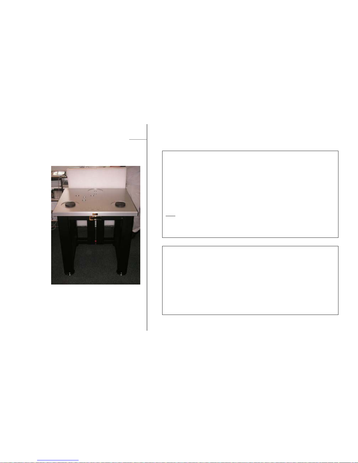
STEP 2
Box 2: the Table top
Unscrew and remove the top cover of the wood box n°2.
Remove the protection cover,
Mount the table top on the base with the control panel keyboard facing the front.
Then, unscrew the cover hiding of the electronics cables below the table.
Free the control panel cables from the base bottom and run all cables through
base.
STEP 1
Box 1: the base (feet assembly)
Unscrew and remove the top of the wood box n°1.
Remove the protection cover.
Unscrew and remove a side of the wood box.
Free the feet base and position it at its definitive location, the red bar on the back.
Note
:
Make sure the small screen is facing toward the front, with both central pointes
bolt on the back.
BACK
FRONT
Page 7
GOLDMUND REFERENCE II - Assembly Manual - 7
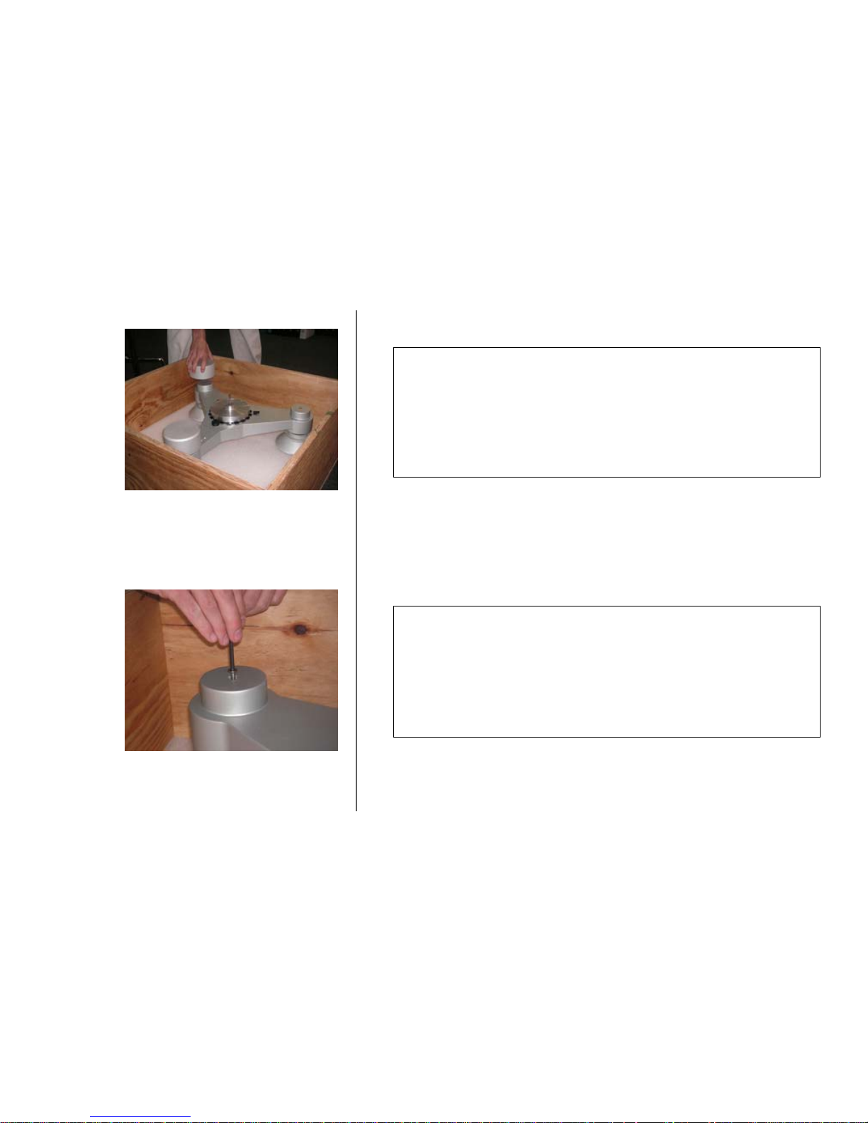
STEP 3
Box 3: Tripod
Unscrew and remove the top cover of the wood box n°3.
Remove the protection cover.
Remove the 3 cylindrical weights sitting on top of the tripod feet.
STEP 4
Box 3: Tripod
Unscrew the tripod from its 3 feet.
Keep the 3 screws that you will use back at the end of the assembly.
Page 8
GOLDMUND REFERENCE II - Assembly Manual - 8
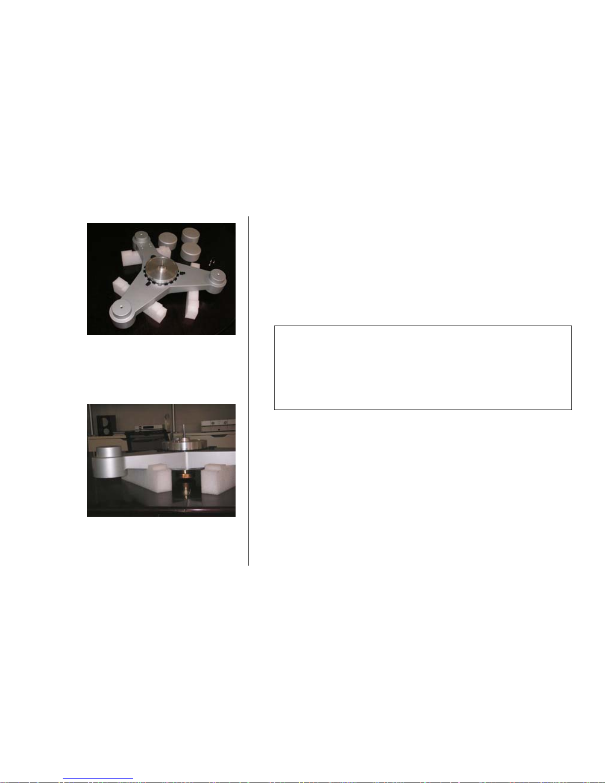
STEP 5
Box 3: Tripod
Free the tripod assembly from the box and set it on 3 temporary supports like
foam rubber or books, leaving the center free.
Page 9
GOLDMUND REFERENCE II - Assembly Manual - 9
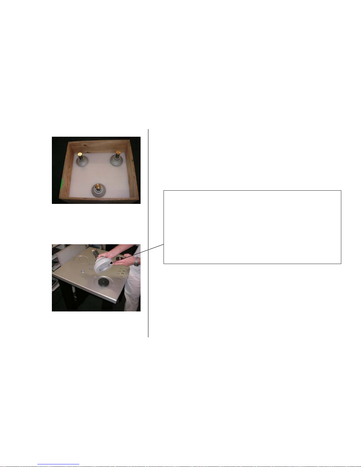
STEP 6
Box 3: Tripod
In the box n°3, you will find the 3 cylinder feet of the tripod.
Please take one cylinder foot to position it at the front left position.
Be carful to select the foot with the correct basis (check the bottom of the foot).
Repeat the operation for the front right cylinder foot.
Page 10
GOLDMUND REFERENCE II - Assembly Manual - 10
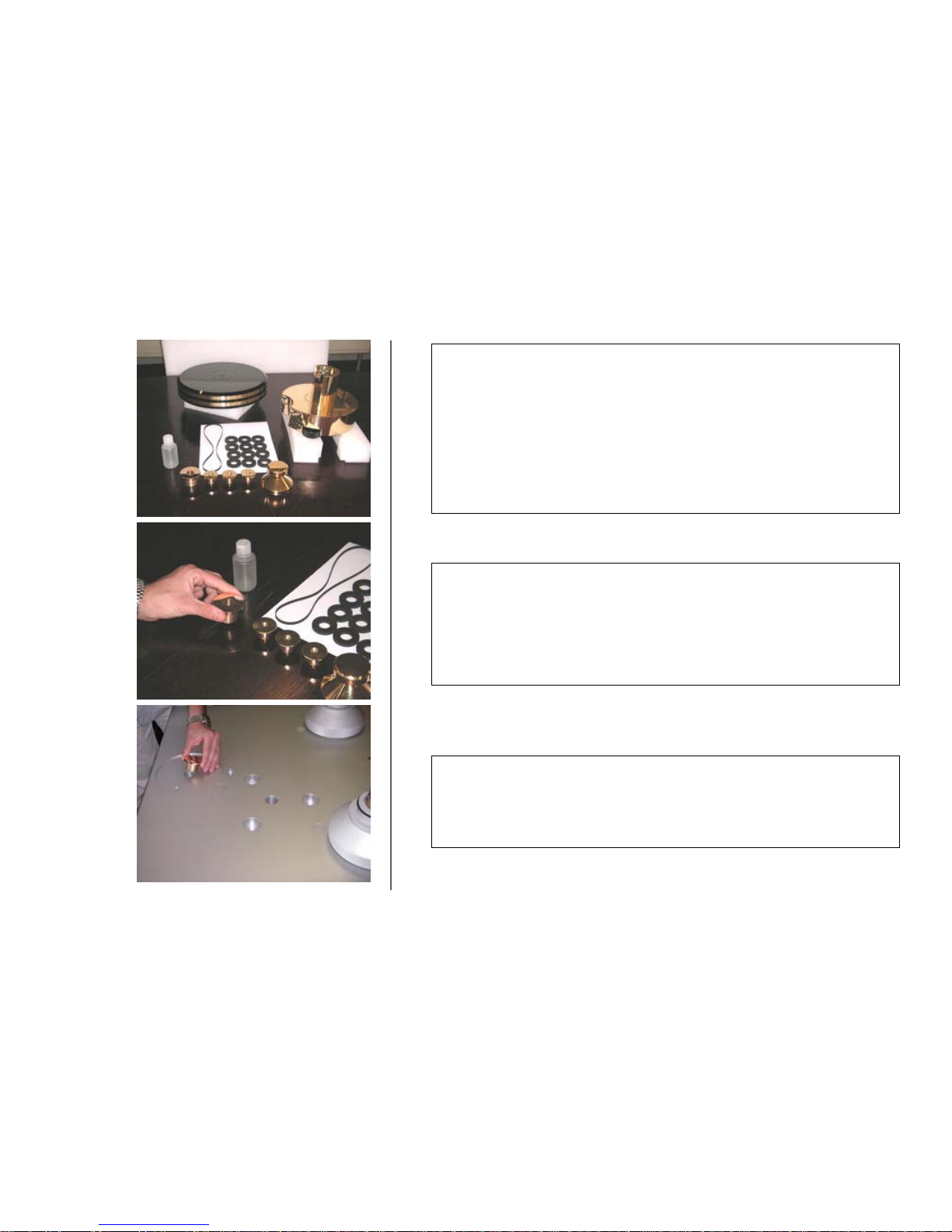
Box 4: Various Parts
In the box n°4, you will find:
- 1 platter
- 1 motor bloc
- 1 belt
- 12 rubber seals
- 1 large golden insert
- 3 small golden insert
- 1 clamp
- 1 small oil bottle
STEP 7
Box 4: Various Parts
Take the large golden insert.
STEP 8
Position it in the center of the third cylinder foot position.
Page 11
GOLDMUND REFERENCE II - Assembly Manual - 11
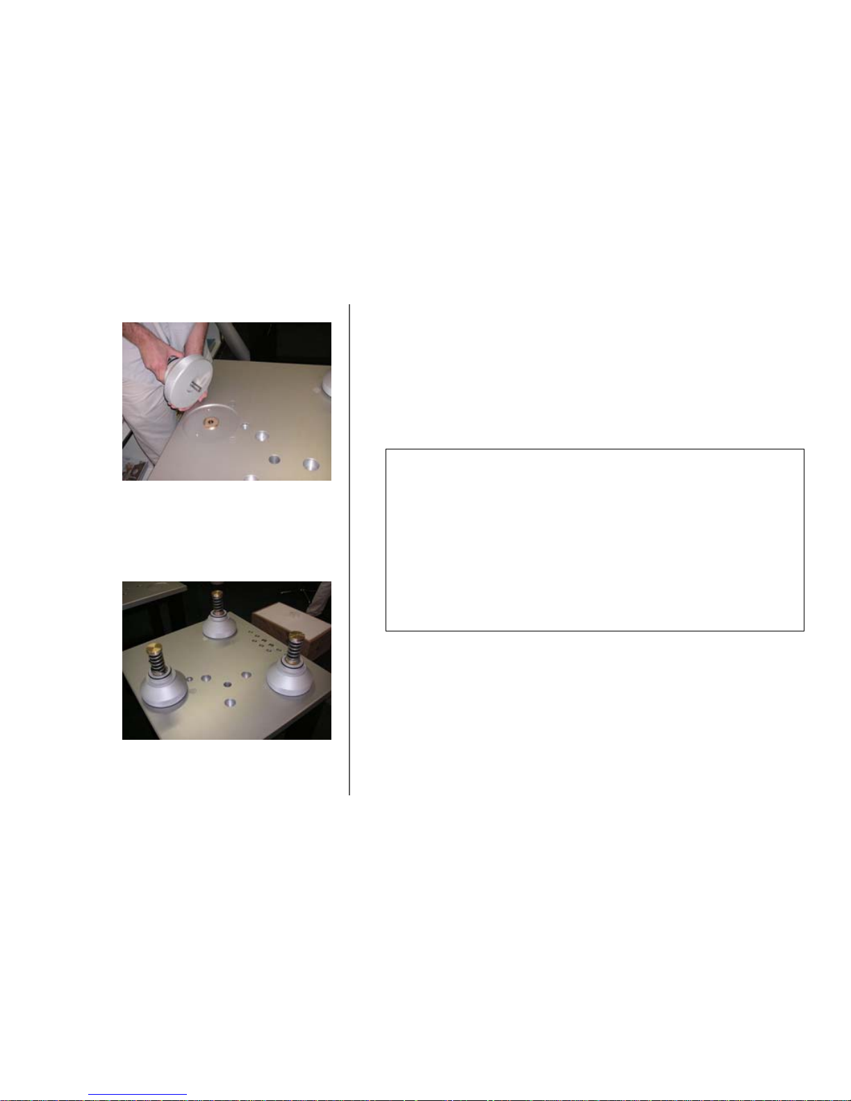
STEP 9
Box 3: the tripod
In the box n°3, take the last cylinder foot.
Check if its design is the same as the one shown on the left picture.
Position it in the bottom of the third cylinder foot position, passing the axe through
the hole.
The 3 cylinder feet are positioned.
Page 12
GOLDMUND REFERENCE II - Assembly Manual - 12
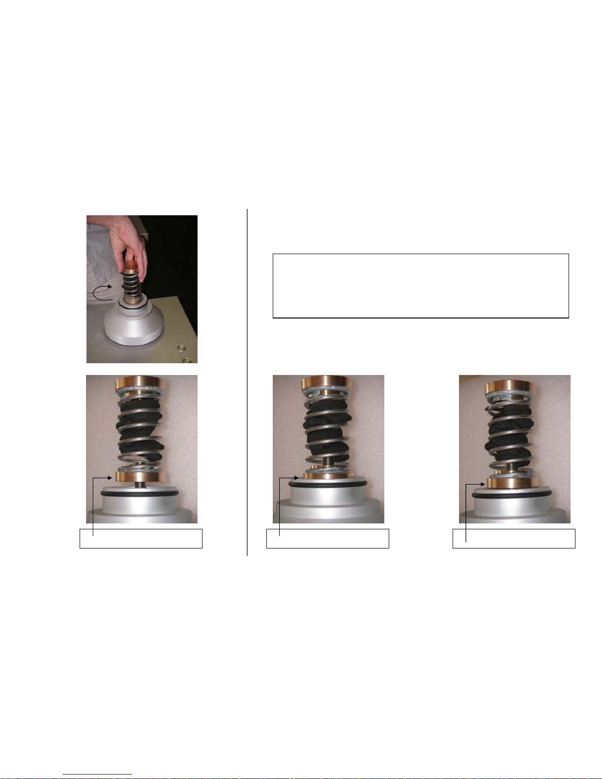
STEP 10
Adjust the 3 springs:
Turn the springs has shown.
Correct position Too High Too low
Page 13
GOLDMUND REFERENCE II - Assembly Manual - 13
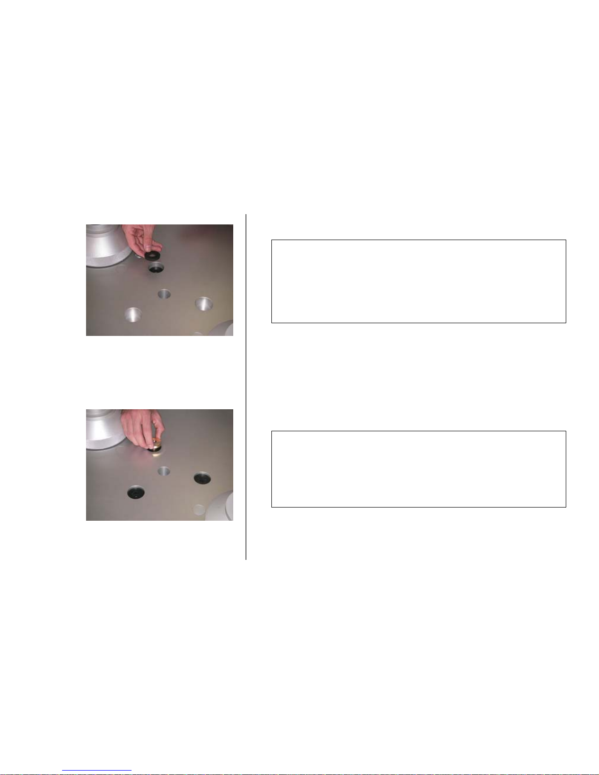
STEP 11
Take 4 rubber seals and insert them in one of the 3 holes on the table: 4 rubber
seals per hole.
Repeat the operation for both other holes.
STEP 12
When the seals are positioned, place 1 golden insert in the hole.
Repeat the operation for both other holes.
Page 14
GOLDMUND REFERENCE II - Assembly Manual - 14
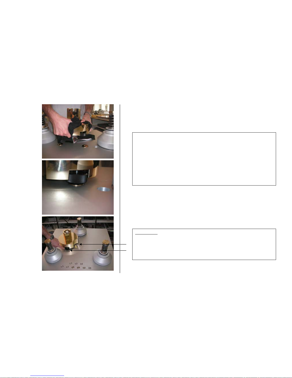
STEP 13
For this step, you need to be 2 persons.
One person take carefully the motor block by its basis and keep in above the 3
holes with the golden insert, as shown on the picture.
The other person runs the cables trough the central hole and leave them hanging
Then the first person can mount the motor on the table, making each black
serrated knurl facing its golden insert.
ATTENTION:
Please check the motor and the motor black knurl is in the same position as the
one shown on the picture.
Page 15
GOLDMUND REFERENCE II - Assembly Manual - 15
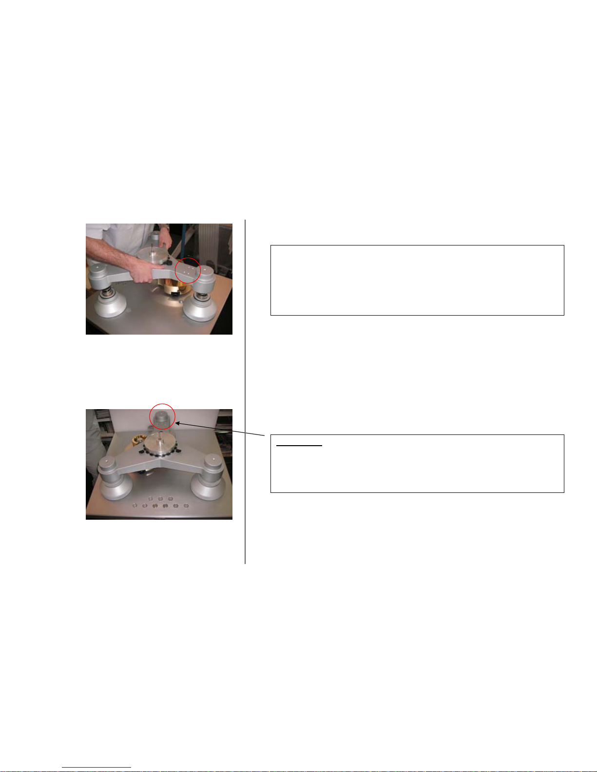
STEP 14
Take the tripod and mount it as shown on the left picture:
The arm with the 4 small holes should be directing towards the rear foot of the
turntable.
ATTENTION:
Please check the tripod is well positioned.
BACK
FRONT
Page 16
GOLDMUND REFERENCE II - Assembly Manual - 16
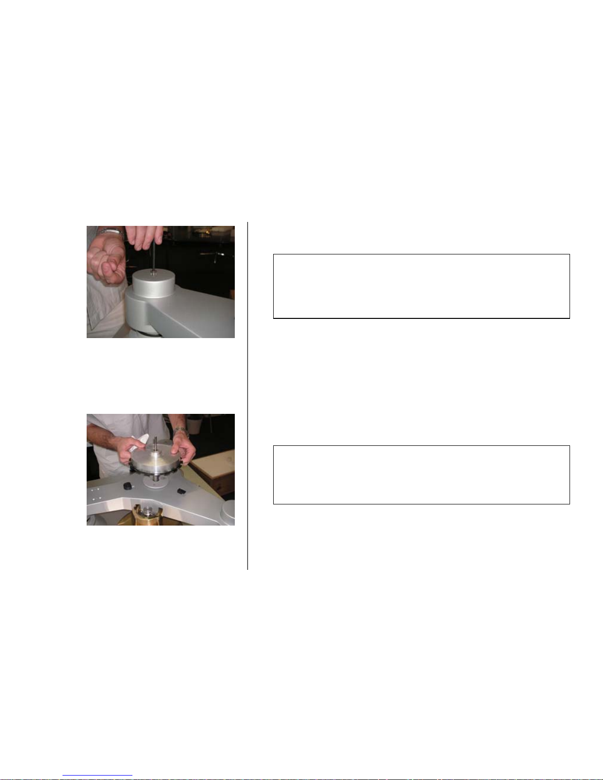
STEP 15
Screw, but not over-tight, the tripod to the feet with the 3 screws dismounted at
the beginning of the assembly (see STEP 4).
STEP 16
Remove carefully the axis from the tripod.
Page 17
GOLDMUND REFERENCE II - Assembly Manual - 17
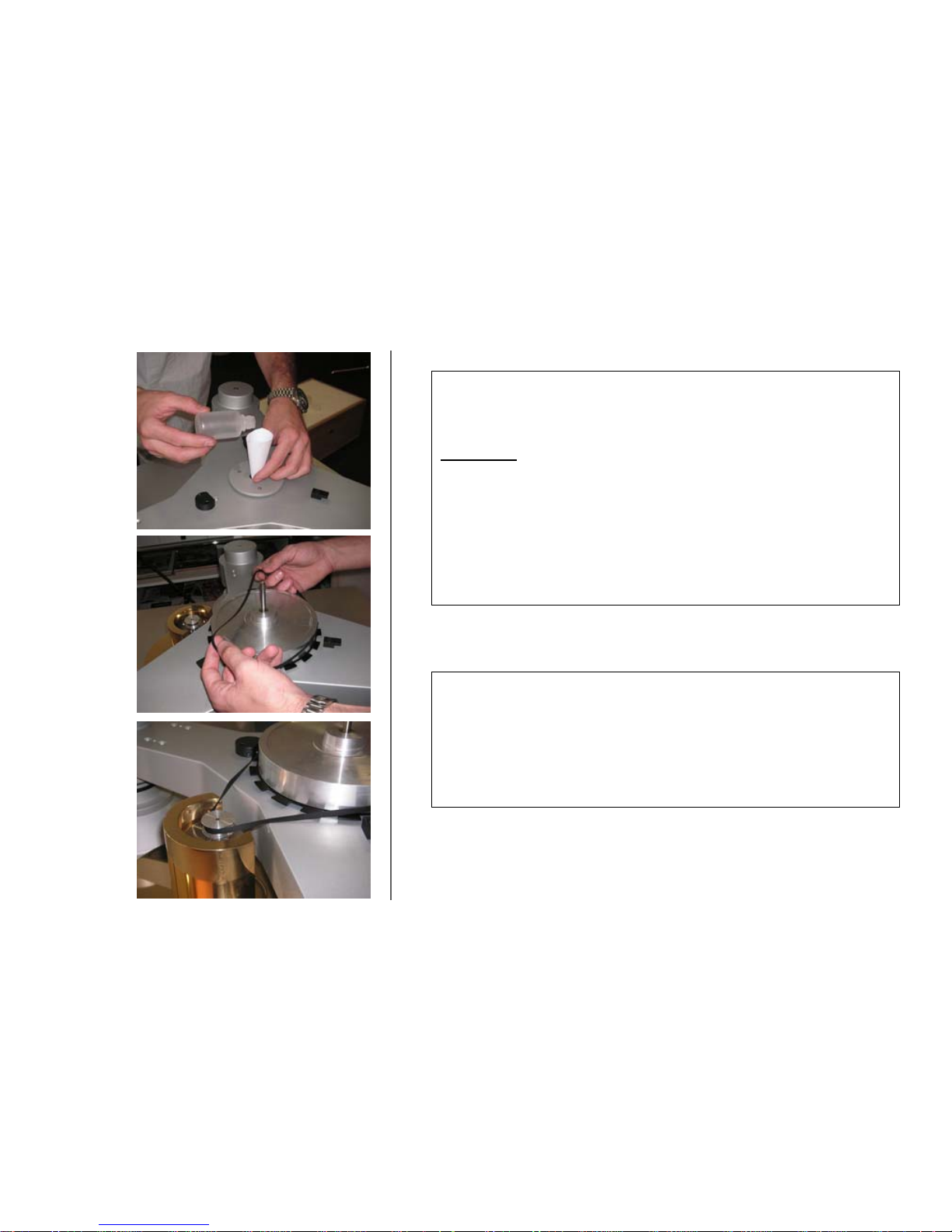
STEP 17
Add some oil contained in the bottle in the axis shaft.
IMPORTANT:
After this step, make sure you clean your hands from any oil.
STEP 18
Reinsert the axis with extreme care into the shaft assembly.
Make the axis descend extremely slowly.
STEP 19
Mount the belt around the axis wheel and the motor pulley as shown on the
pictures.
Check that the belt is flat against drive wheel and motor pulley.
Page 18
GOLDMUND REFERENCE II - Assembly Manual - 18
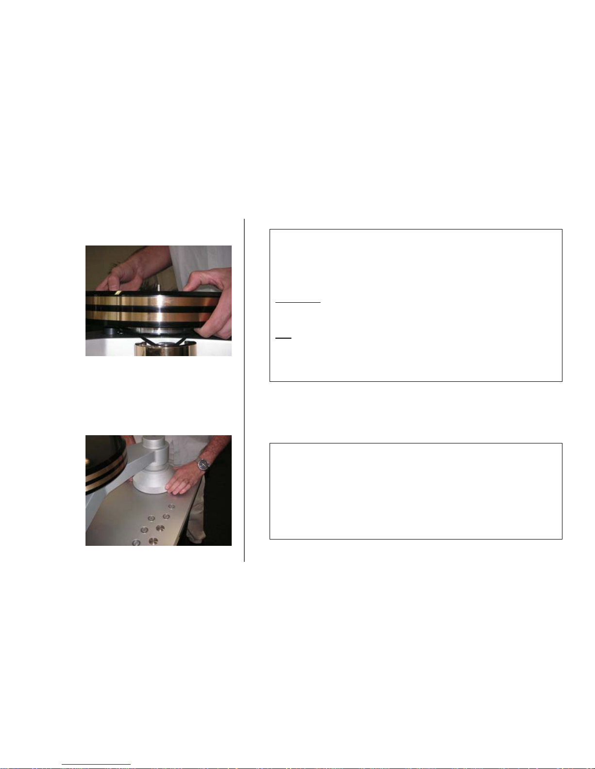
STEP 20
Mount the platter on the center axis.
This should be done with great care and the platter must be set in position very
slowly.
IMPORTANT
The platter shouldn’t at any time be dropped or shocked.
Take great care since the platter is very heavy.
Note
:
To remove the platter, help may be required. Platter can be removed by pulling
straight up slowly. A second person may have to push on the central spindle to
ease the process.
STEP 21
Set the 3 large finish cylinders.
Adjust height and lower the tripod assembly by turning the large adjustment
cylinders.
Level the tripod assembly using a bubble level.
Repeat the operation if necessary.
Page 19
GOLDMUND REFERENCE II - Assembly Manual - 19
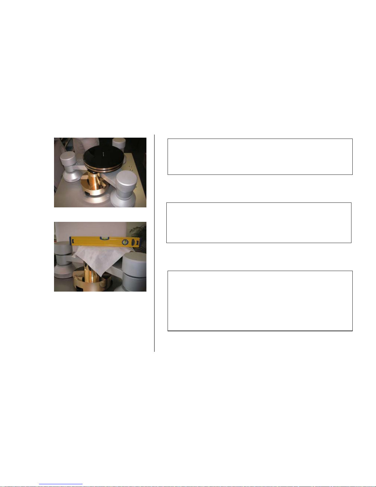
STEP 22
Put the 3 top cylinders on the tripod.
STEP 23
Check the level of the table top first, then the platter with a bubble level.
If needed, repeat step 21 with the platter positioned.
STEP 24
Box 5
Please remove the power supply from its box and position it nearby the turntable.
Then take the connector cable and plug it to the power supply.
Plug the second extremity to into the turntable right central foot base’s socket.
Page 20

GOLDMUND REFERENCE II - Assembly Manual - 20
4 AMPLIFIER CONTROLS
The Goldmund Reference II can be used with most existing ton arms, both pivoting and
straight-line.
Up to three tone arms may be assembled on the turntable.
Even if the Goldmund T8 tone arm is installed, two additional pivoting arms may be used.
Goldmund provides upon request various basis for the most common tone arm lengths
available.
Please consult your Goldmund representative for any further information.
To assemble the Goldmund T8 tone arm, please refer to the tone arm assembly manual.
Page 21

GOLDMUND REFERENCE II - Assembly Manual - 21
5 USER INSTRUCTIONS
Now your turntable is assembled, you can start using it:
1- Switch on the power supply
2- Unscrew the clamp and remove it very carefully.
3- Position the record to play
4- Re-mount the clamp carefully; tighten it holding its basis.
5- Select the speed corresponding to the disc:
• For 33T: press the button “33”
• For 45T: press the button “45”
• For 78T: optional (Please contact your local Goldmund distributor).
6- Position the tone arm on the record
7- To stop the turntable, press the button “STOP” after removing the tone arm.
We recommend leaving the turntable run for a few hours in order to stabilize its
performance.
Note: the bottom line of keys is dedicated to the Goldmund T8 tone arm use. (See separate
user manual).
Page 22

GOLDMUND REFERENCE II - Assembly Manual - 22
6 CLEANING & MAINTENANCE
There is no special maintenance to be done on your turntable. Clean with dust free soft
cloth.
Drive wheel and motor pulley may be cleans after months of use or if abnormal speed
variation occurs.
Note: Clean with Isopropyl Alcohol only. Belt may be changed after heavy use, especially if
it becomes too hard and does not grip enough on the pulley.
WARNING!
Always turn the power off on the power supply before cleaning your turntable.
All enquires relating to product servicing and operation should be referred to the local
authorized retailer supplying and supporting your Goldmund equipment.
RUNNING-IN TIME
The Goldmund Reference II shaft and axis are machined with extreme precision. The
optimal performance can only be reached after approximately 100 hours of use, despite the
initial working period of 50 hours processed at the factory.
 Loading...