

GME TX3540S User Manual

INSTRUCTION MANUAL
Compact fully featured 5 watt UHF CB radio
Compact fully featured remote mount 5 watt UHF CB radio
Compact fully featured remote mic 5 watt UHF CB radio
ScanSuite
™
faster, smarter scanning

CONTENTS
SUPPLIED WITH .................................................................3
INTRODUCTION ................................................................3
IMPORTANT INFORMATION CONCERNING UHF
CB RADIO .........................................................................3
Possible Issues ...........................................................4
Emergency Channels..................................................4
Telemetry Channels ...................................................4
FEATURES .........................................................................4
GENERAL OPERATIONS .....................................................6
TX3510S/TX3520S Front Panel Controls .....................6
LCD Panel .................................................................6
Rear Panel .................................................................6
TX3540S Controller Microphone ................................7
TX3510S/TX3520S Microphone .................................7
TX3540S Controller LCD Panel ...................................7
GENERAL OPERATION ACROSS ALL MODELS ...................8
Keypad Functions ......................................................8
Volume .....................................................................9
Selecting Channels ....................................................9
Squelch .....................................................................9
Signal Meter ..............................................................9
Transmitting ..............................................................9
Time-Out Timer ........................................................10
Backlighting ............................................................10
Bandwidth Filter Settings .........................................11
Dynamic Volume Control ..........................................11
Voice Scrambler .......................................................11
Beep Tone Volume ...................................................12
Silent Squelch Tail ....................................................12
Repeaters and Duplex Mode ....................................12
Priority Channel .......................................................13
Scanning .................................................................13
Open Scan ...............................................................14
Group Scan .............................................................15
Network Scan ..........................................................16
CTCSS and DCS .......................................................18
Selective Calling ......................................................20
Using SelCall ...........................................................20
Responding to SelCall Alert ......................................22
Quiet Mode .............................................................22
Group Calling ..........................................................24
Receive-only Channels .............................................25
Configuration Menu ................................................29
INSTALLATION ................................................................30
General ...................................................................30
TX3510S and TX3540S Installation ..........................30
TX3520S Installation ...............................................31
Microphone .............................................................31
C Power Connection ..............................................32
D
ANTENNA CONNECTION ................................................33
NOISE SUPPRESSION .......................................................33
Wiring .....................................................................34
CTCSS TONE FREQUENCY CHART ....................................35
DCS TONE CHART............................................................36
UHF CB OPERATING FREQUENCIES .................................37
SPECIFICATIONS .............................................................38
SC CONTRACT WARRANTY AGAINST DEFECTS ................39
PAGE 2 I NSTRUCTION MA NUAL T X3510S/ TX3520S /T X3540S T X3510S/ TX3520S /T X3540S I NSTRUCTION MA NUAL PAGE 3

SUPPLIED WITH
TX3510S TX3520S TX3540S
TX3510S Radio TX3520S Radio TX3540S Radio
Mounting Cradle
Microphone
TX3520S Remote Head
Mounting Cradle
Mounting Cradle
Controller Microphone
Microphone Clip Microphone Microphone Extension Lead
DC Lead Microphone Clip 8 Pin to 8 Pin Adapter
Screw Pack DC Lead Microphone Clip
Instruction Manual Connecting Cable DC Lead
Screw Pack Screw Pack
Instruction Manual Instruction Manual
IN TRODUCTION
Your GME TX3510S/TX3520S/TX3540S 80 channel radio
is Australian designed and built and is the most advanced
UHF Citizen Band radio available. It combines the very latest
in electronic hardware with the most up-to-date computer
aided design and manufacturing techniques to produce
an extremely compact mobile radio with outstanding
specifications and performance.
Your radio is designed for unobtrusive mounting in modern
vehicles. With its built-in loud speaker and extremely small
size, it can be mounted in almost any convenient location.
IMPORTANT INFORMAT ION
CONCERNING UHF CB R ADIO
The use of the Citizen Band radio service is licensed in
Australia by the ACMA Radio communications (Citizens
Band Radio Stations) Class Licence and in New Zealand by
the Ministry of Economic Development New Zealand (MED).
A General User Radio Licence for Citizens Band radio
and operation is subject to conditions contained in those
licences.
The class licence for users and equipment operating in the
CB/PRS 477 MHz band has been amended. This radio meets
the new 80 channel standard.
In simple terms the same amount of spectrum is available;
however,
radio transceivers can now operate in a narrower
bandwidth and hence use less spectrum. These radios are
generally referred to as narrowband or 12.5 kHz radios. By
using 12.5 kHz channel spacing instead of 25 kHz, the 40
channels originally allocated can now be expanded to 80
channels thereby doubling the channel capacity and relieving
congestion in the UHF CB/PRS band.
Original 40 channel wideband Radios will continue to operate
on the original 40 channels, however they will not be able
to converse on the newer channels 41 – 80. The newer
narrowband radios will be able to converse with all older 40
channel wideband radios on all channels 1 to 40 as well as the
newer channels allocated from 41 to 80.
The mixing of narrowband and wideband radios in the same
spectrum can cause some possible operating issues
of interference and varying levels of received volume.

POSSIBLE ISSUES
When a new narrowband radio receives a transmission
from an older wideband radio the speech may sound loud
and distorted – simply adjust your radio volume for best
performance.
When an older wideband radio receives a signal from a new
narrowband radio, the speech may sound quiet – simply
adjust your radio volume for best performance.
EMERGENCY CHANNELS
The ACMA has allocated channels 5/35 for emergency use
only. Channel 5 is the primary Simplex Emergency Channel.
Where a Channel 5 repeater is available, you should select
Duplex on CH 5.
NOTE: Channel 35 is the input channel for the Channel 5
repeater therefore Channel 35 should also not be used for
anything other than emergency transmissions.
Depending on how close your receiving radio is to another
transmitting radio, there can be interference from the
transmitting radio if it is using a channel adjacent to the
channel you are listening to. Simply try going up or down a
few channels from the currently selected channel.
The above situations are not a fault of the radio but a symptom
of operating wideband and narrowband radios in the same
bandwidth. This possible interference will decrease over time
as the population of wideband radios ages and decreases.
Further information and updates are available from the
Australian Communications and Media Authority (ACMA)
at www.acma.gov.au and the Ministry of Economic
TELEMETRY CHANNELS
ACMA regulations have allocated channels 22 and 23
for telemetry only applications and have prohibited the
transmission of speech on these channels. Consequently your
radio has a transmit inhibit applied to channels 22 and 23.
In the event additional telemetry/telecommand channels are
approved by the ACMA, these channels shall be added to
those currently listed where voice transmission is inhibited.
Currently transmissions on channels 61, 62 and 63 are also
inhibited and these channels are reserved for future allocation
Development (MED), Radio Spectrum Management at:
www.rsm.govt.nz
FEATURES
TRANSMIT (TX)
Individually Programmable DUPLEX Function: User selectable for only those individual channels in your area that have
repeaters, leaving the others free for use as extra simplex channels.
RECEIVE (RX)
Silent Squelch Tail: Eliminates the Squelch noise burst normally audible when the Squelch closes
User Programmable Receive Channels: 95
Signal Receive Indicator: Confirms that an incoming signal is being received
SCANNING AND MEMORY FUNCTIONS
Microprocessor Controlled Frequency Synthesiser: Allows user programmable control of scanning, channel memories
and selected feature options.
Programmable Scan Function
functions available.
PAGE 4 I NSTRUCTION MA NUAL T X3510S/ TX3520S /T X3540S T X3510S/ TX3520S /T X3540S I NSTRUCTION MA NUAL PAGE 5
: Scans the selected UHF CB channels with Group, Open and Network scan

Priority Channel: A user programmable Priority channel feature allows your working channel to be instantly recalled at the
press of a key.
SIGNAL PROCESSING
Digital Signal Processing:
digital format. Allows advanced RF and audio processing techniques to be applied to maximise the radio’s performance.
Advanced Signal Management: Identifies interference caused by strong local signals on adjacent channels and prevents
these from opening your Squelch. ASM also minimises distortion on reception by fine tuning the receiver frequency to match
that of the incoming signal.
Dynamic Volume Control: Automatically compensates for variations in received audio level to provide a constant audio
output level to the speaker.
User Selectable Wide/Narrow Band Filter: To accommodate the blending of 80 channel narrow band radios with older
40 channel wideband radios.
PRIVACY FUNCTIONS
Voice Inversion Scrambler: When activated, scrambles your voice so that communications are only intelligible to others
using the same scrambler technology.
Inbuilt CTCSS & DCS: User selectable Continuous Tone Coded Squelch System and Digital Coded Squelch system provides
silent operation on individual channels.
In-Built SelCall with Quiet Mode: Provides selective calling of individuals or groups with fully user-adjustable 5-tone
transmitted SelCall Ident. Also allows alphanumeric naming of up to 10 Idents for easier caller identification.
PHYSICAL PROPERTIES
Over Voltage Protection: Special overvoltage detection circuitry protects the radio and warns of excessive voltage
conditions by flashing the display.
Rugged Construction: With Die-cast Chassis
USER CONTROLS AND INTERFACE
Full Spectrum Backlighting: User adjustable, totally customisable backlight settings to match the vehicles dashboard
lighting or drivers preference.
High Contrast Liquid Crystal Display: Fully detailed LCD provides a visual indication of the selected channel and all
selected functions at a glance.
Front and Rear Microphone Inputs: Convenient front and rear microphone inputs to facilitate ease of installation and
operation across a range of vehicles.
Digital Signal Strength Meter: Provides a numeric signal strength indication in numbers from 0 to 9+
Measures, filters and compresses standard analogue audio signals and converts them into
GENERAL OPERATIONS
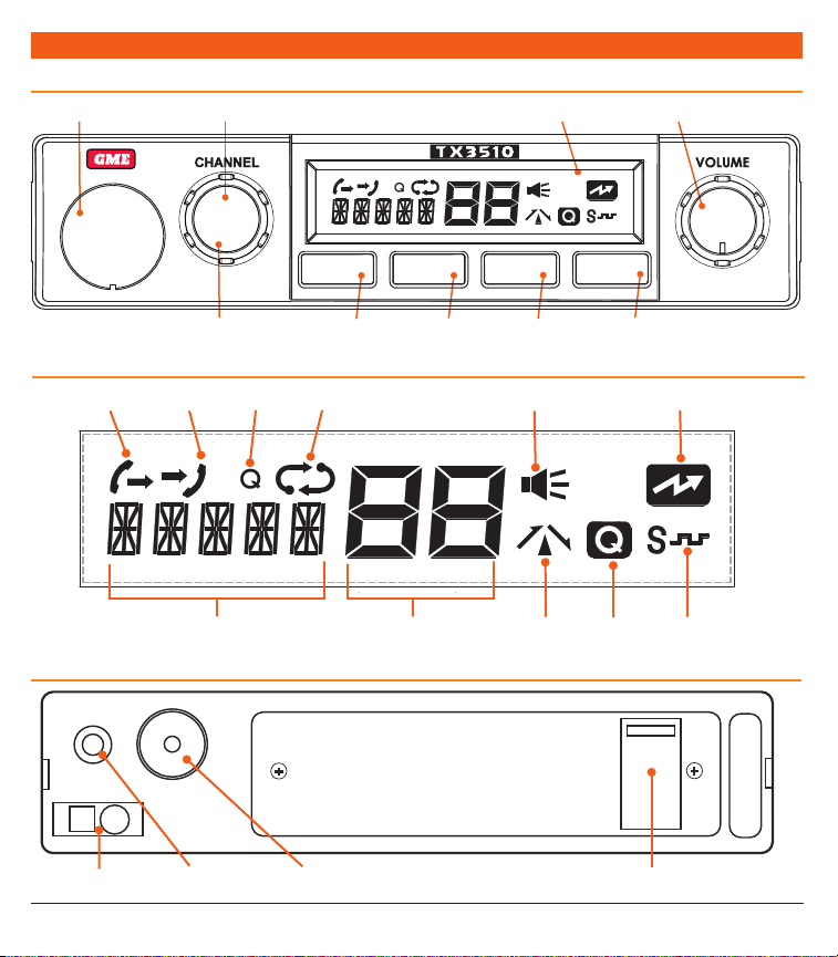
TX3510S/TX3520S FRONT PANEL CONTROLS
Front Mic Input
Channel Control
Liquid Crystal Display
Volume Control
PUSH
SQL LVL
Push for Squelch Level/
Priority Channel
PUSH
PRIORITY
MENU
F
Menu/
Function
SCAN
OS/GS
OS-GS
Scan/
QUIET
DUP
Duplex
Quiet/
SQL
ALPHA
Squelch/
Alpha
LCD PANEL
SelCall TX
SelCall RX
SelCall/Alpha Display/
Signal Meter/Battery
Quiet Tag
Scan
Channel Display
Busy
Repeater
(Duplex)
Quiet
Transmit
CTCSS/DCS
REAR PANEL
DC Power Socket
PAGE 6 I NSTRUCTION MA NUAL T X3510S/ TX3520S /T X3540S T X3510S/ TX3520S /T X3540S I NSTRUCTION MA NUAL PAGE 7
Speaker Socket
Antenna Socket Rear Microphone Socket
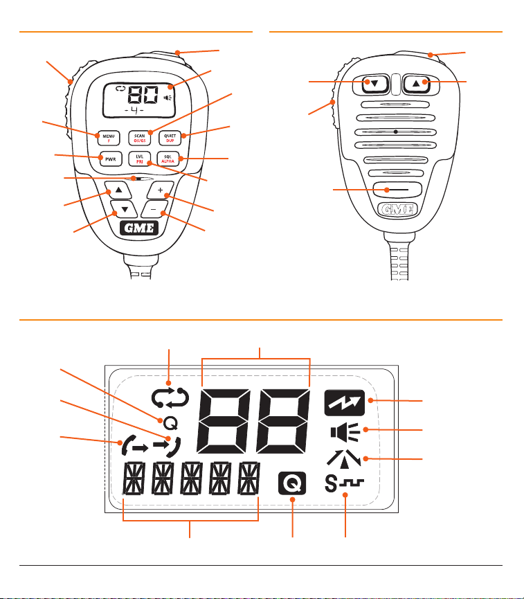
TX3540S CONTROLLER MICROPHONE TX3510S/TX3520S MICROPHONE
Push-To-Talk (PTT)
Menu/
F Key
Power Key/
Monitor
Microphone
Channel Up
Channel Down
TX3540S CONTROLLER LCD PANEL
Scan
Quiet Tag
SelCall RX
SelCall TX
Skip/Call
LCD Display
SCAN/
OS/GS
Quiet/
Duplex
Squelch/
ALPHA
Squelch level/
Priority channel
Volume Up
Volume Down
Channel Display
Channel
Down
Push To
Talk
Squelch Set /
Skip/Call
Channel
Up
Priority
Transmit
Busy
Repeater (Duplex)
SelCall/Alpha Display/Signal Meter/Battery Quiet CTCSS/DCS
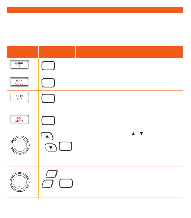
GENERAL OPERAT ION ACROSS ALL MODELS
KEYPAD FUNCTIONS
The controls on the TX3510S and TX3520S front panel and
TX3540S controller microphone all have multiple functions.
The primary functions are labelled in BLACK, while the
secondary functions are labelled in RED. To access a primary
function simply press the required key.
To access a secondary function, briefly press the F key
followed immediately by the required key.
The table below shows the control functions for all models.
TX3510S/
TX3520S
CHANNEL
PUSH PUSH
PRIORITYSQL LVL
VOLUME
TX3540S FUNCTION
MENU
F
Press and hold MENU to access the configuration menu. Press F
followed by the required key to access the secondary key-functions
labelled in
SCAN
OS/GS
QUIET
DUP
Press SCAN to toggle scanning on or off. Press F followed by
select Open Scan, Group Scan or Network Scan.
Press and hold QUIET to tag the selected channel for use with SelCall.
Press QUIET briefly to toggle the quiet mode on all channels that have
been tagged. Press F followed by
on the selected channel.
SQL
ALPHA
Press SQL briefly to toggle the Squelch on or off. Press and hold SQL to
toggle CTCSS/DCS silent mode on or off on the selected channel. Press
F
followed by
Rotate the Channel control (or press
LV L
PRI
Press the Channel control (or the LVL key) briefly to adjust the preset
Squelch level. Press
to recall the Priority channel.
F
then press and hold the Channel control (or the
Press
store the current channel as the Priority channel.
+
–
PWR
Rotate the Volume control past the click (or press the PWR key) to
switch the radio on or off.
Rotate the Volume control (or press the + or - keys) to adjust
the volume.
red
.
DUP
to toggle duplex mode on or off
ALPHA
to toggle Alpha or Numeric display modes.
or )
F
followed by the Channel control (or the
OS/GS
to change channels.
PRI
PRI
key) to
to
key)
PAGE 8 I NSTRUCTION MA NUAL T X3510S/ TX3520S /T X3540S T X3510S/ TX3520S /T X3540S I NSTRUCTION MA NUAL PAGE 9
NOTE: When using the F key to access other functions, F is
displayed to indicate that ‘Function’ mode is activated. If the
required function is not selected within 6 seconds the F key
selection will time out with a low beep and F will disappear
from the display.
A more detailed description of these key functions is included
below. These instructions describe the radio functions using the
TX3510S/TX3520S controls (with the TX3540S controls shown
in brackets).
VOLUME
Rotate the Volume control clockwise past the click (or press
the PWR key) to turn the radio on. Rotate the Volume
control left or right (or press the + or – keys) to adjust the
volume.
If no sound is heard, briefly press the SQL key to temporarily
un-mute the radio then adjust the Volume control while
listening to the background noise. When finished, briefly
press the SQL key again to re-mute the radio.
NOTE: At the minimum volume setting there is still sufficient
volume to be heard in a quiet cabin environment.
SELECTING CHANNELS
To select the required channel, rotate the Channel control
(or press the
clockwise (or press
clockwise (or press
channel is displayed on the LCD.
SQUELCH
The Squelch is used to eliminate any annoying background
noise when there are no signals present. The Squelch can
be opened or closed using the SQL key. When the Squelch
is open the receiver’s background noise can be heard and
the
receiver remains quiet while there are no signals present but
any incoming signals will override the Squelch and be heard
in the speaker.
or keys). Rotate the Channel control
) to select a higher channel or counter
) to select lower channels. The selected
symbol is displayed. When the Squelch is closed the
Adjusting the Squelch level
The Squelch sensitivity level has been factory set to provide
optimum performance under most operating conditions. If
required, the sensitivity level can be adjusted to suit
changing conditions.
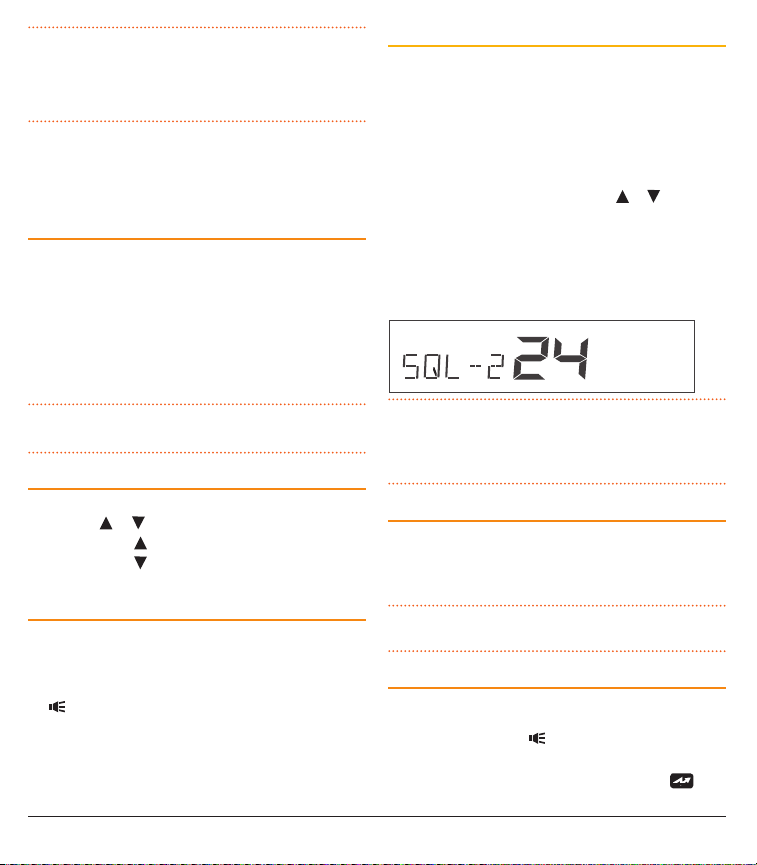
To adjust the Squelch sensitivity, briefly press the Channel
control (or LVL key). The channel display will show the
current Squelch level setting in values from SQL-1 to SQL-9.
Rotate the Channel control (or press the
the controller microphone) to change the Squelch setting.
A Squelch setting of SQL-1 allows the Squelch to open on
very weak signals whereas a setting of SQL-9 requires much
stronger signals to overcome the Squelch. After adjusting the
Squelch sensitivity, briefly press the Channel control (or LVL
key) to return to normal operation.
NOTE: The Squelch level can be actively adjusted while the
radio is scanning. This allows you to tighten the Squelch in
cases where an undesired weak or noisy signal is interrupting
the scan.
SIGNAL METER
The signal meter indicates the relative strength of the
incoming signal in numerical format. Signal strengths are
displayed on the lower left of the Channel Display in values
from 0 to 9. Signals above strength 9 are displayed as 9+.
NOTE: Refer to the Configuration Menu for other options
that can be displayed in this location.
TRANSMITTING
Prior to transmitting, always check the channel is not being
used. This can be done by listening to the channel or by
visually checking that the
meter is not indicating a signal.
To transmit, press the PTT on the microphone. The
will appear. Hold the microphone about 5-8 cm from your
icon is not visible or the signal
or keys on
icon

face and speak at a normal voice level. The microphone is
quite sensitive so it is not necessary to raise your voice or
shout. Release the PTT when you have finished talking. The
icon will disappear.
IMPORTANT: Always listen to ensure the channel is free
before transmitting.
TIME-OUT TIMER
The radio has a built-in time-out timer that automatically
limits transmissions to a maximum of 3 minutes of
continuous operation. This feature is required by the ACMA to
prevent accidental blocking of the frequency should your PTT
become jammed or be otherwise pressed accidentally. The
time-out period can be changed by your dealer.
When the time-out timer activates, the radio will beep for 5
seconds then the
symbol will flash continuously. Normal
operation will be restored once the PTT is released.
BACKLIGHTING
The Liquid Crystal Display and keys are backlit for easier
viewing at night. The backlight remains on whenever the
radio is switched on.
Adjusting the Backlighting
The backlight brightness and colour can be adjusted for
personal preference. There are three backlight settings
available.
BKLGT (Brightness setting): Provides a continuously
variable brightness adjustment from very dim to full
brightness.
COLOR (Colour setting): Provides a continuously variable
adjustment through the full colour spectrum.
White (Whiteness setting): Controls the colour
saturation of the selected colour from deep colour to white
(no colour).
To adjust the backlighting;
1. Hold the Channel control (or LVL key) to select the
Backlight mode. ‘BKLGT’ is displayed.
2. Rotate the channel control left or right (or press or
keys) to adjust the brightness.
3. Briefly press the Channel control (or LVL key) to select
the Colour setting mode. ‘COLOR’ is displayed.
4. Rotate the Channel control left or right (or press
or
keys) to adjust the colour.
5. Briefly press the Channel control (or LVL key) to select
the Whiteness setting mode. ‘WHITE’ is displayed.
6. Rotate the Channel control left or right (or press
or
keys) to adjust the colour saturation. For the deepest
colour range, reduce the WHITE setting.
To exit, press and hold the Channel control (or LVL key).
Auto-colour Mode
The radio has an automatic colour-change option that, when
activated, will cause the display colour to automatically cycle
through the available colour spectrum. The colour-change
option can be enabled temporarily as an aid to choosing
a display colour or can be set to cycle continuously as the
preferred display colour setting.
To enable the auto-colour option,
7. Hold the Channel control (or LVL key) to select the
Backlight mode. ‘BKLGT’ is displayed.
8. Briefly press the Channel control (or LVL key) to select
the Colour setting mode. ‘COLOR’ is displayed.
9. While in the colour setting mode, briefly press the MENU
key to enable or disable the auto-colour option. When
enabled, the display lighting will continuously cycle
through the available colour spectrum. When disabled the
display will hold the last selected colour.
To exit, press and hold the Channel control (or LVL key). If
auto-colour is still enabled, the display lighting will continue
to cycle through the colour spectrum until disabled using the
steps above.
NOTE: The back-light setting function will automatically
time out after 6 seconds if no further adjustments have
been made.
PAGE 10 I NSTRUCTION MA NUAL T X3510S/ TX3520S /T X3540S T X3510S/ TX3520S /T X3540S I NSTRUCTION MA NUAL PAGE 11
BANDWIDTH FILTER SETTINGS
To accommodate the blending of newer 80 channel
narrowband UHF radios with the original 40 channel
wideband radios, your radio has been fitted with two user
selectable receiver bandwidth filters. While the use of
either filter will provide superb receive audio, selecting the
wideband filter while on channels 1-40 will further increase
your receiver’s tolerance to older 40 channel wideband
radios that might otherwise sound over-modulated or
mildly distorted. Select the narrowband filter to improve
the selectivity of the receiver to provide greater resistance
to interference from older 40 channel wideband radios
operating on adjacent channels.
To select the desired filter
1. Press and hold MENU to enter the menu.
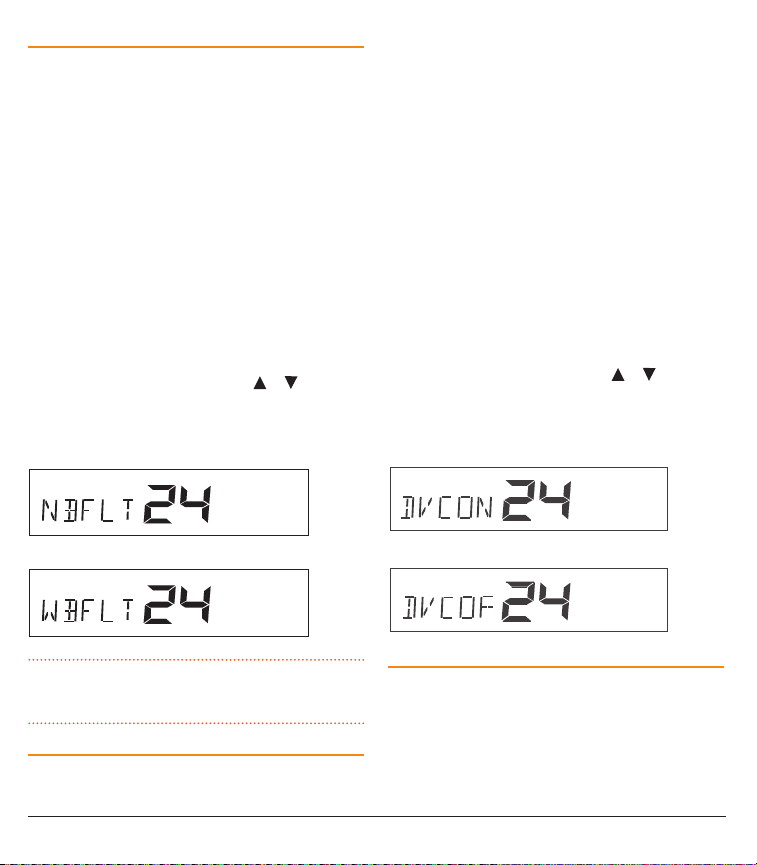
2. Press MENU repeatedly until ‘NBFLT’ (Narrowband Filter)
or ‘WBFLT’ (Wideband Filter) is displayed.
3. Rotate the Channel control (or press
make the desired selection.
When finished briefly press the PTT to exit the menu.
or keys) to
Narrowband filter selected
differences in received audio volume between stations.
Generally users have compensated for this by adjusting
the Volume control for each incoming signal. With the
introduction of 80 channel narrowband transmissions that
use lower levels of modulation, the diversity in received audio
volume is likely to increase further.
Your radio is able to automatically compensate for these
variations in received audio level by utilising a Dynamic
Volume Control. When activated, this feature automatically
compensates for variations in received audio level resulting in
a constant audio output level to the speaker.
To activate the Dynamic Volume Control
1. Press and hold MENU to enter the menu.
2. Press MENU repeatedly until ‘DVCOF’ (Dynamic Volume
Control Off) or ‘DVCON’ (Dynamic Volume Control On) is
displayed.
3. Rotate the Channel control (or press
make the desired selection.
When finished briefly press the PTT to exit the menu.
or keys) to
Dynamic Volume Control ON
Wideband filter selected
NOTE: The wideband receiver filter setting is only applied
to channels 1 – 40. Channels 41 – 80 always use the
narrowband filter.
DYNAMIC VOLUME CONTROL (DVC)
The modulation level of signals heard on the UHF CB band
has always varied considerably resulting in noticeable
Dynamic Volume Control OFF
VOICE SCRAMBLER
Your radio incorporates a simple voice scrambler using band
inversion. The scrambler is compatible with the majority
of scramblers used by other manufacturers, allowing you
to enjoy scrambled communications with owners of nonGME radios. Once the scrambler has been activated your
transmission and reception will only be intelligible to others
using the same scrambler technology.
To enable or disable the voice scrambler
1. Press and hold MENU to enter the menu.
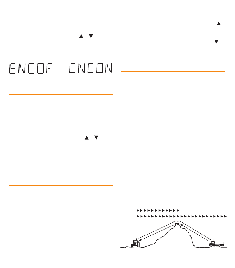
2. Press MENU repeatedly until ‘ENCOF’ (Encoder Off) or
‘ENCON’ (Encoder On) is displayed.
3. Rotate the Channel control (or press
or keys) to
make the desired selection. Select ‘ENCON’ to activate
the scrambler or ‘ENCOF’ to disable it.
When finished briefly press the PTT to exit the menu.
2. Press MENU repeatedly until ‘SSTxx’ is displayed where xx
=ONorOF.
3. Rotate the Channel control to the right (or press the
key) to enable the Silent Squelch Tail. ‘SSTON’ will be
displayed and the Squelch Tail will become silent.
4. Rotate the Channel control to the left (or press the
key) to disable the Silent Squelch Tail. ‘SSTOF’ will be
displayed and the Squelch Tail will be restored.
When finished, briefly press the PTT to exit.
REPEATERS AND DUPLEX MODE
Scrambler Encoder OFF
Scrambler Encoder ON
BEEP TONE VOLUME
The Key Beeps provide audible feedback whenever the keys
are pressed. You can adjust the volume of the key beeps
as follows.
1. Press and hold MENU to enter the menu.
2. Press MENU repeatedly until ‘BEEPx’ is displayed (where
x is a value from 0 – 9).
3. Rotate the Channel control (or press the
or keys)
to adjust the Beep volume from 0 – 9.
• BEEP1=minimum
• BEEP9=maximum
• BEEP0=Off
When finished, briefly press the PTT to exit.
SILENT SQUELCH TAIL
The Squelch Tail is the short burst of noise that is heard in
the speaker at the end of a transmission just before the
Squelch closes.
To some it is a reassuring confirmation that it is their turn to
transmit but in some applications it may be an annoyance
especially when listening through an earpiece or headphones.
The Silent Squelch Tail function removes this Squelch Tail,
reducing it to a faint click as the Squelch closes.
To enable or disable the Silent Squelch Tail
1. Press and hold MENU to enter the menu.
PAGE 12 I NSTRUCTION MA NUAL T X3510S/ TX3520S /T X3540S T X3510S/ TX3520S /T X3540S I NSTRUCTION MA NUAL PAGE 13
Duplex operation allows the radio to transmit on a different
frequency to that which it receives. This allows operation
through repeater stations.
A repeater station consists of a linked transmitter/receiver
combination installed in a prominent location. The repeater
is designed to receive signals on a designated channel and
retransmit them on another channel. Repeaters are usually
mounted on hills or tall buildings. The increase elevation
greatly improves both the receiving and transmitting range of
the repeater allowing it to receive and retransmit signals to
radios that would otherwise be out of range of each other.
Normally, UHF radios transmit and receive on the same
frequency – known as Simplex operation. However to
communicate through repeaters, your radio must be able to
transmit and receive on different channels – otherwise known
as Duplex operation. Your radio is fitted with a Duplex key to
allow you to operate through repeaters.
The Duplex function can only be selected on channels 1 – 8
and 41 – 48 as these are the channels that have been
allocated for repeater use. When Duplex is selected, your
radio receives on the selected channel (e.g. CH 1) but
transmits 30 channels higher (CH 31). The repeater hears your
signal on CH 31 and retransmits it on CH 1 for others to hear.
SIMPLEX
REPEATER
OPERATION
CHANNEL 1
CHANNEL 31
VEHICLE
VEHICLE
CHANNEL 31
CHANNEL 1
REPEATER
STATION
 Loading...