

Page 1
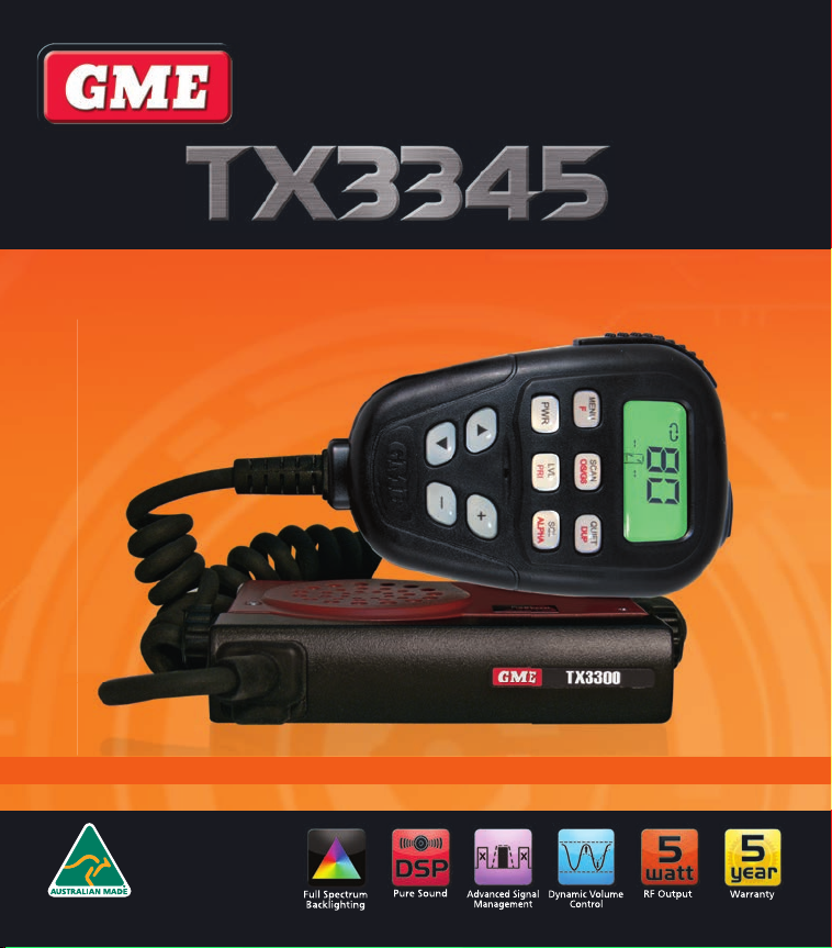
5 watt super compact UHF CB remote LCD mic
INSTRUCTION MANUAL
Page 2

CONTENTS
ACCESSORIES SUPPLIED .................................................3
IMPORTANT INFORMATION ............................................3
EMERGENCY CHANNELS................................................3
TELEMETRY CHANNELS ..................................................3
FEATURES ......................................................................4
GENERAL OPERATION ....................................................5
MC524B Controller Microphone ..............................5
Display....................................................................5
Function Keys ..........................................................5
Volume Key .............................................................5
Transmitting ............................................................6
Squelch ...................................................................6
Squelch Sensitivity ...................................................6
Menu .....................................................................7
Backlighting ............................................................7
Key Beeps ...............................................................7
Signal Meter/Battery Meter .....................................8
Priority Channel ......................................................8
Duplex Operation ....................................................8
Dynamic Volume Control (DVC) ...............................9
CTCSS & DCS .................................................................9
Choosing the CTCSS or DCS Tone ............................9
To select a CTCSS or DCS Tone ..............................10
Enabling CTSS/DCS on a Channel ..........................10
Disabling CTCSS/DCS on a Channel .......................10
MONITORING THE CHANNEL ........................................10
SCANNING ..................................................................11
Scan Groups .........................................................11
Selecting a Scan Group .........................................11
Programming Scan Channels ................................11
OPEN SCAN MODE ....................................................12
GROUP SCAN MODE ..................................................12
Auto Skip .............................................................13
Quick Channel Select ...........................................13
Using two Group Scan or two Open Scan Modes ..13
SELECTIVE CALLING ....................................................13
SelCall Indentification Number (IDENT) .................14
SelCall Ident Labels ..............................................14
The Quiet Mode ...................................................14
USING SELCALL ..........................................................14
Entering a SelCall Ident ........................................14
Call Acknowledge ................................................15
SelCall Memories .................................................15
Labelling your SelCall Idents .................................15
Receiving SelCalls ................................................16
Quiet Mode .........................................................16
Scanning in the Quiet Mode .................................17
GROUP CALLING.........................................................18
INSTALLATION ............................................................19
Antenna Installation .............................................19
DC Power Connection ..........................................21
High Voltage Warning...........................................22
Antenna Connection ............................................22
CTCSS TONE FREQUENCY CHART ................................23
DCS TONE CHART........................................................24
UHF CB OPERATING FREQUENCIES .............................25
SPECIFICATIONS .........................................................26
SC CONTRACT WARRANTY AGAINST DEFECTS ............27
PAG E 2 INSTRUCTION MANUAL TX3345
Page 3

ACCESSORIES SUPPLIED
• Main Radio Unit
• Mounting Cradle
• Instruction Manual
• MC524B LCD
Microphone
• Microphone Clip
• DC Lead
• Screw Pack
If any items are missing or
damaged, please contact
your
retailer or place of
purchase
.
IMPORTANT INFORMATION
CONCERNING 80 CH UHF CB RADIO
The use of the Citizen Band radio service is licensed in
Australia by the ACMA radio communications (Citizens
Band radio stations) Class Licence and in New Zealand by
the Ministry of Economic Development New Zealand (MED).
A General User Radio Licence for Citizens Band radio
and operation is subject to conditions contained in those
licences.
The class licence for users and equipment operating in the
CB/PRS 477 MHz band has been amended. This radio meets
the new 80 channel standard.
In simple terms the same amount of spectrum is available;
however, radio transceivers can now operate in a narrower
bandwidth and hence use less spectrum. These radios are
generally referred to as narrowband or 12.5 kHz radios.
By using 12.5 kHz channel spacing instead of 25 kHz, the
40 channels originally allocated can now be expanded to
80 channels thereby doubling the channel capacity and
relieving congestion in the UHF CB/PRS band.
Original 40 channel wideband Radios will continue to
operate on the original 40 channels, however they will not
be able to converse on the newer channels 41 – 80. The
newer narrowband radios will be able to converse with all
older 40 channel wideband radios on all channels 1 to 40
as well as the newer channels allocated from 41 to 80.
The mixing of narrowband and wideband radios in the
same spectrum can cause some possible operating issues of
interference and varying levels of received volume.
TX3345 INSTRUCTION MANUAL PAG E 3
POSSIBLE ISSUES
When a new narrowband radio receives a transmission from an
older wideband radio the speech may sound loud and distorted
– simply adjust your radio volume for best performance.
When an older wideband radio receives a signal from a new
narrowband radio, the speech may sound quiet – simply
adjust your radio volume for best performance.
There can be interference from a nearby transmitting radio if
it is using a channel adjacent to the channel you are listening
to. Simply try going up or down a few channels from the
currently selected channel. The above situations are not a
fault of the radio but a symptom of operating wideband and
narrowband radios in the same bandwidth. This possible
interference will decrease over time as the population of
wideband radios ages and decreases.
Further information and updates are available from the
Australian Communications and Media Authority (ACMA) at:
www.acma.gov.au and the Ministry of Economic Development
(MED), Radio Spectrum Management at: www.rsm.govt.nz
EMERGENCY CHANNELS
The ACMA has allocated channels 5/35 for emergency use
only. Channel 5 is the primary Simplex Emergency Channel.
Where a Channel 5 repeater is available, you should select
Duplex on CH 5.
NOTE: Channel 35 is the input channel for the Channel 5
repeater therefore Channel 35 should also not be used for
anything other than emergency transmissions.
TE LEMETRY CHANNELS
ACMA regulations have allocated Channels 22 and 23
for telemetry-only applications and have prohibited the
transmission of speech on these channels. Consequently the
TX3345 has a transmit inhibit applied to channels 22 and 23.
In the event additional telemetry/telecommand channels
are approved by the ACMA, these channels shall be added
to those currently listed where voice transmission is
inhibited. Currently transmissions on Channels 61, 62 and
63 are also inhibited and these channels are reserved for
future allocation.
Page 4

FEATURES
TRANSMIT (TX)
Individually Programmable DUPLEX function: User selectable for only those individual channels in your area that have
repeaters, leaving the others free for use as extra simplex channels.
SIGNAL PROCESSING
Digital Signal Processing: Measures, filters and compresses
digital format. Allows advanced RF and audio processing techniques to be applied to maximise the radio’s performance.
Advanced Signal Management (ASM): Identifies interference caused by strong local signals on adjacent channels and
prevents it from opening your Squelch.
Dynamic Volume Control (DVC): Automatically compensates for variations in received audio level resulting in a constant
audio output level to the speaker
SCANNING AND MEMORY FUNCTIONS
Microprocessor Controlled Frequency Synthesiser: Allows user programmable control of scanning, channel memories
and selected feature options
Programmable Scan Function: Scans the programmable UHF CB channels with both Group and Open scan functions
available.
Priority Channel: A user programmable Priority Channel feature allows your working or local repeater Channel to be
instantly recalled at the press of a button.
PRIVACY FUNCTIONS
In-Built SelCall: Selective Calling with five digit ANI and fully user-adjustable 5 tone transmitted SelCall Ident. Also allows
naming of Idents for easier caller identification.
Quiet Mode: Selectable on individual channels, Quiet mode prevents incoming signals from being heard on selected
channels unless preceded by your SelCall code.
CTCSS & DCS: A built-in Continuous Tone Coded Squelch System and Digital Coded Squelch option provides quiet channel
operation.
PHYSICAL PROPERTIES
Overvoltage Protection: Special overvoltage detection circuitry protects the radio and warns of excessive voltage
conditions by flashing the display.
USER CONTROLS AND INTERFACE
Controller Microphone: Complete control of the radio from the microphone simplifies installation.
High Contrast Liquid Crystal Display: Fully detailed LCD provides a visual indication of the selected channel and all
selected functions at a glance. Backlit for viewing at night.
.
.
standard analogue audio signals and converts them into
PAG E 4 INSTRUCTION MANUAL TX3345
Page 5
GENERAL OPERATION
+
+
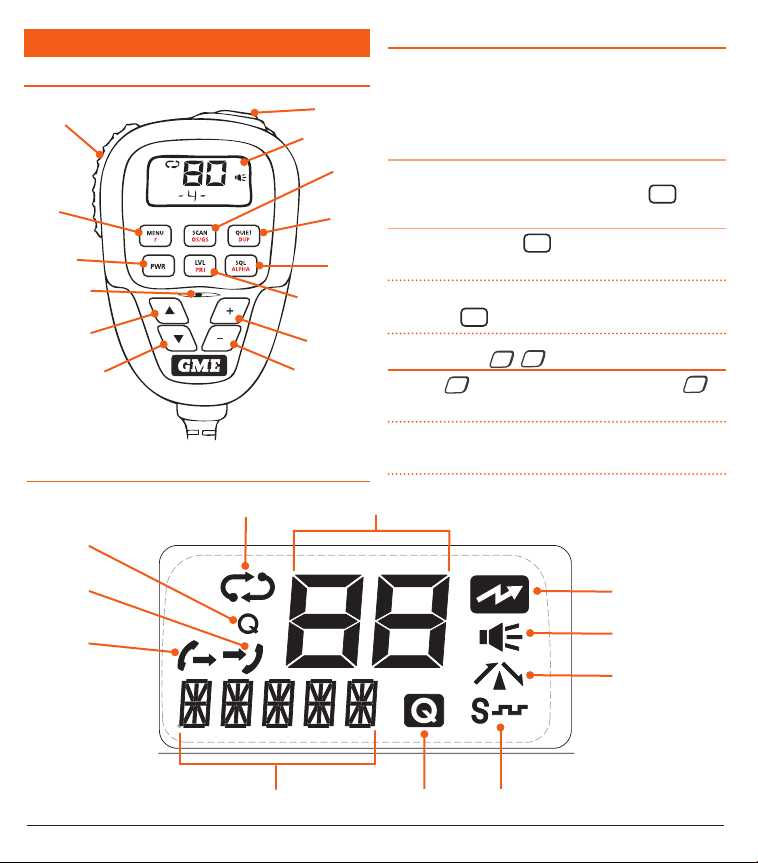
MC524B MICROPHONE/CONTROLLER
Push-To-Talk (PTT)
Menu/
F Key
Power Key/
Monitor
Microphone
Channel Up
Channel Down
DISPLAY
Scan
Quiet Tag
Skip/Call
LCD Display
SCAN/
OS/GS
Quiet/
Duplex
Squelch/
ALPHA
Squelch level/
Priority channel
Volume Up
Volume Down
Channel Display
FUNCTION KEYS
There are several keys beneath the microphone controller’s
display that have dual functions. Their primary functions are
printed in black and their secondary functions are printed
in red.
To access the primary (black) functions
Press the key with the required function labelled in black.
e.g. To control the Squelch, briefly press the
SQL
ALPHA
key.
To access the secondary (red) functions
Press the Function key
MENU
followed immediately by the
F
key with the required function labelled in red.
NOTE: If the secondary key is not pressed within 10
seconds the
VOLUME KEY
Press the + key to increase the volume and the
MENU
key selection will time-out.
F
–
+
–
key to decrease the volume.
NOTE: At minimum volume setting there is still sufficient
volume to be heard in a quiet cabin environment.
SelCall RX
SelCall TX
Transmit
Busy
Repeater (Duplex)
SelCall/Alpha Display/Signal Meter/Battery Quiet CTCSS/DCS
TX3345 INSTRUCTION MANUAL PAG E 5
Page 6
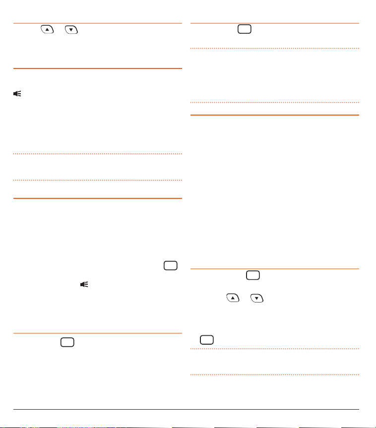
Selecting Channels
Press the or keys to step upwards or downwards
one or more channels. Press and hold to advance through
the channels at a faster rate.
TRANSMITTING
Prior to transmitting, always check the channel is not being
used. This can be done by either listening or by checking the
indicator is not lit.
To transmit, press the PTT button. Hold the microphone
about 5-8 cm from your face and speak at a normal voice
level. The microphone is quite sensitive so it is not necessary
to raise your voice or shout. Release the PTT when you have
finished talking.
IMPORTANT: Always listen to ensure the channel is free
before transmitting
.
SQUELCH
The Squelch is used to eliminate the background noise
when there are no signals present. The TX3345 features
a preset Squelch system. The Squelch sensitivity has been
factory set to provide optimum performance in most
environments, however the sensitivity can be altered by the
user if required, to suit varying environmental situations.
The Squelch can be opened or closed by pressing the
SQL
ALPHA
key. When the Squelch is open, the receiver’s background
noise can be heard and
is displayed. When the Squelch
is closed, the receiver remains quiet when there are no
signals present but an incoming signal will override the
Squelch and be heard in the speaker.
To open the Squelch
Briefly press the
SQL
key. A low beep will be heard. If
ALPHA
there are no signals present you will hear the receiver’s
background noise.
To close the Squelch
SQL
Briefly press the
ALPHA
key again. A high beep will be heard
and the receiver will become quiet.
NOTE: If an incoming signal is very weak and is close to the
minimum Squelch level, it may become broken or ‘chopped’
by the Squelch action. To prevent this, simply open the
Squelch to allow the signal to be heard clearly. Alternatively
you can reduce the Squelch sensitivity as described below.
SQUELCH SENSITIVITY
The sensitivity of the Squelch to incoming signals can be set
to suit your operating environment. In quiet rural locations
a low setting will allow the weakest signals to be received
while still keeping the radio quiet between transmissions. In
city locations, a higher setting might be needed to ensure
the Squelch remains closed when subjected to the higher
interference levels often encountered in high density areas.
The TX3345 has nine (9) preset Squelch sensitivity settings
labelled SQL-1 to SQL-9. The minimum Squelch setting
(SQL-1) is the most sensitive and will allow the Squelch to
open on very weak signals. SQL-9 is the maximum setting,
requiring very strong signals to open the Squelch. The
factory default is SQL-3 which generally provides reliable
Squelch operation for most applications.
To adjust the Squelch sensitivity
1. Briefly press the
LVL
key. ‘SQL-X’ will be displayed
PRI
where X is a value from 1 to 9.
2. Press the
or keys to change the Squelch
value. The Squelch adjustment is live allowing you to
adjust the Squelch to suit your current environment.
3. When your adjustment is complete, briefly press the
LVL
key to return to normal operation.
PRI
NOTE: The Squelch level can also be adjusted within the
Menu.
PAG E 6 INSTRUCTION MANUAL TX3345
Page 7
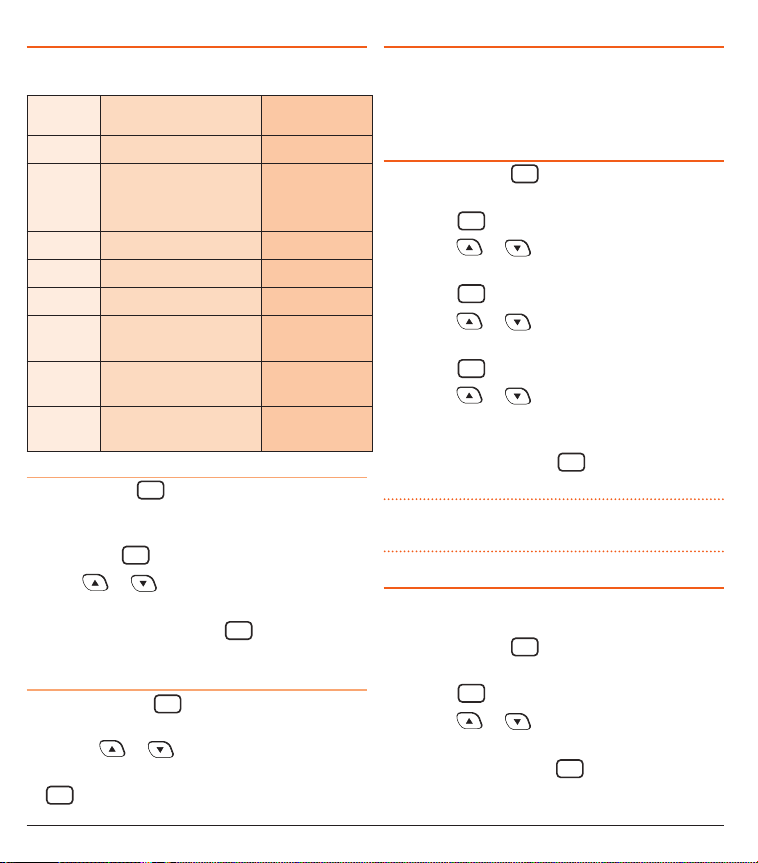
MENU
The Menu provides a convenient way to customise your
radios settings. The following Menu options are available
MENU
ITEM
FUNCTION AVAILABLE
SETTINGS
SQL Adjust Squelch Level SQL--1 TO SQL--9
CTCSS Set CTCSS or DCS Code CTCOF
CTC01 -> CTC50
DC001 -> DC104
LIGHT Adjust Display Brightness See Display
COLOR Adjust Display Colour See Display
WHITE Adjust Colour Saturation See Display
S-METER/
BATT
BEEP Adjust Key Beep-Tone
DVC Activate/ Deactivate the
Display S-Meter or Battery
Voltage on the LCD
Volume
S-MET / BATT
VOL--0 ->
VOL--9
DVCOF / DVCON
Dynamic Volume Control
To use the Menu
Press and hold the
MENU
key until the radio beeps. ‘SQL’
F
will be displayed indicating the first Menu item (Squelch
setting mode) is selected.
Briefly press the
Press the
MENU
key to cycle through the Menu items.
F
or keys to adjust the selected Menu
item.
When finished, press and hold the
MENU
key to exit the
F
Menu or wait until the Menu times out.
To adjust the Squelch sensitivity from the Menu
1. Press and hold the
MENU
key for several seconds. The
F
radio will enter Menu mode and ‘SQL’ will be displayed.
2. Press the
3. When your adjustment is complete, briefly press the
MENU
F
or keys to adjust the Squelch value.
key to return to normal operation.
BACKLIGHTING
The Liquid Crystal Display and keys are backlit for easy
.
viewing at night. The backlight remains on while the radio
is switched on. The backlighting brightness, colour and
saturation are all fully adjustable for personal preference.
To adjust the Backlighting:
1. Press and hold the
MENU
key for several seconds. The
F
radio will enter Menu mode and ‘SQL’ will be displayed.
2. Press the
3. Press the
MENU
key repeatedly until ‘LIGHT’ is displayed.
F
or keys to adjust the backlight
brightness.
4. Press the
5. Press the
MENU
key briefly. ‘COLOR’ is displayed.
F
or keys to adjust the backlight
colour. The full spectrum of colours is available.
6. Press the
7. Press the
MENU
key briefly. ‘WHITE’ is displayed.
F
or keys to adjust the whiteness or
colour saturation of the selected backlight colour from
full colour to white (no colour).
8. To exit, press and hold the
MENU
key or wait for the
F
Menu to time out.
TIP: For the deepest colour range, reduce the WHITE
setting.
KEY BEEPS
The key beeps act as confirmation of your key presses.
You can adjust the volume level of the beeps as follows.
1. Press and hold the
MENU
key for several seconds. The
F
radio will enter Menu mode.
2. Press the
3. Press the
MENU
key repeatedly until ‘BEEP’ is displayed.
F
or keys to adjust the beep volume
from 0 (silent) to 9 (loud).
4. To exit, press and hold the
MENU
key or wait for the
F
Menu to time out.
TX3345 INSTRUCTION MANUAL PAG E 7
Page 8
SIGNAL METER/BATTERY METER
The TX3345 includes a digital signal strength meter that
shows the relative strength of incoming signals on the
display. The meter displays signal strengths in values
from 0 (very weak) to 9 (very strong). Signals that exceed
strength 9 are shown as 9+
The TX3345 can also be set to display a battery meter
instead of the signal meter. The battery meter displays the
voltage of the connected power source with a resolution of
0.1 V. The Signal Meter is selected by default.
To switch between Signal Meter and Battery Meter:
MENU
1. Press and hold the
key for several seconds. The
F
radio will enter Menu mode.
2. Press the
MENU
key repeatedly until ‘S-MET’ (S Meter) or
F
‘BATT’ (Battery) is displayed.
3. Press the
or keys to select the required
option.
4. To exit, press and hold the
MENU
key or wait for the
F
Menu to time out.
PRIORITY CHANNEL
The Priority Channel feature allows you to store one
channel as a Priority Channel that can be instantly recalled
at the press of a key. This can be used to provide instant
access to your working channel or your local repeater
channel.
To store a Priority Channel
1. Select the required channel.
2. Briefly press the
LVL
key. The selected channel will flash followed by
PRI
MENU
key then press and hold the
F
a high beep as the channel is stored.
To recall a Priority Channel
Briefly press the
MENU
key then briefly press the
F
LVL
PRI
key. The radio will switch straight to the selected Priority
Channel. Any active functions (such as Scanning or Quiet)
will be cancelled.
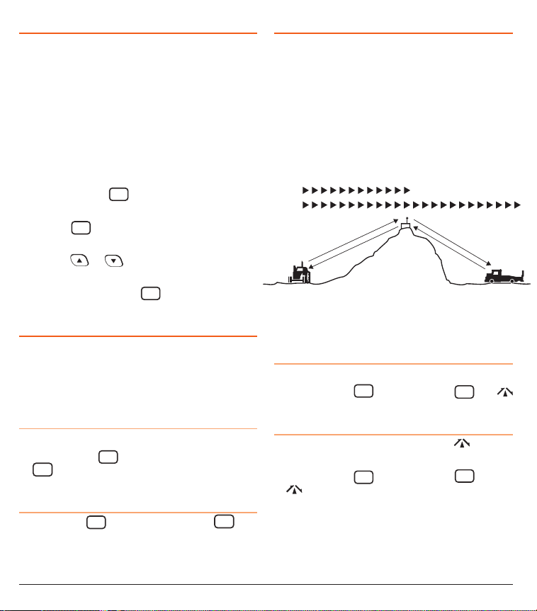
DUPLEX OPERATION
Duplex operation allows the radio to transmit on a different
frequency to that which it receives allowing operation
through repeater stations. Repeaters automatically
re-transmit your signal over a wider area, providing greatly
increased range.
Duplex operates only on channels 1-8 and 41-48. When
duplex is selected on these channels, the radio receives on
that channel but actually transmits 30 channels higher.
Simplex/Duplex Range Comparison
Simplex
Repeater
operation
Channel 1
Channel 31
Channel 1
Repeater
Station
Channel 31
Vehicle
The TX3345 allows you to select Duplex operation individually on each channel.
To select Duplex:
1. Select the required channel 1-8 or 41-48.
2. Briefly press the
MENU
F
key then press the
QUIET
DUP
key.
will appear on the display accompanied by a high beep.
To remove Duplex from a channel
1. Select the required channel 1-8 or 41-48. will be
visible on the display.
2. Briefly press the
MENU
key then press the
F
QUIET
DUP
key.
will disappear from the display accompanied by
a low beep.
Vehicle
PAG E 8 INSTRUCTION MANUAL TX3345
Page 9
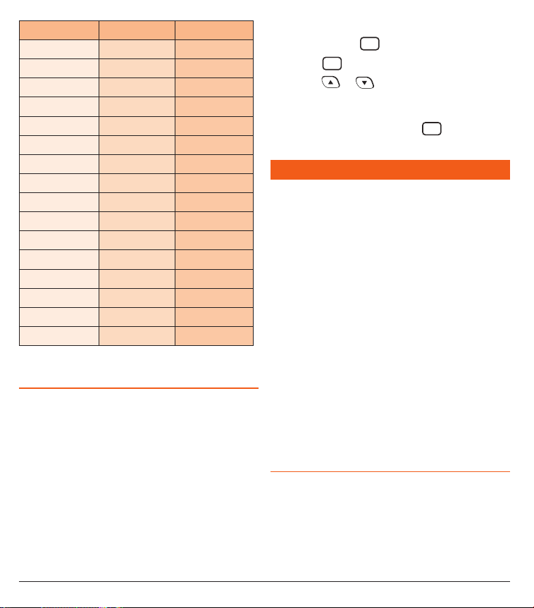
Channel Selected Receive Channel Transmit Channel
1 1 31
2 2 32
3 3 33
4 4 34
5* 5* 35*
6 6 36
7 7 37
8 8 38
41 41 71
42 42 72
43 43 73
44 44 74
45 45 75
46 46 76
47 47 77
48 48 78
*Emergency Channel only
DYNAMIC VOLUME CONTROL (DVC)
The modulation level of signals heard on the UHF CB band
often vary considerably resulting in noticeable differences in
received audio volume between stations. In the past, users
have compensated for this by adjusting the volume control
for each incoming signal. However with the introduction
of 80 channel narrowband transmissions, the diversity
in received audio volume has increased even further.
The TX3345’s Dynamic Volume Control is designed to
automatically compensate for these variations in received
audio level to provide a constant audio output level to the
speaker.
To select the Dynamic Volume Control:
1. Press and hold the
2. Press the
3. Press the
MENU
key to enter the Menu.
F
MENU
key repeatedly until DVCxx is displayed.
F
or keys to select DVCOF (Dynamic
Volume Control Off) or DVCON (Dynamic Volume
Control On).
4. When finished, press and hold the
MENU
key or wait for
F
the Menu to time out.
CTCSS & DCS
CTCSS (Continuous Tone Coded Squelch System) and DCS
(Digitally Coded Squelch) are Squelch quieting systems that
allow several groups of users to share the same channel
without disturbing each other. There are three optional tone
sets available comprising 38, 50 or 104 codes.
CTCSS and DCS systems apply a continuous low-level
low frequency tone to your transmission with a matching
decoder at the receiver to control your radio’s Squelch. With
CTCSS or DCS enabled, the channel remains quiet to all
incoming signals unless they carry the correct tone. When a
transmission with the correct tone is received, the Squelch
opens and remains open for as long as the signal is present.
When the transmission ends, the channel becomes quiet
again. Transmissions that do not use the correct tone will
not be heard.
The TX3345 allows CTCSS or DCS to be enabled or disabled
on selected channels and the CTCSS/DCS tone you select
will be used for all CTCSS/DCS enabled channels in your
radio.
CHOOSING THE CTCSS OR DCS TONE
Choosing which tone to use will probably be dependent on
the other radios you talk to. If you talk to others outside
your group who already use CTCSS or DCS tones, you will
need to select the tone set and frequency that matches
theirs. The TX3345 supports CTCSS 50 and CTCSS 38 tone
sets as well as 104 DCS tones. If the users you talk to don’t
currently use CTCSS or DCS you can make your own choice.
TX3345 INSTRUCTION MANUAL PAG E 9
Page 10

There is no difference in performance between the different
tone sets.
If using CTCSS you can chose either the 50 tone set or the
38 tone set. GME radios traditionally use the 50 tone set,
however the 38 tone set is also included for compatibility
with other radios.
To switch between the 50 and the 38 tone / set:
1. Switch the radio off.
2. Press and hold the
SQL
key while switching the radio
ALPHA
on again.
3. CTC50 or CTC38 will be displayed briefly to indicate the
selected tone set.
TO SELECT A CTCSS OR DCS TONE
NOTE: When selecting tones, CTCSS tones are prefixed with
‘CTC’ and DCS tones are prefixed with ‘DC’. Please refer to
the CTCSS/DCS table later in this manual for a list of tone
numbers and their associated frequencies.
MENU
F
1. Press and hold the
2. Briefly press the
key until the radio beeps.
MENU
key repeatedly until ‘CTCxx’ or
F
‘DCxxx’ is displayed (where xx represents a tone number
in the CTCSS or DCS Tone Frequency Chart).
3. Press the
or keys to scroll through the tone
list and select the required CTCSS or DCS tone. CTCSS
tones are grouped in the lower half of the list while DCS
tones are grouped above the CTCSS tones.
4. If you wish to view the CTCSS frequency or DCS tone
instead of the table number, briefly press the
To return to the table code, briefly press the
key again.
LVL
key.
PRI
LVL
PRI
5. To disable CTCSS or DCS tones altogether scroll to the
bottom of the list and select ‘CTCoF’.
6. To store the setting, press and hold the
MENU
F
key until
the radio beeps or wait for it to time out.
ENABLING CTCSS/DCS ON A CHANNEL
Once a CTCSS or DCS tone has been selected, it can be
enabled on individual channels.
1. Press the
or keys to select the required
channel.
2. Press and hold the
(CTCSS) or (DCS) will appear indicating
and the
SQL
key. A high beep will be heard
ALPHA
that the ‘Silent’ mode has been activated on that
channel.
You may activate CTCSS or DCS on as many channels
as you wish except channel 5 which is designated for
emergency use.
DISABLING CTCSS/DCS ON A CHANNEL
1. Press the or keys to select the required
channel. The
or icon will be visible indicating
that the ‘Silent’ mode is currently enabled on that
channel.
SQL
2. Press and hold the
and the
ALPHA
key. A low beep will be heard
or icon will disappear indicating that the
‘Silent’ mode has been disabled on that channel.
MONITORING THE CHANNEL
It is useful to be able to temporarily open your radio’s
Squelch to allow you to listen for signals from other CTCSS/
DCS users outside your group. Because their CTCSS/DCS
tone is different to yours, your Squelch would normally
remain closed, preventing you from hearing them. You can
SQL
use the
key to open the Squelch and listen to the
ALPHA
channel to check that it is clear before transmitting. This will
help prevent you from accidentally transmitting over the top
of others.
To monitor the channel
Briefly press the
you will hear the usual hiss of an empty channel. Press
SQL
ALPHA
the
SQL
key. If there are no signals present,
ALPHA
key again to restore the Squelch to its previous
setting.
PAG E 10 INSTRUCTION MANUAL TX3345
Page 11

SCANNING
The TX3345 has a SCAN function that allows groups of user
programmable channels to be scanned for signals. Channels
can be scanned at 20 channels per second. When a signal
is found, scanning will pause on that channel to allow the
signal to be heard, then resume scanning when the channel
is clear again.
SCAN GROUPS
The TX3345 features two scan groups by default - Open
Scan and Group Scan.
Open Scan
Allows any of the installed channels to be scanned for
activity. If a busy channel is found, scanning will pause to
allow the signal to be heard. Once the channel has been
clear for 5 seconds, scanning will resume automatically.
1 - 2 - 3 - 4 - 5 - 6 - 7 - 8
e.g. Scanning channels 1-8 in Open Scan.
Group Scan
Also allows any of the installed channels to be scanned for
activity, but in addition, it inserts your Priority Channel into
the scan sequence. This means that your Priority Channel
will be monitored regularly while scanning to ensure that
no calls are missed. Any signals received on your Priority
Channel will take precedence over any signals received on
the other channels.
1 - 2 - 3 - 4 - 20 - 5 - 6 - 7 - 8 - 20
e.g. Scanning channels 1-8 with Priority Channel 20 in
Group Scan.
SELECTING A SCAN GROUP
PROGRAMMING SCAN CHANNELS
Your TX3345 is supplied with all 80 UHF CB channels
programmed into the Open Scan memory. Any channels
not needed, can be removed if required. The Group Scan
memory is empty by default and you will need to add
channels to it before use.
To add or remove channels from either scan
memory
1. Ensure that the radio is not already scanning. If it is,
briefly press the
SCAN
key to cancel the scan function.
OS/GS
2. Ensure you have the required scan group selected (Open
Scan or Group Scan.
3. Select the required channel by using the
or
keys
• If
is visible to the right of the channel number, the
selected channel is already in the scan memory.
• If
is not visible, then the selected channel is not in
the memory.
4. To add or remove the selected channel, press and hold
SCAN
the
key for a few seconds until a beep is heard.
OS/GS
5. Repeat step 3 & 4 to add or remove other channels in
the scan memory.
To start scanning
To begin scanning, briefly press the
will be heard, the
icon will animate on the display and
SCAN
key. A high beep
OS/GS
the radio will begin scanning. In addition the selected scan
group will be displayed below the channel number.
NOTE: If there is only one channel programmed into the
Open Scan memory or none in the Group Scan memory, a
long low beep will be heard when you press the
SCAN
OS/GS
key
and the command will be ignored.
To pre-select a scan group
The radio is initially set to Open Scan mode. To toggle
between Scan Groups, press the
SCAN
key. ‘Open’ or ‘Group’ will be displayed briefly to
OS/GS
MENU
key followed by the
F
confirm your selection.
TX3345 INSTRUCTION MANUAL PAG E 11
To stop scanning
To cancel the scan, briefly press the
will be heard and the
icon will disappear from the
display.
SCAN
key. A low beep
OS/GS
Page 12

OPEN SCAN MODE
Before scanning, select your preferred working channel
using the
default channel your radio will transmit on when the PTT is
pressed while scanning.
Scanning in Open Scan Mode
If a busy channel is found, the scan will pause on the
channel to allow you to hear the signal and will resume
scanning once the channel has been clear for 5 seconds.
While the scan is paused, the
animate on
the display to indicate that the scan function is still active.
To talk on your working channel while the radio is scanning,
simply press the PTT. Scanning will pause and your radio
will switch to your working channel allowing you to transmit
and receive on that channel. When your conversation has
finished and the channel has been clear for 5 seconds,
scanning will resume.
If the scan pauses on any busy channel and you wish to talk
on that channel, simply wait for a break in the conversation
and press the PTT. The busy channel now becomes your
working channel, replacing your previous working channel.
Once your conversation has finished and the channel has
been clear for 5 seconds, scanning will resume.
If you need to use your Priority Channel while your radio
is scanning (perhaps for an urgent call or an emergency),
briefly press the
radio will jump straight to the Priority Channel and the Scan
mode will be cancelled.
If you wish to remain on a busy channel, briefly press the
SCAN
OS/GS
radio will exit Scan mode and remain on the busy channel.
or keys. Your working channel is the
icon will continue to
MENU
key followed by the
F
LVL
PRI
key. The
key while the scan is paused on that channel. The
GROUP SCAN MODE
Before scanning, store your preferred Priority Channel.
Scanning in the Group Scan Mode
When scanning, the radio scans all the channels
programmed into the Group Scan memory, with the Priority
Channel being scanned after every fourth channel.
If a signal appears on the Priority Channel – at any time
– the receiver will switch straight to it and will stay there
for as long as the Priority Channel is busy. During this time
you can transmit on the Priority Channel in the usual way.
Once there has been no activity for 5 seconds, the radio will
resume scanning the other channels.
If a signal appears on one of the other channels, scanning
will pause on that channel and will remain there while
the channel is busy, as long as there are no signals on the
Priority Channel. During this time the receiver will continue
to check the Priority Channel for signals every 2 seconds,
resulting in a series of small ‘breaks’ in the reception of the
paused channel. Once there has been no activity on any
channel for 5 seconds, the radio will resume scanning.
If your radio is paused on a busy channel and you wish to
remain there, briefly press the
the Scan mode and remain on the busy channel.
NOTE: The radio will no longer be monitoring the Priority
Channel (unless it is the same as the busy channel).
To resume scanning, press the
To transmit on the Priority (working) Channel AT ANY TIME
while scanning, simply press the PTT key. The radio will
switch straight to the Priority Channel. When you have
finished your conversation and there has been no further
activity on the Priority Channel for 5 seconds, the radio will
resume scanning the other channels.
To go directly to the Priority Channel, briefly press the
key. The radio will exit Scan mode.
SCAN
key. The radio will exit
OS/GS
SCAN
key again.
OS/GS
LVL
PRI
PAG E 12 INSTRUCTION MANUAL TX3345
Page 13

AUTO SKIP
If while scanning, a busy channel becomes a nuisance by
constantly causing the scan to pause, you can skip over it by
pressing the SKIP button (or the
or keys) while
the radio is paused on that channel. This will temporarily
remove the busy channel from the scan for 30 seconds to
allow it time to become clear. The radio will then resume
scanning from the next channel in the sequence. After 30
seconds the skipped channel becomes active in the scan
again. You can use this method to temporarily remove
multiple busy channels from the scan if required.
If the unwanted busy channel continues to delay the scan
after the 30 second skip period has elapsed, you can
completely remove that channel from the scan group for the
duration of the current scan session by holding the
SCAN
OS/GS
while the radio is paused on that channel. The ‘nuisance’
channel will be removed from the scan group for the
duration of that scan session. To restore the channel, simply
stop and restart the scan session using the
SCAN
OS/GS
key. You
can use this method to remove multiple busy channels from
the current scan session if required.
NOTE: In Group Scan mode you can also treat the Priority
Channel as a nuisance channel and remove it from
the scan session, but if you do, you will no longer be
monitoring the Priority Channel while scanning. However
if you press the PTT you will still be taken straight to
USING TWO GROUP SCAN OR TWO OPEN
SCAN MODES
If you prefer, the TX3345 can be re-programmed to have
two Group Scan modes or two Open Scan modes instead of
one of each.
Your TX3345 can be retailer programmed to convert the
Group Scan mode into a second Open Scan mode and vice
versa. If you would prefer to have two Group Scan or two
Open Scan modes, you should contact your GME retailer
to arrange for this feature to be enabled (when using two
Group Scan modes the Priority Channel will be the same
channel for both scan groups).
When the second Open or Group Scan mode is enabled, the
resulting two Scan modes become Scan 1 and Scan 2.
key
To select the required Scan Mode
Press the
MENU
key followed by the
F
SCAN
key. ‘Scan 1’ or
OS/GS
‘Scan 2’ will be displayed to confirm your selection. When
enabled, the two scan modes will be identical in operation.
NOTE: Enabling or disabling the second Open or Group Scan
mode is not a user selectable option. Once enabled by your
GME retailer, the changed Scan mode becomes a permanent
part of the TX3345’s features and replaces the standard
Scan selection. If you find later that you need the original
Group or Open Scan function re-enabled, you will need to
return your TX3345 to your retailer for re-programming.
the Priority Channel when required to converse on that
channel. After your conversation has finished the scan will
continue without the Priority Channel included.
QUICK CHANNEL SELECT
To quickly review or edit channels stored in the current scan
memory, briefly press the
keys to manually step through the stored scan
or
MENU
key then press the
F
channels. Only those channels that have been stored in the
current scan group memory will be displayed. During this
time ‘F’ will remain on the display to confirm you are still in
‘Quick Select’ mode. To exit this mode, press the
MENU
key
F
Your TX3345 has a Selective Calling system known as
SelCall that operates like a telephone. Your radio is preprogrammed with its unique SelCall Identification Number.
If this number is called by another radio, your TX3345 will
beep to alert you. If you do not want to hear any other
activity while waiting on a channel, you can select the Quiet
mode. Your radio will then remain quiet to all incoming
signals until your SelCall number is called.
SELECTIVE CALLING
again or wait 10 seconds for the function to time out.
TX3345 INSTRUCTION MANUAL PAG E 13
Page 14

Your TX3345 will allow you to store up to ten (10) most
frequently called SelCall numbers, with each number being
labelled for easy identification.
SELCALL IDENTIFICATION NUMBER (IDENT)
Your radio is factory programmed with its own unique
SelCall Identification Number (Ident). This number identifies
your radio from others. Your radio’s own SelCall Ident
will be displayed for a few seconds in the lower left of the
channel display when you first turn your radio on. You will
need to make this Ident known to others who may need to
call you using SelCall.
NOTE: Although your radio is factory-programmed with a
unique SelCall Ident, you can change your Ident to another
number if required (see SelCall Memories on next page).
SELCALL IDENT LABELS
When storing SelCall Idents, you can add labels to each
one to make it easier to identify whose Ident you are
recalling. In addition, if an incoming SelCall matches one
of your stored Idents, the label can be displayed instead
of the Ident. To add or display labels, your radio must be
in the ALPHA mode. To switch between ALPHA mode and
Numeric Mode, briefly press the
SQL
key. ‘ALPHA’ or ‘NUMER’ will be displayed briefly to
ALPHA
MENU
key followed by the
F
the lower left of the channel display to indicate the selected
mode.
THE QUIET MODE
Your radio can be set to monitor signals on a busy channel
but remain quiet unless it receives its own SelCall Ident.
In this way, you won’t be disturbed unless someone calls
you. When your SelCall Ident is received, the Quiet mode
is deactivated and an alarm sounds to alert you to the call.
You can then converse normally on the channel. To use the
Quiet mode, refer to the Quiet mode section further below.
Note that activating the Quiet mode is not mandatory for
SelCall operation. You can still use SelCall on any channel
whether the Quiet mode is set or not.
TIP: The Quiet mode overrides the normal Squelch system
to ensure that the radio remains quiet even when the
channel is busy. When Quiet mode is set, you may see the
icon appear on the display indicating the channel is
being used, however, nothing will be heard in the speaker
unless someone transmits your SelCall Ident. Quiet mode
can be applied to individual channels so that some channels
remain quiet while others are open to all incoming signals.
USING SELCAL L
NOTE: The ACMA requires that cumulative SelCall
transmissions should not exceed 3 seconds in any 60
second period. To meet this requirement with your TX3345
you should not send any more that 3 SelCall transmissions
per minute.
ENTERING A SELCALL IDENT
1. Press the CALL button. is displayed, along with the
last sent or received SelCall Ident. If an ALPHA label is
displayed you will need to press
MENU
SQL
then
F
ALPHA
to
switch to Numeric Mode.
2. Press and hold the
LVL
key until the radio beeps.
PRI
The right-hand digit of the SelCall Ident will flash.
3. Press the
or keys to select the required
number in the flashing digit position.
4. Briefly press the
LVL
key again to select the next
PRI
digit position.
5. Repeat steps 4 and 5 to enter all 5 digits as required.
The SelCall number is now ready to send.
6. Press and hold the CALL button. A long beep will be
heard and the radio will transmit the SelCall Ident.
PAG E 14 INSTRUCTION MANUAL TX3345
Page 15

NOTE: If the call is not sent within 10 seconds of entering
the last Ident digit the Call function will time-out and the
radio will return to normal mode. To exit the mode without
sending the SelCall briefly press the CALL button.
CALL ACKNOWLEDGE
If your SelCall transmission is successful, the radio you
called should respond with an ‘acknowledge’ signal –
usually two quick beeps. This will confirm to you that the
radio you called is now alerting its user to your signal.
SELCALL MEMORIES
Your radio is fitted with a ‘Call’ memory, an ‘ID’ memory
and 10 user programmable storage memories as follows:
1. ‘Call’ memory –
Ident making it easy to resend it.
2. ‘Id’ memory –
always holds your last-sent SelCall
holds your radio’s own SelCall Ident.
You should only select this memory location if you need
to change your radio’s factory programmed SelCall Ident.
3. User programmable storage memories – can be
used to store and recall frequently called SelCall Idents.
Memories are labelled ‘C0’ to ‘C9’.
To store a SelCall Ident in memory
1. Briefly press the CALL button. is displayed along
with the last sent or received SelCall Ident.
2. Press the
or keys to select the required
memory location ‘C0’ to ‘C9’ (to change your radio’s
own SelCall Ident, select ‘Id’). If an ALPHA label is
displayed you will need to press
MENU
SQL
then
F
ALPHA
to
switch to Numeric Mode.
LVL
3. Press and hold the
PRI
key until the radio beeps. The
right-hand digit of the SelCall Ident will flash.
4. Press the
or keys to select the required
number in the flashing digit position.
5. Briefly press the
LVL
key again to select the next digit
PRI
position.
6. Repeat steps 4 and 5 to enter all 5 digits as required.
7. Now press and hold the
LVL
key. The entire Ident will
PRI
flash for a few seconds then the radio will beep as the
new Ident is stored.
Recalling SelCall Idents from memory
1. Briefly press the CALL button. is displayed along
with the last sent or received SelCall Ident.
2. Press the
or keys to select the required Ident
memory in locations ‘C0’ to ‘C9’.
3. Press and hold the CALL button to send the Ident.
Changing your radio’s own SelCall Ident
1. Ensure your radio is in Numeric Mode (press
SQL
as required until ‘NUMER’ is displayed).
ALPHA
2. Briefly press the CALL button.
is displayed along
with the last sent or received SelCall Ident.
3. Press the
key. ‘Id’ will be displayed along with
your radios own SelCall Ident.
4. Press and hold the
LVL
key until the radio beeps.
PRI
The right-hand digit of the SelCall Ident will flash.
5. Press the
or keys to select the required
number in the flashing digit position.
LVL
6. Briefly press the
PRI
key again to select the next
digit position.
7. Repeat steps 5 and 6 to enter all 5 digits as required.
8. Now press and hold the
LVL
key. The entire Ident will
PRI
flash for a few seconds then the radio will beep as the
new Ident is stored.
LABELLING YOUR SELCALL IDENTS
You can label each SelCall Ident using a 5 character name
to make it easier to identify callers. If an incoming SelCall
matches one of those in your radio’s memory, the label can
be displayed instead of the SelCall Ident.
MENU
then
F
TX3345 INSTRUCTION MANUAL PAG E 15
Page 16

To select the ALPHA display mode
Briefly press the
MENU
key followed by the
F
SQL
ALPHA
key.
‘ALPHA’ or ‘NUMER’ will be displayed for 2 seconds on the
lower left of the display to indicate the selected mode.
TIP: The normal channel display may give no indication of
which display mode is selected. The selected more will only
become obvious when displaying SelCall Idents.
8. Now press and hold the
label will flash for a few seconds then the radio will beep
as the label is stored.
Repeat the steps above to add ALPHA labels to other
SelCall Idents currently stored in memory.
To exit the
mode, briefly press the CALL button (or
simply wait 10 seconds and the Call function will time out).
LVL
key. The entire Alpha
PRI
The radio will return to normal operation.
Entering and storing a SelCall Label
NOTE: You must first store the required Ident in memory (as
described above) before you can add an ALPHA label to it.
1. Briefly press the CALL button.
will be displayed
along with the last sent or received SelCall Ident.
2. Press the
or keys to select the required Ident
memory in locations ‘C0’ to ‘C9’.
3. Briefly press
MENU
F
then
SQL
ALPHA
to select the ALPHA mode.
ALPHA will be displayed briefly.
4. If the selected memory’s ALPHA label is empty, ‘- - - - -’
will be displayed, otherwise it will display the last ALPHA
label that was programmed into that memory.
LVL
5. Press and hold the
PRI
key until the radio beeps. The
left-hand position of the Alpha label will flash.
6. Press the
character in the flashing position then briefly press the
LVL
PRI
or keys to select the required
key again to select the next position.
The following characters are available:
A B C D E F G H I J K
L M N O P Q R S T U V
W X Y Z
0 1 2 3 4 5 6 7 8 9
SPACE * -
7. Repeat step 6 to enter up to 5 characters as required.
To display the Alpha labels of incoming SelCalls, the radio
should be left in Alpha mode. Any incoming SelCall that
does not match those in the memory will display -NEW-. To
display the SelCall Ident of that caller, briefly press
SQL
then
to return to the Numeric Mode.
ALPHA
MENU
F
RECEIVING SELCALLS
When your radio receives its SelCall Ident, an alarm will
sound to alert you to the call and the
displayed along with the SelCall Ident or ALPHA label of
symbol will be
the caller. Initially the alarm will beep urgently at 2 beeps
per second, then, if the call is not answered, it will slow
to around 1 beep every 3 seconds. It will then continue to
beep indefinitely until you cancel it.
To return the call
Press and hold the CALL button for a few seconds until
the radio beeps. The callers SelCall will be sent back to the
caller.
To cancel the alarm
Briefly press the PTT switch. The alarm will be cancelled
and the channel will be open for normal communication.
You can now talk on the channel in the usual way.
QUIET MODE
The Quiet Mode mutes the receiver to prevent incoming
signals from being heard in the speaker until your SelCall
Ident is received. This allows you to monitor a busy channel
for personal calls without being disturbed by unwanted
signals. Once your SelCall Ident is received, the Quiet
Mode is cancelled and all incoming signals are heard in the
speaker.
PAG E 16 INSTRUCTION MANUAL TX3345
Page 17

Setting up QUIET mode
To setup the Quiet mode you must first ‘tag’ the channels
that you want to stay Quiet, then activate the Quiet Mode.
Once the Quiet mode is activated, the tagged channels will
remain quiet to all incoming signals unless your SelCall Ident
is received. Channels that are not tagged will remain open to
all signals and will operate normally.
To tag individual channels for QUIET operation
1. Select the required channel.
2. Press and hold the
QUIET
key until the radio beeps. ‘Q’ will
DUP
appear to the left of the channel number indicating the
selected channel is now tagged for Quiet operation.
To remove the QUIET tag from individual channels:
1. Select a channel that has been tagged for Quiet operation.
‘Q’ will be displayed.
QUIET
2. Press and hold the
DUP
key until the radio beeps. ‘Q’ will
disappear indicating this channel is no longer tagged for
Quiet operation.
Activating QUIET mode
1. Select a channel that has been tagged for Quiet operation
(you cannot activate the Quiet mode unless a ‘tagged’
channel is selected). ‘Q’ will be displayed on that channel.
QUIET
2. Briefly press the
DUP
key. will appear on the display.
The Quiet mode is now activated and all channels that were
tagged for Quiet operation will now be operating in the Quiet
mode.
Deactivating QUIET mode
1. Select any channel that has been tagged for Quiet
operation. ‘Q’ and
2. Briefly press the
will be displayed on that channel.
QUIET
DUP
key. will disappear from
the display and all channels that were tagged for Quiet
operation will now operate normally again.
Receiving signals in QUIET mode
• If a normal signal is received on an Open channel (one
that is not tagged with ‘Q’) the signal will be heard in the
usual way.
• If a normal signal is received on a Quiet channel, the
icon will be visible showing that the channel is busy, but no
sound will be heard from the speaker.
• If your SelCall Ident is received on any channel – Open or
Quiet – the Quiet mode will be cancelled and the alarm will
beep to alert you to the call. In addition, the caller’s Ident
or ALPHA label will be displayed. All channels will now be
open for normal transmission and reception.
If you wish to respond to the caller using SelCall, press and
hold the CALL button until the radio beeps. The caller’s Ident
will be transmitted back to them causing the alarm in their
radio to be activated.
To cancel the alarm on your radio, briefly press the PTT.
To return your radio to the Quiet mode, briefly press the
QUIET
DUP
key. will re-appear on the display.
SCANNING IN QUIET MODE
The radio will allow you to scan while the Quiet mode is
active. Using this feature you can monitor a group of Quiet
channels or a combination of Quiet and Open channels.
To scan in the QUIET mode
1. Briefly press
MENU
SCAN
then
F
to select the required scan
OS/GS
group (Open or Group scan).
2. Store the required channels in the selected scan memory
as described under the Scanning section.
3. From those channels, select the ones you wish to remain
Quiet and tag each one for Quiet operation (press and
QUIET
hold the
4. Select a tagged channel and activate the Quiet mode
(briefly press the
5. To start scanning press the
scanning and the
key).
DUP
QUIET
key).
DUP
SCAN
OS/GS
and flashing icons will be
key. The radio will begin
TX3345 INSTRUCTION MANUAL PAG E 17
Page 18

displayed indicating that the radio is scanning in the Quiet
mode.
Receiving signals while scanning in QUIET mode
• If a normal signal is received on an open channel,
scanning will pause while the channel is busy and will
resume scanning 5 seconds after the channel becomes
clear. (If you were scanning in Group Scan mode, the
radio may switch between the open channel and the
Priority channel – this is normal).
• If a normal signal is received on a Quiet channel but your
SelCall Ident is not detected, the signal will be ignored
and scanning will continue.
• If a signal containing your SelCall Ident is received on
any channel – Open or Quiet – both scanning and Quiet
modes will be cancelled and the receiver will stay on that
channel. In addition, the alarm will beep to alert you to the
call and the callers Ident or ALPHA label will be displayed.
The channel will now be open for normal transmission and
reception.
TIP: To ensure reliable SelCall detection when scanning in
the Quiet mode, it is recommended that you restrict the
number of channels in the Scan group to 4 or less.
As long as the first 4 digits of the SelCall you are sending
match those of the radios you are calling, their SelCall alarm is
activated as if their full 5 digit SelCall Idents had been received.
To achieve this, the 10 radios you are calling must be
programmed with sequentially numbered SelCall Idents.
e.g. 14530, 14531, 14532, 14533.. -->, 14539
Transmitting the SelCall Ident 14531 will only activate the
alarm in the radio with the SelCall Ident of 14531. However
transmitting 1453A will activate the alarms in all radios with
Idents 14530 through 14539 (a total of 10 radios).
If the radios in your fleet do not have sequentially numbered
SelCall Idents and you want to make use of this function, you
will need to re-program the SelCall Idents in your radios.
Sending a Group Call Ident
1. Press the CALL button. is displayed along with the
last sent or received SelCall Ident. If an ALPHA label is
displayed you will need to press
MENU
F
then
SQL
ALPHA
to
switch to Numeric Mode.
2. Press and hold the
LVL
key until the radio beeps. The
PRI
right-hand digit of the SelCall Ident will flash.
3. Press the
or keys to select ‘A’ in the flashing digit
position. This is the special code that will create the Group Call.
GROUP CALLING
The SelCall system includes a Group Call function which allows
you to call up to 1000 radios simultaneously. This could be
useful in an emergency situation where you may need to
transmit a message to a large number of radios in your group.
By default your radio is factory set to allow up to 10 radios
to be called at once. If required you can arrange for your dealer
to re-program this option to allow 100 or 1000 radios to be
called. The following description assumes the default Group
Call setting of 10 radios.
The Group Call function works by allowing you to enter a
special ‘group code’ into the last digit positions of the SelCall
Ident you are sending. The ‘group code’ appears as an ‘A’
when displayed in the radio. When this ‘group code’ is
received, it substitutes for all other numbers in that position.
PAG E 18 INSTRUCTION MANUAL TX3345
4. Briefly press the
5. Continue entering the other 4 digits as required. The
SelCall number is now ready to send.
6. Press and hold the CALL button. A long beep will be
heard and the radio will transmit the SelCall Ident.
Programming group calls for 100 radios (when this is
enabled in your radio) is identical except that you will need
to select ‘A’ for the last 2 digits (eg. 123AA). For 1000 radios
you will need to select ‘A’ for last 3 digits (eg. 12AAA).
e.g.
Sending Ident 145AA will call 100 radios with Idents 14500 ->
14599
Sending Ident 14AAA will call 1000 radios with Idents 14000 ->
14999
LVL
key again to select the next digit position.
PRI
Page 19

You can also arrange to send SelCalls to every tenth radio
by setting the second digit to A.
e.g.
Sending Ident 145A5 will call radios 14505, 14515, 14525,
14535.. --> 14595
Call acknowledge in Group mode
There is no call acknowledge when sending group calls.
This is to prevent all the radios in your group from trying to
respond to your SelCall transmission at the same time.
Storing Group Call Idents
Group Call Idents can be stored in memory in the same way
as a standard SelCall Ident.
Receiving Group Calls
Receiving a Group Call is identical to receiving a normal
SelCall except that the alarm sound is a LOW tone beep
instead of the normal HIGH tone beep. The Callers’ Ident or
ALPHA Name appears on the display in the usual way.
IN S TALLATION
The TX3345 main unit is supplied with a slim, U-shaped
mounting cradle. The cradle can be screwed or bolted in
any convenient location in your vehicle (under or above
the dash, on the centre console, etc.) using the mounting
slots provided in the cradle. The TX3345 contains a built-in
speaker, and should be installed in a convenient location in
the vehicle’s cabin as the radio’s loud speaker. Alternatively
it can be installed in a less audible location and an
extension speaker used instead.
The LCD Controller Microphone comes complete with
a mounting clip. Its small size and light weight design
allows it to be mounted in almost any convenient position
accessible to the driver.
When installing the radio, avoid mounting it close to
heaters or air conditioners. Screw the LCD Controller
Microphone’s clip to a firm surface. Fit the TX3345 into the
cradle and tighten the gimbal knobs. Place the LCD Controller Microphone in its mounting clip. Finally, plug the LCD
Controller Microphone into the front panel of the TX3345
and the power and antenna leads to the sockets provided
on the rear of the radio.
ANTENNA INSTALLATION
It is essential to select a good quality, high efficiency, 477
MHz antenna. A poor quality antenna or one not designed
for the specific frequency band you are using will give very
poor performance.
GME have a wide range of suitable 477 MHz UHF CB
antennas to suit most installations and applications. We
recommend contacting your local GME retailer for advice.
Connect to the antenna cable to the rear antenna socket
using a PL259 coaxial connector.
Noise Suppression
The inherent design of FM transceivers result in a high
level of resistance to ignition and electrical interference.
However in some installations it may be necessary to
take additional steps to help reduce or eliminate noise
interference. During installation, try to route the DC battery
leads, the antenna lead or any accessory wires away from
the engine compartment, ignition or alternator wiring. If the
noise continues, try fitting a suppression kit in which case
we recommend you consult an auto electrician for advice
specific to your installation.
Higher frequency electrical interference caused by electric
motors can be suppressed directly at the motor terminals.
Fitting the LCD controller microphone
Slide microphone
into the mounting clip
MC524
TX3345 INSTRUCTION MANUAL PAG E 19
Page 20

Mounting the cradle
The mounting bracket can be oriented with the arms
extending either forward or backwards to adjust the
position of the front panel with reference to the mounting
point
Fitting the radio
Fit radio into cradle and tighten gimbal knobs.
Label
Once the orientation of your radio is confirmed, you can
fit the GME model label. Simply remove the backing tape
and press into the recess on the front panel.
Fitting the microphone
The microphone uses an 8 pin plug and socket.
To fit the microphone:
1. Position the microphone plug so the plastic tab faces
downwards, and press the plug into the socket until
it ‘clicks’.
2. Gently slide the rubber boat towards the hole
surrounding the socket until it is flush with the front
panel.
Plastic tab
PAG E 20 INSTRUCTION MANUAL TX3345
Page 21

Removing the microphone
Radio remains ON when ignition switch is OFF
RED
Fuse
BLACK
Chassis
Car battery
Ingnition Switch
To Radio
1. Slide the rubber boot back along the microphone cord.
2. Squeeze the plastic tab on the microphone plug
towards the plug to unlock it while gently pulling the
plug outwards. If the plug does not come out easily,
the tab has not released correctly and should be
squeezed again.
Screwdriver
Radio turns OFF with the ignition switch:
Connect the radio's negative (black) lead to the vehicle's
chassis, or if preferred, directly to the battery's
negative terminal.
The radio's positive (red) lead should connect to an
accessory point in the vehicle's fuse box via the 2 amp
fuse. This point should supply +13.8 volts only when
the ignition switch is turned ON or in the ACCESSORY
position.
Locking lever
Cable
move to left to
release plug
Cable entry hole
DC POWER CONNECTION
The TX3345 is designed for 13.8 volts DC, negative earth
installations only (i.e. where the negative terminal of
the battery is connected to the chassis or frame of the
vehicle).
There are two recommended methods of installation.
Radio remains ON when the ignition switch is OFF
Connect the radio’s negative (black) lead to the vehicle’s
Radio remains ON when ignition switch is OFF
Fuse
RED
To Radio
BLACK
Chassis
Radio turns ON and OFF with ignition switch
RED
To Radio
BLACK
Fuse
Chassis
Car battery
Car battery
Ingnition Switch
Ingnition Switch
chassis, or if preferred, directly to the battery’s
negative terminal.
The radio’s positive (red) lead should be connected
via the 2 amp fuse to the battery’s positive terminal.
Alternatively, the positive lead could be connected into
the fuse box at a point that has +13.8 volts continuously
available (the battery side of the ignition switch) via the
2 amp fuse.
TX3345 INSTRUCTION MANUAL PAG E 21
Page 22

HIGH VOLTAGE WARNING
The TX3345 has a built-in, high voltage detection system
to warn you if an overvoltage situation occurs.
If the power supply voltage exceeds 18 volts DC, the
channel display will flash ‘hi dc’ for 5 seconds when the
unit is first turned ON, or at the time the voltage exceeds
18 volts. In addition, when transmitting, the TX indicator
will flash and the transmitter will select low output
power.
If the overvoltage warning appears you should switch
your TX3345 OFF and disconnect it from the power
source before locating the cause of the trouble.
Once the high voltage warning has been triggered and
you have fixed the source of the problem, you will need
to switch the TX3345 OFF then ON again to reset it.
The power source must not exceed 25 volts otherwise
permanent damage may occur to your radio, which may
not be covered by the manufacturer’s warranty.
ANTENNA CONNECTION
GME supply a wide range of mobile and base
station antennas designed specifically for UHF CB
communications.
The antennas are fitted with a PL259 coaxial plug
suitable for connection to the antenna socket on the rear
panel of the radio.
RED +
Fuse
– BLACK
Connector
plug
DC socket
Antenna socket
Extension speaker
(optional)
Coax cable
UHF aerial
PAG E 22 INSTRUCTION MANUAL TX3345
Page 23

CTCSS TONE FREQUENCY CHART
50 Tone
Set
10 9 91.5 27 - 159.8 44 34 218.1
11 10 94.8 28 26 162.2 45 35 225.7
12 11 97.4 29 - 165.5 46 - 229.1
13 12 100.0 30 27 167.9 47 36 233.6
14 13 103.5 31 - 171.3 48 37 241.8
15 14 107.2 32 28 173.8 49 38 250.3
16 15 110.9 33 - 177.3 50 - 254.1
17 16 114.8 34 29 179.9
38 Tone
Frequency 50 Tone
Set
Set
38 Tone
Frequency 50 Tone
Set
Set
38 Tone
Set
1 1 67.0 18 17 118.8 35 - 183.5
2 - 69.4 19 18 123.0 36 30 186.2
3 2 71.9 20 19 127.3 37 - 189.9
4 3 74.4 21 20 131.8 38 31 192.8
5 4 77.0 22 21 136.5 39 - 196.6
6 5 79.7 23 22 141.3 40 - 199.5
7 6 82.5 24 23 146.2 41 32 203.5
8 7 85.4 25 24 151.4 42 - 206.5
9 8 88.5 26 25 156.7 43 33 210.7
CTCSS Frequency shown in Hz
Frequency
TX3345 INSTRUCTION MANUAL PAG E 23
Page 24

DCS TONE CHART
DCS CODE DCS CODE DCS CODE DCS CODE DCS CODE DCS CODE
1 023 19 116 37 225 55 325 73 452 91 627
2 025 20 122 38 226 56 331 74 454 92 631
3 026 21 125 39 243 57 332 75 455 93 632
4 031 22 131 40 244 58 343 76 462 94 654
5 032 23 132 41 245 59 346 77 464 95 662
6 036 24 134 42 246 60 351 78 465 96 664
7 043 25 143 43 251 61 356 79 466 97 703
8 047 26 145 44 252 62 364 80 503 98 712
9 051 27 152 45 255 63 365 81 506 99 723
10 053 28 155 46 261 64 371 82 516 100 731
11 054 29 156 47 263 65 411 83 523 101 732
12 065 30 162 48 265 66 412 84 526 102 734
13 071 31 165 49 266 67 413 85 532 103 743
14 072 32 172 50 271 68 423 86 546 104 754
15 073 33 174 51 274 69 431 87 565
16 074 34 205 52 306 70 432 88 606
17 114 35 212 53 311 71 445 89 612
18 115 36 223 54 315 72 446 90 624
PAG E 24 INSTRUCTION MANUAL TX3345
Page 25

UHF CB OPERATING FREQUENCIES
CH Frequency
(MHz)
1 476.425 21 476.925 41 476.4375 61 476.9375
2 476.450 22 476.950 42 476.4625 62 476.9625
3 476.475 23 476.975 43 476.4875 63 476.9875
4 476.500 24 477.000 44 476.5125 64 477.0125
5 476.525 25 477.025 45 476.5375 65 477.0375
6 476.550 26 477.050 46 476.5625 66 477.0625
7 476.575 27 477.075 47 476.5875 67 477.0875
8 476.600 28 477.100 48 476.6125 68 477.1125
9 476.625 29 477.125 49 476.6375 69 477.1375
10 476.650 30 477.150 50 476.6625 70 477.1625
11 476.675 31 477.175 51 476.6875 71 477.1875
12 476.700 32 477.200 52 476.7125 72 477.2125
13 476.725 33 477.225 53 476.7375 73 477. 2375
14 476.750 34 477.250 54 476.7625 74 477.2625
15 476.775 35 477.275 55 476.7875 75 477.2875
16 476.800 36 477.300 56 476.8125 76 477.3125
17 476.825 37 477.325 57 476.8375 77 477.3375
18 476.850 38 477.350 58 476.8625 78 477.3625
19 476.875 39 477.375 59 476.8875 79 477.3875
20 476.900 40 477.400 60 476.9125 80 477.4125
CH Frequency
(MHz)
CH Frequency
(MHz)
CH Frequency
(MHz)
Emergency use only
Telemetry / SelCall use only. Voice transmission
is inhibited as required by AS/NZS 4365.2011
Guard band channel. Transmission is inhibited
as required by AS/NZ 4365.2011
Repeater input channels (Duplex)
TX3345 INSTRUCTION MANUAL PAG E 25
Repeater output channels (Duplex)
11 Officially designated call channel
40 Road channel
18 Caravan and motorhome
10 4WD / Offroad
Page 26

SPECIFICATIONS*
ENVIRONMENTAL
Temperature Range: -10°C to +60°C
ELECTRICAL
General
Compliant Specification: AS/NZS 4365
Frequency Range: 476.425 – 477.4125 MHz
Number of Channels: 80 UHF CB
Channel Spacing: 12.5 kHz
Operation Mode: Simplex channels 1 – 80
Semi Duplex channels 1 – 8
41 – 48.
Scanning Speed: 20 channels per second
Antenna Impedance: 50 Ohms nominal
Operating Voltage Range: 10 – 15 volts DC
Nominal Battery Voltage: 13.8 volts DC
Over Voltage Protection: 25 volts DC max. At 18 volts DC
the RF power is reduced, and the
words ‘Hi DC’ flash.
Over Current Protection: In-line 2A Fuse
Reverse Polarity Protection: Shunt Diode
Frequency Stability: ±2.5 PPM
SelCall Tone Length: 40 ms
Transmitter
RF Output: 5.0 watts max.
Modulation: FM
Maximum Deviation: < ± 2.5 kHz at + 20 dB limiting
Spurious Emissions: < -70 dBc
Transmit Frequency
Response: +6 dB per octave
300 Hz to 3 kHz + 1-3 dB.
Audio Signal to Noise: > 45 dB
Current Consumption: 1.5 amps with 50 Ohms
termination
Receiver
Circuit Type: Double conversion
Superheterodyne.
Intermediate Frequencies: 1st – 21.54 MHz
2nd – 450 kHz.
Current Consumption: < 180 mA muted
600 mA @ max. A.F Output.
Sensitivity: -123 dBm for 12 dB SINAD
unweighted.
Selectivity: -6 dB at + 3.5 kHz
-60 dB at ± 12.5 kHz.
Intermodulation Immunity: 73 dB
Blocking Immunity: 100 dB
Spurious Response
Immunity: 70 dB
Audio Power: 3 watts average into 4 Ohms
Audio Signal to Noise: > 45 dB
Receive Frequency
Response: -6 dB/Octave de-emphasis
300 Hz to 3 kHz + 1 – 3 dB.
Conducted Spurious
Emission: < -57 dBm
MECHANICAL
Dimensions: 102 (W) x 87 (D) x 23 (H) mm
Weight: 158 grams
Shock and Vibration: MIL STD 810 method
*Specifications are typical unless otherwise indicated and may be subject to change without notice or obligation.
PAG E 26 INSTRUCTION MANUAL TX3345
Page 27

STANDARD COMMUNICATIONS CONTRACT WARRANTY AGAINST DEFECTS
TThis warranty against defects is given by Standard
Communications Pty Ltd ACN 000 346 814 (We, us, our or
GME). Our contact details are set out in clause 2.7. This warranty
statement only applies to products purchased in Australia. Please
contact your local GME distributor for products sold outside of
Australia. Local distributor details at www.gme.net.au/export.
1. Consumer guarantees
1.1 Our goods come with guarantees that cannot be excluded
under the Australian Consumer Law. You are entitled
to a replacement or refund for a major failure and for
compensation for any other reasonably foreseeable loss or
damage. You are also entitled to have the goods repaired or
replaced if the goods fail to be of acceptable quality and the
failure does not amount to a major failure.
1.2 To the extent we are able, we exclude all other conditions,
warranties and obligations which would otherwise be implied.
2. Warranty against defects
2.1 This Warranty is in addition to and does not limit, exclude or
restrict your rights under the Competition and Consumer Act
2010 (Australia) or any other mandatory protection laws that
may apply.
2.2 We warrant our goods to be free from defects in materials
and workmanship for the warranty period (see warranty table)
from the date of original sale (or another period we agree to
in writing). Subject to our obligations under clause 1.2, we
will at our option, either repair or replace goods which we
are satisfied are defective. We warrant any replacement parts
for the remainder of the period of warranty for the goods into
which they are incorporated.
2.3 To the extent permitted by law, our sole liability for breach
of a condition, warranty or other obligation implied by law is
limited
(a) in the case of goods we supply, to any one of the
following as we decide -
(i) the replacement of the goods or the supply of
(ii) the repair of the goods;
(iii) the cost of repairing the goods or of acquiring
(b) in the case of services we supply, to any one of the
(i) the supplying of the services again;
(ii) the cost of having the services supplied again.
2.4 For repairs outside the warranty period, we warrant our
TX3345 INSTRUCTION MANUAL PAG E 27
equivalent goods;
equivalent goods;
following as we decide –
repairs to be free from defects in materials and workmanship
for three months from the date of the original repair. We
agree to re-repair or replace (at our option) any materials or
workmanship which we are satisfied are defective.
2.5
We warrant that we will perform services with reasonable care
and skill and agree to investigate any complaint regarding
our services made in good faith. If we are satisfied that the
complaint is justified, and as our sole liability to you under this
warranty (to the extent permitted at law), we agree to supply
those services again at no extra charge to you.
2.6 To make a warranty claim you must before the end of the
applicable warranty period (see warranty table), at your
own cost, return the goods you allege are defective, provide
written details of the defect, and give us an original or copy of
the sales invoice or some other evidence showing details
of the transaction.
2.7 Send your claim to: Standard Communications Pty Ltd.
PO Box 96 Winston Hills NSW 2153, Australia. Tel: (02) 8867
6000 Fax: (02) 8867 6199. Email: servadmin@gme.net.au
2.8 If we determine that your goods are defective, we will pay for
the cost of returning the repaired or replaced goods to you,
and reimburse you for your reasonable expenses of sending
your warranty claim to us.
3. What this warranty does not cover
3.1 This warranty will not apply in relation to:
(a) goods modified or altered in any way;
(b) defects and damage caused by use with non
Standard Communications products;
(c) repairs performed other than by our authorised
representative;
(d) defects or damage resulting from misuse, accident,
impact or neglect;
(e) goods improperly installed or used in a manner
contrary to the relevant instruction manual; or
(f) goods where the serial number has been removed
or made illegal.
4. Warranty period
4.1 We provide the following warranty on GME and Kingray
products. No repair or replacement during the warranty
period will renew or extend the warranty period past the
period from original date of purchase.
PRODUCT TYPE WARRANTY PERIOD
477 MHz UHF CB mobile 5 years
Page 28

A division of Standard Communications Pty Ltd.
Head Office: PO Box 96, Winston Hills, NSW 2153, Australia.
New Zealand:
PO Box 58, 446 Botany, Auckland 2163 (09) 274 0955
All other international enquiries email: export@gme.net.au
Part Number: 310565 Drawing Number: 46397-2
 Loading...